EP2779241A1 - Bipolar transistor with lowered 1/F noise - Google Patents
Bipolar transistor with lowered 1/F noise Download PDFInfo
- Publication number
- EP2779241A1 EP2779241A1 EP14000884.8A EP14000884A EP2779241A1 EP 2779241 A1 EP2779241 A1 EP 2779241A1 EP 14000884 A EP14000884 A EP 14000884A EP 2779241 A1 EP2779241 A1 EP 2779241A1
- Authority
- EP
- European Patent Office
- Prior art keywords
- base
- transistor
- gate
- emitter
- collector
- Prior art date
- Legal status (The legal status is an assumption and is not a legal conclusion. Google has not performed a legal analysis and makes no representation as to the accuracy of the status listed.)
- Withdrawn
Links
- 238000000034 method Methods 0.000 claims description 13
- 230000005684 electric field Effects 0.000 claims description 12
- 239000000969 carrier Substances 0.000 claims description 6
- 230000008878 coupling Effects 0.000 claims description 3
- 238000010168 coupling process Methods 0.000 claims description 3
- 238000005859 coupling reaction Methods 0.000 claims description 3
- 230000007547 defect Effects 0.000 abstract description 15
- 230000000694 effects Effects 0.000 abstract description 11
- 229910021420 polycrystalline silicon Inorganic materials 0.000 abstract description 3
- 229920005591 polysilicon Polymers 0.000 abstract description 3
- XUIMIQQOPSSXEZ-UHFFFAOYSA-N Silicon Chemical compound [Si] XUIMIQQOPSSXEZ-UHFFFAOYSA-N 0.000 description 10
- 229910052710 silicon Inorganic materials 0.000 description 10
- 239000010703 silicon Substances 0.000 description 10
- 239000002184 metal Substances 0.000 description 7
- 239000004020 conductor Substances 0.000 description 3
- 230000000903 blocking effect Effects 0.000 description 2
- 238000005259 measurement Methods 0.000 description 2
- 238000012986 modification Methods 0.000 description 2
- 230000004048 modification Effects 0.000 description 2
- 230000003071 parasitic effect Effects 0.000 description 2
- 230000008569 process Effects 0.000 description 2
- 238000005215 recombination Methods 0.000 description 2
- 230000006798 recombination Effects 0.000 description 2
- 239000000758 substrate Substances 0.000 description 2
- 238000012360 testing method Methods 0.000 description 2
- 230000003321 amplification Effects 0.000 description 1
- 230000015556 catabolic process Effects 0.000 description 1
- 230000008859 change Effects 0.000 description 1
- 238000007796 conventional method Methods 0.000 description 1
- 238000009792 diffusion process Methods 0.000 description 1
- 239000002019 doping agent Substances 0.000 description 1
- 230000007774 longterm Effects 0.000 description 1
- 230000000873 masking effect Effects 0.000 description 1
- 239000000463 material Substances 0.000 description 1
- 238000003199 nucleic acid amplification method Methods 0.000 description 1
- 238000012545 processing Methods 0.000 description 1
- 230000009467 reduction Effects 0.000 description 1
Images
Classifications
-
- H—ELECTRICITY
- H10—SEMICONDUCTOR DEVICES; ELECTRIC SOLID-STATE DEVICES NOT OTHERWISE PROVIDED FOR
- H10D—INORGANIC ELECTRIC SEMICONDUCTOR DEVICES
- H10D10/00—Bipolar junction transistors [BJT]
-
- H—ELECTRICITY
- H03—ELECTRONIC CIRCUITRY
- H03K—PULSE TECHNIQUE
- H03K17/00—Electronic switching or gating, i.e. not by contact-making and –breaking
- H03K17/16—Modifications for eliminating interference voltages or currents
-
- H—ELECTRICITY
- H10—SEMICONDUCTOR DEVICES; ELECTRIC SOLID-STATE DEVICES NOT OTHERWISE PROVIDED FOR
- H10D—INORGANIC ELECTRIC SEMICONDUCTOR DEVICES
- H10D10/00—Bipolar junction transistors [BJT]
- H10D10/60—Lateral BJTs
-
- H—ELECTRICITY
- H10—SEMICONDUCTOR DEVICES; ELECTRIC SOLID-STATE DEVICES NOT OTHERWISE PROVIDED FOR
- H10D—INORGANIC ELECTRIC SEMICONDUCTOR DEVICES
- H10D64/00—Electrodes of devices having potential barriers
- H10D64/111—Field plates
Definitions
- This invention relates to bipolar transistors and, in particular, to a technique for reducing low frequency noise in such transistors.
- a lateral bipolar transistor In a lateral bipolar transistor, the majority of the current flows near the surface of the silicon rather than vertically down into the silicon, in contrast to a vertical transistor.
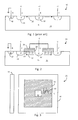
- Fig. 1 is a simplified cross-sectional view of a typical lateral PNP bipolar transistor 10.
- a central P-type emitter 12 is formed in an N-type base 14 (an epitaxial tub), grown on a silicon substrate.
- a P-type collector 16 Surrounding the emitter 12 is a P-type collector 16, formed as a ring, which may be generally rectangular or circular.
- a base contact region 18 makes electrical contact to the base 14.
- the emitter 12 is forward biased with respect to the base 14, and the collector 16 is reversed biased with respect to the base 14.
- Carriers from the emitter 12 (holes) entering the depletion region are swept into the collector 16 by the electric field, resulting in amplification (gain) of the base current.
- the transistor operates over a range of frequencies, and noise inherently occurs in the amplified signal due to the device physics. Generally, noise increases at very low frequencies.
- the crystalline structure of the silicon enables such transistor operation.
- One contributor of low frequency noise also known as 1/f noise, is due to surface defects as a result of the crystalline structure being discontinuous at the base's surface between the base-emitter interface and the base-collector interface. Such 1/f noise sets a limit on the minimum detectable signal at the low frequencies.
- the surface defects increase the recombination of the carriers in the base near the surface, where the electronic band structure changes. This is believed due to charge traps caused by the defects in the crystalline structure near the surface.
- the surface defect problem also occurs to a much smaller extent in some vertical bipolar transistors, since a portion of the emitter-base interface is near the surface of the silicon. In such transistors, some current flows laterally in the base near the surface. Such lateral flow that takes place near the surface is affected by the surface defects, resulting in 1/f noise.
- the 1/f corner is where the 1/f noise drops down to meet the white noise level.
- the invention repels the minority carriers in the base region (e.g., holes for an N-type base) near the base region surface to cause the lateral current flow to take place further below the surface between the emitter and collector regions to mitigate the effect of surface defects between the emitter and collector regions.
- the base region e.g., holes for an N-type base
- a thin gate oxide such as less than 600 Angstroms ( ⁇ ) is formed over the base surface region between the emitter and collector.
- the thin gate oxide should have minimal mobile charges and be of a very high quality, such as a thermally grown oxide.
- a conductive gate such as doped polysilicon, is then formed over the gate oxide and biased at the emitter voltage (or other voltage more positive than the base for a PNP transistor).
- the gate when the emitter is forward biased with respect to the base to turn the transistor on, the gate is at a positive potential relative to the base. This causes the holes in the base near the surface, conducting the emitter-collector current, to be repelled away from the surface and causes electrons in the base to be attracted to the base surface, so that the conduction (hole current) is carried out further from the surface.
- the conduction hole current
- This technique is applicable to lateral NPN transistors as well.
- the gate's electric field repels the base's minority carriers near the base surface to cause more lateral current to flow deeper into the silicon to mitigate the effect of the surface defects.
- gate oxide By making a high quality gate oxide, there will be minimal mobile charges in the oxide that would affect the repulsion of the minority carriers in the base, and the gate oxide may be formed very thin to generate a high electric field, yet have a sufficiently high breakdown voltage.
- a plasma-grown gate oxide is generally not desirable since such an oxide typically includes mobile charges as a result of the plasma process.
- the invention reduces the surface effect contributing to 1/f noise in a lateral or vertical bipolar transistor.
- the invention is applicable to PNP and NPN transistors.
- a lateral PNP transistor is used in the example.
- the invention is applicable to a vertical bipolar transistor to the extent that the vertical transistor operation involves some lateral current flow near the base surface.
- conventional vertical transistors typically have lower 1/f noise than conventional lateral transistors.
- the resulting 1/f noise of the lateral transistor was lower than the 1/f noise of a high quality vertical transistor and lower than any bipolar transistor known to the inventor. Therefore, the 1/f corner was reduced.
- Fig. 2 is a cross-sectional view of a lateral PNP bipolar transistor 22 in accordance with one embodiment of the invention.
- the emitter 12, base 14, collector 16, and base contact region 18 may be identical to the prior art Fig. 1 transistor.
- the base 14 is preferably epitaxially grown, rather than being implanted.
- a high quality, thin gate oxide 26 is thermally grown, using conventional techniques, over the base 14 substantially between the emitter 12 and collector 16.
- the gate oxide 26 may have a thickness less than 1000 ⁇ , and preferably less than 600 ⁇ . In one embodiment, the gate oxide 26 is between 200-300 ⁇ .
- a high quality, thermally grown gate oxide 26 of a given thickness can also withstand a greater voltage than a plasma-grown oxide, enabling the gate oxide 26 to be made slightly thinner (e.g., less than 300 ⁇ ) while not breaking down using standard operating voltages, such as 5 volts.
- a thinner oxide 26 enables the creation of a higher electrical field in the underlying silicon with a given voltage across the base/gate.
- a conductive gate 28 is then formed over the gate oxide 26.
- the gate 28 may be a highly doped polysilicon or a metal.
- the gate 28 is electrically tied to the emitter 12, such as with a metal trace, so as to have a positive potential relative to the underlying base 14 when the emitter-base junction is forward biased to turn on the transistor 22. Tying the gate 28 to the emitter typically ensures that the parasitic PMOS device formed by the gate 28 stays off.
- the gate 28 may be coupled to any suitable voltage more positive than the base 14, for a PNP transistor. The gate voltage should be constant when the transistor is conducting to avoid any modulation.
- the positive potential on the gate 28 When the transistor 22 is on, the positive potential on the gate 28 generates an electric field that repels the holes in the base (i.e., the minority current in the base) away from the surface and causes electrons 30 near the base 14 surface to accumulate at the surface. This forces the hole current 32 (between the emitter 12 and collector 16) to occur below the surface of the base 14 and away from the surface traps. Therefore, the 1/f noise is reduced and the 1/f corner occurs at a lower frequency.
- Dielectric layers other than an oxide may be formed instead of the oxide 26.
- the gate 28 may ultimately extend over the base-emitter and base-collector interfaces somewhat, which is preferred.
- This technique of reducing the effect of surface defects in a lateral bipolar transistor is equally applicable to a lateral NPN transistor, where all the polarities in the transistor 22 are reversed.
- the gate 28 is then negatively biased with respect to the P-type base when the transistor is on, causing holes in the P-type base to accumulate at the surface and electrons (i.e., the minority current in the base) to be repelled by the gate 28.
- Fig. 3 is a top down view of the transistor 22 of Fig. 2 .
- the regions are shown rectangular but would often have rounded corners or may be circular.
- the insulated gate 28 over the base 14 is shown to create a parasitic PMOS device 30 with a Vgs of 0 volts (if the gate 28 is tied to the emitter 12).
- a thick second oxide layer (e.g., about 0.6 micron or greater) is formed over the gate 28, where the second oxide layer has openings over the emitter 12 and the gate 28 conductor material.
- An emitter metal is then deposited over the second oxide layer to form the emitter conductor and short the gate 28 to the emitter 12. Other means may be used to short the gate 28 to the emitter 12.
- the gate 28 is shown formed over substantially the entire base 14 between the emitter 12 and collector 16 to maximize the effectiveness of the invention, the gate 28 can be smaller to reduce the effect of the surface defects over a smaller portion of the base.
- the base 14 may be a doped region formed by masking and doping a region of a silicon surface. The emitter and collector are then formed in the doped base region or otherwise in contact with the doped base region.
- the invention is particularly applicable to precision devices used for DC measurement as well as to circuits that up-convert 1/f noise, such as phase locked loop circuits.
- the invention has also been shown to cause reductions in offset shifts during burn in and to reduce long term drift (e.g., change in Vbe over time). These were unexpected and significant benefits. This allows amplifier and reference circuits incorporating the lateral bipolar transistors to be more stable over the lifetime of the product so as to be more valuable for precision DC measurements.
- a thick oxide e.g., greater than I micron
- metal shield layer over the thick oxide in electrical contact with the emitter.
- Such thick oxide is usually plasma-grown (typically lower quality oxide) rather than thermally grown to quickly develop the required thickness.
- the thick oxide may also be used for planarization.
- the metal shield layer over the thick oxide has a blocking function by reducing the effects of fields generated above the transistor such as the fields created by overlying conductors or the field created by electrical charges within the plastic package.
- Such metal even if biased with the emitter voltage, would only form a very weak coupling to the base due to the oxide thickness and would not have a significant effect on lowering the 1/f corner.
- the present invention controls the surface charges by coupling a relatively large electrical field to the base near the surface due to the thinness of the gate oxide.
- the prior art metal shield layer separated from the transistor surface by a thick oxide (typically plasma-grown), was biased with a higher potential than the emitter potential (for a PNP transistor) in an attempt to mitigate the effect of surface defects, the required potential would be too high to be practical. Accordingly, there is no suggestion to use the prior art shield layer to reduce the effect of surface defects.
Landscapes
- Bipolar Transistors (AREA)
- Insulated Gate Type Field-Effect Transistor (AREA)
Abstract
Description
- This invention relates to bipolar transistors and, in particular, to a technique for reducing low frequency noise in such transistors.
- In a lateral bipolar transistor, the majority of the current flows near the surface of the silicon rather than vertically down into the silicon, in contrast to a vertical transistor.
-
Fig. 1 is a simplified cross-sectional view of a typical lateral PNPbipolar transistor 10. A central P-type emitter 12 is formed in an N-type base 14 (an epitaxial tub), grown on a silicon substrate. Surrounding theemitter 12 is a P-type collector 16, formed as a ring, which may be generally rectangular or circular. Abase contact region 18 makes electrical contact to thebase 14. To turn thetransistor 10 on, theemitter 12 is forward biased with respect to thebase 14, and thecollector 16 is reversed biased with respect to thebase 14. Carriers from the emitter 12 (holes) entering the depletion region are swept into thecollector 16 by the electric field, resulting in amplification (gain) of the base current. The transistor operates over a range of frequencies, and noise inherently occurs in the amplified signal due to the device physics. Generally, noise increases at very low frequencies. - The crystalline structure of the silicon enables such transistor operation. One contributor of low frequency noise, also known as 1/f noise, is due to surface defects as a result of the crystalline structure being discontinuous at the base's surface between the base-emitter interface and the base-collector interface. Such 1/f noise sets a limit on the minimum detectable signal at the low frequencies.
- The surface defects increase the recombination of the carriers in the base near the surface, where the electronic band structure changes. This is believed due to charge traps caused by the defects in the crystalline structure near the surface.
- In the example of
Fig. 1 , due to the surface defects, the percentage of holes from theemitter 12 entering thebase 14 that recombine with electrons in thebase 14 is increased near the surface of thebase 14. In a lateral bipolar transistor, most of the emitter-collector current 20 flows near the surface since the emitter and collector doped regions are relatively shallow. Therefore, the effect of the surface defects is significant. The reason why the noise is 1/f related is extensively discussed in various published papers and is well known. - The surface defect problem also occurs to a much smaller extent in some vertical bipolar transistors, since a portion of the emitter-base interface is near the surface of the silicon. In such transistors, some current flows laterally in the base near the surface. Such lateral flow that takes place near the surface is affected by the surface defects, resulting in 1/f noise.
- It is desirable for various applications, such as test equipment, data acquisition, and A/D converters, to lower the 1/f noise corner. The 1/f corner is where the 1/f noise drops down to meet the white noise level.
- The invention repels the minority carriers in the base region (e.g., holes for an N-type base) near the base region surface to cause the lateral current flow to take place further below the surface between the emitter and collector regions to mitigate the effect of surface defects between the emitter and collector regions.
- A thin gate oxide, such as less than 600 Angstroms (Å), is formed over the base surface region between the emitter and collector. The thin gate oxide should have minimal mobile charges and be of a very high quality, such as a thermally grown oxide. A conductive gate, such as doped polysilicon, is then formed over the gate oxide and biased at the emitter voltage (or other voltage more positive than the base for a PNP transistor).
- In the example of a PNP transistor, when the emitter is forward biased with respect to the base to turn the transistor on, the gate is at a positive potential relative to the base. This causes the holes in the base near the surface, conducting the emitter-collector current, to be repelled away from the surface and causes electrons in the base to be attracted to the base surface, so that the conduction (hole current) is carried out further from the surface. Thus, there is less recombination at the surface due to the surface defects, and 1/f noise is reduced. Thus, the 1/f corner is lowered.
- This technique is applicable to lateral NPN transistors as well. In either a PNP or NPN transistor, the gate's electric field repels the base's minority carriers near the base surface to cause more lateral current to flow deeper into the silicon to mitigate the effect of the surface defects.
- By making a high quality gate oxide, there will be minimal mobile charges in the oxide that would affect the repulsion of the minority carriers in the base, and the gate oxide may be formed very thin to generate a high electric field, yet have a sufficiently high breakdown voltage. A plasma-grown gate oxide is generally not desirable since such an oxide typically includes mobile charges as a result of the plasma process.
- There is no lower limit to the thinness of the gate oxide, except for its ability to withstand the voltage across the gate oxide without breaking down.
- Other embodiments are described.
-
-
Fig. 1 is a cross-sectional view of a prior art lateral PNP bipolar transistor. -
Fig. 2 is a cross-sectional view of a lateral PNP bipolar transistor in accordance with one embodiment of the invention. -
Fig. 3 is a top down view of the transistor ofFig. 2 . - Elements that are the same or equivalent are labeled with the same numeral.
- The invention reduces the surface effect contributing to 1/f noise in a lateral or vertical bipolar transistor. The invention is applicable to PNP and NPN transistors. A lateral PNP transistor is used in the example. The invention is applicable to a vertical bipolar transistor to the extent that the vertical transistor operation involves some lateral current flow near the base surface.
- Historically, conventional vertical transistors typically have lower 1/f noise than conventional lateral transistors. In a test of a lateral transistor implementing the present invention, the resulting 1/f noise of the lateral transistor was lower than the 1/f noise of a high quality vertical transistor and lower than any bipolar transistor known to the inventor. Therefore, the 1/f corner was reduced.
-
Fig. 2 is a cross-sectional view of a lateral PNPbipolar transistor 22 in accordance with one embodiment of the invention. Theemitter 12,base 14,collector 16, andbase contact region 18 may be identical to the prior artFig. 1 transistor. Thebase 14 is preferably epitaxially grown, rather than being implanted. - A high quality,
thin gate oxide 26 is thermally grown, using conventional techniques, over thebase 14 substantially between theemitter 12 andcollector 16. Thegate oxide 26 may have a thickness less than 1000Å, and preferably less than 600Å. In one embodiment, thegate oxide 26 is between 200-300Å. By thermally growing thegate oxide 26, rather than growing it using a plasma process, there are minimal mobile charges in theoxide 26. A high quality, thermally growngate oxide 26 of a given thickness can also withstand a greater voltage than a plasma-grown oxide, enabling thegate oxide 26 to be made slightly thinner (e.g., less than 300Å) while not breaking down using standard operating voltages, such as 5 volts. Athinner oxide 26 enables the creation of a higher electrical field in the underlying silicon with a given voltage across the base/gate. - A
conductive gate 28 is then formed over thegate oxide 26. Thegate 28 may be a highly doped polysilicon or a metal. Thegate 28 is electrically tied to theemitter 12, such as with a metal trace, so as to have a positive potential relative to theunderlying base 14 when the emitter-base junction is forward biased to turn on thetransistor 22. Tying thegate 28 to the emitter typically ensures that the parasitic PMOS device formed by thegate 28 stays off. Alternatively, thegate 28 may be coupled to any suitable voltage more positive than the base 14, for a PNP transistor. The gate voltage should be constant when the transistor is conducting to avoid any modulation. - When the
transistor 22 is on, the positive potential on thegate 28 generates an electric field that repels the holes in the base (i.e., the minority current in the base) away from the surface and causeselectrons 30 near the base 14 surface to accumulate at the surface. This forces the hole current 32 (between theemitter 12 and collector 16) to occur below the surface of thebase 14 and away from the surface traps. Therefore, the 1/f noise is reduced and the 1/f corner occurs at a lower frequency. - Dielectric layers other than an oxide may be formed instead of the
oxide 26. - In an actual embodiment, due to diffusion of dopants in the emitter and collector during processing of the silicon wafer, the
gate 28 may ultimately extend over the base-emitter and base-collector interfaces somewhat, which is preferred. - This technique of reducing the effect of surface defects in a lateral bipolar transistor is equally applicable to a lateral NPN transistor, where all the polarities in the
transistor 22 are reversed. Thegate 28 is then negatively biased with respect to the P-type base when the transistor is on, causing holes in the P-type base to accumulate at the surface and electrons (i.e., the minority current in the base) to be repelled by thegate 28. This forces the electron current between the N-type emitter and N-type collector below the surface of the base and away from the surface traps. Therefore, the 1/f noise is reduced and the 1/f corner occurs at a lower frequency. -
Fig. 3 is a top down view of thetransistor 22 ofFig. 2 . The regions are shown rectangular but would often have rounded corners or may be circular. Theinsulated gate 28 over thebase 14 is shown to create aparasitic PMOS device 30 with a Vgs of 0 volts (if thegate 28 is tied to the emitter 12). - In one embodiment, a thick second oxide layer (e.g., about 0.6 micron or greater) is formed over the
gate 28, where the second oxide layer has openings over theemitter 12 and thegate 28 conductor material. An emitter metal is then deposited over the second oxide layer to form the emitter conductor and short thegate 28 to theemitter 12. Other means may be used to short thegate 28 to theemitter 12. - Although the
gate 28 is shown formed over substantially theentire base 14 between theemitter 12 andcollector 16 to maximize the effectiveness of the invention, thegate 28 can be smaller to reduce the effect of the surface defects over a smaller portion of the base. - Instead of the base 14 being epitaxially grown over a silicon substrate, the base may be a doped region formed by masking and doping a region of a silicon surface. The emitter and collector are then formed in the doped base region or otherwise in contact with the doped base region.
- The invention is particularly applicable to precision devices used for DC measurement as well as to circuits that up-convert 1/f noise, such as phase locked loop circuits. The invention has also been shown to cause reductions in offset shifts during burn in and to reduce long term drift (e.g., change in Vbe over time). These were unexpected and significant benefits. This allows amplifier and reference circuits incorporating the lateral bipolar transistors to be more stable over the lifetime of the product so as to be more valuable for precision DC measurements.
- It is known to form a thick oxide (e.g., greater than I micron) over the entire surface of a lateral transistor, followed by forming a metal shield layer over the thick oxide in electrical contact with the emitter. Such thick oxide is usually plasma-grown (typically lower quality oxide) rather than thermally grown to quickly develop the required thickness. The thick oxide may also be used for planarization. The metal shield layer over the thick oxide has a blocking function by reducing the effects of fields generated above the transistor such as the fields created by overlying conductors or the field created by electrical charges within the plastic package. Such metal, even if biased with the emitter voltage, would only form a very weak coupling to the base due to the oxide thickness and would not have a significant effect on lowering the 1/f corner. In contrast to such prior art thick oxides and the "blocking" shields, the present invention controls the surface charges by coupling a relatively large electrical field to the base near the surface due to the thinness of the gate oxide.
- If the prior art metal shield layer, separated from the transistor surface by a thick oxide (typically plasma-grown), was biased with a higher potential than the emitter potential (for a PNP transistor) in an attempt to mitigate the effect of surface defects, the required potential would be too high to be practical. Accordingly, there is no suggestion to use the prior art shield layer to reduce the effect of surface defects.
- While particular embodiments of the present invention have been shown and described, it will be obvious to those skilled in the art that changes and modifications may be made without departing from this invention in its broader aspects. The appended claims are to encompass within their scope all such changes and modifications as fall within the true spirit and scope of this invention.
Claims (15)
- A bipolar transistor comprising:an emitter of a first conductivity type;a collector of the first conductivity type;a base of a second conductivity type between the emitter and the collector, the base having a surface portion, the emitter, base, and collector forming a bipolar transistor;a gate dielectric formed over at least a portion of the surface portion of the base between the emitter and collector; anda conductive gate formed over the gate dielectric, the gate being coupled to a voltage potential, the gate dielectric and voltage potential being such that, when the transistor is turned on by forward biasing the emitter relative to the base, a resulting electric field generated by the gate forces more minority current in the base to be conducted deeper beneath the surface portion of the base between the emitter and collector.
- The transistor of Claim 1 wherein the transistor is a lateral transistor.
- The transistor of Claims 1 or 2 wherein the gate dielectric is less than 1000 Angstroms thick; or
wherein the gate dielectric is less than 600 Angstroms thick; or
wherein the gate dielectric is less than 300 Angstroms thick. - The transistor of any of the preceding claims wherein the gate dielectric is thermally grown.
- The transistor of any of the preceding claims wherein the gate is coupled to the emitter so as to have the same potential as the emitter.
- The transistor of any of the preceding claims wherein the transistor is a PNP type, and the gate is connected to a voltage more positive than the base; or
wherein the transistor is an NPN type, and the gate is connected to a voltage more negative than the base. - The transistor of any of the preceding claims wherein the resulting electric field generated by the gate reduces 1/f noise in the transistor; and/or
wherein the resulting electric field generated by the gate lowers a 1/f noise corner of the transistor. - The transistor of any of the preceding claims wherein the base is epitaxially grown.
- A method of operating a bipolar transistor, the transistor comprising an emitter of a first conductivity type, a collector of the first conductivity type, and a base of a second conductivity type between the emitter and the collector, the base having a surface portion between the emitter and the collector, the method comprising:turning on the transistor by forward biasing the emitter relative to the base; andapplying a voltage to a conductive gate, insulated from the surface portion by a gate dielectric, such that minority carriers in the base are repelled from the surface portion by an electric field created between the base and the gate to force more minority current in the base to be conducted deeper beneath the surface portion of the base between the emitter and collector.
- The method of Claim 9 wherein the gate dielectric does not extend completely over the emitter and collector.
- The method of Claims 9 or 10 wherein the transistor is a lateral transistor; and/or
wherein the gate dielectric is less than 1000 Angstroms thick; and/or
wherein the gate dielectric is less than 600 Angstroms thick. - The method of any one of claims 9 to 11 further comprising thermally growing the gate dielectric.
- The method of any one of claims 9 to 12 wherein the step of applying the voltage to the gate comprises coupling the gate to the emitter so as to have the same potential as the emitter.
- The method of any one of claims 9 to 13 wherein the transistor is a PNP type, and the gate is connected to a voltage more positive than the base; or
wherein the transistor is an NPN type, and the gate is connected to a voltage more negative than the base. - The method of any one of claims 9 to 14 wherein the resulting electric field generated by the gate reduces 1/f noise in the transistor; and/or
wherein the resulting electric field generated by the gate lowers a 1/f noise corner of the transistor.
Applications Claiming Priority (1)
| Application Number | Priority Date | Filing Date | Title |
|---|---|---|---|
| US13/829,598 US20140266393A1 (en) | 2013-03-14 | 2013-03-14 | Bipolar transistor with lowered 1/f noise |
Publications (1)
| Publication Number | Publication Date |
|---|---|
| EP2779241A1 true EP2779241A1 (en) | 2014-09-17 |
Family
ID=50280116
Family Applications (1)
| Application Number | Title | Priority Date | Filing Date |
|---|---|---|---|
| EP14000884.8A Withdrawn EP2779241A1 (en) | 2013-03-14 | 2014-03-12 | Bipolar transistor with lowered 1/F noise |
Country Status (4)
| Country | Link |
|---|---|
| US (1) | US20140266393A1 (en) |
| EP (1) | EP2779241A1 (en) |
| CN (1) | CN104051508A (en) |
| TW (1) | TW201436201A (en) |
Families Citing this family (3)
| Publication number | Priority date | Publication date | Assignee | Title |
|---|---|---|---|---|
| CN108447901B (en) * | 2018-02-28 | 2021-03-23 | 西安微电子技术研究所 | An anti-total dose radiation PNP transistor structure |
| CN114093937B (en) * | 2021-11-25 | 2023-08-22 | 中国电子科技集团公司第二十四研究所 | Bipolar transistor and preparation method thereof |
| CN114843340A (en) * | 2022-04-20 | 2022-08-02 | 华虹半导体(无锡)有限公司 | Lateral bipolar semiconductor device |
Citations (3)
| Publication number | Priority date | Publication date | Assignee | Title |
|---|---|---|---|---|
| JPH09213708A (en) * | 1996-01-30 | 1997-08-15 | Nec Yamagata Ltd | Lateral bipolar transistor and manufacturing method thereof |
| JPH10270458A (en) * | 1997-03-27 | 1998-10-09 | New Japan Radio Co Ltd | Lateral bipolar transistor |
| US20040256678A1 (en) * | 2003-04-07 | 2004-12-23 | Sanyo Electric Co., Ltd. | Semiconductor device |
Family Cites Families (4)
| Publication number | Priority date | Publication date | Assignee | Title |
|---|---|---|---|---|
| NL8100347A (en) * | 1981-01-26 | 1982-08-16 | Philips Nv | SEMICONDUCTOR DEVICE WITH A PROTECTION DEVICE. |
| CA2115477A1 (en) * | 1994-02-11 | 1995-08-12 | Jonathan H. Orchard-Webb | Esd input protection arrangement |
| US5670396A (en) * | 1995-11-21 | 1997-09-23 | Lucent Technologies Inc. | Method of forming a DMOS-controlled lateral bipolar transistor |
| US8609501B2 (en) * | 2011-09-09 | 2013-12-17 | Texas Instruments Incorporated | Fluorine implant under isolation dielectric structures to improve bipolar transistor performance and matching |
-
2013
- 2013-03-14 US US13/829,598 patent/US20140266393A1/en not_active Abandoned
-
2014
- 2014-01-21 TW TW103102148A patent/TW201436201A/en unknown
- 2014-02-21 CN CN201410059004.7A patent/CN104051508A/en active Pending
- 2014-03-12 EP EP14000884.8A patent/EP2779241A1/en not_active Withdrawn
Patent Citations (3)
| Publication number | Priority date | Publication date | Assignee | Title |
|---|---|---|---|---|
| JPH09213708A (en) * | 1996-01-30 | 1997-08-15 | Nec Yamagata Ltd | Lateral bipolar transistor and manufacturing method thereof |
| JPH10270458A (en) * | 1997-03-27 | 1998-10-09 | New Japan Radio Co Ltd | Lateral bipolar transistor |
| US20040256678A1 (en) * | 2003-04-07 | 2004-12-23 | Sanyo Electric Co., Ltd. | Semiconductor device |
Also Published As
| Publication number | Publication date |
|---|---|
| TW201436201A (en) | 2014-09-16 |
| CN104051508A (en) | 2014-09-17 |
| US20140266393A1 (en) | 2014-09-18 |
Similar Documents
| Publication | Publication Date | Title |
|---|---|---|
| JP6066933B2 (en) | Electrode structure of semiconductor devices | |
| US8378390B2 (en) | Silicon carbide bipolar junction transistor (BJT) having a surface electrode disposed on top of a dielectric layer formed at a region between emitter contact and base contact | |
| US8975640B2 (en) | Heterojunction semiconductor device and manufacturing method | |
| US20120329238A1 (en) | Method For Forming A Transient Voltage Suppressor Having Symmetrical Breakdown Voltages | |
| US8736013B2 (en) | Schottky diode with opposite-polarity schottky diode field guard ring | |
| JP2003282892A (en) | Method and structure of low capacitance ESD resistant diode | |
| US8907351B2 (en) | Bipolar junction transistor in silicon carbide with improved breakdown voltage | |
| US9905558B1 (en) | Conductivity modulated drain extended MOSFET | |
| JPS62131580A (en) | High speed switching lateral insulated gate transistor | |
| EP2779241A1 (en) | Bipolar transistor with lowered 1/F noise | |
| US11469315B2 (en) | Bipolar junction transistor with biased structure between base and emitter regions | |
| US4942440A (en) | High voltage semiconductor devices with reduced on-resistance | |
| US4868921A (en) | High voltage integrated circuit devices electrically isolated from an integrated circuit substrate | |
| US20060071292A1 (en) | Reduced guard ring in schottky barrier diode structure | |
| Khai et al. | High-frequency characteristics of InGaP/GaAs double heterojunction bipolar transistor epitaxially grown on 200 mm Ge/Si wafers | |
| US7352051B2 (en) | Cascode, cascode circuit and method for vertical integration of two bipolar transistors into a cascode arrangement | |
| US8357985B2 (en) | Bipolar transistor with guard region | |
| CN119069522B (en) | transistors and electronic devices | |
| CA2361752C (en) | A lateral field effect transistor of sic, a method for production thereof and a use of such a transistor | |
| US20140266407A1 (en) | Bipolar junction transistor and operating and manufacturing method for the same | |
| CN119342848B (en) | Semiconductor structure and forming method thereof | |
| EP0108945A1 (en) | High voltage semiconductor devices with reduced on-resistance | |
| US9935628B2 (en) | FET—bipolar transistor combination, and a switch comprising such a FET—bipolar transistor combination | |
| CN118213411A (en) | Semiconductor device and method for manufacturing the same |
Legal Events
| Date | Code | Title | Description |
|---|---|---|---|
| PUAI | Public reference made under article 153(3) epc to a published international application that has entered the european phase |
Free format text: ORIGINAL CODE: 0009012 |
|
| 17P | Request for examination filed |
Effective date: 20140312 |
|
| AK | Designated contracting states |
Kind code of ref document: A1 Designated state(s): AL AT BE BG CH CY CZ DE DK EE ES FI FR GB GR HR HU IE IS IT LI LT LU LV MC MK MT NL NO PL PT RO RS SE SI SK SM TR |
|
| AX | Request for extension of the european patent |
Extension state: BA ME |
|
| R17P | Request for examination filed (corrected) |
Effective date: 20150122 |
|
| RBV | Designated contracting states (corrected) |
Designated state(s): AL AT BE BG CH CY CZ DE DK EE ES FI FR GB GR HR HU IE IS IT LI LT LU LV MC MK MT NL NO PL PT RO RS SE SI SK SM TR |
|
| 17Q | First examination report despatched |
Effective date: 20161010 |
|
| STAA | Information on the status of an ep patent application or granted ep patent |
Free format text: STATUS: THE APPLICATION IS DEEMED TO BE WITHDRAWN |
|
| 18D | Application deemed to be withdrawn |
Effective date: 20170221 |