EP2779192B1 - Elektrisches/elektronisches Installationsgerät - Google Patents
Elektrisches/elektronisches Installationsgerät Download PDFInfo
- Publication number
- EP2779192B1 EP2779192B1 EP14150582.6A EP14150582A EP2779192B1 EP 2779192 B1 EP2779192 B1 EP 2779192B1 EP 14150582 A EP14150582 A EP 14150582A EP 2779192 B1 EP2779192 B1 EP 2779192B1
- Authority
- EP
- European Patent Office
- Prior art keywords
- light
- electric
- light conductor
- electronic installation
- installation device
- Prior art date
- Legal status (The legal status is an assumption and is not a legal conclusion. Google has not performed a legal analysis and makes no representation as to the accuracy of the status listed.)
- Active
Links
Images


Classifications
-
- H—ELECTRICITY
- H01—ELECTRIC ELEMENTS
- H01H—ELECTRIC SWITCHES; RELAYS; SELECTORS; EMERGENCY PROTECTIVE DEVICES
- H01H9/00—Details of switching devices, not covered by groups H01H1/00 - H01H7/00
- H01H9/18—Distinguishing marks on switches, e.g. for indicating switch location in the dark; Adaptation of switches to receive distinguishing marks
- H01H9/182—Illumination of the symbols or distinguishing marks
-
- H—ELECTRICITY
- H01—ELECTRIC ELEMENTS
- H01H—ELECTRIC SWITCHES; RELAYS; SELECTORS; EMERGENCY PROTECTIVE DEVICES
- H01H9/00—Details of switching devices, not covered by groups H01H1/00 - H01H7/00
- H01H9/02—Bases, casings, or covers
- H01H9/0271—Bases, casings, or covers structurally combining a switch and an electronic component
-
- H—ELECTRICITY
- H01—ELECTRIC ELEMENTS
- H01H—ELECTRIC SWITCHES; RELAYS; SELECTORS; EMERGENCY PROTECTIVE DEVICES
- H01H2219/00—Legends
- H01H2219/002—Legends replaceable; adaptable
- H01H2219/014—LED
-
- H—ELECTRICITY
- H01—ELECTRIC ELEMENTS
- H01H—ELECTRIC SWITCHES; RELAYS; SELECTORS; EMERGENCY PROTECTIVE DEVICES
- H01H2219/00—Legends
- H01H2219/036—Light emitting elements
-
- H—ELECTRICITY
- H01—ELECTRIC ELEMENTS
- H01H—ELECTRIC SWITCHES; RELAYS; SELECTORS; EMERGENCY PROTECTIVE DEVICES
- H01H2219/00—Legends
- H01H2219/036—Light emitting elements
- H01H2219/044—Edge lighting of layer
-
- H—ELECTRICITY
- H01—ELECTRIC ELEMENTS
- H01H—ELECTRIC SWITCHES; RELAYS; SELECTORS; EMERGENCY PROTECTIVE DEVICES
- H01H2219/00—Legends
- H01H2219/054—Optical elements
- H01H2219/062—Light conductor
-
- H—ELECTRICITY
- H01—ELECTRIC ELEMENTS
- H01H—ELECTRIC SWITCHES; RELAYS; SELECTORS; EMERGENCY PROTECTIVE DEVICES
- H01H2219/00—Legends
- H01H2219/054—Optical elements
- H01H2219/064—Optical isolation of switch sites
-
- H—ELECTRICITY
- H01—ELECTRIC ELEMENTS
- H01H—ELECTRIC SWITCHES; RELAYS; SELECTORS; EMERGENCY PROTECTIVE DEVICES
- H01H2300/00—Orthogonal indexing scheme relating to electric switches, relays, selectors or emergency protective devices covered by H01H
- H01H2300/03—Application domotique, e.g. for house automation, bus connected switches, sensors, loads or intelligent wiring
-
- Y—GENERAL TAGGING OF NEW TECHNOLOGICAL DEVELOPMENTS; GENERAL TAGGING OF CROSS-SECTIONAL TECHNOLOGIES SPANNING OVER SEVERAL SECTIONS OF THE IPC; TECHNICAL SUBJECTS COVERED BY FORMER USPC CROSS-REFERENCE ART COLLECTIONS [XRACs] AND DIGESTS
- Y02—TECHNOLOGIES OR APPLICATIONS FOR MITIGATION OR ADAPTATION AGAINST CLIMATE CHANGE
- Y02B—CLIMATE CHANGE MITIGATION TECHNOLOGIES RELATED TO BUILDINGS, e.g. HOUSING, HOUSE APPLIANCES OR RELATED END-USER APPLICATIONS
- Y02B90/00—Enabling technologies or technologies with a potential or indirect contribution to GHG emissions mitigation
- Y02B90/20—Smart grids as enabling technology in buildings sector
-
- Y—GENERAL TAGGING OF NEW TECHNOLOGICAL DEVELOPMENTS; GENERAL TAGGING OF CROSS-SECTIONAL TECHNOLOGIES SPANNING OVER SEVERAL SECTIONS OF THE IPC; TECHNICAL SUBJECTS COVERED BY FORMER USPC CROSS-REFERENCE ART COLLECTIONS [XRACs] AND DIGESTS
- Y04—INFORMATION OR COMMUNICATION TECHNOLOGIES HAVING AN IMPACT ON OTHER TECHNOLOGY AREAS
- Y04S—SYSTEMS INTEGRATING TECHNOLOGIES RELATED TO POWER NETWORK OPERATION, COMMUNICATION OR INFORMATION TECHNOLOGIES FOR IMPROVING THE ELECTRICAL POWER GENERATION, TRANSMISSION, DISTRIBUTION, MANAGEMENT OR USAGE, i.e. SMART GRIDS
- Y04S20/00—Management or operation of end-user stationary applications or the last stages of power distribution; Controlling, monitoring or operating thereof
- Y04S20/14—Protecting elements, switches, relays or circuit breakers
Definitions
- the present invention is based on a designed according to the preamble of the main claim electrical / electronic installation device.
- Such electrical / electronic installation devices are usually intended to affect a variety of installed in buildings actuators (Venetian blinds, lighting, sensors, security, etc.) as needed.
- a variety of installation devices such as switches, buttons, dimmers, etc. have become known, which can also be provided with lighting itself.
- first functional module is provided, which has a plurality of functional elements.
- a second functional module can be connected to the first functional module with the interposition of a cover frame.
- the second functional module is provided with an electrical circuit board, on the one hand has at least a plurality of provided for connection to the first functional module pins and on the other hand, is equipped with a plurality of LED modules.
- the electrical circuit board is associated with an existing, at least two differently shaped Lichtleit stresses intensities, and so forth.
- an electrical / electronic installation device for building system technology has become known in which a, projecting into an installation box function module is provided which has several functional elements.
- the functional module may be provided with an extension formed as an electrical circuit board, which is equipped with a plurality of switching elements and a plurality of light-conducting elements. To realize the switching elements is provided to arrange a Domschaltmatte on the circuit board.
- the present invention has for its object to provide an installation device, which allows a cost-effective manner with a particularly compact structure needs-based illumination over a, consisting of at least two differently shaped light guide fiber light guide assembly.
- the electrical / electronic installation device should in particular have a particularly homogeneously illuminated, centrally arranged, as well as flat executed first Lichtauskoppel Euro and at least one line-shaped second Lichtauskoppel Lake.
- two line-shaped second light coupling-out areas are to be provided, which receive the areally executed first light coupling-out area between them.
- both a backlight or search / ambient lighting and a functional lighting is realized by the light guide assembly in a particularly simple manner.
- both Lichtabschottungs freee to prevent stray light and light reflection effects for the realization of an optimized light utilization are realized in a particularly simple manner by the design of Domschaltmatte.
- such an electrical / electronic installation device for the building system technology mainly consists of a functional module 1, which protrudes with its base part 2 for installation in an installation box 3.
- the functional module 1 has a plurality of functional elements and is attached with the interposition of a cover frame 4 and a support ring 5, as usual in such installations in or on the installation box 3.
- the functional module 1 With the underside of his operating area, the functional module 1, as usual, for example, to lie on the wall in which the installation box 3 is located.
- the functional module 1 is provided with an electrical circuit board 6, which faces the back of the installation box 3, a plurality of pins provided for connection with connection elements and which is also rear side with several, necessary for function, electrical / electronic components (functional elements) equipped , For the sake of simplicity, neither the contact pins, nor the electrical / electronic components are shown.
- the electrical circuit board 6 On the back comes the electrical circuit board 6 to lie on a collar-shaped projection 7 of the base part 2.
- the electrical circuit board 6 on the front side that is to say facing the user, is assigned an optical waveguide arrangement consisting of a plurality of differently configured light-guiding bodies 8, 9 into which the light emitted by associated LED modules 13 is coupled.
- the electrical circuit board 6 is equipped on its front with twelve LED modules 13.
- the first light guide 8 of the light guide assembly is plate-shaped and integrally formed on two opposite edge regions, each with two, substantially provided triangular shaped Lichteinkoppel Schemeen 10.
- Each of the four Lichteinkoppel Schemee 10 is assigned an LED module 13 each.
- the optical waveguide arrangement has two rod-shaped second light-guiding bodies 9, which each have four light-coupling projections 11 in the area of their underside assigned to the electrical circuit board 6.
- Each of the two rod-shaped second light guide 9 comes with its underside partially on two of the triangular shaped Lichteinkoppel Schemee 10 of the plate-shaped first Lichtleit stresses 8 to the plant.
- Each Lichteinkoppelansatz 11 of the two second Lichtleitoasa 9 is assigned a LED module 13 each.
- both the first light-guiding body 8 and the two second light-guiding bodies 9 have areas that have a high-gloss polishing quality, such that total reflection occurs on these surfaces of the light-guiding bodies 8, 9.
- a Domschaltmatte 12 is provided, which rests with its back on the electrical circuit board 6.
- the Domschaltmatte 12 is designed and arranged such that the first Lichtleit stresses 8 of the light guide assembly comes directly to the front of the Domschaltmatte 12 to the plant.
- the two formed on the first Lichtleit analyses 8 Lichteinkoppel Complexe 10 are designed about half as strong as the other areas of the Lichtleit stresses 8.
- the two rod-shaped second Lichtleitko 9 are each associated with an edge region of the Lichtleit stresses 8 and With their underside, in each case in regions, two light-coupling regions 10 of the first light-guiding body 8 come into contact.
- the light guide assembly thus consists of a first plate-shaped light guide 8 and two rod-shaped second Lichtleit stressesn 9.
- the two second light guide 9 are arranged so that the first Lichtleitmaschine 8 is arranged with its first Lichtauskoppel Scheme 14 between them.
- the first Lichtauskoppel Complex 14 of the first Lichtleit analysess 8 is flat and provided with a Lichtauskoppel General.
- the two second light guide 9 of the light guide assembly each have a line-shaped second Lichtauskoppel Scheme 15, which is also each provided with a Lichtauskoppel Design.
- Domschaltmatte 12 has two laterally arranged, each provided with four Domschaltriin 16 switching areas 17. Between the two switching regions 17, a reflection region 18 is arranged, the surface of which, in terms of the order of magnitude, substantially corresponds to the surface of the first light-guiding body 8 coming to rest.
- the dome switching mat 12 has 12 recesses 19 for the passage of twelve LED modules 13, wherein at least some of these recesses are associated with reflection zones in order to influence the light emitted by the LED modules as needed.
- a further recess 21 is provided for a further LED module 20, which is present in the reflection region 18 of the Domschaltmatte 12.
- the light guide 8 of the light guide has in association with a hole 22 for receiving this further LED module 20.
- the inner walls of this hole 22 are provided with Lichtabschottungsschn so that the light emitted from the other LED module 20 light is not irradiated into the first light guide 18.
- the twelve recesses 19 of the dome switching mat 12 are designed so that an undesired overshoot in the light output of the twelve LED modules 13 is prevented as far as possible.
- the reflection region 18 is also provided in order to take care of a particularly homogeneous illumination of the areally executed first light extraction region 14 of the first light guide 8.
- the twelve LED blocks 13 and also the other LED block 20 are designed as a three-color LED.
- a holding plate 23 As further particularly from FIG. 1 and FIG. 2 It can be seen on the electrical circuit board 6 facing away from front of the Domschaltmatte 12 a holding plate 23.
- the holding plate 23 is provided for clipping with the base part 2, and has on its side facing away from the Domschaltmatte 12 eight first fasteners 24 to eight designed as pushbuttons actuators 26 safe, but still palpable to store.
- 23 further fastening elements 25 are provided on the holding plate, which serve to secure attachment of a Jerusalem internden on the holding plate 23
- Design cover 27 to allow.
- the design cover 27 is designed to be translucent, so that a homogeneous illumination over the first light extraction region 14 of the first light guide 8 is ensured.
Description
- Die vorliegende Erfindung geht von einem gemäß Oberbegriff des Hauptanspruches konzipierten elektrischen/elektronischen Installationsgerätes aus.
- Derartige elektrische/elektronische Installationsgeräte sind in der Regel dafür vorgesehen, eine Vielzahl von, in Gebäuden installierte Aktoren (Jalousieantriebe, Beleuchtungseinrichtungen, Fühler, Wächter usw.) bedarfsgerecht zu beeinflussen. Zu diesem Zweck sind die unterschiedlichsten Installationsgeräte, wie Schalter, Taster, Dimmer usw. bekannt geworden, die auch selber mit einer Beleuchtung versehen sein können.
- Durch die
DE 10 2004 043 649 B4 ist ein dem Oberbegriff des Hauptanspruch entsprechendes elektrisches/elektronisches Installationsgerät für die Gebäudesystemtechnik bekannt geworden. Bei diesem elektrischen/elektronischen Installationsgerät für die Gebäudesystemtechnik ist ein, in eine Installationsdose hineinragendes erstes Funktionsmodul vorgesehen, welches mehrere Funktionselemente aufweist. Ein zweites Funktionsmodul ist unter Zwischenschaltung eines Abdeckrahmens mit dem ersten Funktionsmodul verbindbar. Das zweite Funktionsmodul ist mit einer elektrischen Leiterplatte versehen, die einerseits zumindest mehrere zur Verbindung mit dem ersten Funktionsmodul vorgesehene Kontaktstifte aufweist und die andererseits mit mehreren LED-Bausteinen bestückt ist. Andererseits ist der elektrischen Leiterplatte eine, aus zumindest zwei verschiedenartig ausgebildeten Lichtleitkörpern bestehende Lichtleiteranordnung zugeordnet, in welche das von den LED-Bausteinen abgegebene Licht eingekoppelt wird. - Des Weiteren ist durch die
EP 2 043 123 A2 ein elektrisches/elektronisches Installationsgerät für die Gebäudesystemtechnik bekannt geworden, bei dem ein, in eine Installationsdose hineinragendes Funktionsmodul vorgesehen ist, welches mehrere Funktionselemente aufweist. Das Funktionsmodul kann mit einer als elektrische Leiterplatte ausgebildeten Verlängerung versehen sein, welche mit mehreren Schaltelementen und mehreren Lichtleitelementen bestückt ist. Zur Realisierung der Schaltelemente ist vorgesehen, auf der Leiterplatte eine Domschaltmatte anzuordnen. - Ausgehend von derart ausgebildeten elektrischen/elektronischen Installationsgeräten liegt der vorliegenden Erfindung die Aufgabe zugrunde, ein Installationsgerät zu schaffen, welches auf kostengünstige Art und Weise bei besonders kompaktem Aufbau eine bedarfsgerechte Ausleuchtung über eine, aus zumindest zwei verschiedenartig ausgebildeten Lichtleitkörpern bestehende Lichtleiteranordnung ermöglicht. Dabei soll das elektrische/elektronische Installationsgerät insbesondere einen besonders homogen ausgeleuchteten, zentral angeordneten, sowie flächig ausgeführten ersten Lichtauskoppelbereich und zumindest einen linienförmig ausgeführten zweiten Lichtauskoppelbereich aufweisen. Vorzugsweise sind zwei linienförmig ausgeführte zweite Lichtauskoppelbereiche vorzusehen, die den flächig ausgeführten ersten Lichtauskoppelbereich zwischen sich aufnehmen.
- Erfindungsgemäß wird diese Aufgabe durch die im Hauptanspruch angegebenen Merkmale gelöst.
- Bei einer solchen Ausbildung ist besonders vorteilhaft, dass durch die Lichtleiteranordnung auf besonders einfache Art und Weise sowohl eine Hintergrundbeleuchtung bzw. Such-/Ambientebeleuchtung als auch eine Funktionsbeleuchtung realisiert ist. Weiterhin ist besonders vorteilhaft, dass durch die Ausbildung der Domschaltmatte sowohl Lichtabschottungseffekte zur Verhinderung von Streulicht als auch Lichtreflektionseffekte zur Realisierung einer optimierten Lichtausnutzung auf besonders einfache Art und Weise verwirklicht sind.
- Weitere vorteilhafte Ausgestaltungen des erfindungsgemäßen Gegenstandes sind in den Unteransprüchen angegeben. Anhand eines Ausführungsbeispiels sei die Erfindung im Prinzip näher erläutert, dabei zeigt:
-
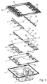
Fig. 1 : prinziphaft eine Explosionsdarstellung, wobei das Funktionsmodul in Zuordnung zur Installationsdose mit Abdeckrahmen und Tragring dargestellt ist; -
Fig. 2 : prinziphaft eine Explosionsdarstellung des Funktionsmoduls; -
Fig. 3 : prinziphaft die elektrische Leiterplatte, die Domschaltmatte und die Lichtleiteranordnung als Zusammenbau in räumlicher Darstellung. - Wie insbesondere aus
Figur 1 hervorgeht, besteht ein solches elektrisches/elektronisches Installationsgerät für die Gebäudesystemtechnik hauptsächlich aus einem Funktionsmodul 1, welches mit seinem Sockelteil 2 zur Installation in eine Installationsdose 3 hineinragt. Das Funktionsmodul 1 weist mehrere Funktionselemente auf und wird unter Zwischenschaltung eines Abdeckrahmens 4 und eines Tragringes 5, wie bei solchen Installationen üblich in, bzw. an der Installationsdose 3 befestigt. Mit der Unterseite seines Bedienbereiches kommt das Funktionsmodul 1, wie üblich, zum Beispiel auf der Wand zu liegen, in welcher sich die Installationsdose 3 befindet. - Wie insbesondere aus
Figur 2 undFigur 3 hervorgeht, ist das Funktionsmodul 1 mit einer elektrischen Leiterplatte 6 versehen, die rückseitig, also der Installationsdose 3 zugewandt, mehrere zur Verbindung mit Anschlusselementen vorgesehene Kontaktstifte aufweist und die zudem rückseitig mit mehreren, zur Funktion notwendigen, elektrischen/elektronischen Bauteilen (Funktionselemente) bestückt ist. Der Einfachheit halber sind weder die Kontaktstifte, noch die elektrischen/elektronischen Bauteile dargestellt. Rückseitig kommt die elektrische Leiterplatte 6 auf einem kragenförmigen Ansatz 7 des Sockelteils 2 zu liegen. Zudem ist der elektrischen Leiterplatte 6 vorderseitig, also dem Benutzer zugewandt, eine aus mehreren verschiedenartig ausgebildeten Lichtleitkörpern 8, 9 bestehende Lichtleiteranordnung zugeordnet, in welche das von zugeordneten LED-Bausteinen 13 abgegebene Licht eingekoppelt wird. Zu diesem Zweck ist die elektrische Leiterplatte 6 auf ihrer Vorderseite mit zwölf LED-Bausteinen 13 bestückt. Der erste Lichtleitkörper 8 der Lichtleiteranordnung ist plattenförmig ausgebildet und einstückig an zwei gegenüberliegenden Kantenbereichen mit jeweils zwei, im Wesentlichen dreieckförmig ausgebildeten Lichteinkoppelbereichen 10 versehen. Jedem der vier Lichteinkoppelbereiche 10 ist je ein LED-Baustein 13 zugeordnet. Außerdem weist die Lichtleiteranordnung zwei stabförmig ausgebildete zweite Lichtleitkörper 9 auf, die im Bereich ihrer der elektrischen Leiterplatte 6 zugeordneten Unterseite jeweils vier Lichteinkoppelansätze 11 aufweisen. Jeder der beiden stabförmig ausgebildeten zweiten Lichtleitkörper 9 kommt mit seiner Unterseite bereichsweise auf zwei der dreieckförmig ausgebildeten Lichteinkoppelbereiche 10 des plattenförmig ausgebildeten ersten Lichtleitkörpers 8 zur Anlage. Jedem Lichteinkoppelansatz 11 der beiden zweiten Lichtleitkörper 9 ist je ein LED-Baustein 13 zugeordnet. Um Lichtstreuung möglichst zu verhindern, weisen sowohl der erste Lichtleitkörper 8, als auch die beiden zweiten Lichtleitkörper 9 bereichsweise Oberflächen auf, die Hochglanzpoliergüte aufweisen, so dass an diesen Oberflächen der Lichtleitkörper 8, 9 Totalreflektion auftritt. Zur Realisierung von Schaltfunktionen ist eine Domschaltmatte 12 vorgesehen, die mit ihrer Rückseite auf der elektrischen Leiterplatte 6 aufliegt. Die Domschaltmatte 12 ist dabei derart ausgeführt und angeordnet, dass der erste Lichtleitkörper 8 der Lichtleiteranordnung direkt auf der Vorderseite der Domschaltmatte 12 zur Anlage kommt. Um einen besonders kompakten Aufbau zu gewährleisten, sind die beiden an den ersten Lichtleitkörper 8 angeformten Lichteinkoppelbereiche 10 etwa nur halb so stark ausgeführt, wie die übrigen Bereiche des Lichtleitkörpers 8. Die beiden stabförmig ausgebildeten zweiten Lichtleitkörper 9 sind je einem Kantenbereich des Lichtleitkörpers 8 zugeordnet und kommen mit ihrer Unterseite jeweils bereichsweise auf zwei Lichteinkoppelbereiche 10 des ersten Lichtleitkörpers 8 zur Anlage. Die Lichtleiteranordnung besteht also aus einem ersten plattenförmig ausgebildeten Lichtleitkörper 8 und zwei stabförmig ausgebildeten zweiten Lichtleitkörpern 9. Die beiden zweiten Lichtleitkörper 9 sind dabei so angeordnet, dass der erste Lichtleitkörper 8 mit seinem ersten Lichtauskoppelbereich 14 zwischen ihnen angeordnet ist. Der erste Lichtauskoppelbereich 14 des ersten Lichtleitkörpers 8 ist flächig ausgeführt und mit einer Lichtauskoppelstruktur versehen. Die beiden zweiten Lichtleitkörper 9 der Lichtleiteranordnung weisen jeweils einen linienförmig ausgebildeten zweiten Lichtauskoppelbereich 15 auf, der jeweils ebenfalls mit einer Lichtauskoppelstruktur versehen ist. - Die mit ihrer Rückseite auf der elektrischen Leiterplatte 6 zur Anlage kommende Domschaltmatte 12 weist zwei seitlich angeordnete, je mit vier Domschaltelementen 16 versehene Schaltbereiche 17 auf. Zwischen den beiden Schaltbereichen 17 ist ein Reflektionsbereich 18 angeordnet, dessen Fläche größenordnungsmäßig im Wesentlichen der zur Auflage kommenden Fläche des ersten Lichtleitkörpers 8 entspricht. Die Domschaltmatte 12 weist zum Durchtritt von zwölf LED-Bausteinen 13 zwölf Ausnehmungen 19 auf, wobei zumindest einen Teil dieser Ausnehmungen Reflektionszonen zugeordnet sind, um das von den LED-Bausteinen abgestrahlte Licht bedarfsgerecht zu beeinflussen. Außerdem ist für einen weiteren LED-Baustein 20 eine weitere Ausnehmung 21 vorgesehen, welche im Reflektionsbereich 18 der Domschaltmatte 12 vorhanden ist. Der Lichtleitkörper 8 der Lichtleitanordnung weist in Zuordnung zudem ein Loch 22 zur Aufnahme dieses weiteren LED-Bausteines 20 auf. Die Innenwandungen dieses Loches 22 sind mit Lichtabschottungsmitteln versehen, damit das von dem weiteren LED-Baustein 20 abgegebene Licht nicht in den ersten Lichtleitkörper 18 eingestrahlt wird. Um das von den zwölf LED-Bausteinen 13 abgegebene Licht des weiteren bedarfsgerecht zu beeinflussen, sind die zwölf Ausnehmungen 19 der Domschaltmatte 12 so ausgeführt, dass ein unerwünschtes Überstrahlen bei der Lichtabgabe der zwölf LED-Bausteinen 13 möglichst verhindert wird. Zur optimierten Lichtausnutzung der LED-Bausteine 13 weist die Domschaltmatte 12, wie bereits erwähnt, den Reflektionsbereich 18 und mehrere Reflektionszonen auf. Weiterhin ist der Reflektionsbereich 18 auch dafür vorgesehen, um für eine besonders homogene Ausleuchtung des flächig ausgeführten ersten Lichtauskoppelbereiches 14 des ersten Lichtleiters 8 Sorge zu tragen. Um farbiges Licht abgeben zu können, sind die zwölf LED-Bausteine 13 und auch der weitere LED-Baustein 20 als Dreifarben-LED ausgeführt.
- Wie des Weiteren insbesondere aus
Figur 1 undFigur 2 hervorgeht, liegt auf der der elektrischen Leiterplatte 6 abgewandten Vorderseite der Domschaltmatte 12 eine Halteplatte 23 auf. Die Halteplatte 23 ist zum Verclipsen mit dem Sockelteil 2 vorgesehen, und weist an ihrer, der Domschaltmatte 12 abgewandten Seite acht erste Befestigungselemente 24 auf, um acht als Drucktasten ausgeführte Betätigungselemente 26 sicher, aber dennoch tastbeweglich, zu lagern. Außerdem sind an der Halteplatte 23 weitere Befestigungselemente 25 vorgesehen, die dazu dienen, eine sichere Befestigung einer, auf die Halteplatte 23 aufzusetzenden Designabdeckung 27 zu ermöglichen. Die Designabdeckung 27 ist transluzent ausgeführt, damit eine homogene Ausleuchtung über den ersten Lichtauskoppelbereich 14 des ersten Lichtleiters 8 sichergestellt ist. Durch das Verclipsen der Halteplatte 23 mit dem Sockelteil 2 entsteht, mit Zuordnung der Lichtleiteranordnung, der Domschaltmatte 12 und der elektrischen Leiterplatte 6 auf einfache Art und Weise ein separat zu handhabendes Gerätemodul, welches zu seiner Komplettierung nur noch mit den Betätigungselemente 26 und der Designabdeckung 27 bestückt werden muss. -
- 1
- Funktionsmodul
- 2
- Sockelteil
- 3
- Installationsdose
- 4
- Abdeckrahmen
- 5
- Tragring
- 6
- Leiterplatte
- 7
- Kragenförmiger Ansatz
- 8
- Erster Lichtleitkörper
- 9
- Zweiter Lichtleitkörper
- 10
- Lichteinkoppelbereich
- 11
- Lichteinkoppelansatz
- 12
- Domschaltmatte
- 13
- LED-Bausteine
- 14
- Erster Lichtauskoppelbereich
- 15
- Zweiter Lichtauskoppelbereich
- 16
- Domschaltelement
- 17
- Schaltbereich
- 18
- Reflektionsbereich
- 19
- Ausnehmungen
- 20
- Weiterer LED-Baustein
- 21
- Weitere Ausnehmung
- 22
- Loch
- 23
- Halteplatte
- 24
- Erste Befestigungselemente
- 25
- Zweite Befestigungselemente
- 26
- Betätigungselement
- 27
- Designabdeckung
Claims (12)
- Elektrisches/elektronisches Installationsgerät für die Gebäudesystemtechnik mit einem mehrere Funktionselemente aufweisenden Funktionsmodul (1), welches unter Zwischenschaltung eines Abdeckrahmens (4) und eines Tragringes (5) zur Installation in eine Installationsdose (3) vorgesehen ist, wobei das Funktionsmodul (1) mit zumindest einer elektrischen Leiterplatte (6) versehen ist, die rückseitig, der Installationsdose (3) zugewandt, mehrere zur Verbindung mit Anschlusselementen vorgesehene Kontaktstifte sowie mehrere zur Funktion notwendige elektrische/elektronische Bauteile aufweist und die vorderseitig, dem Benutzer zugewandt, zumindest mit mehreren LED-Bausteinen (13) bestückt ist, wobei der elektrischen Leiterplatte (6) vorderseitig eine, aus zumindest zwei verschiedenartig ausgebildeten Lichtleitkörpern (8,9) bestehende Lichtleiteranordnung zugeordnet ist, in welche das von den LED-Bausteinen (13) abgegebene Licht eingekoppelt wird, wobei zumindest ein erster Lichtleitkörper (8) der Lichtleiteranordnung plattenförmig ausgebildet ist, welcher an zumindest einem seiner Kantenbereiche einstückig mit zumindest einem Lichteinkoppelbereich (10) versehen ist, und dass die Lichtleiteranordnung zumindest einen stabförmig ausgebildeten zweiten Lichtleitkörper (9) aufweist, der im Bereich seiner elektrischen Leiterplatte (6) zugeordneten Unterseite zumindest einen Lichteinkoppelansatz (11) aufweist, dadurch gekennzeichnet, dass zumindest ein, an den Kantenbereich des ersten Lichtleitkörpers (8) angeformter Lichteinkoppelbereich (10) in seiner Stärke etwa halb so stark ausgeführt ist wie die übrigen Bereiche des ersten Lichtleitkörpers (8), und dass zumindest ein Lichteinkoppelbereich (10) des ersten Lichtleitkörpers (8) im Wesentlichen dreieckförmig ausgebildet ist, und dass der stabförmig ausgebildete zweite Lichtleitkörper (9) mit seiner Unterseite zumindest bereichsweise auf einem der Lichteinkoppelbereiche (10) des plattenförmig ausgebildeten ersten Lichtleitkörpers (8) zur Anlage kommt, und dass zumindest ein Lichtleitkörper (8, 9) der Lichtleiteranordnung rückseitig zumindest bereichsweise auf einer Domschaltmatte (12) zur Anlage kommt, die mit ihrer Rückseite auf der elektrischen Leiterplatte (6) aufliegt.
- Elektrisches/elektronisches Installationsgerät nach Anspruch 1, dadurch gekennzeichnet, dass ein erster Lichtauskoppelbereich (14) des ersten Lichtleitkörpers (8) flächig ausgeführt und mit einer Lichtauskoppelstruktur versehen ist.
- Elektrisches/elektronisches Installationsgerät nach einem der Ansprüche 1 bis 2, dadurch gekennzeichnet, dass der zweite Lichtleitkörper (9) der Lichtleiteranordnung einen linienförmigen zweiten Lichtauskoppelbereich (15) aufweist, der mit einer Lichtauskoppelstruktur versehen ist.
- Elektrisches/elektronisches Installationsgerät nach einem der Ansprüche 1 bis 3, dadurch gekennzeichnet, dass die Lichtleiteranordnung aus einem ersten plattenförmig ausgebildeten Lichtleitkörper (8) und zwei zweiten, stabförmig ausgebildeten Lichtleitkörpern (9) besteht.
- Elektrisches/elektronisches Installationsgerät nach einem der Ansprüche 1 bis 4, dadurch gekennzeichnet, dass die mit ihrer Rückseite auf der elektrischen Leiterplatte (6) zur Anlage kommende Domschaltmatte (12) zwei seitlich angeordnete, je mit mehreren Domschaltelementen (16) versehene Schaltbereiche (17) aufweist, und dass zwischen den beiden Schaltbereichen (17) ein Reflektionsbereich (18) angeordnet ist.
- Elektrisches/elektronisches Installationsgerät nach einem der Ansprüche 1 bis 5, dadurch gekennzeichnet, dass die Domschaltmatte (12) zumindest eine, zum Durchtritt zumindest eines LED-Bausteines (13) und/oder eines weiteren LED-Bausteines (20) vorgesehene Ausnehmung (19, 21) aufweist.
- Elektrisches/elektronisches Installationsgerät nach einem der Ansprüche 1 bis 6, dadurch gekennzeichnet, dass zumindest ein Lichtleitkörper (8, 9) der Lichtleitanordnung mit zumindest einem Loch (22) zur Aufnahme zumindest eines weiteren LED-Bausteines (20) versehen ist.
- Elektrisches/elektronisches Installationsgerät nach Anspruch 7, dadurch gekennzeichnet, dass die Innenwandungen des Loches (22) mit Lichtabschottungsmitteln versehen sind.
- Elektrisches/elektronisches Installationsgerät nach einem der Ansprüche 1 bis 8, dadurch gekennzeichnet, dass auf der, der elektrischen Leiterplatte (6) abgewandten Vorderseite der Domschaltmatte (12) eine Halteplatte (23) aufliegt, die am Sockelteil (2) festgelegt ist und die an ihrer der Domschaltmatte (12) abgewandten Seite mit zumindest einem Betätigungselement (26) und/oder zumindest einer Designabdeckung (27) bestückt ist.
- Elektrisches/elektronisches Installationsgerät nach Anspruch 9, dadurch gekennzeichnet, dass die Designabdeckung (27) zumindest bereichsweise transluzent ausgeführt ist.
- Elektrisches/elektronisches Installationsgerät nach Anspruch 9 oder 10, dadurch gekennzeichnet, dass die Designabdeckung (27) als Kennzeichnungsschild ausgeführt ist.
- Elektrisches/elektronisches Installationsgerät nach einem der Ansprüche 9 bis 11, dadurch gekennzeichnet, dass zumindest ein Betätigungselement (26) als Drucktaste ausgeführt ist.
Applications Claiming Priority (1)
| Application Number | Priority Date | Filing Date | Title |
|---|---|---|---|
| DE201310102598 DE102013102598B3 (de) | 2013-03-14 | 2013-03-14 | Elektrisches/elektronisches Installationsgerät |
Publications (2)
| Publication Number | Publication Date |
|---|---|
| EP2779192A1 EP2779192A1 (de) | 2014-09-17 |
| EP2779192B1 true EP2779192B1 (de) | 2016-05-04 |
Family
ID=49511198
Family Applications (1)
| Application Number | Title | Priority Date | Filing Date |
|---|---|---|---|
| EP14150582.6A Active EP2779192B1 (de) | 2013-03-14 | 2014-01-09 | Elektrisches/elektronisches Installationsgerät |
Country Status (3)
| Country | Link |
|---|---|
| EP (1) | EP2779192B1 (de) |
| DE (1) | DE102013102598B3 (de) |
| ES (1) | ES2585707T3 (de) |
Families Citing this family (1)
| Publication number | Priority date | Publication date | Assignee | Title |
|---|---|---|---|---|
| FR3063096B1 (fr) * | 2017-02-22 | 2019-04-12 | Hager Security | Appareil electronique tel qu'une sonnette |
Family Cites Families (4)
| Publication number | Priority date | Publication date | Assignee | Title |
|---|---|---|---|---|
| DE102004043649B4 (de) * | 2004-09-09 | 2007-01-25 | Albrecht Jung Gmbh & Co. Kg | Elektrische/elektronische Installationseinheit |
| DE202006010269U1 (de) * | 2006-07-03 | 2006-09-07 | Hidde, Axel R., Dr. Ing. | Flächige Beleuchtung von Installationsgeräten wie Lichtsignal-Schalter und Steckdose |
| DE102007045870B4 (de) * | 2007-09-25 | 2012-01-05 | Albrecht Jung Gmbh & Co. Kg | Elektrisches/elektronisches Installationsgerät |
| DE102007045866B3 (de) * | 2007-09-25 | 2008-10-23 | Albrecht Jung Gmbh & Co. Kg | Montageanordnung und deren Verwendung in einem Installationsgerät |
-
2013
- 2013-03-14 DE DE201310102598 patent/DE102013102598B3/de active Active
-
2014
- 2014-01-09 EP EP14150582.6A patent/EP2779192B1/de active Active
- 2014-01-09 ES ES14150582.6T patent/ES2585707T3/es active Active
Also Published As
| Publication number | Publication date |
|---|---|
| EP2779192A1 (de) | 2014-09-17 |
| DE102013102598B3 (de) | 2013-11-21 |
| ES2585707T3 (es) | 2016-10-07 |
Similar Documents
| Publication | Publication Date | Title |
|---|---|---|
| EP1635368A2 (de) | Elektrische/elektronische Installationseinheit | |
| DE102007001850B3 (de) | Installationsschalter oder -taster mit Beleuchtung und Baukastensystem zur Bildung eines Installationsschalters oder -tasters mit Beleuchtung | |
| EP2568488A1 (de) | Elektrisches/elektronisches Gerät | |
| EP1804346A2 (de) | Elektrisches / elektronisches Installationsgerät | |
| EP2951059B1 (de) | Anschlussmodul mit lichtanzeiger | |
| EP2177823B1 (de) | LED-Einbaumodul, Beleuchtungsanordnung sowie Decken- oder Wandkonstruktion mit diesem LED-Einbaumodul | |
| EP1848015B1 (de) | Elektrisches/elektronisches Installationsgerät | |
| EP2873913A1 (de) | LED-Leuchte | |
| EP2429044B1 (de) | Elektrisches Installationsgerät | |
| EP2779192B1 (de) | Elektrisches/elektronisches Installationsgerät | |
| EP2579398A1 (de) | Elektrische Schutzkontaktsteckdose | |
| DE10329358B4 (de) | Elektrische/elektronische Einrichtung | |
| DE202012104567U1 (de) | Beleuchtungsanordnung | |
| DE102005062489B4 (de) | Elektrisches / elektronisches Installationsgerät | |
| EP3527886A1 (de) | Elektrische leuchte | |
| DE102007045869B3 (de) | Elektrisches/elektronisches Installationsgerät | |
| EP3635867B1 (de) | Wechselrichtergehäuse mit einer optoelektronischen bedieneinheit | |
| EP2351176B1 (de) | Elektrisches installationsgerät | |
| DE102007045866B3 (de) | Montageanordnung und deren Verwendung in einem Installationsgerät | |
| EP2811599B1 (de) | Elektrisches/elektronisches installationsgerät | |
| DE102009040768B3 (de) | Betätiger mit Signalanzeige | |
| DE102008043286B4 (de) | Innenverkleidung eines Fahrzeugs sowie Verfahren zum Einbauen einer Innenverkleidung | |
| DE102016124938B4 (de) | Gebäudetechnisches Installationsgerät | |
| EP2043125A2 (de) | Elektrisches/elektronisches Installationsgerät | |
| EP1215155B1 (de) | Eingabemodul für Aufzug |
Legal Events
| Date | Code | Title | Description |
|---|---|---|---|
| PUAI | Public reference made under article 153(3) epc to a published international application that has entered the european phase |
Free format text: ORIGINAL CODE: 0009012 |
|
| 17P | Request for examination filed |
Effective date: 20140109 |
|
| AK | Designated contracting states |
Kind code of ref document: A1 Designated state(s): AL AT BE BG CH CY CZ DE DK EE ES FI FR GB GR HR HU IE IS IT LI LT LU LV MC MK MT NL NO PL PT RO RS SE SI SK SM TR |
|
| AX | Request for extension of the european patent |
Extension state: BA ME |
|
| R17P | Request for examination filed (corrected) |
Effective date: 20140930 |
|
| RBV | Designated contracting states (corrected) |
Designated state(s): AL AT BE BG CH CY CZ DE DK EE ES FI FR GB GR HR HU IE IS IT LI LT LU LV MC MK MT NL NO PL PT RO RS SE SI SK SM TR |
|
| GRAP | Despatch of communication of intention to grant a patent |
Free format text: ORIGINAL CODE: EPIDOSNIGR1 |
|
| GRAS | Grant fee paid |
Free format text: ORIGINAL CODE: EPIDOSNIGR3 |
|
| INTG | Intention to grant announced |
Effective date: 20160205 |
|
| GRAA | (expected) grant |
Free format text: ORIGINAL CODE: 0009210 |
|
| AK | Designated contracting states |
Kind code of ref document: B1 Designated state(s): AL AT BE BG CH CY CZ DE DK EE ES FI FR GB GR HR HU IE IS IT LI LT LU LV MC MK MT NL NO PL PT RO RS SE SI SK SM TR |
|
| REG | Reference to a national code |
Ref country code: GB Ref legal event code: FG4D Free format text: NOT ENGLISH |
|
| REG | Reference to a national code |
Ref country code: CH Ref legal event code: EP |
|
| REG | Reference to a national code |
Ref country code: AT Ref legal event code: REF Ref document number: 797542 Country of ref document: AT Kind code of ref document: T Effective date: 20160515 |
|
| REG | Reference to a national code |
Ref country code: IE Ref legal event code: FG4D Free format text: LANGUAGE OF EP DOCUMENT: GERMAN |
|
| REG | Reference to a national code |
Ref country code: DE Ref legal event code: R096 Ref document number: 502014000721 Country of ref document: DE |
|
| REG | Reference to a national code |
Ref country code: NO Ref legal event code: T2 Effective date: 20160504 |
|
| REG | Reference to a national code |
Ref country code: NL Ref legal event code: MP Effective date: 20160504 |
|
| REG | Reference to a national code |
Ref country code: LT Ref legal event code: MG4D |
|
| REG | Reference to a national code |
Ref country code: ES Ref legal event code: FG2A Ref document number: 2585707 Country of ref document: ES Kind code of ref document: T3 Effective date: 20161007 |
|
| PG25 | Lapsed in a contracting state [announced via postgrant information from national office to epo] |
Ref country code: LT Free format text: LAPSE BECAUSE OF FAILURE TO SUBMIT A TRANSLATION OF THE DESCRIPTION OR TO PAY THE FEE WITHIN THE PRESCRIBED TIME-LIMIT Effective date: 20160504 Ref country code: FI Free format text: LAPSE BECAUSE OF FAILURE TO SUBMIT A TRANSLATION OF THE DESCRIPTION OR TO PAY THE FEE WITHIN THE PRESCRIBED TIME-LIMIT Effective date: 20160504 Ref country code: NL Free format text: LAPSE BECAUSE OF FAILURE TO SUBMIT A TRANSLATION OF THE DESCRIPTION OR TO PAY THE FEE WITHIN THE PRESCRIBED TIME-LIMIT Effective date: 20160504 |
|
| PG25 | Lapsed in a contracting state [announced via postgrant information from national office to epo] |
Ref country code: GR Free format text: LAPSE BECAUSE OF FAILURE TO SUBMIT A TRANSLATION OF THE DESCRIPTION OR TO PAY THE FEE WITHIN THE PRESCRIBED TIME-LIMIT Effective date: 20160805 Ref country code: HR Free format text: LAPSE BECAUSE OF FAILURE TO SUBMIT A TRANSLATION OF THE DESCRIPTION OR TO PAY THE FEE WITHIN THE PRESCRIBED TIME-LIMIT Effective date: 20160504 Ref country code: RS Free format text: LAPSE BECAUSE OF FAILURE TO SUBMIT A TRANSLATION OF THE DESCRIPTION OR TO PAY THE FEE WITHIN THE PRESCRIBED TIME-LIMIT Effective date: 20160504 Ref country code: PT Free format text: LAPSE BECAUSE OF FAILURE TO SUBMIT A TRANSLATION OF THE DESCRIPTION OR TO PAY THE FEE WITHIN THE PRESCRIBED TIME-LIMIT Effective date: 20160905 Ref country code: SE Free format text: LAPSE BECAUSE OF FAILURE TO SUBMIT A TRANSLATION OF THE DESCRIPTION OR TO PAY THE FEE WITHIN THE PRESCRIBED TIME-LIMIT Effective date: 20160504 Ref country code: LV Free format text: LAPSE BECAUSE OF FAILURE TO SUBMIT A TRANSLATION OF THE DESCRIPTION OR TO PAY THE FEE WITHIN THE PRESCRIBED TIME-LIMIT Effective date: 20160504 |
|
| REG | Reference to a national code |
Ref country code: FR Ref legal event code: PLFP Year of fee payment: 4 |
|
| PG25 | Lapsed in a contracting state [announced via postgrant information from national office to epo] |
Ref country code: IT Free format text: LAPSE BECAUSE OF FAILURE TO SUBMIT A TRANSLATION OF THE DESCRIPTION OR TO PAY THE FEE WITHIN THE PRESCRIBED TIME-LIMIT Effective date: 20160504 |
|
| PG25 | Lapsed in a contracting state [announced via postgrant information from national office to epo] |
Ref country code: CZ Free format text: LAPSE BECAUSE OF FAILURE TO SUBMIT A TRANSLATION OF THE DESCRIPTION OR TO PAY THE FEE WITHIN THE PRESCRIBED TIME-LIMIT Effective date: 20160504 Ref country code: SK Free format text: LAPSE BECAUSE OF FAILURE TO SUBMIT A TRANSLATION OF THE DESCRIPTION OR TO PAY THE FEE WITHIN THE PRESCRIBED TIME-LIMIT Effective date: 20160504 Ref country code: RO Free format text: LAPSE BECAUSE OF FAILURE TO SUBMIT A TRANSLATION OF THE DESCRIPTION OR TO PAY THE FEE WITHIN THE PRESCRIBED TIME-LIMIT Effective date: 20160504 Ref country code: DK Free format text: LAPSE BECAUSE OF FAILURE TO SUBMIT A TRANSLATION OF THE DESCRIPTION OR TO PAY THE FEE WITHIN THE PRESCRIBED TIME-LIMIT Effective date: 20160504 Ref country code: EE Free format text: LAPSE BECAUSE OF FAILURE TO SUBMIT A TRANSLATION OF THE DESCRIPTION OR TO PAY THE FEE WITHIN THE PRESCRIBED TIME-LIMIT Effective date: 20160504 |
|
| REG | Reference to a national code |
Ref country code: DE Ref legal event code: R097 Ref document number: 502014000721 Country of ref document: DE |
|
| PG25 | Lapsed in a contracting state [announced via postgrant information from national office to epo] |
Ref country code: SM Free format text: LAPSE BECAUSE OF FAILURE TO SUBMIT A TRANSLATION OF THE DESCRIPTION OR TO PAY THE FEE WITHIN THE PRESCRIBED TIME-LIMIT Effective date: 20160504 Ref country code: PL Free format text: LAPSE BECAUSE OF FAILURE TO SUBMIT A TRANSLATION OF THE DESCRIPTION OR TO PAY THE FEE WITHIN THE PRESCRIBED TIME-LIMIT Effective date: 20160504 |
|
| PLBE | No opposition filed within time limit |
Free format text: ORIGINAL CODE: 0009261 |
|
| STAA | Information on the status of an ep patent application or granted ep patent |
Free format text: STATUS: NO OPPOSITION FILED WITHIN TIME LIMIT |
|
| 26N | No opposition filed |
Effective date: 20170207 |
|
| PG25 | Lapsed in a contracting state [announced via postgrant information from national office to epo] |
Ref country code: BE Free format text: LAPSE BECAUSE OF NON-PAYMENT OF DUE FEES Effective date: 20170131 Ref country code: SI Free format text: LAPSE BECAUSE OF FAILURE TO SUBMIT A TRANSLATION OF THE DESCRIPTION OR TO PAY THE FEE WITHIN THE PRESCRIBED TIME-LIMIT Effective date: 20160504 |
|
| REG | Reference to a national code |
Ref country code: CH Ref legal event code: PL |
|
| PG25 | Lapsed in a contracting state [announced via postgrant information from national office to epo] |
Ref country code: MC Free format text: LAPSE BECAUSE OF FAILURE TO SUBMIT A TRANSLATION OF THE DESCRIPTION OR TO PAY THE FEE WITHIN THE PRESCRIBED TIME-LIMIT Effective date: 20160504 |
|
| PG25 | Lapsed in a contracting state [announced via postgrant information from national office to epo] |
Ref country code: CH Free format text: LAPSE BECAUSE OF NON-PAYMENT OF DUE FEES Effective date: 20170131 Ref country code: LI Free format text: LAPSE BECAUSE OF NON-PAYMENT OF DUE FEES Effective date: 20170131 |
|
| REG | Reference to a national code |
Ref country code: IE Ref legal event code: MM4A |
|
| PG25 | Lapsed in a contracting state [announced via postgrant information from national office to epo] |
Ref country code: LU Free format text: LAPSE BECAUSE OF NON-PAYMENT OF DUE FEES Effective date: 20170109 |
|
| REG | Reference to a national code |
Ref country code: FR Ref legal event code: PLFP Year of fee payment: 5 |
|
| REG | Reference to a national code |
Ref country code: BE Ref legal event code: MM Effective date: 20170131 |
|
| PG25 | Lapsed in a contracting state [announced via postgrant information from national office to epo] |
Ref country code: IE Free format text: LAPSE BECAUSE OF NON-PAYMENT OF DUE FEES Effective date: 20170109 |
|
| GBPC | Gb: european patent ceased through non-payment of renewal fee |
Effective date: 20180109 |
|
| PG25 | Lapsed in a contracting state [announced via postgrant information from national office to epo] |
Ref country code: MT Free format text: LAPSE BECAUSE OF FAILURE TO SUBMIT A TRANSLATION OF THE DESCRIPTION OR TO PAY THE FEE WITHIN THE PRESCRIBED TIME-LIMIT Effective date: 20160504 |
|
| PG25 | Lapsed in a contracting state [announced via postgrant information from national office to epo] |
Ref country code: AL Free format text: LAPSE BECAUSE OF FAILURE TO SUBMIT A TRANSLATION OF THE DESCRIPTION OR TO PAY THE FEE WITHIN THE PRESCRIBED TIME-LIMIT Effective date: 20160504 |
|
| PG25 | Lapsed in a contracting state [announced via postgrant information from national office to epo] |
Ref country code: GB Free format text: LAPSE BECAUSE OF NON-PAYMENT OF DUE FEES Effective date: 20180109 |
|
| PG25 | Lapsed in a contracting state [announced via postgrant information from national office to epo] |
Ref country code: HU Free format text: LAPSE BECAUSE OF FAILURE TO SUBMIT A TRANSLATION OF THE DESCRIPTION OR TO PAY THE FEE WITHIN THE PRESCRIBED TIME-LIMIT; INVALID AB INITIO Effective date: 20140109 |
|
| PG25 | Lapsed in a contracting state [announced via postgrant information from national office to epo] |
Ref country code: BG Free format text: LAPSE BECAUSE OF FAILURE TO SUBMIT A TRANSLATION OF THE DESCRIPTION OR TO PAY THE FEE WITHIN THE PRESCRIBED TIME-LIMIT Effective date: 20160504 |
|
| PG25 | Lapsed in a contracting state [announced via postgrant information from national office to epo] |
Ref country code: CY Free format text: LAPSE BECAUSE OF NON-PAYMENT OF DUE FEES Effective date: 20160504 |
|
| PG25 | Lapsed in a contracting state [announced via postgrant information from national office to epo] |
Ref country code: MK Free format text: LAPSE BECAUSE OF FAILURE TO SUBMIT A TRANSLATION OF THE DESCRIPTION OR TO PAY THE FEE WITHIN THE PRESCRIBED TIME-LIMIT Effective date: 20160504 |
|
| PG25 | Lapsed in a contracting state [announced via postgrant information from national office to epo] |
Ref country code: TR Free format text: LAPSE BECAUSE OF FAILURE TO SUBMIT A TRANSLATION OF THE DESCRIPTION OR TO PAY THE FEE WITHIN THE PRESCRIBED TIME-LIMIT Effective date: 20160504 |
|
| PG25 | Lapsed in a contracting state [announced via postgrant information from national office to epo] |
Ref country code: IS Free format text: LAPSE BECAUSE OF FAILURE TO SUBMIT A TRANSLATION OF THE DESCRIPTION OR TO PAY THE FEE WITHIN THE PRESCRIBED TIME-LIMIT Effective date: 20160904 |
|
| PGFP | Annual fee paid to national office [announced via postgrant information from national office to epo] |
Ref country code: FR Payment date: 20221213 Year of fee payment: 10 |
|
| PGFP | Annual fee paid to national office [announced via postgrant information from national office to epo] |
Ref country code: NO Payment date: 20230105 Year of fee payment: 10 Ref country code: ES Payment date: 20230202 Year of fee payment: 10 Ref country code: AT Payment date: 20230131 Year of fee payment: 10 |
|
| PGFP | Annual fee paid to national office [announced via postgrant information from national office to epo] |
Ref country code: DE Payment date: 20221118 Year of fee payment: 10 |