EP2778802A1 - A method for communication within a co-operative system - Google Patents
A method for communication within a co-operative system Download PDFInfo
- Publication number
- EP2778802A1 EP2778802A1 EP13158657.0A EP13158657A EP2778802A1 EP 2778802 A1 EP2778802 A1 EP 2778802A1 EP 13158657 A EP13158657 A EP 13158657A EP 2778802 A1 EP2778802 A1 EP 2778802A1
- Authority
- EP
- European Patent Office
- Prior art keywords
- raw data
- ata
- atb
- atc
- time
- Prior art date
- Legal status (The legal status is an assumption and is not a legal conclusion. Google has not performed a legal analysis and makes no representation as to the accuracy of the status listed.)
- Granted
Links
Images



Classifications
-
- H—ELECTRICITY
- H04—ELECTRIC COMMUNICATION TECHNIQUE
- H04L—TRANSMISSION OF DIGITAL INFORMATION, e.g. TELEGRAPHIC COMMUNICATION
- H04L12/00—Data switching networks
- H04L12/02—Details
- H04L12/16—Arrangements for providing special services to substations
- H04L12/18—Arrangements for providing special services to substations for broadcast or conference, e.g. multicast
- H04L12/189—Arrangements for providing special services to substations for broadcast or conference, e.g. multicast in combination with wireless systems
-
- H—ELECTRICITY
- H04—ELECTRIC COMMUNICATION TECHNIQUE
- H04L—TRANSMISSION OF DIGITAL INFORMATION, e.g. TELEGRAPHIC COMMUNICATION
- H04L67/00—Network arrangements or protocols for supporting network services or applications
- H04L67/01—Protocols
- H04L67/12—Protocols specially adapted for proprietary or special-purpose networking environments, e.g. medical networks, sensor networks, networks in vehicles or remote metering networks
-
- H—ELECTRICITY
- H04—ELECTRIC COMMUNICATION TECHNIQUE
- H04L—TRANSMISSION OF DIGITAL INFORMATION, e.g. TELEGRAPHIC COMMUNICATION
- H04L67/00—Network arrangements or protocols for supporting network services or applications
- H04L67/50—Network services
- H04L67/60—Scheduling or organising the servicing of application requests, e.g. requests for application data transmissions using the analysis and optimisation of the required network resources
- H04L67/62—Establishing a time schedule for servicing the requests
-
- G—PHYSICS
- G04—HOROLOGY
- G04R—RADIO-CONTROLLED TIME-PIECES
- G04R20/00—Setting the time according to the time information carried or implied by the radio signal
- G04R20/02—Setting the time according to the time information carried or implied by the radio signal the radio signal being sent by a satellite, e.g. GPS
-
- H—ELECTRICITY
- H04—ELECTRIC COMMUNICATION TECHNIQUE
- H04L—TRANSMISSION OF DIGITAL INFORMATION, e.g. TELEGRAPHIC COMMUNICATION
- H04L67/00—Network arrangements or protocols for supporting network services or applications
- H04L67/50—Network services
- H04L67/52—Network services specially adapted for the location of the user terminal
Definitions
- the invention relates to the field of co-operative systems and especially a method to communicate within a co-operative system.
- a co-operative system comprises a plurality of communication units, which communicates in that they broadcast on a given wireless communication channel designated for the co-operative system.
- the communication units thereby broadcast information and receives information.
- the communication units can be integrated in vehicles and/or infrastructure in order to let the devices communicate with each other.
- Co-operative systems are used as traffic information systems to facilitate vehicle - vehicle and vehicle - infrastructure communication.
- One of the challenges in a co-operative system is that of the distribution information, i.e. the vehicle data that shall be broadcasted from every vehicle within a set interval.
- the vehicles transmit their data once every 100 milliseconds (ms).
- the data is typically a time-stamped position, speed and heading of the vehicle, but can further comprise information from vehicle sensing means such as speed sensing means, acceleration sensing means, road conditions sensing means, weather condition sensing means, driver intention sensing means, etc.
- a raw data collector such as a global navigation satellite system (GNSS), or any other sensing means within a vehicle, such as speed sensing means, acceleration sensing means, road conditions sensing means, whether condition sensing means, driver intention sensing means, etc.
- GNSS global navigation satellite system
- the raw data is computed into an information package that can be broadcasted within the co-operative system.
- a GNSS receiver continuously receives a position signal from the GNSS, wherein this information is acquired by the communication unit, at the same time for each of the devices in the co-operative system.
- the information is fed into a position solution engine, which typically is a Kalman filter.
- the position solution is computed into the information packaged within fractions of a full second.
- the information package can include further information collected by other raw data collectors, whereby the information package thereby includes also this information.
- the radio module tries to access the wireless communication channel of the co-operative system and broadcast the information package. Because all devices acquire their data at the a start of an interval and performs similar computations, there is an obvious risk that several devices tries to access the channel to broadcast their respective information packages at the same time, which will result in that some transmitters have to back off and try again later.
- the back-off and retry scheme is controlled by algorithms in the 802.11 standard and is outside the scope of this invention.
- the devices When using "Self Organize Time Division Multiple Access" for example within a system with three devices, the devices are getting their information packages transmitted at a pre-defined time, but there is always a delay in time introduced between the finish of the computation, i.e. when the information package is ready to be send, and the broadcast of the information package. When the information package is actually broadcasted, the information package data in the information package has aged during the delay.
- an object of the invention is thereby to suggest a method for communication within a co-operative system, such that the information communicated within the system is as updated as possible during broadcast of the same.
- a co-operative system comprises a plurality of communication units, which communicates in that they broadcast on a given frequency.
- the method is adapted for a co-operative system in which a plurality of communication units are adapted to execute a group of tasks repeatedly, wherein at least one of the task is to broadcast at the frequency of the co-operative system.
- the tasks are repeated in repetition cycles.
- the communication units of in the co-operative system for which the method is adapted performs the following tasks:
- the communication unit acquire raw data from at least one raw data collector.
- the communication unit process the acquired raw data into an information package.
- the communication unit broadcast the information package at the frequency intended for the co-operative system.
- a raw data collector is at least a unit able to receive signals from a global navigation satellite system (GNSS), such that a position of the raw data collector, e.g. the vehicle, can be determined.
- the information from the GNSS also comprises a time stamp, i.e. global timing information to which the communication units synchronise.
- a raw data collector can further be any other sensing means within the vehicle, such as speed sensing means, acceleration sensing means, road conditions sensing means, whether condition sensing means, driver intention sensing means, etc.
- the repetition cycle lasts a predetermined time period from a start of a repetition cycle.
- the communication units can be set to perform the task at least once every 100 millisecond (ms).
- the at least one raw data collector collects data at least from the GNSS. Because the different communication units within the co-operative system are synchronised to the global timing signal derived from the GNSS's global timing information, the cycle at which the communication units are to perform their tasks are synchronised.
- the inventive method assures a spread of the broadcasting in that each of the plurality of communication units is given an individual acquisition time for acquiring raw data from the raw data collectors. Because the communication units acquire their raw data at different times it is more likely that the channel is free when the communication unit has performed the computation of the information package and attempts to access the communication channel in order to broadcast.
- the method achieves a spread between when the different communication units acquire their raw data, whereby the following steps; processing the raw data into an information package and the thereafter broadcasting of the information package can follow immediately after the acquisition of raw data.
- the risk of that several communication units tries to broadcast simultaneously is reduced.
- the age of the broadcasted information is as low as possible, because there is no or a minimal waiting time between the acquisition, processing and the broadcasting.
- the communication units always broadcasts as fresh information as possible, and further the risk for a broadcasting collision between a plurality of communication units within each other's broadcasting range is reduced considerably.
- the processing of the raw data into an information package and the broadcast of the information package are executed directly after the preceding task.
- a delay time for broadcasting the information package is set for each of the plurality of communication units.
- the delay time is set as a delay from the start of a repetition cycle.
- the processing of raw data into an information package is however executed directly after the acquisition of raw data.
- the broadcast of said information package is thereby executed at a delay from the start of a repetition, wherein the lapsed time between the processing of raw data into an information package and the broadcast can vary depending of the time needed for the processing of raw data.
- the individual acquisition time is calculated as an offset from said individual broadcasting time.
- the offset is calculated such that that the individually acquisition time occurs before said broadcast and at earliest at the start of a repetition.
- the calculation of the offset is dependent of both the processing speed of the communication unit and the delay for the broadcasting time.
- the individual acquisition time is randomly set as a delay from a start of a repetition.
- the delay for the individual acquisition time can be set at each start up of a communication unit.
- Preferably a random delay algorithm is used therefore.
- the individual acquisition time it is set as a delay from the start of a repetition cycle, wherein the individual acquisition time of a first communication unit is set dynamically dependent upon individual acquisition times of other communication units, within which broadcasting ranges the first communication unit is located.
- the individual acquisition time dynamically and dependent on the individual acquisition times of the communication units that are within each other's broadcasting range, a controlled spread of the broadcasting can be achieved. Collisions between pluralities of broadcasts from different communication units can be avoided, because the broadcasts are indirectly delayed dependently of each other.
- Yet another alternative approach of setting the individual acquisition time is that it is set randomly as a delay or predetermined spread delay from each start of a repetition at production of said communication units.
- Communications units usually use a pseudo-id when communicating in a co-operative system.
- the pseudo-id is changed in regular or irregular intervals.
- the individual acquisition time is set in intervals corresponding to the interval of changes of a communication unit's pseudo-id.
- the invention facilitates that as fresh data as possible is broadcasted within the co-operative network. However, even when the invention is implemented, it can occur that the channel is busy when a communication unit tries to broadcast its information package. If, a broadcast is unsuccessful, the communication unit backs-off and retries at a later stage.
- the back-off and retry scheme is controlled by algorithms in the 802.11 standard and is outside the scope of this invention.
- FIG. 1 schematically shows a co-operative system CS according to the invention.
- the co-operative system comprises a plurality of communication units A, B, C.
- the communication units A, B, C can be of any type suitable to be active in the co-operative system CS, and be arranged in a vehicle or a road side unit. In the example all the communication units will be referred to as arranged in vehicles.
- the vehicles in which communication units A, B, C in figure 1 are located can all be travelling in the same direction, in different directions and/or on the same or on different roads.
- the communication units A, B, C broadcast on the frequency/channel designated for the co-operative system CS.
- the communication units A, B, C are all equipped with or have access to a raw data collector RC capable of receiving/sensing and processing the raw data D into an information package P.
- the communication units A, B, C are equipped with a radio communication unit arranged to communicate in the designated frequency/channel.
- FIG 1 the broadcast ranges TA, TB, TC of communication units A, B, C in the co-operative system are shown.
- Communication unit A has a broadcast range of TA
- communication unit B has a broadcast range of TB
- communication unit C has a broadcast range of TC.
- the communication units A, B, C in figure 1 have different broadcast ranges TA, TB, TC.
- a broadcast by the communication unit A can be received by both the communication units B and C.
- a broadcast of communication unit B can be received by communication unit A and C.
- a broadcast of communication unit C can be received by communication unit A.
- the communication units A, B, C Due to the different broadcast range TA, TB, TC of the communication units A, B, C and the different distances between the communication units A, B, C not all communication units A, B, C are able to communicate with each other.
- the communication units A, B, C are adapted to be arranged in vehicles, whereby the figure 1 only is an instantaneous situation of a dynamic reality.
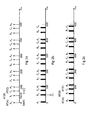
- FIG. 2a-2c schematically shows the time distribution of tasks performed within the co-operative system according to the invention.
- a 1 , A 2 etc. illustrates various time for communication unit A to perform the tasks described in conjunction to each of the figures 2a-2c.
- Figure 2a schematically shows the time distributed acquiring of raw data for communication units A, B and C.
- Figure 2b schematically shows the time distribution of the processing of the acquired raw data into an information package for communication units A, B and C.
- Figure 2c shows the time distribution for the broadcast attempts of the information packages for communication units A, B and C.
- Figures 2a-2c together shows a number of repetition cycles for performing the tasks of the invention for communication units A, B, C within each repetition cycle.
- the predetermined time period from start of the repetition cycle is of 100 ms.
- the acquisition of raw data from communication unit B is performed at even intervals starting at SnB
- the acquisition of raw data from communication unit C is performed at even intervals starting at SnC.
- the predetermined time period of each interval is in the example 100 ms but may be different depending of the setup of the method and/or the setup of the communication units A, B, C.
- the start of the interval for communication unit A, SnA may be at a time different from 0 ms.
- the intervals are synchronized by a global timing signal located in the raw data from the GNSS.
- an individual acquisition time for acquiring raw data D from the raw data collectors of the communication units is set for each of the plurality of communication units A, B, C.
- the individual acquisition times ATA, ATB, ATC for communication units A, B, C are shown.
- the individual acquisition times ATA, ATB, ATC may be randomly set as a delay from a start of a repetition, wherein said individual acquisition times ATA, ATB, ATC are set at each start up of a communication unit A, B, C.
- the individual acquisition time ATA, ATB, ATC may be set as a delay from a start of a repetition.
- the individual acquisition times of a first communication unit can be set dynamically dependent upon individual acquisition times of other communication units within a range allowing said other communication units to broadcast to said first communication unit. This is described best with reference to the instantaneous captured situation in figure 1 .
- communication unit A can receive the broadcasts from communication units B and C, whereby the individual acquisition time ATA of communication unit A is set dependent of the individual acquisition times ATB, ATC of communication units B and C.
- the acquisition time ATC of communication unit C is set dependent of the individual acquisition times ATA, ATB of communication units A and B.
- communication unit B is only within the broadcasting range TA of communication unit A, wherein the individual acquisition time ATB of communication unit B is set only dependent of the individual acquisition time ATA of communication unit A.
- the individual acquisition times ATA, ATB, ATC can be randomly set as a delay from each start of a repetition at production of said communication unit A, B, C.
- Figure 2b schematically shows the distribution time for processing of the raw data into information packages P.
- the width of the staples in figure 2b indicates the calculation time Ct needed to process the raw data.
- Figure 2c schematically shows the individual broadcasting times BTA, BTB, BTC for communication units A, B, C.
- the width of the staples in figure 2c indicates the distribution in time, at which the communication units try to broadcast their information packages.
- Figures 3a to 3c show a different embodiment of the invention.
- the processing of said raw data into an information package is executed directly after the acquiring of raw data.
- the said broadcast of said information package is executed at an individual broadcasting time BTA at a delay De1 from said start SnA of a repetition cycle.
- the delay De1 may be a universal delay for all communication units A, B, C. It is also possible for the communication units A, B, C to each have individual delays for the broadcasting times BTA, BTB, BTC.
- the individual acquisition times ATA, ATB, ATC may further be dependent on a calculation time Ct of said information package, which in figure 3b is indicated by the width of the staples.
- Figures 4a to 4c show a different embodiment of the invention.
- a broadcast of said information package is executed at an individual broadcasting time BTA from said start SnA of a repetition cycle.
- the individual acquisition time ATA is calculated as an offset O dependent of said individual broadcasting time BTA, such that said acquisition of raw data occurs before said broadcasting and at earliest at said start of a repetition.
- the processing of said raw data into an information package may be executed directly after the acquiring of raw data or be done with a delay.
- the same principle applies to all acquisition times in figure 4a.
- the offset O may be a universal offset for all communication units A, B, C. It is also possible for the communication units A, B, C to each have individual offsets for the acquisition times ATA, ATB, ATC.
- the delay times for the delays described above are set with a random delay algorithm.
Landscapes
- Engineering & Computer Science (AREA)
- Computer Networks & Wireless Communication (AREA)
- Signal Processing (AREA)
- Health & Medical Sciences (AREA)
- Computing Systems (AREA)
- General Health & Medical Sciences (AREA)
- Medical Informatics (AREA)
- Mobile Radio Communication Systems (AREA)
Abstract
• acquire raw data from at least one raw data collector,
• process said raw data into an information package, and
• broadcast of said information package.
Description
- The invention relates to the field of co-operative systems and especially a method to communicate within a co-operative system.
- A co-operative system comprises a plurality of communication units, which communicates in that they broadcast on a given wireless communication channel designated for the co-operative system. The communication units thereby broadcast information and receives information. The communication units can be integrated in vehicles and/or infrastructure in order to let the devices communicate with each other.
- Co-operative systems are used as traffic information systems to facilitate vehicle - vehicle and vehicle - infrastructure communication.
- One of the challenges in a co-operative system is that of the distribution information, i.e. the vehicle data that shall be broadcasted from every vehicle within a set interval.
- For example, the vehicles transmit their data once every 100 milliseconds (ms). The data is typically a time-stamped position, speed and heading of the vehicle, but can further comprise information from vehicle sensing means such as speed sensing means, acceleration sensing means, road conditions sensing means, weather condition sensing means, driver intention sensing means, etc.
- Normally the raw data is collected by a raw data collector, such as a global navigation satellite system (GNSS), or any other sensing means within a vehicle, such as speed sensing means, acceleration sensing means, road conditions sensing means, whether condition sensing means, driver intention sensing means, etc.
- The raw data is computed into an information package that can be broadcasted within the co-operative system. E.g. a GNSS receiver continuously receives a position signal from the GNSS, wherein this information is acquired by the communication unit, at the same time for each of the devices in the co-operative system. The information is fed into a position solution engine, which typically is a Kalman filter. The position solution is computed into the information packaged within fractions of a full second. The information package can include further information collected by other raw data collectors, whereby the information package thereby includes also this information.
- The time that it takes to compute the information package is not possible to predict precisely since it is dependent on many factors, such as amount of data and current speed of the device. Hence, there is a small range of time when the output from the position engine is given. When the output is ready, the data is included in a certain information package dedicated for broadcast in a co-operative system. This message is referred to as "Basic Safety Message" in the US and "Co-operative Awareness Message" in Europe, but will in the further text be referred to as information package.
- As soon as the information package is ready, the radio module tries to access the wireless communication channel of the co-operative system and broadcast the information package. Because all devices acquire their data at the a start of an interval and performs similar computations, there is an obvious risk that several devices tries to access the channel to broadcast their respective information packages at the same time, which will result in that some transmitters have to back off and try again later. The back-off and retry scheme is controlled by algorithms in the 802.11 standard and is outside the scope of this invention.
- In order to improve the accessibility to the communication channel, several different methods have been proposed to distribute the time on where the transmitters tries to access the wireless communication channel. One of those is called "Self Organized Time Division Multiple Access" where the devices are organized to transmit in a certain time slot, which is defined in an overall master frame. The master frame is distributed among the users without the interaction of a central station.
- When using "Self Organize Time Division Multiple Access" for example within a system with three devices, the devices are getting their information packages transmitted at a pre-defined time, but there is always a delay in time introduced between the finish of the computation, i.e. when the information package is ready to be send, and the broadcast of the information package. When the information package is actually broadcasted, the information package data in the information package has aged during the delay.
- By communicating aged data in the co-operative system, errors can occur and the relevance of the information in the system is decreased.
- It is desired to always broadcast as fresh data as possible in the information packages, an object of the invention is thereby to suggest a method for communication within a co-operative system, such that the information communicated within the system is as updated as possible during broadcast of the same.
- A co-operative system comprises a plurality of communication units, which communicates in that they broadcast on a given frequency. The method is adapted for a co-operative system in which a plurality of communication units are adapted to execute a group of tasks repeatedly, wherein at least one of the task is to broadcast at the frequency of the co-operative system. The tasks are repeated in repetition cycles. The communication units of in the co-operative system for which the method is adapted performs the following tasks:
- The communication unit acquire raw data from at least one raw data collector. The communication unit process the acquired raw data into an information package. The communication unit broadcast the information package at the frequency intended for the co-operative system.
- A raw data collector is at least a unit able to receive signals from a global navigation satellite system (GNSS), such that a position of the raw data collector, e.g. the vehicle, can be determined. The information from the GNSS also comprises a time stamp, i.e. global timing information to which the communication units synchronise. A raw data collector can further be any other sensing means within the vehicle, such as speed sensing means, acceleration sensing means, road conditions sensing means, whether condition sensing means, driver intention sensing means, etc.
- The repetition cycle lasts a predetermined time period from a start of a repetition cycle. For example, the communication units can be set to perform the task at least once every 100 millisecond (ms). The at least one raw data collector collects data at least from the GNSS. Because the different communication units within the co-operative system are synchronised to the global timing signal derived from the GNSS's global timing information, the cycle at which the communication units are to perform their tasks are synchronised.
- The inventive method assures a spread of the broadcasting in that each of the plurality of communication units is given an individual acquisition time for acquiring raw data from the raw data collectors. Because the communication units acquire their raw data at different times it is more likely that the channel is free when the communication unit has performed the computation of the information package and attempts to access the communication channel in order to broadcast.
- The method achieves a spread between when the different communication units acquire their raw data, whereby the following steps; processing the raw data into an information package and the thereafter broadcasting of the information package can follow immediately after the acquisition of raw data. The risk of that several communication units tries to broadcast simultaneously is reduced. With the inventive method the age of the broadcasted information is as low as possible, because there is no or a minimal waiting time between the acquisition, processing and the broadcasting. By implementing the inventive method it is enabled that the communication units always broadcasts as fresh information as possible, and further the risk for a broadcasting collision between a plurality of communication units within each other's broadcasting range is reduced considerably.
- To minimise the waiting time it is preferred that the processing of the raw data into an information package and the broadcast of the information package are executed directly after the preceding task.
- In an embodiment of the inventive method additionally to an individual acquisition time a delay time for broadcasting the information package is set for each of the plurality of communication units. The delay time is set as a delay from the start of a repetition cycle. The processing of raw data into an information package is however executed directly after the acquisition of raw data. The broadcast of said information package is thereby executed at a delay from the start of a repetition, wherein the lapsed time between the processing of raw data into an information package and the broadcast can vary depending of the time needed for the processing of raw data. An advantage with this embodiment is that each communication unit also becomes an individual broadcasting time, wherein the risk for collision in broadcasting can further reduced.
- In order to enable broadcasting information with as low age as possible when both an individual acquisition time and an individual broadcasting time (set as a delay from the start) is set, it is preferred that the individual acquisition time is calculated as an offset from said individual broadcasting time. The offset is calculated such that that the individually acquisition time occurs before said broadcast and at earliest at the start of a repetition. By making the individual acquisition time dependent on the individual broadcasting time, the time between the acquisition and the broadcast can be held down, wherein the age of the broadcasted information is as low as possible.
- It is further preferred that the calculation of the offset is dependent of both the processing speed of the communication unit and the delay for the broadcasting time. By implementing the offset of the individual acquisition time as dependent of the processing time for the communication unit and the delay of the broadcasting time the task can be performed essentially immediately after one another even though an individual broadcasting time is set for each communication unit.
- In an alternative embodiment the individual acquisition time is randomly set as a delay from a start of a repetition. The delay for the individual acquisition time can be set at each start up of a communication unit. Preferably a random delay algorithm is used therefore. An advantage with setting the delay for the acquisition at stat up of each communication unit is that the calculation must just be performed once for each start.
- In an alternative approach of setting the individual acquisition time, it is set as a delay from the start of a repetition cycle, wherein the individual acquisition time of a first communication unit is set dynamically dependent upon individual acquisition times of other communication units, within which broadcasting ranges the first communication unit is located. By setting the individual acquisition time dynamically and dependent on the individual acquisition times of the communication units that are within each other's broadcasting range, a controlled spread of the broadcasting can be achieved. Collisions between pluralities of broadcasts from different communication units can be avoided, because the broadcasts are indirectly delayed dependently of each other.
- Yet another alternative approach of setting the individual acquisition time is that it is set randomly as a delay or predetermined spread delay from each start of a repetition at production of said communication units. By setting a delay for the individual acquisition time already at production of said communication units, an even spread of the individual acquisition time can be assured within a batch of communication units.
- Communications units usually use a pseudo-id when communicating in a co-operative system. The pseudo-id is changed in regular or irregular intervals. In an alternative embodiment of the invention, the individual acquisition time is set in intervals corresponding to the interval of changes of a communication unit's pseudo-id. By changing the individual acquisition time together with the change of pseudo-id, a tracking of an individual communication unit becomes harder, wherein the integrity of the user of the communication unit is increased.
- The invention facilitates that as fresh data as possible is broadcasted within the co-operative network. However, even when the invention is implemented, it can occur that the channel is busy when a communication unit tries to broadcast its information package. If, a broadcast is unsuccessful, the communication unit backs-off and retries at a later stage. The back-off and retry scheme is controlled by algorithms in the 802.11 standard and is outside the scope of this invention.
-
-
Figure 1 schematically shows a co-operative system according to the invention, -
Figures 2a-2c schematically shows the time distribution of tasks performed within the co-operative system according to the invention. -
Figure 1 schematically shows a co-operative system CS according to the invention. The co-operative system comprises a plurality of communication units A, B, C. The communication units A, B, C can be of any type suitable to be active in the co-operative system CS, and be arranged in a vehicle or a road side unit. In the example all the communication units will be referred to as arranged in vehicles. - The vehicles in which communication units A, B, C in
figure 1 are located can all be travelling in the same direction, in different directions and/or on the same or on different roads. The communication units A, B, C broadcast on the frequency/channel designated for the co-operative system CS. The communication units A, B, C are all equipped with or have access to a raw data collector RC capable of receiving/sensing and processing the raw data D into an information package P. The communication units A, B, C are equipped with a radio communication unit arranged to communicate in the designated frequency/channel. - In
figure 1 the broadcast ranges TA, TB, TC of communication units A, B, C in the co-operative system are shown. Communication unit A has a broadcast range of TA, communication unit B has a broadcast range of TB and communication unit C has a broadcast range of TC. The communication units A, B, C infigure 1 have different broadcast ranges TA, TB, TC. A broadcast by the communication unit A can be received by both the communication units B and C. A broadcast of communication unit B can be received by communication unit A and C. A broadcast of communication unit C can be received by communication unit A. Due to the different broadcast range TA, TB, TC of the communication units A, B, C and the different distances between the communication units A, B, C not all communication units A, B, C are able to communicate with each other. However, the communication units A, B, C are adapted to be arranged in vehicles, whereby thefigure 1 only is an instantaneous situation of a dynamic reality. - Now,
figures 2a-2c schematically shows the time distribution of tasks performed within the co-operative system according to the invention. A1, A2 etc. illustrates various time for communication unit A to perform the tasks described in conjunction to each of thefigures 2a-2c. The same applies to communication units B and C. -
Figure 2a schematically shows the time distributed acquiring of raw data for communication units A, B and C.Figure 2b schematically shows the time distribution of the processing of the acquired raw data into an information package for communication units A, B and C.Figure 2c shows the time distribution for the broadcast attempts of the information packages for communication units A, B and C.Figures 2a-2c together shows a number of repetition cycles for performing the tasks of the invention for communication units A, B, C within each repetition cycle. - In
figure 2a the acquisition of raw data from communication unit A is performed at even intervals starting at SnA=0 ms. The predetermined time period from start of the repetition cycle is of 100 ms. The acquisition of raw data from communication unit B is performed at even intervals starting at SnB The acquisition of raw data from communication unit C is performed at even intervals starting at SnC. The predetermined time period of each interval is in the example 100 ms but may be different depending of the setup of the method and/or the setup of the communication units A, B, C. The start of the interval for communication unit A, SnA, may be at a time different from 0 ms. - The intervals are synchronized by a global timing signal located in the raw data from the GNSS. As can be seen from
figure 2a an individual acquisition time for acquiring raw data D from the raw data collectors of the communication units is set for each of the plurality of communication units A, B, C. Infigure 2a the individual acquisition times ATA, ATB, ATC for communication units A, B, C are shown. The individual acquisition times ATA, ATB, ATC may be randomly set as a delay from a start of a repetition, wherein said individual acquisition times ATA, ATB, ATC are set at each start up of a communication unit A, B, C. Alternatively the individual acquisition time ATA, ATB, ATC may be set as a delay from a start of a repetition. The individual acquisition times of a first communication unit can be set dynamically dependent upon individual acquisition times of other communication units within a range allowing said other communication units to broadcast to said first communication unit. This is described best with reference to the instantaneous captured situation infigure 1 . In the situation disclosed infigure 1 , communication unit A can receive the broadcasts from communication units B and C, whereby the individual acquisition time ATA of communication unit A is set dependent of the individual acquisition times ATB, ATC of communication units B and C. Correspondently, the acquisition time ATC of communication unit C is set dependent of the individual acquisition times ATA, ATB of communication units A and B. However, communication unit B is only within the broadcasting range TA of communication unit A, wherein the individual acquisition time ATB of communication unit B is set only dependent of the individual acquisition time ATA of communication unit A. - Further, the individual acquisition times ATA, ATB, ATC can be randomly set as a delay from each start of a repetition at production of said communication unit A, B, C.
-
Figure 2b schematically shows the distribution time for processing of the raw data into information packages P. The width of the staples infigure 2b indicates the calculation time Ct needed to process the raw data.Figure 2c schematically shows the individual broadcasting times BTA, BTB, BTC for communication units A, B, C. The width of the staples infigure 2c indicates the distribution in time, at which the communication units try to broadcast their information packages. - In
figures 2b and 2c the task of processing raw data into an information package, and broadcasting said information package are executed directly after the preceding task. There are thus no delays between the task of acquiring raw data A1 infigure 2a and the processing task A1 infigure 2b or between the processing task A1 infigure 2b and the broadcasting task A1 infigure 2c . The same principle applies to all tasks infigures 2a-2c. -
Figures 3a to 3c show a different embodiment of the invention. Infigure 3b the processing of said raw data into an information package is executed directly after the acquiring of raw data. Infigure 3c the said broadcast of said information package is executed at an individual broadcasting time BTA at a delay De1 from said start SnA of a repetition cycle. Infigure 3 only one individual broadcasting time is shown. The same principle applies to all broadcasting times infigure 3c . The delay De1 may be a universal delay for all communication units A, B, C. It is also possible for the communication units A, B, C to each have individual delays for the broadcasting times BTA, BTB, BTC. The individual acquisition times ATA, ATB, ATC may further be dependent on a calculation time Ct of said information package, which infigure 3b is indicated by the width of the staples. -
Figures 4a to 4c show a different embodiment of the invention. Infigure 4c a broadcast of said information package is executed at an individual broadcasting time BTA from said start SnA of a repetition cycle. Infigure 4a the individual acquisition time ATA is calculated as an offset O dependent of said individual broadcasting time BTA, such that said acquisition of raw data occurs before said broadcasting and at earliest at said start of a repetition. The processing of said raw data into an information package may be executed directly after the acquiring of raw data or be done with a delay. The same principle applies to all acquisition times infigure 4a. The offset O may be a universal offset for all communication units A, B, C. It is also possible for the communication units A, B, C to each have individual offsets for the acquisition times ATA, ATB, ATC. - The delay times for the delays described above are set with a random delay algorithm.
- In
figures 2a-4c what is described for one time period applies to all time periods of the same embodiment. It is also possible to switch between the embodiments shown infigures 2a-2c, 3a-3c and4a-4c. - Reference signs mentioned in the claims should not be seen as limiting the extent of the matter protected by the claims, and their sole function is to make claims easier to understand.
- As will be realised, the invention is capable of modification in various obvious respects, all without departing from the scope of the appended claims. Accordingly, the drawings and the description are to be regarded as illustrative in nature, and not restrictive.
Claims (9)
- A method for communication within a co-operative system (CS) said co-operative system (CS) comprises a plurality of communication units (A, B, C), which are adapted to execute a group of tasks repeatedly in a repetition cycle:• acquire raw data from at least one raw data collector,• process said raw data into an information package, and• broadcast of said information package,
wherein said repetition cycle lasts a predetermined time period from a start (SnA, SnB, SnC) of a repetition cycle, and said at least one raw data collector collects data from a global navigation satellite system (GNSS), and wherein said raw data from the GNSS comprises a global timing information, to which said communication units (A, B, C) synchronise and wherein a timing of said execution of tasks is dependent of said global timing signal (TS), characterised in, that
an individual acquisition time (ATA, ATB, ATC) for acquiring raw data from the raw data collectors is set for each of the plurality of communication units (A, B, C). - Method according to claim 1, wherein said processing of said raw data into an information package and said broadcast of said information package are executed directly after the preceding task.
- Method according to claim 1, wherein said processing of said raw data into an information package is executed directly after the acquiring of raw data, and said broadcast of said information package is executed at an individual broadcasting time (BTA, BTB, BTC) at a delay (De1) from said start (SnA, SnB, SnC) of a repetition cycle.
- Method according to claim 3, wherein said individual acquisition time (ATA, ATB, ATC) is calculated as an offset (O) dependent of said individual broadcasting time (BT), such that said acquisition of raw data occurs before said broadcasting and at earliest at said start of a repetition.
- Method according to claim 3, wherein said individually acquisition time (ATA, ATB, ATC) is further dependent on a calculation time (Ct) of said information package (P).
- Method according to claim 1 or 2, wherein said individual acquisition time (ATA, ATB, ATC) is randomly set as a delay from a start of a repetition, wherein said individual acquisition time (ATA, ATB, ATC) is set at each start up of a communication unit (A, B, C).
- Method according to claim 1 or 2, wherein said individual acquisition time (ATA, ATB, ATC) is set as a delay from a start of a repetition, wherein said individual acquisition time (ATA, ATB, ATC) of a first communication unit (A, B, C) is set dynamically dependent upon individual acquisition times (ATA, ATB, ATC) of other communication units (A, B, C) located within a broadcasting range of said first communication unit (A, B, C).
- Method according to claim 1 or 2, wherein said individual acquisition time (ATA, ATB, ATC) is randomly set as an delay from each start of a repetition at production of said communication unit (A, B, C).
- Method according to claim 1 or 2, wherein said individual acquisition time (ATA, ATB, ATC) is randomly set as a delay from each start of a repetition at each change of pseudo-ID of said communication unit (A, B, C).
Priority Applications (4)
| Application Number | Priority Date | Filing Date | Title |
|---|---|---|---|
| EP13158657.0A EP2778802B1 (en) | 2013-03-11 | 2013-03-11 | A method for communication within a co-operative system |
| ES13158657T ES2752230T3 (en) | 2013-03-11 | 2013-03-11 | A method of communication within a cooperative system |
| CA2845295A CA2845295C (en) | 2013-03-11 | 2014-03-11 | A method for communication within a co-operative system |
| US14/204,861 US9768972B2 (en) | 2013-03-11 | 2014-03-11 | Method for communication within a co-operative system |
Applications Claiming Priority (1)
| Application Number | Priority Date | Filing Date | Title |
|---|---|---|---|
| EP13158657.0A EP2778802B1 (en) | 2013-03-11 | 2013-03-11 | A method for communication within a co-operative system |
Publications (2)
| Publication Number | Publication Date |
|---|---|
| EP2778802A1 true EP2778802A1 (en) | 2014-09-17 |
| EP2778802B1 EP2778802B1 (en) | 2019-07-31 |
Family
ID=47891420
Family Applications (1)
| Application Number | Title | Priority Date | Filing Date |
|---|---|---|---|
| EP13158657.0A Active EP2778802B1 (en) | 2013-03-11 | 2013-03-11 | A method for communication within a co-operative system |
Country Status (4)
| Country | Link |
|---|---|
| US (1) | US9768972B2 (en) |
| EP (1) | EP2778802B1 (en) |
| CA (1) | CA2845295C (en) |
| ES (1) | ES2752230T3 (en) |
Cited By (2)
| Publication number | Priority date | Publication date | Assignee | Title |
|---|---|---|---|---|
| CN104735683A (en) * | 2015-03-24 | 2015-06-24 | 浙江大学 | RSU arrangement method oriented to information collection time delay guarantee in urban road network |
| CN109479249A (en) * | 2016-08-05 | 2019-03-15 | 株式会社Ntt都科摩 | Uplink data transmission method and device |
Families Citing this family (3)
| Publication number | Priority date | Publication date | Assignee | Title |
|---|---|---|---|---|
| CN108243390B (en) * | 2016-12-26 | 2019-08-16 | 电信科学技术研究院 | A kind of method and terminal synchronized |
| EP3855773B1 (en) * | 2018-09-20 | 2023-08-09 | Beijing Xiaomi Mobile Software Co., Ltd. | Vehicle-to-everything synchronization method and device |
| CN112666820B (en) * | 2020-12-07 | 2022-03-08 | 腾讯科技(深圳)有限公司 | Time correction method, terminal device, electronic device, and storage medium |
Citations (3)
| Publication number | Priority date | Publication date | Assignee | Title |
|---|---|---|---|---|
| US5319374A (en) * | 1993-02-02 | 1994-06-07 | Trimble Navigation Limited | Precise universal time for vehicles |
| FR2746533A1 (en) * | 1996-03-25 | 1997-09-26 | Electricite De France | Data collection procedure for non-wired sensors such as in heating system |
| FR2785112A1 (en) * | 1998-10-21 | 2000-04-28 | Dassault Electronique | EMBEDDED BEACON, PARTICULARLY FOR THE MANAGEMENT OF VEHICLE FLEETS |
Family Cites Families (6)
| Publication number | Priority date | Publication date | Assignee | Title |
|---|---|---|---|---|
| RU2108627C1 (en) * | 1991-07-01 | 1998-04-10 | Ланс Хокан | Position indicating system |
| KR101086072B1 (en) * | 2004-09-18 | 2011-11-22 | 삼성전자주식회사 | Terminal Location Determination Method Using APS Information |
| US20060176896A1 (en) * | 2005-02-10 | 2006-08-10 | Callaway Edgar H Jr | Method and apparatus for transmitting data within a communication system |
| JP5193495B2 (en) * | 2007-05-07 | 2013-05-08 | 株式会社ブリヂストン | Tire pressure information measuring device |
| US8265624B2 (en) * | 2007-09-24 | 2012-09-11 | Kapsch Trafficcom Ag | Method and system for broadcast message transmission in mobile systems |
| WO2011066473A1 (en) * | 2009-11-25 | 2011-06-03 | Maxlinear, Inc. | Co-operative geolocation |
-
2013
- 2013-03-11 EP EP13158657.0A patent/EP2778802B1/en active Active
- 2013-03-11 ES ES13158657T patent/ES2752230T3/en active Active
-
2014
- 2014-03-11 US US14/204,861 patent/US9768972B2/en active Active
- 2014-03-11 CA CA2845295A patent/CA2845295C/en active Active
Patent Citations (3)
| Publication number | Priority date | Publication date | Assignee | Title |
|---|---|---|---|---|
| US5319374A (en) * | 1993-02-02 | 1994-06-07 | Trimble Navigation Limited | Precise universal time for vehicles |
| FR2746533A1 (en) * | 1996-03-25 | 1997-09-26 | Electricite De France | Data collection procedure for non-wired sensors such as in heating system |
| FR2785112A1 (en) * | 1998-10-21 | 2000-04-28 | Dassault Electronique | EMBEDDED BEACON, PARTICULARLY FOR THE MANAGEMENT OF VEHICLE FLEETS |
Cited By (4)
| Publication number | Priority date | Publication date | Assignee | Title |
|---|---|---|---|---|
| CN104735683A (en) * | 2015-03-24 | 2015-06-24 | 浙江大学 | RSU arrangement method oriented to information collection time delay guarantee in urban road network |
| CN104735683B (en) * | 2015-03-24 | 2018-05-22 | 浙江大学 | Information collects the RSU method for arranging of delay guarantee in a kind of urban road network |
| CN109479249A (en) * | 2016-08-05 | 2019-03-15 | 株式会社Ntt都科摩 | Uplink data transmission method and device |
| CN109479249B (en) * | 2016-08-05 | 2021-07-16 | 株式会社Ntt都科摩 | Uplink data transmission method and device |
Also Published As
| Publication number | Publication date |
|---|---|
| EP2778802B1 (en) | 2019-07-31 |
| US9768972B2 (en) | 2017-09-19 |
| ES2752230T3 (en) | 2020-04-03 |
| US20140254480A1 (en) | 2014-09-11 |
| CA2845295A1 (en) | 2014-09-11 |
| CA2845295C (en) | 2020-06-23 |
Similar Documents
| Publication | Publication Date | Title |
|---|---|---|
| CA2845295C (en) | A method for communication within a co-operative system | |
| US9450691B2 (en) | Method and device for synchronizing network subscribers in an on-board network of a vehicle | |
| US9147294B1 (en) | Apparatus and method for intelligent channel switching to support V2X communication | |
| US20200118436A1 (en) | Safety event message transmission timing in dedicated short-range communication (dsrc) | |
| US9173196B2 (en) | Adaptive multi-channel access for vehicular networks | |
| EP2375834B1 (en) | Maintaining time of day synchronization | |
| EP3457381A1 (en) | Vehicle control system and vehicle control device | |
| CN114375052B (en) | Communication method and device | |
| CN107316348A (en) | Disturbance restraining method, electronic charging system without parking and road side unit equipment | |
| US20120236841A1 (en) | Base station apparatus for transmitting or receiving a signal including predetermined information | |
| EP3072342B1 (en) | Channel access in a vehicular communication network | |
| EP3223492A1 (en) | Terminal device for vehicle-to-vehicle communication | |
| CN117500044A (en) | Anti-collision method of positioning system based on UWB TOF ranging | |
| US20120040703A1 (en) | Broadcasting method, access control apparatus and radio apparatus | |
| JP5799238B1 (en) | Wireless device, processing device, and processing system | |
| JP2010154309A (en) | Announcement method and radio device | |
| US8971297B2 (en) | Broadcasting method, access control apparatus, and terminal apparatus | |
| CN116032403B (en) | Methods, devices, equipment and storage media for timing synchronization of vehicle-mounted equipment | |
| JP2020102705A (en) | Semiconductor device, wireless terminal device, wireless communication system, and communication method of wireless terminal device | |
| US10499422B2 (en) | Wireless communication apparatus and wireless communication system | |
| JP2020141417A (en) | Roadside communicators, packet transmission methods, and computer programs | |
| US11521490B2 (en) | Semiconductor device, radio terminal device, and communication method of radio terminal device | |
| JP2004166133A (en) | District polling method | |
| EP4331314A1 (en) | A vehicular wireless channel access method | |
| JP2011182138A (en) | Base station device and terminal device |
Legal Events
| Date | Code | Title | Description |
|---|---|---|---|
| PUAI | Public reference made under article 153(3) epc to a published international application that has entered the european phase |
Free format text: ORIGINAL CODE: 0009012 |
|
| 17P | Request for examination filed |
Effective date: 20130311 |
|
| AK | Designated contracting states |
Kind code of ref document: A1 Designated state(s): AL AT BE BG CH CY CZ DE DK EE ES FI FR GB GR HR HU IE IS IT LI LT LU LV MC MK MT NL NO PL PT RO RS SE SI SK SM TR |
|
| AX | Request for extension of the european patent |
Extension state: BA ME |
|
| R17P | Request for examination filed (corrected) |
Effective date: 20150313 |
|
| RBV | Designated contracting states (corrected) |
Designated state(s): AL AT BE BG CH CY CZ DE DK EE ES FI FR GB GR HR HU IE IS IT LI LT LU LV MC MK MT NL NO PL PT RO RS SE SI SK SM TR |
|
| STAA | Information on the status of an ep patent application or granted ep patent |
Free format text: STATUS: EXAMINATION IS IN PROGRESS |
|
| 17Q | First examination report despatched |
Effective date: 20170804 |
|
| REG | Reference to a national code |
Ref country code: DE Ref legal event code: R079 Ref document number: 602013058399 Country of ref document: DE Free format text: PREVIOUS MAIN CLASS: G04R0020020000 Ipc: H04L0012180000 |
|
| GRAP | Despatch of communication of intention to grant a patent |
Free format text: ORIGINAL CODE: EPIDOSNIGR1 |
|
| STAA | Information on the status of an ep patent application or granted ep patent |
Free format text: STATUS: GRANT OF PATENT IS INTENDED |
|
| RIC1 | Information provided on ipc code assigned before grant |
Ipc: G04R 20/02 20130101ALI20190201BHEP Ipc: H04L 29/08 20060101ALI20190201BHEP Ipc: H04L 12/18 20060101AFI20190201BHEP |
|
| INTG | Intention to grant announced |
Effective date: 20190226 |
|
| GRAS | Grant fee paid |
Free format text: ORIGINAL CODE: EPIDOSNIGR3 |
|
| GRAA | (expected) grant |
Free format text: ORIGINAL CODE: 0009210 |
|
| STAA | Information on the status of an ep patent application or granted ep patent |
Free format text: STATUS: THE PATENT HAS BEEN GRANTED |
|
| AK | Designated contracting states |
Kind code of ref document: B1 Designated state(s): AL AT BE BG CH CY CZ DE DK EE ES FI FR GB GR HR HU IE IS IT LI LT LU LV MC MK MT NL NO PL PT RO RS SE SI SK SM TR |
|
| REG | Reference to a national code |
Ref country code: CH Ref legal event code: EP Ref country code: GB Ref legal event code: FG4D |
|
| REG | Reference to a national code |
Ref country code: DE Ref legal event code: R096 Ref document number: 602013058399 Country of ref document: DE |
|
| REG | Reference to a national code |
Ref country code: AT Ref legal event code: REF Ref document number: 1162130 Country of ref document: AT Kind code of ref document: T Effective date: 20190815 |
|
| REG | Reference to a national code |
Ref country code: IE Ref legal event code: FG4D |
|
| REG | Reference to a national code |
Ref country code: SE Ref legal event code: TRGR |
|
| REG | Reference to a national code |
Ref country code: NL Ref legal event code: MP Effective date: 20190731 |
|
| REG | Reference to a national code |
Ref country code: LT Ref legal event code: MG4D |
|
| PG25 | Lapsed in a contracting state [announced via postgrant information from national office to epo] |
Ref country code: FI Free format text: LAPSE BECAUSE OF FAILURE TO SUBMIT A TRANSLATION OF THE DESCRIPTION OR TO PAY THE FEE WITHIN THE PRESCRIBED TIME-LIMIT Effective date: 20190731 Ref country code: HR Free format text: LAPSE BECAUSE OF FAILURE TO SUBMIT A TRANSLATION OF THE DESCRIPTION OR TO PAY THE FEE WITHIN THE PRESCRIBED TIME-LIMIT Effective date: 20190731 Ref country code: LT Free format text: LAPSE BECAUSE OF FAILURE TO SUBMIT A TRANSLATION OF THE DESCRIPTION OR TO PAY THE FEE WITHIN THE PRESCRIBED TIME-LIMIT Effective date: 20190731 Ref country code: NL Free format text: LAPSE BECAUSE OF FAILURE TO SUBMIT A TRANSLATION OF THE DESCRIPTION OR TO PAY THE FEE WITHIN THE PRESCRIBED TIME-LIMIT Effective date: 20190731 Ref country code: BG Free format text: LAPSE BECAUSE OF FAILURE TO SUBMIT A TRANSLATION OF THE DESCRIPTION OR TO PAY THE FEE WITHIN THE PRESCRIBED TIME-LIMIT Effective date: 20191031 Ref country code: PT Free format text: LAPSE BECAUSE OF FAILURE TO SUBMIT A TRANSLATION OF THE DESCRIPTION OR TO PAY THE FEE WITHIN THE PRESCRIBED TIME-LIMIT Effective date: 20191202 Ref country code: NO Free format text: LAPSE BECAUSE OF FAILURE TO SUBMIT A TRANSLATION OF THE DESCRIPTION OR TO PAY THE FEE WITHIN THE PRESCRIBED TIME-LIMIT Effective date: 20191031 |
|
| PG25 | Lapsed in a contracting state [announced via postgrant information from national office to epo] |
Ref country code: AL Free format text: LAPSE BECAUSE OF FAILURE TO SUBMIT A TRANSLATION OF THE DESCRIPTION OR TO PAY THE FEE WITHIN THE PRESCRIBED TIME-LIMIT Effective date: 20190731 Ref country code: GR Free format text: LAPSE BECAUSE OF FAILURE TO SUBMIT A TRANSLATION OF THE DESCRIPTION OR TO PAY THE FEE WITHIN THE PRESCRIBED TIME-LIMIT Effective date: 20191101 Ref country code: RS Free format text: LAPSE BECAUSE OF FAILURE TO SUBMIT A TRANSLATION OF THE DESCRIPTION OR TO PAY THE FEE WITHIN THE PRESCRIBED TIME-LIMIT Effective date: 20190731 Ref country code: LV Free format text: LAPSE BECAUSE OF FAILURE TO SUBMIT A TRANSLATION OF THE DESCRIPTION OR TO PAY THE FEE WITHIN THE PRESCRIBED TIME-LIMIT Effective date: 20190731 Ref country code: IS Free format text: LAPSE BECAUSE OF FAILURE TO SUBMIT A TRANSLATION OF THE DESCRIPTION OR TO PAY THE FEE WITHIN THE PRESCRIBED TIME-LIMIT Effective date: 20191130 |
|
| PG25 | Lapsed in a contracting state [announced via postgrant information from national office to epo] |
Ref country code: TR Free format text: LAPSE BECAUSE OF FAILURE TO SUBMIT A TRANSLATION OF THE DESCRIPTION OR TO PAY THE FEE WITHIN THE PRESCRIBED TIME-LIMIT Effective date: 20190731 |
|
| PG25 | Lapsed in a contracting state [announced via postgrant information from national office to epo] |
Ref country code: PL Free format text: LAPSE BECAUSE OF FAILURE TO SUBMIT A TRANSLATION OF THE DESCRIPTION OR TO PAY THE FEE WITHIN THE PRESCRIBED TIME-LIMIT Effective date: 20190731 Ref country code: EE Free format text: LAPSE BECAUSE OF FAILURE TO SUBMIT A TRANSLATION OF THE DESCRIPTION OR TO PAY THE FEE WITHIN THE PRESCRIBED TIME-LIMIT Effective date: 20190731 Ref country code: DK Free format text: LAPSE BECAUSE OF FAILURE TO SUBMIT A TRANSLATION OF THE DESCRIPTION OR TO PAY THE FEE WITHIN THE PRESCRIBED TIME-LIMIT Effective date: 20190731 Ref country code: IT Free format text: LAPSE BECAUSE OF FAILURE TO SUBMIT A TRANSLATION OF THE DESCRIPTION OR TO PAY THE FEE WITHIN THE PRESCRIBED TIME-LIMIT Effective date: 20190731 Ref country code: RO Free format text: LAPSE BECAUSE OF FAILURE TO SUBMIT A TRANSLATION OF THE DESCRIPTION OR TO PAY THE FEE WITHIN THE PRESCRIBED TIME-LIMIT Effective date: 20190731 |
|
| PG25 | Lapsed in a contracting state [announced via postgrant information from national office to epo] |
Ref country code: SK Free format text: LAPSE BECAUSE OF FAILURE TO SUBMIT A TRANSLATION OF THE DESCRIPTION OR TO PAY THE FEE WITHIN THE PRESCRIBED TIME-LIMIT Effective date: 20190731 Ref country code: SM Free format text: LAPSE BECAUSE OF FAILURE TO SUBMIT A TRANSLATION OF THE DESCRIPTION OR TO PAY THE FEE WITHIN THE PRESCRIBED TIME-LIMIT Effective date: 20190731 Ref country code: IS Free format text: LAPSE BECAUSE OF FAILURE TO SUBMIT A TRANSLATION OF THE DESCRIPTION OR TO PAY THE FEE WITHIN THE PRESCRIBED TIME-LIMIT Effective date: 20200224 Ref country code: CZ Free format text: LAPSE BECAUSE OF FAILURE TO SUBMIT A TRANSLATION OF THE DESCRIPTION OR TO PAY THE FEE WITHIN THE PRESCRIBED TIME-LIMIT Effective date: 20190731 |
|
| REG | Reference to a national code |
Ref country code: DE Ref legal event code: R097 Ref document number: 602013058399 Country of ref document: DE |
|
| PLBE | No opposition filed within time limit |
Free format text: ORIGINAL CODE: 0009261 |
|
| STAA | Information on the status of an ep patent application or granted ep patent |
Free format text: STATUS: NO OPPOSITION FILED WITHIN TIME LIMIT |
|
| PG2D | Information on lapse in contracting state deleted |
Ref country code: IS |
|
| PG25 | Lapsed in a contracting state [announced via postgrant information from national office to epo] |
Ref country code: IS Free format text: LAPSE BECAUSE OF FAILURE TO SUBMIT A TRANSLATION OF THE DESCRIPTION OR TO PAY THE FEE WITHIN THE PRESCRIBED TIME-LIMIT Effective date: 20191030 |
|
| 26N | No opposition filed |
Effective date: 20200603 |
|
| PG25 | Lapsed in a contracting state [announced via postgrant information from national office to epo] |
Ref country code: SI Free format text: LAPSE BECAUSE OF FAILURE TO SUBMIT A TRANSLATION OF THE DESCRIPTION OR TO PAY THE FEE WITHIN THE PRESCRIBED TIME-LIMIT Effective date: 20190731 |
|
| PG25 | Lapsed in a contracting state [announced via postgrant information from national office to epo] |
Ref country code: MC Free format text: LAPSE BECAUSE OF FAILURE TO SUBMIT A TRANSLATION OF THE DESCRIPTION OR TO PAY THE FEE WITHIN THE PRESCRIBED TIME-LIMIT Effective date: 20190731 |
|
| REG | Reference to a national code |
Ref country code: CH Ref legal event code: PL |
|
| REG | Reference to a national code |
Ref country code: BE Ref legal event code: MM Effective date: 20200331 |
|
| PG25 | Lapsed in a contracting state [announced via postgrant information from national office to epo] |
Ref country code: LU Free format text: LAPSE BECAUSE OF NON-PAYMENT OF DUE FEES Effective date: 20200311 |
|
| PG25 | Lapsed in a contracting state [announced via postgrant information from national office to epo] |
Ref country code: IE Free format text: LAPSE BECAUSE OF NON-PAYMENT OF DUE FEES Effective date: 20200311 Ref country code: LI Free format text: LAPSE BECAUSE OF NON-PAYMENT OF DUE FEES Effective date: 20200331 Ref country code: CH Free format text: LAPSE BECAUSE OF NON-PAYMENT OF DUE FEES Effective date: 20200331 |
|
| PG25 | Lapsed in a contracting state [announced via postgrant information from national office to epo] |
Ref country code: BE Free format text: LAPSE BECAUSE OF NON-PAYMENT OF DUE FEES Effective date: 20200331 |
|
| GBPC | Gb: european patent ceased through non-payment of renewal fee |
Effective date: 20200311 |
|
| PG25 | Lapsed in a contracting state [announced via postgrant information from national office to epo] |
Ref country code: GB Free format text: LAPSE BECAUSE OF NON-PAYMENT OF DUE FEES Effective date: 20200311 |
|
| REG | Reference to a national code |
Ref country code: AT Ref legal event code: UEP Ref document number: 1162130 Country of ref document: AT Kind code of ref document: T Effective date: 20190731 |
|
| PG25 | Lapsed in a contracting state [announced via postgrant information from national office to epo] |
Ref country code: MT Free format text: LAPSE BECAUSE OF FAILURE TO SUBMIT A TRANSLATION OF THE DESCRIPTION OR TO PAY THE FEE WITHIN THE PRESCRIBED TIME-LIMIT Effective date: 20190731 Ref country code: CY Free format text: LAPSE BECAUSE OF FAILURE TO SUBMIT A TRANSLATION OF THE DESCRIPTION OR TO PAY THE FEE WITHIN THE PRESCRIBED TIME-LIMIT Effective date: 20190731 |
|
| PG25 | Lapsed in a contracting state [announced via postgrant information from national office to epo] |
Ref country code: MK Free format text: LAPSE BECAUSE OF FAILURE TO SUBMIT A TRANSLATION OF THE DESCRIPTION OR TO PAY THE FEE WITHIN THE PRESCRIBED TIME-LIMIT Effective date: 20190731 |
|
| P01 | Opt-out of the competence of the unified patent court (upc) registered |
Effective date: 20230513 |
|
| REG | Reference to a national code |
Ref country code: DE Ref legal event code: R081 Ref document number: 602013058399 Country of ref document: DE Owner name: KAPSCH TRAFFICCOM AG, AT Free format text: FORMER OWNER: KAPSCH TRAFFICCOM AB, JOENKOEPING, SE |
|
| REG | Reference to a national code |
Ref country code: ES Ref legal event code: PC2A Owner name: KAPSCH TRAFFICCOM AG Effective date: 20241118 |
|
| REG | Reference to a national code |
Ref country code: AT Ref legal event code: PC Ref document number: 1162130 Country of ref document: AT Kind code of ref document: T Owner name: KAPSCH TRAFFICCOM AG, AT Effective date: 20241024 |
|
| PGFP | Annual fee paid to national office [announced via postgrant information from national office to epo] |
Ref country code: SE Payment date: 20260319 Year of fee payment: 14 |
|
| PGFP | Annual fee paid to national office [announced via postgrant information from national office to epo] |
Ref country code: DE Payment date: 20260319 Year of fee payment: 14 |
|
| PGFP | Annual fee paid to national office [announced via postgrant information from national office to epo] |
Ref country code: AT Payment date: 20260320 Year of fee payment: 14 |
|
| PGFP | Annual fee paid to national office [announced via postgrant information from national office to epo] |
Ref country code: FR Payment date: 20260320 Year of fee payment: 14 |
|
| PGFP | Annual fee paid to national office [announced via postgrant information from national office to epo] |
Ref country code: ES Payment date: 20260424 Year of fee payment: 14 |