EP2778541B1 - Circuit for decreasing the primary return temperature in district heating systems - Google Patents
Circuit for decreasing the primary return temperature in district heating systems Download PDFInfo
- Publication number
- EP2778541B1 EP2778541B1 EP13159617.3A EP13159617A EP2778541B1 EP 2778541 B1 EP2778541 B1 EP 2778541B1 EP 13159617 A EP13159617 A EP 13159617A EP 2778541 B1 EP2778541 B1 EP 2778541B1
- Authority
- EP
- European Patent Office
- Prior art keywords
- transfer medium
- heat transfer
- heat
- pipe system
- heat exchanger
- Prior art date
- Legal status (The legal status is an assumption and is not a legal conclusion. Google has not performed a legal analysis and makes no representation as to the accuracy of the status listed.)
- Not-in-force
Links
Images


Classifications
-
- F—MECHANICAL ENGINEERING; LIGHTING; HEATING; WEAPONS; BLASTING
- F24—HEATING; RANGES; VENTILATING
- F24D—DOMESTIC- OR SPACE-HEATING SYSTEMS, e.g. CENTRAL HEATING SYSTEMS; DOMESTIC HOT-WATER SUPPLY SYSTEMS; ELEMENTS OR COMPONENTS THEREFOR
- F24D10/00—District heating systems
- F24D10/003—Domestic delivery stations having a heat exchanger
-
- F—MECHANICAL ENGINEERING; LIGHTING; HEATING; WEAPONS; BLASTING
- F24—HEATING; RANGES; VENTILATING
- F24D—DOMESTIC- OR SPACE-HEATING SYSTEMS, e.g. CENTRAL HEATING SYSTEMS; DOMESTIC HOT-WATER SUPPLY SYSTEMS; ELEMENTS OR COMPONENTS THEREFOR
- F24D17/00—Domestic hot-water supply systems
- F24D17/0015—Domestic hot-water supply systems using solar energy
- F24D17/0021—Domestic hot-water supply systems using solar energy with accumulation of the heated water
-
- Y—GENERAL TAGGING OF NEW TECHNOLOGICAL DEVELOPMENTS; GENERAL TAGGING OF CROSS-SECTIONAL TECHNOLOGIES SPANNING OVER SEVERAL SECTIONS OF THE IPC; TECHNICAL SUBJECTS COVERED BY FORMER USPC CROSS-REFERENCE ART COLLECTIONS [XRACs] AND DIGESTS
- Y02—TECHNOLOGIES OR APPLICATIONS FOR MITIGATION OR ADAPTATION AGAINST CLIMATE CHANGE
- Y02B—CLIMATE CHANGE MITIGATION TECHNOLOGIES RELATED TO BUILDINGS, e.g. HOUSING, HOUSE APPLIANCES OR RELATED END-USER APPLICATIONS
- Y02B30/00—Energy efficient heating, ventilation or air conditioning [HVAC]
- Y02B30/17—District heating
-
- Y—GENERAL TAGGING OF NEW TECHNOLOGICAL DEVELOPMENTS; GENERAL TAGGING OF CROSS-SECTIONAL TECHNOLOGIES SPANNING OVER SEVERAL SECTIONS OF THE IPC; TECHNICAL SUBJECTS COVERED BY FORMER USPC CROSS-REFERENCE ART COLLECTIONS [XRACs] AND DIGESTS
- Y02—TECHNOLOGIES OR APPLICATIONS FOR MITIGATION OR ADAPTATION AGAINST CLIMATE CHANGE
- Y02E—REDUCTION OF GREENHOUSE GAS [GHG] EMISSIONS, RELATED TO ENERGY GENERATION, TRANSMISSION OR DISTRIBUTION
- Y02E20/00—Combustion technologies with mitigation potential
- Y02E20/14—Combined heat and power generation [CHP]
Definitions
- the invention relates to a pipeline system according to the preamble of claim 1 and to a method for heating heat transfer medium in a heat pipe system of a pipeline system according to claim 11.
- piping systems which have a first heat pipe system which draws heat from the district heating network supply and returns a heat transfer medium cooled by heat extraction into the district heating network return of the district heating network.
- part of such a piping system is a second heat pipe system, which removes heat from the first heat pipe system via a heat exchanger in order to heat a second heat transfer medium.
- the first heat transfer medium cools in the first heat pipe system.
- Such a piping system is for example from the EP 1 455 140 A1 known.
- this document teaches a multi-stage water heating.
- a second heat transfer medium in this case drinking water, is raised in response to the temperature of the primary return to a corresponding temperature level.
- the temperature of the second heat transfer medium can be thermally raised after passing through the preheater by serving as an intermediate heat exchanger heat exchanger.
- the intermediate heater can also be designed as a solar system.
- a reheater raises the temperature of the second heat transfer medium to target temperature for a hot water supply.
- a first heat exchanger is used for heating a heating circuit
- a second and a third heat exchanger are used in cascade for DHW heating. They transfer heat from a heat pipe system to a drinking water pipe system.
- the first heat exchanger is used for circulating reheating, the other for preheating fresh water, which is supplied to the circulation circuit to compensate for withdrawal losses.
- the two heat exchangers form a two-stage cascade. As long as no removal takes place from the circulation circuit, its temperature is kept at the predetermined level solely by using the second heat exchanger.
- the primary-side return flow of the second heat exchanger is supplied to the third heat exchanger via the primary-side inlet connection and flows through it on the primary side. The cooled return flow is fed back into the district heating network after leaving the primary-side return connection.
- the EP 1 403 593 A2 teaches a heat transfer medium buffer storage, which is designed as a heat transfer medium tank.
- First heating means are arranged in a lower portion of the heat transfer medium buffer storage and second heating means are arranged in an upper portion of the heat transfer medium storage tank.
- the heating means can be heated, for example, by a solar panel.
- EP 1 764 564 A1 is a drinking water heating system with a piping system according to the preamble of claim 1 known. In it, two zones of heat transfer to the drinking water system are created by heating water in a heat transfer medium storage tank into two zones.
- the DE 20 2006 018 246 U1 deals with a component to protect small hot water temperature fluctuations in hot water systems with flow system.
- the component should achieve a circulation temperature of 70 ° C under all load conditions.
- the invention has for its object to improve a piping system of the type described above in which heat is transferred from a first heat pipe system to a second heat pipe system.
- the efficiency of the heat removal should be increased, a higher temperature spread of the heat transfer medium between heat flow and heat return in the first heat pipe system can be achieved, a reduction of the calcification and improved heat transfer medium heating for a second heat pipe system allows.
- an improved method for heating a second heat transfer medium in the second heat pipe system should be provided in order to maintain a temperature of the second heat transfer medium before being fed back into the district heating network return of less than 45 ° C in particular to comply with the requirements of the heat suppliers.
- the object underlying the invention is achieved by a piping system according to claim 1. Further, it is achieved by a method according to claim 11.
- a heat pipe system in the sense of the invention is a pipe system which is used to be able to conduct a heat transfer medium, so that heat can be exchanged and removed between the heat pipe systems depending on the temperature of another heat pipe system connected thereto in heat transfer connection.
- a district heating network in the sense of the invention is a pipe network provided by a public or private district heating supplier or the public sector, which connects thermal power stations with the heat pipe systems of consumers.
- a district heating network usually has a district heating network feed with heated heat transfer medium and a district heating network return with the opposite cooled heat transfer medium.
- the district heating supply flow usually begins at a cogeneration plant or heating plant, while the district heating network return also ends there. In this way, a cycle is provided in which a heating medium from a heat transfer medium is heated, the medium is provided via the district heating network flow to heat pipe systems of consumers and then the cooled heat transfer medium is fed into the district heating network return through which it returns to the power plant or heating plant passes.
- a heat transfer medium is the medium which is preferably transported in the district heating network with a pump.
- a heat transfer medium is often hot water or steam, for example at temperatures of 90 ° C to 180 ° C.
- steam as the heat transfer medium, the condensate of the cooled water vapor is fed back into the district heating network return.
- the advantage is achieved that a certain proportion of residual heat at high temperature, which is otherwise fed back into the district heating network return of the district heating network, can be used for preheating of the second heat transfer medium.
- the inventors have found a solution with which, contrary to prevailing prejudices, a heat transfer medium preheating of large quantities of a heat transfer medium can take place.
- a heat transfer medium buffer storage is provided in order to form a reservoir for the second heat transfer medium, so that more volume is available for temporarily storing the second heat transfer medium and thus also for buffering heat compared to a simple pipeline. Thus even more heat provided by the district heating network feed can actually be used by the consumer via the primary return.
- heat energy can be stored in low-consumption times, which can be delivered in periods of high consumption.
- the spread of the district heating network supply and the district heating network return heat can be further increased as a result of heat storage. This, in turn, may result in an additional cooling of the heat carrier medium, for example in cooling towers, only to a lesser extent before renewed heating of the heat transfer medium in a cogeneration plant.
- the delivery of expensive heat output into the environment can thus be reduced and CO 2 can be saved.
- the number of cooling towers can be reduced in the design and construction of a district heating network. The invention can therefore be both positive for environmental protection and on the other hand at the same time bring the consumer and the district heating provider enormous cost advantages and performance gains in the power plant.
- the heat transfer medium storage tank is compared with its heat transfer medium inlet, so an opening through which the second heat transfer medium enters the heat transfer medium buffer, sections widened.
- the heat transfer medium buffer storage can store a very large volume of the second heat transfer medium.
- the heat transfer medium buffer memory may therefore be an additional heat extraction from the primary flow almost unnecessary or at least reduced if the second heat transfer medium in the heat transfer medium buffer storage, ie the reservoir, already has a sufficiently high temperature.
- the second heat pipe system is set up so that only the second heat transfer medium is removed from the heat transfer medium buffer storage, even if the second heat transfer medium itself is taken from the second heat transfer medium. As long as no removal takes place from the second heat pipe system, so the second heat transfer medium rests in the reservoir. As a result, a particularly good heat absorption and heat storage can be possible.
- the heat transfer medium buffer storage is designed substantially circular cylindrical.
- the heat transfer medium inlet of the heat transfer medium buffer storage is in comparison to an inner diameter of the heat transfer medium buffer storage each perpendicular to the flow direction of the second heat transfer medium much smaller.
- the inner diameter of the heat transfer medium storage tank is at least 1.5 times, particularly preferably at least twice as large, at least three times as large, at least eight times as large, at least fifteen times as large, at least twenty times so perpendicular to the flow direction of the second heat transfer medium large or at least fifty times as large as the diameter of its heat transfer medium inlet.
- a particularly large reservoir for the second heat transfer medium can be provided in comparison with a normal pipe section, which does not have at least sections widening.
- the inner diameter of the diameter of a circular cylindrical heat transfer medium buffer memory is designed as a pipe connection.
- a preferred heat transfer medium buffer storage is a heat transfer medium tank.
- the heat transfer medium is water, in particular drinking water
- the heat transfer medium storage tank is particularly preferably a water tank.
- Such tanks as reservoirs are preferably easy to obtain, inexpensive, low-maintenance and available in large selection on the market.
- they preferably provide a large storage volume, more preferably a volume for temporarily storing the second heat transfer medium of more than 100 liters, more than 200 liters, more than 400 liters, more than 750 liters or more than or much more than 1000 liters.
- a storage volume of 300 liters is preferred.
- a particularly preferred capacity for the heat transfer medium tank is twice the daily requirement for the second heat transfer medium.
- the heat transfer medium tank can be made of stainless steel. It can also or alternatively thermo-glazed, galvanized or plastic coated. Preferably, it has a cylindrical, more preferably a circular cylindrical shape. Most preferably, the heat transfer medium inlet and a heat transfer medium outlet of the heat transfer medium buffer storage are exactly opposite. Thus, a particularly favorable flow profile and a particularly favorable heat output for the second heat transfer medium can be achieved.
- a preferred heat transfer medium storage tank also has a thermal insulation, preferably on its outside. It is particularly preferred that a heat insulation is foamed onto the outside as rigid foam. Such a thermal insulation can very effectively reduce unwanted heat release from the second heat transfer medium in the heat transfer medium storage tank through the wall of the heat transfer medium storage tank, so that advantageously no significant amount of heat is lost as radiated heat.
- the pipe section which fluidly connects the first heat exchanger to the second end of the first heat pipe system, passes through the heat transfer medium storage tank to heat the second heat transfer medium.
- Said pipe section also called primary return, is thus performed so that the heat transfer medium buffer storage with residual heat directly, for example via a heating coil, can be heated. It may alternatively or additionally be helically wound around the heat transfer medium buffer storage.
- the primary return ie the pipe section between the first heat exchanger and the second end of the first heat pipe system, extends in sections into the heat transfer medium buffer memory.
- the primary return is arranged only on or in a certain portion of the heat transfer medium buffer memory. It is particularly preferred that it is arranged only on or in 10%, 20%, 30% 40% or even more preferably 50% of the heat transfer medium buffer storage. Alternatively, however, it can also be arranged outside or inside along up to 100% of the heat transfer medium buffer storage, based on the length of the heat transfer medium buffer storage. Thus, a particularly large portion of the primary return heat transferred to the second heat transfer medium in the heat transfer medium buffer memory. Finally, the primary return preferably exits from the heat transfer medium storage tank then ends second end of the first heat pipe system again.
- the first heat transfer medium between the first heat exchanger and heat transfer medium buffer memory still has a primary residual heat of preferably about 50 ° C to 60 ° C and in the pipe segment of the first heat pipe system, which heats the pipe segment, which heats the heat transfer medium buffer , is downstream, in the flow direction, still a remaining Residual heat of preferably 35 ° C or less.
- the second heat transfer medium in the heat transfer medium buffer storage of about 10 ° C, which may correspond substantially to the temperature in a heat transfer medium network of the second heat transfer medium, from which the second heat transfer medium is removed, and which corresponds substantially to the typical temperature of drinking cold water to warm to about 20 ° C to 40 ° C.
- the second heat transfer medium must then be heated by the first heat exchanger only by about 20 to 40 K in order to achieve a target temperature of about 60 ° C, for example, at a withdrawal point in drinking water heaters. It must therefore be removed from the primary flow through the first heat exchanger much less heat. An energy-efficient heat extraction is thus achievable.
- the second heat exchanger is designed on the secondary side as a heat transfer medium buffer memory.
- a heat transfer medium can be provided with a reservoir for the second heat transfer medium in a single structural unit, which can have an advantageous effect on the production costs.
- the heat exchanger can also be connected via a heat connection to a separate heat transfer medium buffer storage. This can increase the flexibility and / or the operational reliability with respect to the arrangement, for example by the heat from the second heat exchanger via thermally conductive materials is forwarded to a separate reservoir.
- the second heat exchanger is on the secondary side as a heat transfer medium tank, preferably with already described special heat insulation, designed to allow a particularly compact design.
- the second heat pipe system comprises a circulation circuit. It is desirable that, for example, hot water as the second heat transfer medium is already available in a short time after opening a water extraction device, for example a faucet. This can advantageously be achieved by a circulation circuit.
- the second heat transfer medium is passed in constant flow through the first heat exchanger, so that the entire present in the circulation heat transfer medium has a substantially constant high temperature. It is preferably 55 ° C, can but also at 60 ° C or at 50 ° C. Accordingly, the temperature is usually preferably in an interval between 50 ° C and 60 ° C. Also deviating temperatures are possible.
- the circulation circuit is refilled with a second heat transfer medium from the heat transfer medium buffer storage as soon as a heat transfer medium removal takes place from the circulation circuit. Then also second heat transfer medium flows automatically from the network into the heat transfer medium buffer storage.
- the second heat pipe system can also be designed without a circulation circuit. This can be a cost effective solution if a longer lead time is acceptable before warm water carrier medium is to be available after opening the water extractor.
- the heat transfer medium is preferably obtained via a simple pipe segment from the heat transfer medium buffer storage, the pipe segment passed on the first heat exchanger, while the heat transfer medium heated and then removed from the water extraction device, and always at the moment when the water extraction device is opened to remove water.
- the second heat transfer medium when it passes the first heat exchanger, opposite to the flow direction of the first heat transfer medium flows. So a very favorable heat transfer can be guaranteed.
- the flow directions can also be rectified, for example when the grid connection situation requires it.
- a legionella changeover valve is preferably arranged in the circulation circuit.
- a heating of the heat transfer medium to up to 60 ° C or more done to effectively kill Legionella and other germs can.
- it is connected in series with the circulation pump. It preferably allows the circulation time of the second heat transfer medium to be reduced by shortening the distance, so that a higher temperature of the second heat transfer medium can be achieved.
- a fluid connection is provided, via which the second heat transfer medium can be fed again into the heat transfer medium buffer storage, after it has already been heated by the first heat exchanger and the second heat exchanger.
- the second heat pipe system comprises a circulation circuit that communicates with the heat transfer medium buffer tank is fluid-connected to initiate the second heat transfer medium from the circulation circuit in the heat transfer medium buffer memory can.
- the idea is therefore to be able to achieve, in particular temporarily, additional heating of the second heat transfer medium within the heat transfer medium buffer storage.
- the fluid connection is preferably made via a valve.
- the second heat transfer medium from the circulation circuit in the or the heat transfer medium buffer storage are introduced, flow through the heat transfer medium buffer storage and then flow back into the circulation circuit.
- the valve preferably serves as a legionella switching valve, more preferably as a second legionella switching valve provided in addition to the first legionella switching valve.
- a circulation pump can preferably serve as a charge pump for the heat transfer medium storage tank with appropriate valve position. Alternatively, a separate charge pump may be present.
- a Legionella killing for the or the heat transfer medium buffer memory can be provided. This allows the user to be better protected from Legionella or other pathogens.
- the previously described feeding of the second heat transfer medium already heated by the first and the second heat exchanger takes place via the heat transfer medium inlet of the heat transfer medium buffer storage, preferably via the previously described valve.
- the second legionella switching valve connects the circulation circuit with the heat transfer medium inlet of the heat transfer medium buffer memory.
- a second heat transfer medium for example, 60 ° C hot water, passed from the circulation circuit in the buffer memory, preferably pumped to be able to kill there any existing Legionella or other germs can. The water then flows back into the circulation circuit.
- the heat transfer medium buffer memory is in a flushing position of the valve so part of the circulation circuit, if a circulation circuit is present.
- the simple pipe section can be heated, for example, by an electric trace heating, so as to allow heating of the second heat transfer medium in this pipe section.
- a preferred Elektrobegleitsammlungung is helically wound around the pipe section, more preferably on a length which is greater than half the length of the pipe section.
- the second heat transfer medium from the circulation circuit via the heat transfer medium outlet of the heat transfer medium buffer storage can be supplied to the heat transfer medium buffer memory to achieve the sterilizing effect.
- a second Legionellenumschaltventil be designed in the circulation circuit for this purpose so that the heat transfer medium buffer memory can be temporarily included in the circulation so that it is filled against the usual flow direction, ie from the heat transfer medium outlet to the heat transfer medium inlet.
- a flow connection between the circulation circuit and heat transfer medium inlet of the heat transfer medium buffer storage, ie at a point between the heat transfer medium buffer storage and heat transfer medium transfer point of the second heat transfer medium is set, which can be preferably temporarily closed by an additional legionella protection flow valve.
- the second heat transfer medium can be fed back from the circulation circuit in the heat transfer medium storage tank contrary to the usual flow direction and dammed therein.
- a particularly inexpensive and functional and therefore particularly preferred solution can be provided if the connection between the heat transfer medium inlet of the heat transfer medium buffer storage and the circulation circulation is realized as a T branch in the circulation circuit.
- the T-branch is provided with one, preferably the second, Legionellenumschaltventil.
- a Legionellenumschaltventil on the fluid connection between the heat transfer medium drain and circulation circuit and on the legionella protection flow valve can then be dispensed with.
- a Legionellentik for the heat transfer medium buffer memory can be realized with only a single valve, which allows a return of the second heat transfer medium via the heat transfer medium flow.
- a heat transfer medium is arranged on the heat transfer medium buffer memory in order to transfer heat to the second heat transfer medium from a heat source which provides heat in addition to the heat transfer from the first heat transfer medium.
- the heat source is a solar thermal system.
- the heat source may also be, for example, a geothermal plant, a waste heat plant, a combustion furnace or an electric heat source. In this way it can be achieved that the second heat transfer medium still requires less heat through the first heat exchanger from the primary flow to be heated to the target temperature.
- a solar thermal system may, for example, flat solar panels or vacuum tube collectors or parabolic trough collectors or solar towers.
- the second heat transfer medium can therefore be heated sufficiently and inexpensively solely by the additional heat source.
- the first heat transfer medium in the first heat pipe system can be heated by an additional heat source, thus indirectly also the second heat transfer medium stronger to heat up. If such an additional heat source is present, then it is preferred that the heat transfer medium buffer storage has a capacity of preferably 1000 liters for the second heat transfer medium.
- the additional heat can be used particularly advantageous. For example, overheating of the second heat transfer medium may also be omitted.
- a water heating by means of the residual heat from the first heat pipe system while in a second portion of the heat transfer medium buffer memory , which is further on the flow path of the second heat transfer medium of the heat transfer medium transfer station for the second heat transfer medium compared to the first section, a heating by the additional heat source, such as solar thermal, takes place.
- the first portion is located at a lower height level than the second portion.
- a heating from an initial temperature of about 10 ° C to a transition temperature of about 40 ° C take place and in the second section, a further heating to between 40 ° C and 60 ° C.
- the second heat transfer medium flows through only the portion of the heat transfer medium buffer storage, in which the heating takes place by means of residual heat from the first heat pipe system and then flows through the portion of the heat transfer medium buffer memory, in which the heating takes place by means of solar thermal. It is obvious that an already so strongly preheated second heat transfer medium hardly requires any further heat supply via the first heat exchanger.
- the district heating network supply transfer station and / or the district heating network return transfer station and / or a heat transfer medium transfer station for the second heat transfer medium form a unit with the piping system.
- a particularly compact design of the pipeline system can be achieved. It can be a complete system, for example in the form of a compact station, can be provided, which can be installed with little space, for example, in a basement of a house.
- a District heating network delivery station preferably comprises elements such as valves, regulators, heat meters or flow meters.
- the connection to the district heating network can be easily produced and monitored in a time-saving manner.
- a district heating network return transfer station preferably also includes elements such as valves, regulators, heat meters or flow meters. So here too, the connection to the district heating network can be easily produced and monitored. In particular, comparison values for measured values which are determined in the district heating network feed-forward transfer station can be determined, if appropriate, in the district heating network return transfer station.
- a plurality of heat transfer medium storage tanks may have the advantage that, if necessary, a larger amount of the second heat transfer medium is available than can be stored in a simple piping system, a single heat transfer medium buffer or even a single circulation circuit.
- the demand for heat transfer medium storage tanks depends, for example, on the expected second heat transfer medium requirement, for example the water requirement. With the expected water consumption of about 600 liters per day, a buffer volume of about 300 liters capacity may be adequate.
- heat transfer medium storage tanks there may be two heat transfer medium storage tanks, each with a capacity of 150 liters, or, if required, for example, three heat transfer medium storage tanks, each with a capacity of 300 liters.
- some or all of the plurality of heat transfer medium storage buffers are arranged in the form of a parallel circuit.
- the same heating ambient condition can be present in these heat transfer medium storage tanks, which makes it possible to provide a large amount of second heat transfer medium at the same temperature.
- the first heat transfer medium is water and the second heat transfer medium is drinking water.
- the second heat pipe network is preferably a drinking water pipe network.
- Drinking water in the context of the invention is such water, which has a water quality that makes the water appear suitable for drinking, for example. Accordingly, it is such water, generally taken from a drinking water pipe, so a drinking water pipe system, a house can be. It thus corresponds to the water that can be taken in a household a faucet and has a hygiene quality that makes it safe for humans to eat as food.
- the second heat pipe network can also contain such water that is not drinkable.
- the heat pipe network is preferably a heating pipe network that provides heat for heating, for example, rooms, or an irrigation network that provides hot water for casting plants, for example, or a washing water network that provides warm water for cleaning runways, roads, vehicles, paths or facades, for example , It may also be, for example, a fire water network when preheated extinguishing water is to be provided.
- the piping system is a house piping system.
- a house can be a house, a stable, a hotel, a barracks building, a block of flats, a commercial building, a warehouse, a swimming pool, a sports hall, a greenhouse or even an administration building, in general thus simply a commercial building.
- any building in which humans or animals can reside can be a house within the meaning of the invention.
- an outdoor piping system in question that is laid in the open air in the ground. This is preferably the case when a second heat transfer medium is to be provided in a substantially open area and not in a building.
- the first heat exchanger is a shell-and-tube heat exchanger.
- a shell and tube heat exchanger has proven to be a particularly advantageous heat exchanger, since it has a large surface area and thus a good heat transfer between the first heat pipe system and the second heat pipe system is made possible.
- other heat exchangers can be used, such as plate radiators, U-tube heat exchangers or spiral heat exchangers. Other types known in the art may also be suitable.
- the second heat exchanger can also be designed in this way.
- a jet pump is arranged in the heat pipe system. It is desirable to introduce the first heat transfer medium at a temperature of 60 ° C to 70 ° C in the heat exchanger.
- the first heat transfer medium is often with a disproportionately high temperature of 90 ° C, for example, in the summer, to 180 ° C, for example in winter, provided from the district heating network supply.
- a jet pump may be advantageous to lower the temperature of the heat transfer medium before entering the heat exchanger in order to counteract, for example, a calcification. For this purpose, it can mix the cooled heat transfer medium from the primary return flow between the first heat exchanger and the second end of the heat pipe system to the first heat transfer medium which is introduced at high temperature from the district heating network through the first end into the first heat pipe system.
- the jet pump has two inputs and one output.
- the first inlet is fluidly connected to the first end of the heat pipe system.
- the second input is fluidly connected via a branch pipe, so an admixing, with the pipe section between the first heat exchanger and the second end of the heat pipe system, or between the second heat exchanger and the second end of the first heat pipe system.
- the second input may be connected to a heat transfer medium discharge opening of the first heat exchanger, for example by means of a T connection.
- the outlet of the jet pump preferably leads in each case directly to a heat carrier inflow opening of the first heat exchanger.
- the first heat transfer medium which is between 90 ° C.
- a heat transfer medium having a temperature of about 60 ° C to 70 ° C is initiated.
- jet pumps of the manufacturers Bälz and ERST have proved to be particularly suitable. Instead of a jet pump, however, if this is desired for cost reasons, for example, but also a simple automatic mixing valve can be used. This can be a cheaper solution.
- the second heat transfer medium in the heat transfer medium buffer storage is additionally heated by a solar thermal system.
- a solar thermal system for example, water in a potable water storage tank where it is cached at rest may be more easily heated than in a piping system which is flowed through by the water at high speed.
- additional heating such as solar thermal heating
- free or inexpensive available heat can be used to preheat a large amount of the second heat transfer medium, so that only very little primary heat from the district heating network and must be transferred to the second heat transfer medium. This can have an advantageous effect on the consumption costs and connection costs.
- the second heat transfer medium first flows into a heat transfer medium buffer memory, which is formed by the secondary side of a second heat exchanger, there flows through a first portion of the second heat exchanger, wherein in the first section heat transfer means for transferring are arranged by residual heat from a first heat pipe system, then flows through a second portion of the heat transfer medium buffer memory, wherein in the second section heat transfer means for transferring heat from an additional heat source are arranged and finally flows from the heat transfer medium buffer memory in a circulation circuit by a first heat exchanger can remove additional heat from the first heat pipe system, which has a higher temperature than this residual heat, in the first section of the second heat is provided.
- the second heat transfer medium in the heat transfer medium buffer storage is preheated by residual heat from the first heat pipe system, then there is a further heating by solar thermal energy and finally takes place after flowing out of the Heat transfer medium buffer storage further heating by primary heat through the first heat exchanger only in so far as it is necessary to achieve the desired target temperature.
- a preferred target temperature of the second heat transfer medium is 55 ° C, but higher or lower target temperatures, such as 45 ° C or 65 ° C, or any temperature values therebetween or even outside this interval may be desired.
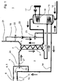
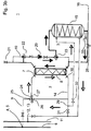
- FIG. 1 shows a first embodiment of a piping system 1 according to the invention, designed as a house piping system for drinking water heating, at the first, the basic features of such a piping system 1 are illustrated.
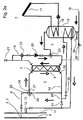
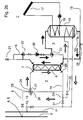
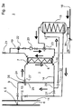
- the embodiments in the Figures 2 . 3 and 4 show comparable piping systems 1 according to the invention, each in details from the piping system 1 from FIG. 1 differ. The corresponding details will be discussed in due course. It goes without saying that the same reference numerals in the different exemplary embodiments stand for identical or comparable elements, so that repetitive statements relating to the respective exemplary embodiments are possible.
- a pipe system 1 comprises a first heat pipe system 2 and a second heat pipe system 3. Via a first end 4 of the first heat pipe system 2, a first heat transfer medium from a district heating network feed 6 is fed into the first heat pipe system 2 by means of a district heating network feed transfer station 5.
- the first heat transfer medium in this case is liquid water or water vapor at a temperature of for example 90 ° C in summer and 180 ° C in winter, for example.
- the arrows whose arrowheads are not filled and which are shown adjacent to the first heat pipe system 2 in the figures, each indicate the flow direction of the first heat transfer medium in the first heat pipe system. 2
- the first heat transfer medium flows in all three embodiments shown through a first pipe section and flows through a heat transfer medium inlet 7 on the primary side in a first heat exchanger 8 a.
- the first pipe section between the first end 4 of the heat pipe system 2 and the heat transfer medium inlet 7 is also referred to as the primary flow 9.
- the heat transfer medium flows through the first heat exchanger 8, in this case a shell-and-tube heat exchanger, by which heat stored in the first heat transfer medium can be transferred to a second heat transfer medium in the second heat pipe system 3.
- the second heat transfer medium contained in the second heat pipe system 3 is heated by the first heat exchanger 8.
- the second heat transfer medium is drinking water in the present example.
- the first heat transfer medium in the first heat pipe system 2 is cooled as it flows through the first heat exchanger 8, because part of its heat is released to the second heat transfer medium in the second heat pipe system 3.
- the first heat transfer medium leaves the first heat exchanger 8 through a heat transfer medium discharge opening 10 and then flows with a residual heat of about 50 ° C to 60 ° C in the direction of a district heating return 11, via a second end 12 of the first heat pipe system 2 and one on the second end arranged as a completion of the first heat pipe system 2 remote heating network return transfer station 13 is connected.
- the problem may in principle be that the first heat transfer medium in the pipe section between the heat transfer medium discharge opening 10 of the first heat exchanger 8 and the second end 12 of the first heat pipe system 2, which is also referred to as primary return 14, despite the heat transfer in the first heat exchanger 8 from the first heat pipe system 2 to the second Heat pipe system 3 still has a temperature which is well above a desired Fernellenetz Weglauftemperatur of about 35 C, for example, even at 50 ° C to 60 ° C.
- the second heat pipe system 3 has a heat transfer medium buffer storage as a reservoir for the second heat transfer medium.
- a much larger storage volume for heat is provided than in a simple conduit. Therefore, on the one hand, a large amount of the second heat transfer medium can be heated particularly well.
- the first heat transfer medium can be cooled more be to further reduce the return flow temperature of the first heat transfer medium in the district heating return 11.
- the residual heat removal takes place for preheating the second heat transfer medium as the last consumer heat removal from the first heat pipe system 2, before the first heat transfer medium reaches the second end 12 of the first heat pipe system 2.
- a second heat exchanger 15 is present in the heat pipe system 3. He provides the secondary side of the heat transfer medium buffer storage, as a cylindrical water tank. As can be seen, the water tank is widened in sections compared to its heat transfer medium inlet. The diameter of the water tank perpendicular to the flow direction is a multiple compared to the diameter of the heat transfer medium inlet.
- the heat transfer medium buffer storage is arranged in this case within the heat pipe system 3 immediately behind a heat transfer medium transfer point 16 of a heat transfer medium transfer station (not shown). This means a high temperature spread between the first heat transfer medium, which still has a temperature of between 50 ° C and 60 ° C in the primary return 14 behind the heat exchanger 8, and the second heat transfer medium, the network side usually provided with a temperature of about 10 ° C. becomes.
- the second heat transfer medium can be correspondingly preheated in the heat transfer medium buffer storage, which is the secondary side of the second heat exchanger 15, to a temperature of 20 ° C to 40 ° C.
- a solar thermal system 17 is present.
- the first heat pipe system 2, the second heat pipe system 3 and a pipe system of the solar thermal system 17 are fluid-separated.
- the solar thermal system 17 is connected to the second heat pipe system 3 thermally conductive.
- the solar thermal system 17 thus transfers heat directly to the second heat transfer medium within the heat transfer medium buffer of the second heat exchanger 15.
- the second heat transfer medium in the heat transfer medium buffer memory under common action of the residual heat preheating from the primary return 14 and the solar thermal even to temperatures of about 60 ° C are heated.
- the solar thermal system 17 is thermally coupled in a comparable manner to the second heat exchanger 15, as the pipe section of the first heat pipe system 2, which passes through the heat transfer medium buffer memory.
- a pipe segment 18 of the solar thermal system 17 passes through sections of the heat transfer medium storage tank and heats the second heat transfer medium there.
- this tube segment 18 of the solar thermal system 17 is arranged in a section of the heat transfer medium buffer storage, that is to say in this case in a section of the second heat exchanger 15, which, relative to the flow direction of the heat transfer medium, the first section in which the second Heat transfer medium is preheated via residual heat from the first heat pipe system 2, downstream.
- FIGS. 1 In the FIGS. 1 .
- exemplary embodiments are shown in which solar thermal energy and residual heat of the primary return 14 are transferred to the second heat transfer medium in each case in approximately one third of the heat transfer medium buffer storage tank through corresponding pipe segments.
- FIG. 3 If no solar thermal system 17 is provided. Instead, it's a pipe segment of the primary return 14 to almost the full length of the heat transfer medium buffer memory arranged in this. Thus, a particularly efficient heat removal from the primary return 14 and thus a greater cooling of the first heat transfer medium can be made possible.
- the second heat transfer medium flows preheated in a circulation circuit 19, and indeed whenever the second heat transfer medium is removed from the circulation circuit 19.
- the second heat transfer medium then passes through the first heat exchanger 8 to receive additional heat from the primary flow 9 of the first heat pipe system 2, ie primary heat, as needed.
- the first heat transfer medium and the second heat transfer medium in the region of the first heat exchanger 8 in the present embodiment flow in opposite directions to each other, whereby a good heat transfer can be ensured.
- a target temperature of the second heat transfer medium of about 55 ° C is desired.
- the additional primary heat transfer from the first heat exchanger 8 can be very low.
- the connected load of the heat pipe system 2 may possibly be adjusted downwards, so that the consumer can save costs.
- a circulation pump 20 in the circulation circuit 19 ensures that the second heat transfer medium is pumped in the circulation circuit 19 at a suitable speed in order to provide the target temperature constant.
- the consumer wishes to remove warm second heat transfer medium from the second heat pipe system 3, he can do so via, for example, a faucet 21.
- the warm second heat transfer medium is after opening the faucet 21 after a relatively short waiting time available.
- removed second heat transfer medium is replaced by second heat transfer medium from the heat transfer medium buffer storage, which is then in turn automatically filled with second heat transfer medium from the network.
- the circulation circuit 19 has a first legionella switching valve 22. It has proved expedient and sufficient second heat pipe systems 3, if they are designed as drinking water pipe systems, as in this case, once a day at 60 ° C. to flow through hot heat transfer medium in order to kill dangerous Legionella can.
- the first legionella switching valve 22 is arranged for this purpose so that the circulation circuit 19 can be flushed at the appropriate intervals with the suitably heated second heat transfer medium.
- the second heat transfer medium is heated so much by the shortened by switching the first Legionellenumschaltventils 22 flow path that the necessary increased water temperature can be easily reached.
- the second Legionellenumschaltventil 23 connects in the embodiments that in the FIGS. 1 and 4 are shown, the circulation circuit 19 with the secondary side heat transfer medium inlet of the second heat exchanger 15, so the heat transfer medium inlet of the heat transfer medium buffer memory.
- the second Legionellenumschaltventil 23 connects the circulation circuit 19 with the secondary side heat transfer medium outlet of the second heat exchanger 15, so the heat transfer medium outlet of the heat transfer medium buffer memory.
- the heat transfer medium storage tank can also be rinsed once a day with a second heat transfer medium heated to 60 ° C. in order to prevent a legionella contamination.
- the heat transfer medium is fed by activation, preferably time-controlled activation, of the second Legionellenumschaltventils 23 from the circulation circuit 19 in the Wärschenägermedium-buffer memory, so that the second heat exchanger 15 secondary side temporarily incorporated into the circulation circuit 19. If the second Legionellenumschaltventil 23 is actuated, the circulation pump 20 also works as a charge pump for the heat transfer medium buffer memory.
- the second heat transfer medium by operating the second Legionellenumschaltventils 23 via the heat transfer medium inlet on the secondary side in the heat transfer medium buffer memory be fed back.
- the second heat transfer medium is fed back into the heat transfer medium storage tank via the heat transfer medium discharge of the heat transfer medium buffer storage tank.
- the second Legionellenumschaltventil 23 fluidly connects in the embodiments of the Figures 2 and 3
- the second heat transfer medium in the heat transfer medium buffer to about 60 ° C or more are heated by operating the second Legionellenumschaltventils 23 and pressing the legionella protection flow valve 28, the second heat transfer medium according to the Figures 2 . 3 and 4 returned to the heat transfer medium storage tank via the heat transfer medium, brings there primary heat, which has already been taken from the first heat exchanger 8, and then flows, in the embodiments of the Figures 2 and 3 via the open legionella protection flow valve 28, in the circulation circuit 19 back.
- FIG. 4 An embodiment that can be particularly functional and inexpensive and therefore particularly recommendable is in FIG. 4 shown.
- the second Legionellenumschaltventil 23 connects in the form of a T-piece the circulation circuit 19 with the heat transfer medium inlet of the heat transfer medium buffer memory.
- the legionella protection flow valve 28 can be saved.
- the second Legionellenumschaltventil 23 is connected in normal operation so that the circulation circuit 19 is in operation and when removing second heat transfer medium from the faucet 21 automatically second heat transfer medium from the heat transfer medium buffer memory in the Circulation circuit 19 flows.
- Primary flow 9 and primary return 14 of the first heat pipe system 2 are in all embodiments fluidly connected in parallel to the first heat exchanger 8 via a jet pump 24. It can look like the example FIG. 1 the cooled first heat transfer medium with a temperature of for example 35 ° C from the primary return 14 of the first heat pipe system 2 with harnesserhitztem first heat transfer medium with a temperature of, for example, 90 ° C or 180 ° C from the primary flow 9 mix to the input side for the first heat exchanger 8 a suitable heat transfer medium temperature of, for example, 60 ° C to provide.
- the jet pump 24 comprises two inputs 25, 26 and an output 27.
- the first jet pump inlet 25 is fluidly connected to the primary flow 9, while the second jet pump inlet 26 is in fluid communication with the primary return 14, in FIG. 1 with a pipe section of the first heat pipe system 2, which is arranged behind the second heat exchanger 15 in this case.
- a T-connection 29 is a direct connection of the second jet pump inlet 26 with the heat transfer medium discharge opening 10 of the first heat exchanger 8, while the proportion of the first heat transfer medium, for heating the second heat transfer medium is used, is passed after flowing through the pipe section within the heat transfer medium buffer storage directly to the district heating return 11.
- the jet pump outlet 27 is connected to the heat carrier medium inflow opening 7 of the first heat exchanger 8 and provides there in each case a suitably mixed and thus suitably tempered first heat transfer medium.
- the second heat exchanger 15 so both the heat transfer medium buffer storage, as well as extending through the second heat exchanger 15 portion of the primary return 14, dry completely, if, for example, an exchange or a cleaning of the second heat exchanger 15 is required.
- a stop valve 30 On the secondary side, the inflow of the second heat transfer medium via a stop valve 30 can be prevented, so that the heat transfer medium buffer can be successively completely emptied.
- a first blockage valve 31 which is closed during normal operation of the first heat pipe system 2, can be opened so that the first heat transfer medium exiting from the first heat exchanger 8 via the heat carrier discharge opening 10 can continue to flow directly in the direction of the district heating return 11.
- a second blockage valve 32 which is open during normal operation of the pipeline system, closed, so that first heat transfer medium, which exits from the first heat exchanger 8 via the heat transfer outlet 10 no longer on the pipe section of the primary return 14, the second Heat transfer medium heated via the second heat exchanger, can continue to flow in the direction of the district heating return 11.
- the operation of the first heat pipe system 2 can in the embodiments of the Figures 2 . 3 and 4 So be maintained even if the second heat exchanger 15, for example, for maintenance reasons, must be removed from the second heat pipe system 3.
- the present invention can be achieved by providing a heat carrier buffer reservoir as a reservoir in a second heat pipe system 3 that the temperature spread of the primary flow 9, ie the pipe section of the first heat pipe system 2 between a first end 4 of the first heat pipe system 2 and a first heat exchanger 8, and the primary return 14, so the pipe section of the first heat pipe system 2 between the first heat exchanger 8 and the second end 12 of the first heat pipe system 2, can be significantly increased.
- the district heating supplier can refrain from cooling the district heating network return 11, for example via cooling towers or cooling basins, but also that the district heating consumer can achieve more effective district heat removal from the heat transfer medium made available to him.
- a piping system 1 improved in both economic and ecological terms, is provided with a first heat pipe system 2 and a second heat pipe system 3.
- the additional use of a solar thermal system 17 can be particularly advantageous in order to be able to preheat the second heat transfer medium even more strongly in the heat carrier buffer storage.
- a particular advantage in terms of health risks can be achieved if the heat carrier buffer storage already heated second heat transfer medium from a circulation circuit 19 can be supplied.
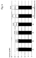
- FIG. 5 shows by way of example with which additionally available heating power is accompanied by a reduction of the district heating return temperature. For example, if the district heating return temperature is lowered from 65 ° C. to 40 ° C. by means of measures as described above for removing heat from the primary return, an increase of the heating power by, for example, 50% can be achieved.
Description
Die Erfindung betrifft ein Rohrleitungssystem gemäß des Oberbegriffs des Anspruchs 1 sowie ein Verfahren zum Erwärmen von Wärmeträgermedium in einem Wärmerohrsystem eines Rohrleitungssystems gemäß Anspruch 11.The invention relates to a pipeline system according to the preamble of
Der Fachmann kennt Rohrleitungssysteme, die ein erstes Wärmerohrsystem aufweisen, das Wärme aus dem Fernwärmenetz-Vorlauf bezieht und ein durch Wärmeentnahme abgekühltes Wärmeträgermedium in den Fernwärmenetz-Rücklauf des Fernwärmenetzes rückspeist. Außerdem ist Teil eines solchen Rohrleitungssystems ein zweites Wärmerohrsystem, das über einen Wärmetauscher Wärme aus dem ersten Wärmerohrsystem entnimmt, um damit ein zweites Wärmeträgermedium zu erwärmen. Dadurch kühlt sich das erste Wärmeträgermedium im ersten Wärmerohrsystem ab.The person skilled in the art knows of piping systems which have a first heat pipe system which draws heat from the district heating network supply and returns a heat transfer medium cooled by heat extraction into the district heating network return of the district heating network. In addition, part of such a piping system is a second heat pipe system, which removes heat from the first heat pipe system via a heat exchanger in order to heat a second heat transfer medium. As a result, the first heat transfer medium cools in the first heat pipe system.
Ein derartiges Rohrleitungssystem ist beispielsweise aus der
Ein anderes Rohrleitungssystem mit einer Vorerwärmung ist in der
Die
Aus der
Aus der
Die
Der Erfindung liegt die Aufgabe zugrunde, ein Rohrleitungssystem der oben beschriebenen Art, in der Wärme von einem ersten Wärmerohrsystem auf ein zweites Wärmerohrsystem übertragen wird, zu verbessern. Insbesondere soll die Effizienz der Wärmeentnahme gesteigert werden können, eine höhere Temperaturspreizung des Wärmeträgermediums zwischen Wärmevorlauf und Wärmerücklauf im ersten Wärmerohrsystem erreicht werden können, eine Verringerung der Verkalkung und eine verbesserte Wärmeträgermediumerwärmung für ein zweites Wärmerohrsystem ermöglicht werden. Zu diesem Zweck soll auch ein verbessertes Verfahren zum Erwärmen eines zweiten Wärmeträgermediums im zweiten Wärmerohrsystem bereitgestellt werden, um insbesondere zur Einhaltung der Vorschriften der Wärmelieferanten eine Temperatur des zweiten Wärmeträgermediums vor Rückspeisung in den Fernwärmenetz-Rücklauf von unter 45° C einhalten zu können.The invention has for its object to improve a piping system of the type described above in which heat is transferred from a first heat pipe system to a second heat pipe system. In particular, the efficiency of the heat removal should be increased, a higher temperature spread of the heat transfer medium between heat flow and heat return in the first heat pipe system can be achieved, a reduction of the calcification and improved heat transfer medium heating for a second heat pipe system allows. For this purpose, an improved method for heating a second heat transfer medium in the second heat pipe system should be provided in order to maintain a temperature of the second heat transfer medium before being fed back into the district heating network return of less than 45 ° C in particular to comply with the requirements of the heat suppliers.
Die Bezugszeichen in sämtlichen Ansprüchen haben keine einschränkende Wirkung, sondern sollen lediglich deren Lesbarkeit verbessern.The reference numbers in all claims have no limiting effect but are only intended to improve their readability.
Die der Erfindung zugrunde liegende Aufgabe wird erfindungsgemäß durch ein Rohrleitungssystem nach Anspruch 1 gelöst. Ferner wird sie durch ein Verfahren nach Anspruch 11 gelöst.The object underlying the invention is achieved by a piping system according to
Vorteilhafte Aus- und Weiterbildungen, welche einzeln oder in Kombination miteinander eingesetzt werden können, sind Gegenstand der abhängigen Ansprüche.Advantageous embodiments and developments, which can be used individually or in combination with each other, are the subject of the dependent claims.
Ein Wärmerohrsystem im Sinne der Erfindung ist ein Rohrsystem, das verwendet wird, um ein Wärmeträgermedium leiten zu können, so dass abhängig von der Temperatur eines damit in Wärmeübertragungsverbindung stehenden anderen Wärmerohrsystems Wärme zwischen den Wärmerohrsystemen ausgetauscht und entnommen werden kann.A heat pipe system in the sense of the invention is a pipe system which is used to be able to conduct a heat transfer medium, so that heat can be exchanged and removed between the heat pipe systems depending on the temperature of another heat pipe system connected thereto in heat transfer connection.
Ein Fernwärmenetz im Sinne der Erfindung ist ein von einem öffentlichen oder privaten Fernwärmeanbieter oder der öffentlichen Hand bereitgestelltes Rohrnetz, das Wärmekraftwerke mit den Wärmerohrsystemen von Verbrauchern verbindet. Ein Fernwärmenetz verfügt für gewöhnlich über einen Fernwärmenetz-Vorlauf mit erhitztem Wärmeträgermedium und einen Fernwärmenetz-Rücklauf mit dem gegenüber abgekühlten Wärmeträgermedium. Der Fernwärmenetz-Vorlauf beginnt in der Regel bei einem Heizkraftwerk oder Heizwerk, während der Fernwärmenetz-Rücklauf auch dort endet. Auf diese Weise wird ein Kreislauf bereitgestellt, in dem von einem Heizkraftwerk ein Wärmeträgermedium erhitzt wird, das Medium über den Fernwärmenetz-Vorlauf an Wärmerohrsysteme der Verbraucher bereitgestellt wird und anschließend das abgekühlte Wärmeträgermedium in den Fernwärmenetz-Rücklauf eingespeist wird, durch den es wieder zum Heizkraftwerk oder Heizwerk gelangt.A district heating network in the sense of the invention is a pipe network provided by a public or private district heating supplier or the public sector, which connects thermal power stations with the heat pipe systems of consumers. A district heating network usually has a district heating network feed with heated heat transfer medium and a district heating network return with the opposite cooled heat transfer medium. The district heating supply flow usually begins at a cogeneration plant or heating plant, while the district heating network return also ends there. In this way, a cycle is provided in which a heating medium from a heat transfer medium is heated, the medium is provided via the district heating network flow to heat pipe systems of consumers and then the cooled heat transfer medium is fed into the district heating network return through which it returns to the power plant or heating plant passes.
Im Sinne der Erfindung ist ein Wärmeträgermedium das Medium, das in dem Fernwärmenetz vorzugsweise mit einer Pumpe transportiert wird. Solch ein Wärmeträgermedium ist häufig heißes Wasser oder Wasserdampf, beispielsweise mit Temperaturen von 90 °C bis zu 180 °C. Im Falle von Wasserdampf als Wärmeträgermedium wird das Kondensat des abgekühlten Wasserdampfes in den Fernwärmenetz-Rücklauf rückgespeist.For the purposes of the invention, a heat transfer medium is the medium which is preferably transported in the district heating network with a pump. Such a heat transfer medium is often hot water or steam, for example at temperatures of 90 ° C to 180 ° C. In the case of steam as the heat transfer medium, the condensate of the cooled water vapor is fed back into the district heating network return.
Durch das erfindungsgemäße Rohrleitungssystem wird der Vorteil erreicht, dass ein gewisser Anteil Restwärme mit hoher Temperatur, der sonst in den Fernwärmenetz-Rücklauf des Fernwärmenetzes wieder eingespeist wird, zum Vorerwärmen von zweitem Wärmeträgermedium genutzt werden kann. Die Erfinder haben eine Lösung gefunden, mit der entgegen bestehender Vorurteile eine Wärmeträgermedium-Vorerwärmung großer Mengen eines Wärmeträgermediums stattfinden kann. Ein Wärmeträgermedium-Pufferspeicher wird bereitgestellt, um ein Reservoir für das zweite Wärmeträgermedium zu bilden, so dass gegenüber einer einfachen Rohrleitung mehr Volumen zum Zwischenspeichern des zweiten Wärmeträgermediums und somit auch zum Zwischenspeichern von Wärme zur Verfügung steht. So kann noch mehr vom Fernwärmenetz-Vorlauf bereitgestellte Wärme tatsächlich vom Verbraucher über den Primärrücklauf genutzt werden. Insbesondere kann in verbrauchsarmen Zeiten Wärmeenergie gespeichert werden, die in verbrauchsstarken Zeiten abgegeben werden kann. Zudem kann als Folge der Wärmezwischenspeicherung die Spreizung der Fernwärmenetz-Vorlauf- und der Fernwärmenetz-Rücklaufwärme weiter erhöht werden. Das kann wiederum darin resultieren, dass nur noch in verringertem Umfang vor einer erneuten Erhitzung des Wärmeträgermediums in einem Heizkraftwerk ein zusätzliches Abkühlen des Wärmeträgermediums, beispielsweise in Kühltürmen, erfolgen muss. Die Abgabe teurer Wärmeleistung in die Umwelt kann somit reduziert und CO2 eingespart werden. Die Anzahl von Kühltürmen kann insofern darüber hinaus beim Konzipieren und Konstruieren eines Fernwärmenetzes reduziert werden. Die Erfindung kann also einerseits positiv für den Umweltschutz sein und andererseits zugleich dem Verbraucher und dem Fernwärmeanbieter enorme Kostenvorteile und Leistungssteigerungen im Kraftwerk bringen.Through the piping system according to the invention the advantage is achieved that a certain proportion of residual heat at high temperature, which is otherwise fed back into the district heating network return of the district heating network, can be used for preheating of the second heat transfer medium. The inventors have found a solution with which, contrary to prevailing prejudices, a heat transfer medium preheating of large quantities of a heat transfer medium can take place. A heat transfer medium buffer storage is provided in order to form a reservoir for the second heat transfer medium, so that more volume is available for temporarily storing the second heat transfer medium and thus also for buffering heat compared to a simple pipeline. Thus even more heat provided by the district heating network feed can actually be used by the consumer via the primary return. In particular, heat energy can be stored in low-consumption times, which can be delivered in periods of high consumption. In addition, the spread of the district heating network supply and the district heating network return heat can be further increased as a result of heat storage. This, in turn, may result in an additional cooling of the heat carrier medium, for example in cooling towers, only to a lesser extent before renewed heating of the heat transfer medium in a cogeneration plant. The delivery of expensive heat output into the environment can thus be reduced and CO 2 can be saved. In addition, the number of cooling towers can be reduced in the design and construction of a district heating network. The invention can therefore be both positive for environmental protection and on the other hand at the same time bring the consumer and the district heating provider enormous cost advantages and performance gains in the power plant.
Bevorzugt ist der Wärmeträgermedium-Pufferspeicher verglichen mit seinem Wärmeträgermediumeinlauf, also einer Öffnung, durch die das zweite Wärmeträgermedium in den Wärmeträgermedium-Pufferspeicher eintritt, abschnittsweise aufgeweitet. Dadurch ist erreichbar, dass der Wärmeträgermedium-Pufferspeicher ein sehr großes Volumen des zweiten Wärmeträgermediums speichern kann. Das wiederum kann den Vorteil mit sich bringen, dass in dem Wärmeträgermedium-Pufferspeicher das zweite Wärmeträgermedium in großer Menge bereitgehalten werden kann, um in Zeiten geringen Wärmebedarfs eine große Menge Wärme aus dem Primärrücklauf des ersten Wärmerohrsystems oder auch einer anderen, zusätzlichen Wärmequelle aufzunehmen und in Zeiten erhöhten Bedarfs diese Wärme bereitstellen zu können. Durch den Wärmeträgermedium-Pufferspeicher kann eventuell also eine zusätzliche Wärmeentnahme aus dem Primärvorlauf nahezu unnötig oder zumindest verringert werden, wenn das zweite Wärmeträgermedium im Wärmeträgermedium-Pufferspeicher, also dem Reservoir, bereits eine ausreichend hohe Temperatur aufweist. Besonders vorzugsweise ist das zweite Wärmerohrsystem so eingerichtet, dass dem Wärmeträgermedium-Pufferspeicher nur dann zweites Wärmeträgermedium entnommen wird, wenn auch dem zweiten Wärmerohrsystem selbst das zweite Wärmeträgermedium entnommen wird. Solange keine Entnahme aus dem zweiten Wärmerohrsystem stattfindet, ruht also das zweite Wärmeträgermedium im Reservoir. Dadurch kann eine besonders gute Wärmeaufnahme und Wärmespeicherung möglich sein. In einer besonders bevorzugten Ausführungsform ist der Wärmeträgermedium-Pufferspeicher im Wesentlichen kreiszylindrisch ausgeführt.Preferably, the heat transfer medium storage tank is compared with its heat transfer medium inlet, so an opening through which the second heat transfer medium enters the heat transfer medium buffer, sections widened. As a result, it can be achieved that the heat transfer medium buffer storage can store a very large volume of the second heat transfer medium. This in turn can bring the advantage that in the heat transfer medium buffer the second heat transfer medium can be kept in large quantities to absorb a large amount of heat from the primary return of the first heat pipe system or other additional heat source in times of low heat demand and in Times of increased need to provide this heat. By the heat transfer medium buffer memory may therefore be an additional heat extraction from the primary flow almost unnecessary or at least reduced if the second heat transfer medium in the heat transfer medium buffer storage, ie the reservoir, already has a sufficiently high temperature. Particularly preferably, the second heat pipe system is set up so that only the second heat transfer medium is removed from the heat transfer medium buffer storage, even if the second heat transfer medium itself is taken from the second heat transfer medium. As long as no removal takes place from the second heat pipe system, so the second heat transfer medium rests in the reservoir. As a result, a particularly good heat absorption and heat storage can be possible. In a particularly preferred embodiment, the heat transfer medium buffer storage is designed substantially circular cylindrical.
Vorzugsweise ist der Wärmeträgermediumeinlauf des Wärmeträgermedium-Pufferspeichers im Vergleich zu einem Innendurchmesser des Wärmeträgermedium-Pufferspeichers jeweils senkrecht zur Durchströmrichtung des zweiten Wärmeträgermediums sehr viel kleiner. Nochmals bevorzugt ist der Innendurchmesser des Wärmeträgermedium-Pufferspeichers senkrecht zur Durchströmrichtung des zweiten Wärmeträgermediums mindestens 1,5 mal so groß, besonders vorzugsweise jedoch mindestens doppelt so groß, mindestens dreimal so groß, mindestens achtmal so groß, mindestens fünfzehn mal so groß, mindestens zwanzigmal so groß oder auch mindestens fünfzigmal so groß wie der Durchmesser seines Wärmeträgermediumeinlaufs. Dadurch kann im Vergleich mit einem normalen Rohrstück, das keine mindestens abschnittsweise Aufweitung aufweist, ein besonders großes Reservoir für das zweite Wärmeträgermedium bereitgestellt werden. Ganz besonders vorzugsweise ist der Innendurchmesser der Durchmesser eines kreiszylindrischen Wärmeträgermedium-Pufferspeichers. Vorzugsweise ist dies also die Strecke, die geradlinig von einem Punkt der Zylindermantelfläche durch die Mittelachse des Zylinders zu einem gegenüberliegenden Punkt auf der Zylindermantelfläche führt, wobei die Strecke senkrecht zur Mittelachse verläuft. Bevorzugt ist, dass der Wärmeträgermediumeinlauf als Rohranschluss ausgeführt ist.Preferably, the heat transfer medium inlet of the heat transfer medium buffer storage is in comparison to an inner diameter of the heat transfer medium buffer storage each perpendicular to the flow direction of the second heat transfer medium much smaller. Again, preferably, the inner diameter of the heat transfer medium storage tank is at least 1.5 times, particularly preferably at least twice as large, at least three times as large, at least eight times as large, at least fifteen times as large, at least twenty times so perpendicular to the flow direction of the second heat transfer medium large or at least fifty times as large as the diameter of its heat transfer medium inlet. As a result, a particularly large reservoir for the second heat transfer medium can be provided in comparison with a normal pipe section, which does not have at least sections widening. Most preferably, the inner diameter of the diameter of a circular cylindrical heat transfer medium buffer memory. Preferably, this is the route that is straight from a point of Cylinder surface through the central axis of the cylinder leads to an opposite point on the cylinder surface, the distance is perpendicular to the central axis. It is preferred that the heat transfer medium inlet is designed as a pipe connection.
Ein bevorzugter Wärmeträgermedium-Pufferspeicher ist ein Wärmeträgermedium-Tank. Ist das Wärmeträgermedium Wasser, insbesondere Trinkwasser, so ist der Wärmeträgermedium-Pufferspeicher besonders vorzugsweise ein Wassertank. Derartige Tanks als Reservoirs sind vorzugsweise leicht zu beschaffen, preisgünstig, wartungsarm und in großer Auswahl auf dem Markt vorhanden. Zudem stellen sie vorzugsweise ein großes Speichervolumen bereit, besonders vorzugsweise ein Volumen zum Zwischenspeichern des zweiten Wärmeträgermediums von mehr als 100 Litern, mehr als 200 Litern, mehr als 400 Litern, mehr als 750 Litern oder auch mehr als oder viel mehr als 1000 Litern. Ganz besonders ist für einen Wärmeträgermedium-Tank bei einem Bedarf für das zweite Wärmeträgermedium von 600 Litern pro Tag ein Speichervolumen von 300 Litern bevorzugt. Entsprechend liegt ein besonders bevorzugtes Fassungsvermögen für den Wärmeträgermedium-Tank beim doppelten Tagesbedarf an zweitem Wärmeträgermedium. So kann eine ausreichend große Menge Wärmeträgermedium zwischengespeichert werden, ohne übermäßig Raum für das Reservoir zu beanspruchen. Der Wärmeträgermedium-Tank kann aus Edelstahl gefertigt sein. Er kann zudem oder alternativ thermoglasiert, verzinkt oder kunststoffbeschichtet sein. Vorzugsweise hat er eine zylindrische, besonders bevorzugt eine kreiszylindrische Form. Ganz besonders bevorzugt liegen sich der Wärmeträgermediumeinlauf und ein Wärmeträgermediumablauf des Wärmeträgermedium-Pufferspeichers genau gegenüber. So kann ein besonders günstiger Strömungsverlauf und eine besonders günstige Wärmeabgabe für das zweite Wärmeträgermedium erreicht werden. Ein bevorzugter Wärmeträgermedium-Pufferspeicher hat zudem eine Wärmeisolierung, vorzugsweise auf seiner Außenseite. Besonders bevorzugt ist, dass eine Wärmeisolierung auf die Außenseite als Hartschaum aufgeschäumt ist. Solch eine Wärmeisolierung kann sehr effektiv eine unerwünschte Wärmeabgabe von dem zweiten Wärmeträgermedium im Wrämeträgermedium-Pufferspeicher durch die Wand des Wärmeträgermedium-Pufferspeicher vermindern, so dass vorteilhafterweise keine nennenswerte Wärmemenge als abgestrahlte Wärme verloren geht.A preferred heat transfer medium buffer storage is a heat transfer medium tank. If the heat transfer medium is water, in particular drinking water, then the heat transfer medium storage tank is particularly preferably a water tank. Such tanks as reservoirs are preferably easy to obtain, inexpensive, low-maintenance and available in large selection on the market. In addition, they preferably provide a large storage volume, more preferably a volume for temporarily storing the second heat transfer medium of more than 100 liters, more than 200 liters, more than 400 liters, more than 750 liters or more than or much more than 1000 liters. Especially for a heat transfer medium tank with a need for the second heat transfer medium of 600 liters per day, a storage volume of 300 liters is preferred. Accordingly, a particularly preferred capacity for the heat transfer medium tank is twice the daily requirement for the second heat transfer medium. Thus, a sufficiently large amount of heat transfer medium can be cached without taking up too much space for the reservoir. The heat transfer medium tank can be made of stainless steel. It can also or alternatively thermo-glazed, galvanized or plastic coated. Preferably, it has a cylindrical, more preferably a circular cylindrical shape. Most preferably, the heat transfer medium inlet and a heat transfer medium outlet of the heat transfer medium buffer storage are exactly opposite. Thus, a particularly favorable flow profile and a particularly favorable heat output for the second heat transfer medium can be achieved. A preferred heat transfer medium storage tank also has a thermal insulation, preferably on its outside. It is particularly preferred that a heat insulation is foamed onto the outside as rigid foam. Such a thermal insulation can very effectively reduce unwanted heat release from the second heat transfer medium in the heat transfer medium storage tank through the wall of the heat transfer medium storage tank, so that advantageously no significant amount of heat is lost as radiated heat.
In einer bevorzugten Ausführungsform verläuft der Rohrleitungsabschnitt, der den ersten Wärmetauscher mit dem zweiten Ende des ersten Wärmerohrsystems fluidverbindet, durch den Wärmeträgermedium-Pufferspeicher hindurch, um das zweite Wärmeträgermedium zu erwärmen. So kann es ermöglicht werden, auf komplizierte zusätzliche Schaltungen und/oder Zuleitungen zu verzichten. Der besagte Rohrleitungsabschnitt, auch Primärrücklauf genannt, wird also so geführt, dass der Wärmeträgermedium-Pufferspeicher mit Restwärme direkt, beispielsweise über ein Heizbündel, erhitzt werden kann. Er kann alternativ oder zusätzlich auch schraubenförmig um den Wärmeträgermedium-Pufferspeicher gewickelt sein. Besonders bevorzugt ist jedoch, dass der Primärrücklauf, also der Rohrleitungsabschnitt zwischen erstem Wärmetauscher und zweitem Ende des ersten Wärmerohrsystems, abschnittsweise in den Wärmeträgermedium-Pufferspeicher hineinreicht. Dort verläuft er vorzugsweise in der Art eines Tauchsieders oder eines bekannten Heizbündels spiralförmig. Bevorzugt ist, dass der Primärrücklauf nur an oder in einem gewissen Abschnitt des Wärmeträgermedium-Pufferspeicher angeordnet ist. Besonders bevorzugt ist, dass er nur an oder in 10%, 20%, 30% 40% oder nochmals besonders bevorzugt 50% des Wärmeträgermedium-Pufferspeichers angeordnet ist. Alternativ kann er aber auch außen oder innen entlang an bis zu 100% des Wärmeträgermedium-Pufferspeichers angeordnet sein, bezogen auf die Länge des Wärmeträgermedium-Pufferspeichers. So kann ein besonders großer Abschnitt des Primärrücklaufs Wärme an das zweite Wärmeträgermedium im Wärmeträgermedium-Pufferspeicher übertragen. Schließlich tritt der Primärrücklauf vorzugsweise aus dem Wärmeträgermedium-Pufferspeicher dann mit Ziel zweites Ende des ersten Wärmerohrsystems wieder aus. Besonders bevorzugt ist, dass er benachbart zum Wärmeträgermediumeinlauf aus dem Wärmeträgermedium-Pufferspeicher austritt, während er ungefähr bei vorzugsweise der halben Füllhöhe oder der vollen Füllhöhe des Wärmeträgermedium-Pufferspeichers in den Wärmeträgermedium-Pufferspeicher eintritt, so dass er vorzugsweise entlang 50% der Länge des Pufferspeichers angeordnet ist.In a preferred embodiment, the pipe section, which fluidly connects the first heat exchanger to the second end of the first heat pipe system, passes through the heat transfer medium storage tank to heat the second heat transfer medium. Thus, it may be possible to dispense with complicated additional circuits and / or leads. Said pipe section, also called primary return, is thus performed so that the heat transfer medium buffer storage with residual heat directly, for example via a heating coil, can be heated. It may alternatively or additionally be helically wound around the heat transfer medium buffer storage. However, it is particularly preferred that the primary return, ie the pipe section between the first heat exchanger and the second end of the first heat pipe system, extends in sections into the heat transfer medium buffer memory. There it runs preferably in the manner of an immersion heater or a known Heizbündels spiral. It is preferred that the primary return is arranged only on or in a certain portion of the heat transfer medium buffer memory. It is particularly preferred that it is arranged only on or in 10%, 20%, 30% 40% or even more preferably 50% of the heat transfer medium buffer storage. Alternatively, however, it can also be arranged outside or inside along up to 100% of the heat transfer medium buffer storage, based on the length of the heat transfer medium buffer storage. Thus, a particularly large portion of the primary return heat transferred to the second heat transfer medium in the heat transfer medium buffer memory. Finally, the primary return preferably exits from the heat transfer medium storage tank then ends second end of the first heat pipe system again. It is particularly preferred that it exits adjacent to the heat transfer medium inlet from the heat transfer medium buffer storage, while it enters the heat transfer medium buffer memory at approximately half the filling level or the full filling height of the heat transfer medium buffer storage, so that it preferably along 50% of the length of the buffer memory is arranged.
Beim Austreten aus dem ersten Wärmetauscher hat das erste Wärmeträgermedium zwischen erstem Wärmetauscher und Wärmeträgermedium-Pufferspeicher noch eine primäre Restwärme von vorzugsweise ca. 50 °C bis 60°C und in dem Rohrsegment des ersten Wärmerohrsystems, das dem Rohrsegment, das den Wärmeträgermedium-Pufferspeicher erwärmt, in Strömungsrichtung nachgelagert ist, noch eine verbleibende Restwärme von vorzugsweise 35 °C oder weniger. So ist es möglich, das zweite Wärmeträgermedium im Wärmeträgermedium-Pufferspeicher von etwa 10 °C, was im Wesentlichen der Temperatur in einem Wärmeträgermediumnetz des zweiten Wärmeträgermediums entsprechen kann, aus dem das zweite Wärmeträgermedium entnommen wird, und was im Wesentlichen der typischen Temperatur von Trinkkaltwasser entspricht, auf etwa 20 °C bis 40 °C zu erwärmen. Entsprechend muss das zweite Wärmeträgermedium durch den ersten Wärmetauscher anschließend nur noch um etwa 20 bis 40 K erwärmt werden, um eine Zieltemperatur von etwa 60 °C, beispielsweise an einer Entnahmestelle bei Trinkwassererwärmern, zu erreichen. Es muss also durch den ersten Wärmetauscher wesentlich weniger Wärme aus dem Primärvorlauf entnommen werden. Eine energieeffiziente Wärmeentnahme ist somit erreichbar.Upon exiting the first heat exchanger, the first heat transfer medium between the first heat exchanger and heat transfer medium buffer memory still has a primary residual heat of preferably about 50 ° C to 60 ° C and in the pipe segment of the first heat pipe system, which heats the pipe segment, which heats the heat transfer medium buffer , is downstream, in the flow direction, still a remaining Residual heat of preferably 35 ° C or less. Thus, it is possible, the second heat transfer medium in the heat transfer medium buffer storage of about 10 ° C, which may correspond substantially to the temperature in a heat transfer medium network of the second heat transfer medium, from which the second heat transfer medium is removed, and which corresponds substantially to the typical temperature of drinking cold water to warm to about 20 ° C to 40 ° C. Accordingly, the second heat transfer medium must then be heated by the first heat exchanger only by about 20 to 40 K in order to achieve a target temperature of about 60 ° C, for example, at a withdrawal point in drinking water heaters. It must therefore be removed from the primary flow through the first heat exchanger much less heat. An energy-efficient heat extraction is thus achievable.
Bevorzugt ist, dass der zweite Wärmetauscher sekundärseitig als Wärmeträgermedium-Pufferspeicher ausgeführt ist. So kann auf einfache Weise ein Wärmeübertragungsmittel mit einem Reservoir für das zweite Wärmeträgermedium in einer einzigen Baueinheit bereitgestellt werden, was sich vorteilhaft auf die Erstellungskosten auswirken kann. Alternativ kann aber der Wärmetauscher auch über eine Wärmeverbindung mit einem separaten Wärmeträgermedium-Pufferspeicher verbunden sein. Das kann die Flexibilität und/oder die Betriebssicherheit hinsichtlich der Anordnung erhöhen, indem beispielsweise die Wärme vom zweiten Wärmetauscher über wärmeleitfähige Materialien an ein separates Reservoir weitergeleitet wird. Besonders vorzugsweise ist der zweite Wärmetauscher jedoch sekundärseitig als Wärmeträgermedium-Tank, vorzugsweise mit bereits beschriebener besonderer Wärmeisolierung, ausgeführt, um eine besonders kompakte Bauform zu ermöglichen.It is preferred that the second heat exchanger is designed on the secondary side as a heat transfer medium buffer memory. Thus, in a simple manner, a heat transfer medium can be provided with a reservoir for the second heat transfer medium in a single structural unit, which can have an advantageous effect on the production costs. Alternatively, however, the heat exchanger can also be connected via a heat connection to a separate heat transfer medium buffer storage. This can increase the flexibility and / or the operational reliability with respect to the arrangement, for example by the heat from the second heat exchanger via thermally conductive materials is forwarded to a separate reservoir. Particularly preferably, however, the second heat exchanger is on the secondary side as a heat transfer medium tank, preferably with already described special heat insulation, designed to allow a particularly compact design.
In einer bevorzugten Ausführungsform umfasst das zweite Wärmerohrsystem einen Zirkulationskreislauf. Es ist erwünscht, dass beispielsweise Warmwasser als zweites Wärmeträgermedium bereits in kurzer Zeit nach dem Öffnen einer Wasserentnahmeeinrichtung, beispielsweise eines Wasserhahns, zur Verfügung steht. Dies kann vorteilhafterweise durch einen Zirkulationskreislauf erreicht werden. Vorzugsweise wird in dem Zirkulationskreislauf durch eine Zirkulationspumpe das zweite Wärmeträgermedium in ständigem Fluß durch den ersten Wärmetauscher geleitet, sodass das gesamte im Zirkulationskreislauf vorhandene Wärmeträgermedium eine im Wesentlichen konstant hohe Temperatur aufweist. Sie liegt vorzugsweise bei 55 °C, kann aber unter anderem auch bei 60 °C liegen oder bei 50 °C. Entsprechend liegt die Temperatur für gewöhnlich vorzugsweise in einem Intervall zwischen 50 °C und 60 °C. Auch davon abweichende Temperaturen sind möglich. Der Zirkulationskreislauf wird mit zweitem Wärmeträgermedium aus dem Wärmeträgermedium-Pufferspeicher nachgefüllt, sobald eine Wärmeträgermediumentnahme aus dem Zirkulationskreislauf stattfindet. Dann strömt ebenfalls automatisch zweites Wärmeträgermedium aus dem Netz in den Wärmeträgermedium-Pufferspeicher nach. Alternativ kann das zweite Wärmerohrsystem aber auch ohne einen Zirkulationskreislauf ausgeführt sein. Das kann eine kostengünstige Lösung sein, wenn eine längere Vorlaufzeit hinnehmbar ist, bevor nach dem Öffnen der Wasserentnahmeeinrichtung warmes Wärmeträgermedium zur Verfügung stehen soll. Dann wird das Wärmeträgermedium vorzugsweise über ein einfaches Rohrsegment aus dem Wärmeträgermedium-Pufferspeicher bezogen, das Rohrsegment am ersten Wärmetauscher vorbeigeführt, dabei das Wärmeträgermedium erhitzt und anschließend aus der Wasserentnahmeeinrichtung entnommen, und zwar immer in dem Moment, wenn die Wasserentnahmeeinrichtung zur Wasserentnahme geöffnet wird. Bevorzugt ist, dass das zweite Wärmeträgermedium, wenn es den ersten Wärmetauscher passiert, entgegensetzt zur Strömungsrichtung des ersten Wärmeträgermediums fließt. So kann eine sehr günstige Wärmeübertragung gewährleistet sein. Alternativ können die Strömungsrichtungen aber auch gleichgerichtet sein, beispielsweise, wenn die Netzanschlusssituation es erfordert.In a preferred embodiment, the second heat pipe system comprises a circulation circuit. It is desirable that, for example, hot water as the second heat transfer medium is already available in a short time after opening a water extraction device, for example a faucet. This can advantageously be achieved by a circulation circuit. Preferably, in the circulation circuit by a circulation pump, the second heat transfer medium is passed in constant flow through the first heat exchanger, so that the entire present in the circulation heat transfer medium has a substantially constant high temperature. It is preferably 55 ° C, can but also at 60 ° C or at 50 ° C. Accordingly, the temperature is usually preferably in an interval between 50 ° C and 60 ° C. Also deviating temperatures are possible. The circulation circuit is refilled with a second heat transfer medium from the heat transfer medium buffer storage as soon as a heat transfer medium removal takes place from the circulation circuit. Then also second heat transfer medium flows automatically from the network into the heat transfer medium buffer storage. Alternatively, however, the second heat pipe system can also be designed without a circulation circuit. This can be a cost effective solution if a longer lead time is acceptable before warm water carrier medium is to be available after opening the water extractor. Then, the heat transfer medium is preferably obtained via a simple pipe segment from the heat transfer medium buffer storage, the pipe segment passed on the first heat exchanger, while the heat transfer medium heated and then removed from the water extraction device, and always at the moment when the water extraction device is opened to remove water. It is preferred that the second heat transfer medium, when it passes the first heat exchanger, opposite to the flow direction of the first heat transfer medium flows. So a very favorable heat transfer can be guaranteed. Alternatively, however, the flow directions can also be rectified, for example when the grid connection situation requires it.
Im Zirkulationskreislauf ist vorzugsweise ein Legionellen-Umschaltventil angeordnet. Dadurch kann einmal täglich ein Erhitzen des Wärmeträgermediums auf bis zu 60 °C oder auch mehr erfolgen, um Legionellen und andere Keime wirksam abtöten zu können. Vorzugsweise ist es in Reihe mit der Zirkulationspumpe geschaltet. Es erlaubt vorzugsweise, die Umlaufzeit des zweiten Wärmeträgermediums durch eine Wegstreckenverkürzung zu verringern, so dass eine höhere Temperatur des zweiten Wärmeträgermediums erreicht werden kann.In the circulation circuit, a legionella changeover valve is preferably arranged. As a result, once a day, a heating of the heat transfer medium to up to 60 ° C or more done to effectively kill Legionella and other germs can. Preferably, it is connected in series with the circulation pump. It preferably allows the circulation time of the second heat transfer medium to be reduced by shortening the distance, so that a higher temperature of the second heat transfer medium can be achieved.
Vorzugsweise ist eine Fluidverbindung vorhanden, über die das zweite Wärmeträgermedium erneut in den Wärmeträgermedium-Pufferspeicher eingespeist werden kann, nachdem es bereits durch den ersten Wärmetauscher und den zweiten Wärmetauscher erwärmt worden ist. Bevorzugt ist in dieser Hinsicht, dass das zweite Wärmerohrsystem einen Zirkulationskreislauf umfasst, der mit dem Wärmeträgermedium-Pufferspeicher fluidverbunden ist, um das zweite Wärmeträgermedium aus dem Zirkulationskreislauf in den Wärmeträgermedium-Pufferspeicher einleiten zu können. Die Idee ist also, insbesondere temporär eine zusätzliche Erwärmung des zweiten Wärmeträgermediums innerhalb des Wärmeträgermedium-Pufferspeichers erreichen zu können. Die Fluidverbindung wird aus diesem Grund vorzugsweise über ein Ventil hergestellt. So kann beispielsweise das zweite Wärmeträgermedium aus dem Zirkulationskreislauf in dem oder die Wärmeträgermedium-Pufferspeicher eingeleitet werden, den Wärmeträgermedium-Pufferspeicher durchströmen und anschließend wieder in den Zirkulationskreislauf einströmen. Das Ventil dient also vorzugsweise als ein Legionellen-Umschaltventil, besonders vorzugsweise als ein zweites Legionellen-Umschaltventil, das zusätzlich zu dem ersten Legionellen-Umschaltventil bereitgestellt wird. Eine Zirkulationspumpe kann vorzugsweise bei entsprechender Ventilstellung als Ladepumpe für den Wärmeträgermedium-Pufferspeicher dienen. Alternativ kann eine gesonderte Ladepumpe vorhanden sein. Auf die beschriebene Weise kann eine Legionellen-Abtötung für den oder die Wärmeträgermedium-Pufferspeicher bereitgestellt werden. Dadurch kann der Benutzer vor Legionellen oder anderen Krankheitserregern besser geschützt sein.Preferably, a fluid connection is provided, via which the second heat transfer medium can be fed again into the heat transfer medium buffer storage, after it has already been heated by the first heat exchanger and the second heat exchanger. In this regard, it is preferred that the second heat pipe system comprises a circulation circuit that communicates with the heat transfer medium buffer tank is fluid-connected to initiate the second heat transfer medium from the circulation circuit in the heat transfer medium buffer memory can. The idea is therefore to be able to achieve, in particular temporarily, additional heating of the second heat transfer medium within the heat transfer medium buffer storage. For this reason, the fluid connection is preferably made via a valve. Thus, for example, the second heat transfer medium from the circulation circuit in the or the heat transfer medium buffer storage are introduced, flow through the heat transfer medium buffer storage and then flow back into the circulation circuit. Thus, the valve preferably serves as a legionella switching valve, more preferably as a second legionella switching valve provided in addition to the first legionella switching valve. A circulation pump can preferably serve as a charge pump for the heat transfer medium storage tank with appropriate valve position. Alternatively, a separate charge pump may be present. In the manner described, a Legionella killing for the or the heat transfer medium buffer memory can be provided. This allows the user to be better protected from Legionella or other pathogens.
Bevorzugt ist, dass das vorangehend beschriebene Einspeisen des bereits durch den ersten und den zweiten Wärmetauscher erwärmten zweiten Wärmeträgermediums über den Wärmeträgermediumeinlauf des Wärmeträgermedium-Pufferspeichers erfolgt, vorzugsweise über das vorangehend beschriebene Ventil. Besonders bevorzugt ist, dass das zweite Legionellen-Umschaltventil den Zirkulationskreislauf mit dem Wärmeträgermediumeinlauf des Wärmeträgermedium-Pufferspeichers verbindet. So kann ein zweites Wärmeträgermedium, beispielsweise 60 °C heißes Wasser, aus dem Zirkulationskreislauf in den Pufferspeicher geleitet, bevorzugt gepumpt, werden, um dort eventuell vorhandene Legionellen oder andere Keime abtöten zu können. Das Wasser fließt danach zurück in den Zirkulationskreislauf. Der Wärmeträgermedium-Pufferspeicher wird in einer Spülstellung des Ventils also Teil des Zirkulationskreislaufs, sofern ein Zirkulationskreislauf vorhanden ist. Empfohlen ist, einmal täglich für 30 Minuten den Wärmeträgermedium-Pufferspeicher mit mindestens 60 °C heißem zweitem Wärmeträgermedium aus dem Zirkulationskreislauf zu spülen. Führt man das zweite Wärmeträgermedium aus dem Zirkulationskreislauf über den Wärmeträgermediumeinlauf dem Wärmeträgemedium-Pufferspeicher zu, kann auf zusätzliche Leitungssegmente oder Anschlussöffnungen verzichtet werden, was sich kostensenkend auf diese Ausführungsform des Rohrleitungssystems auswirken kann. Eine separate Zuleitung zusätzlich zum Wärmeträgermediumeinlauf und zum Wärmeträgermediumablauf ist alternativ auch möglich. Zu beachten ist, dass der Zirkulationskreislauf fakultativ ist und die Beimischung von bereits durch den ersten und den zweiten Wärmetauscher erhitzten zweiten Wärmeträgermedium auch aus einem einfachen Rohrstück erfolgen kann, falls ein Zirkulationskreislauf nicht vorhanden ist. In diesem Fall kann das einfache Rohrstück beispielsweise durch eine Elektrobegleitheizung erwärmt werden, um so eine Erhitzung des zweiten Wärmeträgermediums in diesem Rohrstück zu ermöglichen. Eine bevorzugte Elektrobegleitheizung ist schraubenförmig um das Rohrstück gewickelt, besonders bevorzugt auf einer Länge, die größer ist als die Hälfte der Länge des Rohrstücks.It is preferred that the previously described feeding of the second heat transfer medium already heated by the first and the second heat exchanger takes place via the heat transfer medium inlet of the heat transfer medium buffer storage, preferably via the previously described valve. It is particularly preferred that the second legionella switching valve connects the circulation circuit with the heat transfer medium inlet of the heat transfer medium buffer memory. Thus, a second heat transfer medium, for example, 60 ° C hot water, passed from the circulation circuit in the buffer memory, preferably pumped to be able to kill there any existing Legionella or other germs can. The water then flows back into the circulation circuit. The heat transfer medium buffer memory is in a flushing position of the valve so part of the circulation circuit, if a circulation circuit is present. It is recommended to rinse the heat transfer medium storage tank once a day for 30 minutes with at least 60 ° C second heat transfer medium from the circulation circuit. Leads to the second heat transfer medium from the circulation circuit via the heat transfer medium inlet to the heat transfer medium buffer storage, can on additional line segments or Connection openings are dispensed with, which can have a cost-reducing effect on this embodiment of the piping system. A separate supply line in addition to the heat transfer medium inlet and the heat transfer medium drain is alternatively also possible. It should be noted that the circulation circuit is optional and the admixture of already heated by the first and the second heat exchanger second heat transfer medium can also be made of a simple piece of pipe, if a circulation circuit is not present. In this case, the simple pipe section can be heated, for example, by an electric trace heating, so as to allow heating of the second heat transfer medium in this pipe section. A preferred Elektrobegleitheizung is helically wound around the pipe section, more preferably on a length which is greater than half the length of the pipe section.
In einer anderen Ausführungsform ist bevorzugt, dass das zweite Wärmeträgermedium aus dem Zirkulationskreislauf über den Wärmeträgermediumablauf des Wärmeträgermedium-Pufferspeichers dem Wärmeträgermedium-Pufferspeicher zugeführt werden kann, um die entkeimende Wirkung zu erreichen. Vorzugsweise kann ein zweites Legionellenumschaltventil in dem Zirkulationskreislauf für diesen Zweck so gestaltet werden, dass der Wärmeträgermedium-Pufferspeicher temporär derart in den Zirkulationskreislauf eingeschlossen werden kann, dass er entgegen der üblichen Flussrichtung befüllt wird, also von dem Wärmeträgermediumablauf zum Wärmeträgermediumeinlauf hin. Dann ist weiterhin bevorzugt, dass eine Flussverbindung zwischen Zirkulationskreislauf und Wärmeträgermediumeinlauf des Wärmeträgermedium-Pufferspeichers, also an einem Punkt zwischen Wärmeträgermedium-Pufferspeicher und Wärmeträgermediumübergabepunkt des zweiten Wärmeträgermediums, eingerichtet wird, die vorzugsweise durch ein zusätzliches Legionellenschutz-Durchflussventil temporär verschlossen werden kann. So kann das zweite Wärmeträgermedium aus dem Zirkulationskreislauf in den Wärmeträgermedium-Pufferspeicher entgegen der üblichen Flussrichtung rückgespeist und darin aufgestaut werden. Eine besonders preisgünstige und funktionale und deshalb besonders bevorzugte Lösung kann bereitgestellt werden, wenn die Verbindung zwischen Wärmeträgermediumeinlauf des Wärmeträgermedium-Pufferspeichers und des Zirkulationskreislaufs als T-Abzweig im Zirkulationskreislauf realisiert ist. Vorzugsweise ist der T-Abzweig mit einem, bevorzugt dem zweiten, Legionellenumschaltventil versehen. Auf ein Legionellenumschaltventil auf der Fluidverbindung zwischen Wärmeträgermediumablauf und Zirkulationskreislauf und auf das Legionellenschutz-Durchflussventil kann dann verzichtet werden. So kann mit nur einem einzigen Ventil ein Legionellenschutz für den Wärmeträgermedium-Pufferspeicher realisiert werden, das ein Rückführen von zweitem Wärmeträgermedium über den Wärmeträgermediumablauf ermöglicht. Diese voranstehend beschriebenen Schaltungen erlauben ebenfalls eine ausreichende Erwärmung des gesamten zweiten Wärmeträgermediums im Wärmeträgermedium-Pufferspeicher auf über 60 °C, um Keime abzutöten, auch wenn in diesem Fall die Einströmrichtung in den Wärmeträgermedium-Pufferspeicher temporär umgekehrt wird. Ein Rückströmen von zweitem Wärmeträgermedium in das Wärmeträgermediumnetz über den Wärmeträgermediumübergabepunkt hinaus ist nicht zu befürchten, da in diesem Bereich vom Fachmann ein Rückschlagventil vorgesehen ist, das ausschließlich den Fluss von zweitem Wärmeträgermedium in Richtung Entnahmestelle zulässt.In another embodiment, it is preferred that the second heat transfer medium from the circulation circuit via the heat transfer medium outlet of the heat transfer medium buffer storage can be supplied to the heat transfer medium buffer memory to achieve the sterilizing effect. Preferably, a second Legionellenumschaltventil be designed in the circulation circuit for this purpose so that the heat transfer medium buffer memory can be temporarily included in the circulation so that it is filled against the usual flow direction, ie from the heat transfer medium outlet to the heat transfer medium inlet. Then it is further preferred that a flow connection between the circulation circuit and heat transfer medium inlet of the heat transfer medium buffer storage, ie at a point between the heat transfer medium buffer storage and heat transfer medium transfer point of the second heat transfer medium, is set, which can be preferably temporarily closed by an additional legionella protection flow valve. Thus, the second heat transfer medium can be fed back from the circulation circuit in the heat transfer medium storage tank contrary to the usual flow direction and dammed therein. A particularly inexpensive and functional and therefore particularly preferred solution can be provided if the connection between the heat transfer medium inlet of the heat transfer medium buffer storage and the circulation circulation is realized as a T branch in the circulation circuit. Preferably, the T-branch is provided with one, preferably the second, Legionellenumschaltventil. On a Legionellenumschaltventil on the fluid connection between the heat transfer medium drain and circulation circuit and on the legionella protection flow valve can then be dispensed with. Thus, a Legionellenschutz for the heat transfer medium buffer memory can be realized with only a single valve, which allows a return of the second heat transfer medium via the heat transfer medium flow. These circuits described above also allow sufficient heating of the entire second heat transfer medium in the heat transfer medium buffer to over 60 ° C to kill germs, even if in this case the inflow direction is temporarily reversed in the heat transfer medium buffer memory. A backflow of second heat transfer medium in the heat transfer medium network on the heat transfer medium transfer point addition is not to be feared, as in this area by the skilled person a check valve is provided, which allows only the flow of the second heat transfer medium in the direction of removal point.
Vorzugsweise ist an dem Wärmeträgermedium-Pufferspeicher ein Wärmeübertragungsmittel angeordnet, um an das zweite Wärmeträgermedium Wärme aus einer Wärmequelle, die zusätzlich zur Wärmeübertragung aus dem ersten wärmeträgermedium Wärme bereitstellt, zu übertragen. Besonders vorzugsweise ist die Wärmequelle eine Solarthermieanlage. Es kann aber auch beispielsweise eine Geothermieanlage, eine Abfallwärmeanlage, ein Verbrennungsofen oder eine elektrische Heizquelle sein. Auf diese Weise kann erreicht werden, dass das zweite Wärmeträgermedium noch weniger Wärme über den ersten Wärmetauscher aus dem Primärvorlauf benötigt, um auf die Zieltemperatur erhitzt zu werden. Eine Solarthermieanlage kann beispielsweise Flachkollektoren für Sonnenstrahlung aufweisen oder auch Vakuumröhrenkollektoren oder auch Parabolrinnenkollektoren oder Solartürme. Beispielsweise kann schon eine Sonnenkollektorfläche zwischen 4 und 6 Quadratmetern ausreichend sein, um einen 600 Liter Wärmeträgermedium-Pufferspeicher hinreichend zu erwärmen, so dass an sonnigen Tagen keinerlei oder zumindest weniger zusätzliche Wärme aus dem ersten Wärmeträgermedium bezogen werden muss. Das zweite Wärmeträgermedium kann beispielsweise in diesem Fall also ausschließlich durch die zusätzliche Wärmequelle ausreichend und kostengünstig erwärmt werden. Alternativ oder zusätzlich zur Erwärmung des zweiten Wärmeträgermediums im Wärmeträgermedium-Pufferspeichers, also im Reservoir, kann beispielsweise auch das erste Wärmeträgermedium im ersten Wärmerohrsystem durch eine zusätzliche Wärmequelle erwärmt werden, um damit mittelbar das zweite Wärmeträgermedium ebenfalls stärker erwärmen zu können. Ist eine derartige zusätzliche Wärmequelle vorhanden, so ist bevorzugt, dass der Wärmeträgermedium-Pufferspeicher ein Fassungsvermögen von vorzugsweise 1000 Litern für das zweite Wärmeträgermedium aufweist. So kann die zusätzliche Wärme besonders vorteilhaft genutzt werden. Beispielsweise kann auch eine Überhitzung des zweiten Wärmeträgermediums unterbleiben.Preferably, a heat transfer medium is arranged on the heat transfer medium buffer memory in order to transfer heat to the second heat transfer medium from a heat source which provides heat in addition to the heat transfer from the first heat transfer medium. Particularly preferably, the heat source is a solar thermal system. But it may also be, for example, a geothermal plant, a waste heat plant, a combustion furnace or an electric heat source. In this way it can be achieved that the second heat transfer medium still requires less heat through the first heat exchanger from the primary flow to be heated to the target temperature. A solar thermal system may, for example, flat solar panels or vacuum tube collectors or parabolic trough collectors or solar towers. For example, even a solar collector area between 4 and 6 square meters may be sufficient to adequately heat a 600 liter heat transfer medium storage tank so that no or at least less additional heat from the first heat transfer medium must be obtained on sunny days. For example, in this case, the second heat transfer medium can therefore be heated sufficiently and inexpensively solely by the additional heat source. Alternatively or in addition to the heating of the second heat transfer medium in the heat transfer medium buffer storage, ie in the reservoir, for example, the first heat transfer medium in the first heat pipe system can be heated by an additional heat source, thus indirectly also the second heat transfer medium stronger to heat up. If such an additional heat source is present, then it is preferred that the heat transfer medium buffer storage has a capacity of preferably 1000 liters for the second heat transfer medium. Thus, the additional heat can be used particularly advantageous. For example, overheating of the second heat transfer medium may also be omitted.
Besonders bevorzugt ist, dass in einem ersten Abschnitt des Wärmeträgermedium-Pufferspeichers, der auf dem Strömungsweg des zweiten Wärmeträgermediums in Richtung einer Entnahmestelle der Wärmeträgermediumübergabestation näher liegt, eine Wassererwärmung mittels der Restwärme aus dem ersten Wärmerohrsystem erfolgt, während in einem zweiten Abschnitt des Wärmeträgermedium-Pufferspeichers, der auf dem Strömungsweg des zweiten Wärmeträgermediums der Wärmeträgermediumübergabestation für das zweite Wärmeträgermedium im Vergleich zum ersten Abschnitt ferner liegt, eine Erwärmung durch die zusätzliche Wärmequelle, beispielsweise Solarthermie, erfolgt. Vorzugsweise ist der erste Abschnitt auf einem niedrigeren Höhenniveau angesiedelt als der zweite Abschnitt. So kann im ersten Abschnitt eine Erwärmung von einer Ausgangstemperatur von etwa 10 °C auf eine Übergangstemperatur von etwa 40 °C erfolgen und im zweiten Abschnitt eine weitere Erwärmung auf zwischen 40 °C und 60 °C erfolgen. Hinreichend kann aber bereits sein, dass das zweite Wärmeträgermedium erst den Abschnitt des Wärmeträgermedium-Pufferspeichers durchströmt, in dem die Erwärmung mittels Restwärme aus dem ersten Wärmerohrsystem erfolgt und anschließend des Abschnitt des Wärmeträgermedium-Pufferspeichers durchströmt, in dem die Erwärmung mittels Solarthermie erfolgt. Es ist offensichtlich, dass ein bereits so stark vorerwärmtes zweites Wärmeträgermedium kaum noch eine weitere Wärmezuführung über den ersten Wärmetauscher benötigt.It is particularly preferred that in a first portion of the heat transfer medium buffer memory, which is closer to the flow path of the second heat transfer medium in the direction of a removal point of the heat transfer medium transfer station, a water heating by means of the residual heat from the first heat pipe system, while in a second portion of the heat transfer medium buffer memory , Which is further on the flow path of the second heat transfer medium of the heat transfer medium transfer station for the second heat transfer medium compared to the first section, a heating by the additional heat source, such as solar thermal, takes place. Preferably, the first portion is located at a lower height level than the second portion. Thus, in the first section, a heating from an initial temperature of about 10 ° C to a transition temperature of about 40 ° C take place and in the second section, a further heating to between 40 ° C and 60 ° C. Sufficient may already be that the second heat transfer medium flows through only the portion of the heat transfer medium buffer storage, in which the heating takes place by means of residual heat from the first heat pipe system and then flows through the portion of the heat transfer medium buffer memory, in which the heating takes place by means of solar thermal. It is obvious that an already so strongly preheated second heat transfer medium hardly requires any further heat supply via the first heat exchanger.
Vorzugsweise bilden die Fernwärmenetz-Vorlaufübergabestation und/oder die Fernwärmenetz-Rücklaufübergabestation und/oder eine Wärmeträgermediumübergabestation für das zweite Wärmeträgermedium eine Einheit mit dem Rohrleitungssystem. Bilden einige oder alle der genannten Übergabestationen eine Einheit mit dem Rohrleitungssystem, so kann eine besonders kompakte Bauform des Rohrleitungssystems erreicht werden. Es kann ein komplettes System, beispielsweise in Form einer Kompaktstation, bereitgestellt werden, das mit wenig Platzbedarf, beispielsweise in einem Keller eines Hauses, installiert werden kann. Eine Fernwärmenetz-Vorlaufübergabestation umfasst vorzugsweise Elemente wie Ventile, Regler, Wärmemengenzähler oder auch Durchflussmengenzähler. So kann die Verbindung zum Fernwärmenetz einfach herstellbar und zeitsparend überwachbar sein. Eine Fernwärmenetz-Rücklaufübergabestation umfasst vorzugsweise ebenfalls Elemente wie Ventile, Regler, Wärmemengenzähler oder auch Durchflussmengenzähler. So kann auch hier die Verbindung zum Fernwärmenetz einfach herstellbar und überwachbar sein. Besonders können in der Fernwärmenetz-Rücklaufübergabestation gegebenenfalls Vergleichswerte zu Messwerten bestimmt werden, die in der Fernwärmenetz-Vorlaufübergabestation ermittelt werden.Preferably, the district heating network supply transfer station and / or the district heating network return transfer station and / or a heat transfer medium transfer station for the second heat transfer medium form a unit with the piping system. If some or all of the aforementioned transfer stations form a unit with the pipeline system, then a particularly compact design of the pipeline system can be achieved. It can be a complete system, for example in the form of a compact station, can be provided, which can be installed with little space, for example, in a basement of a house. A District heating network delivery station preferably comprises elements such as valves, regulators, heat meters or flow meters. Thus, the connection to the district heating network can be easily produced and monitored in a time-saving manner. A district heating network return transfer station preferably also includes elements such as valves, regulators, heat meters or flow meters. So here too, the connection to the district heating network can be easily produced and monitored. In particular, comparison values for measured values which are determined in the district heating network feed-forward transfer station can be determined, if appropriate, in the district heating network return transfer station.
Vorzugsweise ist eine Mehrzahl von Wärmeträgermedium-Pufferspeichern vorhanden, die mit dem zweiten Wärmerohrsystem fluidverbunden ist. Eine Mehrzahl von Wärmeträgermedium-Pufferspeichern können den Vorteil haben, dass im Bedarfsfall eine größere Menge des zweiten Wärmetransportmediums zur Verfügung steht, als in einem einfachen Rohrleitungssystem, einem einzigen Wärmeträgermedium-Pufferspeicher oder auch einem einzigen Zirkulationskreislauf zwischengespeichert sein kann. Der Bedarf an Wärmeträgermedium-Pufferspeichern richtet sich beispielsweise nach dem erwarteten zweiten Wärmeträgermediumbedarf, zum Beispiel dem Wasserbedarf. Beim erwarteten Wasserverbrauch von etwa 600 Litern pro Tag kann ein Pufferspeichervolumen von etwa 300 Litern Fassungsvermögen angemessen sein. Es können also beispielsweise zwei Wärmeträgermedium-Pufferspeicher mit jeweils 150 Litern Fassungsvermögen vorhanden sein oder, bei entsprechendem Bedarf, beispielsweise drei Wärmeträgermedium-Pufferspeicher mit jeweils 300 Litern Fassungsvermögen. Vorzugsweise sind einige oder alle der mehreren Wärmeträgermedium-Pufferspeicher in Form einer Parallelschaltung angeordnet. So kann in diesen Wärmeträgermedium-Pufferspeichern jeweils die gleiche Erwärmungsumgebungsbedingung vorhanden sein, was das Bereitstellen einer großen Menge von zweitem Wärmeträgermedium mit gleicher Temperatur ermöglicht.Preferably, there are a plurality of heat transfer medium storage tanks fluidly connected to the second heat pipe system. A plurality of heat transfer medium storage tanks may have the advantage that, if necessary, a larger amount of the second heat transfer medium is available than can be stored in a simple piping system, a single heat transfer medium buffer or even a single circulation circuit. The demand for heat transfer medium storage tanks depends, for example, on the expected second heat transfer medium requirement, for example the water requirement. With the expected water consumption of about 600 liters per day, a buffer volume of about 300 liters capacity may be adequate. Thus, for example, there may be two heat transfer medium storage tanks, each with a capacity of 150 liters, or, if required, for example, three heat transfer medium storage tanks, each with a capacity of 300 liters. Preferably, some or all of the plurality of heat transfer medium storage buffers are arranged in the form of a parallel circuit. Thus, in each case the same heating ambient condition can be present in these heat transfer medium storage tanks, which makes it possible to provide a large amount of second heat transfer medium at the same temperature.
In einer bevorzugten Ausführungsform ist das erste Wärmeträgermedium Wasser und das zweite Wärmeträgermedium Trinkwasser. Entsprechend ist das zweite Wärmerohrnetz vorzugsweise ein Trinkwasserrohrnetz. Trinkwasser im Sinne der Erfindung ist solches Wasser, das eine Wasserqualität aufweist, die das Wasser beispielsweise zum Trinken geeignet erscheinen lässt. Entsprechend ist es solches Wasser, das allgemein einer Trinkwasserleitung, also einem Trinkwasserrohrsystem, eines Hauses entnommen werden kann. Es entspricht somit dem Wasser, das in einem Haushalt einem Wasserhahn entnommen werden kann und eine Hygienequalität aufweist, die es für den Menschen gefahrlos zum Verzehr als Lebensmittel verträglich macht. Das zweite Wärmerohrnetz kann aber auch solches Wasser enthalten, das nicht trinkbar ist. Dann ist das Wärmerohrnetz vorzugsweise ein Heizungsrohrnetz, das Wärme zum Beheizen beispielsweise von Räumen bereitstellt, oder ein Bewässerungsnetz, das Warmwasser zum Gießen beispielsweise von Pflanzen bereitstellt oder ein Waschwassernetz, das warmes Wasser beispielsweise zum Reinigen von Landebahnen, Straßen, Fahrzeugen, Wegen oder Fassaden bereitstellt. Es kann auch beispielsweise ein Löschwassernetz sein, wenn vorgeheiztes Löschwasser bereitgestellt werden soll.In a preferred embodiment, the first heat transfer medium is water and the second heat transfer medium is drinking water. Accordingly, the second heat pipe network is preferably a drinking water pipe network. Drinking water in the context of the invention is such water, which has a water quality that makes the water appear suitable for drinking, for example. Accordingly, it is such water, generally taken from a drinking water pipe, so a drinking water pipe system, a house can be. It thus corresponds to the water that can be taken in a household a faucet and has a hygiene quality that makes it safe for humans to eat as food. The second heat pipe network can also contain such water that is not drinkable. Then, the heat pipe network is preferably a heating pipe network that provides heat for heating, for example, rooms, or an irrigation network that provides hot water for casting plants, for example, or a washing water network that provides warm water for cleaning runways, roads, vehicles, paths or facades, for example , It may also be, for example, a fire water network when preheated extinguishing water is to be provided.
In einer bevorzugten Ausführungsform ist das Rohrleitungssystem ein Hausrohrleitungssystem. Ein Haus kann ein Wohnhaus sein, ein Stall, ein Hotel, ein Kasernengebäude, ein Wohnblock, ein Geschäftshaus, ein Lagerhaus, eine Schwimmhalle, eine Sporthalle, ein Gewächshaus oder auch ein Verwaltungsgebäude, allgemein somit auch einfach ein Gewerbegebäude. Dies zeigt, dass im Prinzip jedes Bauwerk, in dem sich Menschen oder Tiere aufhalten können, ein Haus im Sinne der Erfindung sein kann. Statt eines Hausrohrleitungssystem kommt aber auch ein Freiluftrohrleitungssystem in Frage, dass unter freiem Himmel im Erdboden verlegt ist. Das wird bevorzugt dann der Fall sein, wenn ein zweites Wärmeträgermedium in einem im Wesentlichen offenen Gelände und nicht in einem Bauwerk bereitgestellt werden soll.In a preferred embodiment, the piping system is a house piping system. A house can be a house, a stable, a hotel, a barracks building, a block of flats, a commercial building, a warehouse, a swimming pool, a sports hall, a greenhouse or even an administration building, in general thus simply a commercial building. This shows that, in principle, any building in which humans or animals can reside can be a house within the meaning of the invention. Instead of a house piping system but also an outdoor piping system in question, that is laid in the open air in the ground. This is preferably the case when a second heat transfer medium is to be provided in a substantially open area and not in a building.
In einer bevorzugten Ausführungsform ist der erste Wärmetauscher ein Rohrbündelwärmeübertrager. Ein Rohrbündelwärmeübertrager hat sich als besonders vorteilhafter Wärmetauscher erwiesen, da er eine große Oberfläche aufweist und so eine gute Wärmeübertragung zwischen erstem Wärmerohrsystem und zweitem Wärmerohrsystem ermöglicht wird. Alternativ können aber auch andere Wärmetauscher eingesetzt werden, wie Plattenradiatoren, U-Rohrwärmeübertrager oder auch Spiralwärmeübertrager. Andere dem Fachmann bekannte Bauformen können ebenfalls geeignet sein. Auch der zweite Wärmetauscher kann derart ausgeführt sein.In a preferred embodiment, the first heat exchanger is a shell-and-tube heat exchanger. A shell and tube heat exchanger has proven to be a particularly advantageous heat exchanger, since it has a large surface area and thus a good heat transfer between the first heat pipe system and the second heat pipe system is made possible. Alternatively, however, other heat exchangers can be used, such as plate radiators, U-tube heat exchangers or spiral heat exchangers. Other types known in the art may also be suitable. The second heat exchanger can also be designed in this way.
Erfindungsgemäß ist in dem Wärmerohrsystem eine Strahlpumpe angeordnet. Es ist erwünscht, das erste Wärmeträgermedium mit einer Temperatur von 60 °C bis 70°C in den Wärmetauscher einzuleiten. Das erste Wärmeträgermedium wird aber häufig mit einer unverhältnismäßig hohen Temperatur von 90 °C, beispielsweise im Sommer, bis 180 °C, beispielsweise im Winter, aus dem Fernwärmenetz-Vorlauf bereitgestellt. Eine Strahlpumpe kann vorteilhaft sein, die Temperatur des Wärmeträgermediums vor Eintritt in den Wärmetauscher entsprechend abzusenken, um beispielsweise auch einer Verkalkung entgegenzuwirken. Dazu kann sie das abgekühlte Wärmeträgermedium aus dem Primärrücklauf zwischen erstem Wärmetauscher und zweitem Ende des Wärmerohrsystems dem ersten Wärmeträgermedium beimischen, das mit hoher Temperatur aus dem Fernwärmenetz durch das erste Ende in das erste Wärmerohrsystem eingeleitet wird. Die Strahlpumpe weist zwei Eingänge und einen Ausgang auf. Der erste Eingang ist mit dem ersten Ende des Wärmerohrsystems fluidverbunden. Der zweite Eingang ist über einen Rohrabzweig, also eine Beimischleitung, mit dem Rohrabschnitt zwischen erstem Wärmetauscher und zweitem Ende des Wärmerohrsystems, order zwischen zweitem Wärmetauscher und zweitem Ende des ersten Wärmerohrsystems, fluidverbunden. In einer anderen Ausführungsform der Erfindung kann der zweite Eingang beispielsweise mittels einer T-Verbindung mit einer Wärmeträgermediumabflussöffnung des ersten Wärmetauschers verbunden sein. Der Ausgang der Strahlpumpe führt jeweils vorzugsweise direkt zu einer Wärmeträgerzuflussöffnung des ersten Wärmetauschers. So kann dem zwischen 90 °C und 180 °C heißen ersten Wärmeträgermedium, das in das erste Ende des Wärmerohrsystems aus dem Fernwärmenetz-Vorlauf einströmt, etwa 35 °C warmes erstes Wärmeträgermedium aus dem Primärrücklauf des ersten Wärmerohrsystems beigemischt werden, oder es kann erstes Wärmeträgermedium unmittelbar aus der Wärmeträgermediumabflussöffnung des ersten Wärmetauschers mit einer Temperatur von beispielsweise 50 °C bis 60 °C beigemischt werden, sodass vorteilhafterweise jeweils durch die Strahlpumpe in den ersten Wärmetauscher ein Wärmeträgermedium mit einer Temperatur von etwa 60 °C bis 70°C eingeleitet wird. Als besonders geeignet haben sich diesbezüglich Strahlpumpen der Hersteller Bälz und ERST erwiesen. Statt einer Strahlpumpe kann, falls dies beispielsweise aus Kostengründen gewünscht ist, jedoch auch ein einfaches automatisches Mischventil zum Einsatz kommen. Das kann eine kostengünstigere Lösung sein.According to the invention, a jet pump is arranged in the heat pipe system. It is desirable to introduce the first heat transfer medium at a temperature of 60 ° C to 70 ° C in the heat exchanger. The first heat transfer medium is often with a disproportionately high temperature of 90 ° C, for example, in the summer, to 180 ° C, for example in winter, provided from the district heating network supply. A jet pump may be advantageous to lower the temperature of the heat transfer medium before entering the heat exchanger in order to counteract, for example, a calcification. For this purpose, it can mix the cooled heat transfer medium from the primary return flow between the first heat exchanger and the second end of the heat pipe system to the first heat transfer medium which is introduced at high temperature from the district heating network through the first end into the first heat pipe system. The jet pump has two inputs and one output. The first inlet is fluidly connected to the first end of the heat pipe system. The second input is fluidly connected via a branch pipe, so an admixing, with the pipe section between the first heat exchanger and the second end of the heat pipe system, or between the second heat exchanger and the second end of the first heat pipe system. In another embodiment of the invention, the second input may be connected to a heat transfer medium discharge opening of the first heat exchanger, for example by means of a T connection. The outlet of the jet pump preferably leads in each case directly to a heat carrier inflow opening of the first heat exchanger. Thus, the first heat transfer medium, which is between 90 ° C. and 180 ° C., which flows into the first end of the heat pipe system from the district heating network feed, can be admixed with a first heat transfer medium from the primary return flow of the first heat pipe system about 35 ° C. or it can be the first heat transfer medium be mixed directly from the heat transfer medium outlet opening of the first heat exchanger with a temperature of, for example, 50 ° C to 60 ° C, so advantageously each by the jet pump in the first heat exchanger, a heat transfer medium having a temperature of about 60 ° C to 70 ° C is initiated. In this regard, jet pumps of the manufacturers Bälz and ERST have proved to be particularly suitable. Instead of a jet pump, however, if this is desired for cost reasons, for example, but also a simple automatic mixing valve can be used. This can be a cheaper solution.
Bei einem Verfahren zum Erwärmen eines zweiten Wärmeträgermediums eines zweiten Wärmerohrsystem eines Rohrleitungssystems ist bevorzugt, dass der Wärmeträgermedium-Pufferspeicher verglichen mit seinem Wärmeträgermediumeinlauf abschnittsweise aufgeweitet ist. Dadurch können die voranstehend beschriebenen Vorteile erreichbar sein.In a method for heating a second heat transfer medium of a second heat pipe system of a pipeline system, it is preferred that the heat transfer medium buffer storage compared to its heat transfer medium inlet expanded in sections. As a result, the advantages described above can be achieved.
Weiterhin ist in einem Verfahren zum Erwärmen von Wärmeträgermedium bevorzugt, dass das zweite Wärmeträgermedium in dem Wärmeträgermedium-Pufferspeicher zusätzlich durch eine Solarthermieanlage erwärmt wird. Wie voranstehend beschrieben, kann erstens beispielsweise Wasser in einem Trinkwasser-Pufferspeicher, wo es ruhend zwischengespeichert ist, einfacher erhitzbar sein als in einem Rohrsystem, das von dem Wasser mit hoher Geschwindigkeit fließend durchströmt wird. Zweitens kann durch die zusätzliche Erwärmung, beispielsweise Solarthermieerwärmung, zusätzlich kostenlos oder kostengünstig bereitstehende Wärme genutzt werden, um eine große Menge des zweite Wärmeträgermediums vorzuwärmen, sodass nur noch sehr wenig Primärwärme aus dem Fernwärmenetz bezogen und auf das zweite Wärmeträgermedium übertragen werden muss. Dies kann sich vorteilhaft auf die Verbrauchskosten und Anschlusskosten auswirken.Furthermore, in a method for heating heat transfer medium, it is preferred that the second heat transfer medium in the heat transfer medium buffer storage is additionally heated by a solar thermal system. First, as described above, for example, water in a potable water storage tank where it is cached at rest may be more easily heated than in a piping system which is flowed through by the water at high speed. Secondly, by the additional heating, such as solar thermal heating, additionally free or inexpensive available heat can be used to preheat a large amount of the second heat transfer medium, so that only very little primary heat from the district heating network and must be transferred to the second heat transfer medium. This can have an advantageous effect on the consumption costs and connection costs.
In einem Verfahren zum Erwärmen von Wärmeträgermedium ist weiterhin bevorzugt, dass das zweite Wärmeträgermedium zunächst in einen Wärmeträgermedium-Pufferspeicher einströmt, der durch die Sekundärseite eines zweiten Wärmetauschers gebildet ist, dort einen ersten Abschnitt des zweiten Wärmetauschers durchströmt, wobei in dem ersten Abschnitt Wärmeübertragungsmittel zum Übertragen von Restwärme aus einem ersten Wärmerohrsystem angeordnet sind, anschließend einen zweiten Abschnitt des Wärmeträgermedium-Pufferspeichers durchströmt, wobei in den zweiten Abschnitt Wärmeübertragungsmittel zum Übertragen von Wärme aus einer zusätzlichen Wärmequelle angeordnet sind und schließlich aus dem Wärmeträgermedium-Pufferspeicher in einen Zirkulationskreislauf strömt, der durch einen ersten Wärmetauscher zusätzliche Wärme aus dem ersten Wärmerohrsystem entnehmen kann, die eine höhere Temperatur hat als diese Restwärme, die im ersten Abschnitt des zweiten Wärmetauschers bereitgestellt wird. Auf diese Weise kann eine besonders gute stufenweise Erwärmung des zweiten Wärmeträgermediums ermöglicht werden, die besonders effizient und umweltfreundlich sein kann. Zuerst wird das zweite Wärmeträgermedium im Wärmeträgermedium-Pufferspeicher durch Restwärme aus dem ersten Wärmerohrsystem vorgewärmt, dann erfolgt eine weitere Erwärmung durch Solarthermie und schließlich erfolgt nach dem Ausströmen aus dem Wärmeträgermedium-Pufferspeicher eine weitere Erhitzung durch Primärwärme über den ersten Wärmetauscher nur noch insoweit, wie es notwendig ist, um die gewünschte Zieltemperatur zu erreichen. Eine bevorzugte Zieltemperatur des zweiten Wärmeträgermediums ist 55° C, aber auch höhere oder niedrigere Zieltemperaturen, wie 45° C oder 65° C oder sämtliche Temperaturwerte dazwischen oder auch außerhalb dieses Intervalls können erwünscht sein.In a method for heating heat transfer medium is further preferred that the second heat transfer medium first flows into a heat transfer medium buffer memory, which is formed by the secondary side of a second heat exchanger, there flows through a first portion of the second heat exchanger, wherein in the first section heat transfer means for transferring are arranged by residual heat from a first heat pipe system, then flows through a second portion of the heat transfer medium buffer memory, wherein in the second section heat transfer means for transferring heat from an additional heat source are arranged and finally flows from the heat transfer medium buffer memory in a circulation circuit by a first heat exchanger can remove additional heat from the first heat pipe system, which has a higher temperature than this residual heat, in the first section of the second heat is provided. In this way, a particularly good stepwise heating of the second heat transfer medium can be made possible, which can be particularly efficient and environmentally friendly. First, the second heat transfer medium in the heat transfer medium buffer storage is preheated by residual heat from the first heat pipe system, then there is a further heating by solar thermal energy and finally takes place after flowing out of the Heat transfer medium buffer storage further heating by primary heat through the first heat exchanger only in so far as it is necessary to achieve the desired target temperature. A preferred target temperature of the second heat transfer medium is 55 ° C, but higher or lower target temperatures, such as 45 ° C or 65 ° C, or any temperature values therebetween or even outside this interval may be desired.
Weitere vorteilhafte Ausgestaltungen werden nachfolgend anhand der in den Zeichnungen dargestellten Ausführungsbeispiele, auf welche die Erfindung jedoch nicht beschränkt ist, näher beschrieben.Further advantageous embodiments will be described in more detail below with reference to the embodiments illustrated in the drawings, to which the invention is not limited.
Es zeigen schematisch:
Figur 1- eine Systemzeichnung einer ersten Ausführung eines erfindungsgemäßen Rohrleitungssystems;
- Figur 2a
- eine Systemzeichnung einer zweiten Ausführung eines erfindungsgemäßen Rohrleitungssystems;
- Figur 2b
- die zweite Ausführungsform in einem Schaltzustand, in dem zweites Wärmeträgermedium in den Wärmeträgermedium-Pufferspeicher aus dem Zirkulationskreislauf rückgespeist wird.
- Figur 3a
- eine Systemzeichnung einer dritten Ausführung eines erfindungsgemäßen Rohrleitungssystems;
- Figur 3b
- die dritte Ausführungsform in einem Schaltzustand, in dem zweites Wärmeträgermedium in den Wärmeträgermedium-Pufferspeicher aus dem Zirkulationskreislauf rückgespeist wird;
- Figur 4a
- eine Systemzeichnung einer vierten Ausführung eines erfindungsgemäßen Rohrleitungssystems;
- Figur 4b
- die vierte Ausführungsform in einem Schaltzustand, in dem zweites Wärmeträgermedium in den Wärmeträgermedium-Pufferspeicher aus dem Zirkulationskreislauf rückgespeist wird; und
Figur 5- ein Diagramm, das mögliche Steigerungen im Energieertrag in Abhängigkeit von der Rücklauftemperatur des Primärrücklaufs zeigt.
- FIG. 1
- a system drawing of a first embodiment of a piping system according to the invention;
- FIG. 2a
- a system drawing of a second embodiment of a piping system according to the invention;
- FIG. 2b
- the second embodiment in a switching state in which second heat transfer medium is fed back into the heat transfer medium buffer from the circulation circuit.
- FIG. 3a
- a system drawing of a third embodiment of a piping system according to the invention;
- FIG. 3b
- the third embodiment in a switching state in which second heat transfer medium is fed back into the heat transfer medium buffer memory from the circulation circuit;
- FIG. 4a
- a system drawing of a fourth embodiment of a piping system according to the invention;
- FIG. 4b
- the fourth embodiment in a switching state in which second heat transfer medium is fed back into the heat transfer medium buffer from the circulation circuit; and
- FIG. 5
- a diagram showing possible increases in the energy yield as a function of the return temperature of the primary return.
Ein erfindungsgemäßes Rohrleitungssystem 1 umfasst ein erstes Wärmerohrsystem 2 und ein zweites Wärmerohrsystem 3. Über ein erstes Ende 4 des ersten Wärmerohrsystems 2 wird mittels einer Fernwärmenetz-Vorlaufübergabestation 5 ein erstes Wärmeträgermedium aus einem Fernwärmenetzvorlauf 6 in das erste Wärmerohrsystem 2 eingespeist. Das erste Wärmeträgermedium ist in diesem Fall flüssiges Wasser oder auch Wasserdampf mit einer Temperatur von im Sommer beispielsweise 90 °C und im Winter beispielsweise 180 °C. Die Pfeile, deren Pfeilspitzen nicht ausgefüllt sind und die benachbart zu dem ersten Wärmerohrsystem 2 in den Figuren eingezeichnet sind, kennzeichnen jeweils die Strömungsrichtung des ersten Wärmeträgermediums im ersten Wärmerohrsystem 2.A
Das erste Wärmeträgermedium strömt in allen drei gezeigten Ausführungsbeispielen durch einen ersten Rohrleitungsabschnitt und fließt durch eine Wärmeträgermediumzuflussöffnung 7 primärseitig in einen ersten Wärmetauscher 8 ein. Der erste Rohrleitungsabschnitt zwischen erstem Ende 4 des Wärmerohrsystems 2 und Wärmeträgermediumzuflussöffnung 7 wird auch als Primärvorlauf 9 bezeichnet. Anschließend durchströmt das Wärmeträgermedium den ersten Wärmetauscher 8, in diesem Fall einen Rohrbündelwärmeübertrager, durch den Wärme, die in dem ersten Wärmeträgermedium gespeichert ist, an ein zweites Wärmeträgermedium im zweiten Wärmerohrsystem 3 übertragen werden kann. Durch den ersten Wärmetauscher 8 wird also im Betriebszustand des Hausleitungsrohrsystems 1 das in dem zweiten Wärmerohrsystem 3 enthaltene zweite Wärmeträgermedium erhitzt. Das zweite Wärmeträgermedium ist im vorliegenden Beispiel Trinkwasser. Entsprechend wird das erste Wärmeträgermedium im ersten Wärmerohrsystem 2 beim Durchströmen des ersten Wärmetauschers 8 abgekühlt, denn ein Teil seiner Wärme wird an das zweite Wärmeträgermedium im zweiten Wärmerohrsystem 3 abgegeben. Das erste Wärmeträgermedium verlässt den ersten Wärmetauscher 8 durch eine Wärmeträgermediumabflussöffnung 10 und strömt daraufhin mit einer Restwärme von etwa 50 °C bis 60 °C weiter in Richtung eines Fernwärmenetz-Rücklaufes 11, der über ein zweite Ende 12 des ersten Wärmerohrsystems 2 und eine an dem zweiten Ende als Abschluss des ersten Wärmerohrsystems 2 angeordnete Fernwärmenetz-Rücklaufübergabestation 13 angebunden ist.The first heat transfer medium flows in all three embodiments shown through a first pipe section and flows through a heat
Problematisch kann prinzipiell sein, dass das erste Wärmeträgermedium in dem Rohrabschnitt zwischen Wärmeträgermediumabflussöffnung 10 des ersten Wärmetauschers 8 und zweitem Ende 12 des ersten Wärmerohrsystems 2, der auch als Primärrücklauf 14 bezeichnet wird, trotz der Wärmeübertragung im ersten Wärmetauscher 8 vom ersten Wärmerohrsystem 2 auf das zweite Wärmerohrsystem 3 immer noch eine Temperatur aufweist, die deutlich über einer erwünschten Fernwärmenetzrücklauftemperatur von etwa 35 C, beispielsweise nämlich noch bei 50 °C bis 60 °C, liegt. Um diesem Problem zu begegnen, wird in dem vorliegenden Rohrleitungssystem 1 vorgeschlagen, zwischen Wärmetauscher 8 und zweitem Ende 12 des ersten Wärmerohrsystems 2 erneut Wärme, also Restwärme des Wärmeträgermediums, zu entnehmen, um das zweite Wärmeträgermedium im zweiten Wärmeträgerrohrsystem 3 zu erwärmen. Zu diesem Zweck weist das zweite Wärmerohrsystem 3 einen Wärmeträgermedium-Pufferspeicher als Reservoir für das zweite Wärmeträgermedium auf. Im Wärmeträgermedium-Pufferspeicher wird ein viel größeres Speichervolumen für Wärme bereitgestellt als in einem einfachen Leitungsrohr. Daher kann einerseits eine große Menge des zweiten Wärmeträgermediums besonders gut erwärmt werden. Andererseits kann das erste Wärmeträgermedium stärker abgekühlt werden, um die Rückströmtemperatur des ersten Wärmeträgermediums in den Fernwärmenetzrücklauf 11 weiter zu senken.The problem may in principle be that the first heat transfer medium in the pipe section between the heat transfer medium discharge opening 10 of the
Um eine besonders hohe Effizienz erreichen zu können, erfolgt die Restwärmeentnahme zur Vorerwärmung des zweiten Wärmeträgermediums als letzte Verbraucherwärmeentnahme aus dem ersten Wärmerohrsystem 2, bevor das erste Wärmeträgermedium das zweite Ende 12 des ersten Wärmerohrsystems 2 erreicht. Zu diesem Zweck ist in dem Wärmerohrsystem 3 ein zweiter Wärmetauscher 15 vorhanden. Er stellt sekundärseitig den Wärmeträgermedium-Pufferspeicher bereit, und zwar als zylindrischer Wassertank. Wie zu erkennen ist, ist der Wassertank im Vergleich zu seinem Wärmeträgermediumeinlauf abschnittsweise aufgeweitet. Der Durchmesser des Wassertanks senkrecht zur Strömungsrichtung beträgt ein Vielfaches verglichen mit dem Durchmesser des Wärmeträgermediumeinlaufs. Durch den zweiten Wärmetauscher 15 verläuft der Rohrleitungsabschnitt, der zwischen Wärmeträgermediumabflussöffnung 10 des ersten Wärmetauschers 8 und zweitem Ende 12 des ersten Wärmerohrsystems 2 angeordnet ist, also der Primärrücklauf 14, abschnittsweise hindurch, um das zweite Wärmeträgermedium in dem zweiten Wärmetauscher 15 zu erwärmen. Der Wärmeträgermedium-Pufferspeicher ist in diesem Fall innerhalb des Wärmerohrsystems 3 unmittelbar hinter einem Wärmeträgermediumübergabepunkt 16 einer Wärmeträgermediumübergabestation (nicht gezeigt) angeordnet. Das bedeutet eine hohe Temperaturspreizung zwischen dem ersten Wärmeträgermedium, das im Primärrücklauf 14 hinter dem Wärmetauscher 8 noch eine Temperatur von zwischen 50 °C und 60 °C aufweist, und dem zweiten Wärmeträgermedium, das für gewöhnlich mit einer Temperatur von etwa 10 °C netzseitig bereitgestellt wird. Das zweite Wärmeträgermedium kann entsprechend in dem Wärmeträgermedium-Pufferspeicher, der die Sekundärseite des zweiten Wärmetauschers 15 darstellt, auf eine Temperatur von 20 °C bis 40 °C vorerwärmt werden. Die Pfeile, deren Pfeilspitzen ausgefüllt sind und die benachbart zu dem zweiten Wärmerohrsystem 3 in den
In den vorliegenden Ausführungsbeispielen gemäß den
Zum Zweck der Wärmeübertragung ist die Solarthermieanlage 17 thermisch in vergleichbarer Weise an den zweiten Wärmetauscher 15 gekoppelt, wie der Rohrabschnitt des ersten Wärmerohrsystems 2, der den Wärmeträgermedium-Pufferspeicher durchläuft. Das bedeutet, ein Rohrsegment 18 der Solarthermieanlage 17 durchläuft abschnittsweise den Wärmeträgermedium-Pufferspeicher und erhitzt dort das zweite Wärmeträgermedium. Dieses Rohrsegment 18 der Solarthermieanlage 17 ist dabei in diesem Fall in einem Abschnitt des Wärmeträgermedium-Pufferspeichers, also in diesem Fall in einem Abschnitt des zweiten Wärmetauschers 15, angeordnet, der, bezogen auf die Flussrichtung des Wärmeträgermediums, dem ersten Abschnitt, in der das zweite Wärmeträgermedium über Restwärme aus dem ersten Wärmerohrsystem 2 vorgewärmt wird, nachgelagert ist. In den
Aus dem zweiten Wärmetauscher 15 strömt das zweite Wärmeträgermedium vorerwärmt in einen Zirkulationskreislauf 19, und zwar immer dann, wenn zweites Wärmeträgermedium dem Zirkulationskreislauf 19 entnommen wird. In dem Zirkulationskreislauf 19 passiert das zweite Wärmeträgermedium dann den ersten Wärmetauscher 8, um je nach Bedarf zusätzliche Wärme aus dem Primärvorlauf 9 des ersten Wärmerohrsystems 2, also Primärwärme, aufzunehmen. Man erkennt in den Figuren, dass das erste Wärmeträgermedium und das zweite Wärmeträgermedium im Bereich des ersten Wärmetauschers 8 im vorliegenden Ausführungsbeispiel zueinander gegenläufig strömen, wodurch eine gute Wärmeübertragung sichergestellt werden kann. Im Zirkulationskreislauf 19 ist eine Zieltemperatur des zweiten Wärmeträgermediums von etwa 55 °C erwünscht. Je nach bereits erfolgter Vorerwärmung durch die Restwärme aus dem Primärrücklauf 14 und die Solarthermie im zweiten Wärmetauscher 15, der sekundärseitig als Wärmeträgermedium-Pufferspeicher ausgeführt ist, kann die zusätzliche Primärwärmeübernahme aus dem ersten Wärmetauscher 8 sehr gering ausfallen. Eine Folge davon kann sein, dass die Anschlussleistung des Wärmerohrsystems 2 möglicherweise nach unten angepasst werden kann, so dass der Verbraucher Kosten sparen kann. Eine Zirkulationspumpe 20 im Zirkulationskreislauf 19 sorgt dafür, dass das zweite Wärmeträgermedium im Zirkulationskreislauf 19 mit einer geeigneten Geschwindigkeit gepumpt wird, um die Zieltemperatur konstant bereitstellen zu können. Möchte der Verbraucher schließlich warmes zweites Wärmeträgermedium aus dem zweiten Wärmerohrsystem 3 entnehmen, so kann er dies über beispielsweise einen Wasserhahn 21 tun. Dadurch, dass die Anlage einen Zirkulationskreislauf 19 umfasst, steht das warme zweite Wärmeträgermedium nach dem Öffnen des Wasserhahns 21 bereits nach relativ kurzer Wartezeit zur Verfügung. Wie vorangehend beschrieben, wird entnommenes zweites Wärmeträgermedium durch zweites Wärmeträgermedium aus dem Wärmeträgermedium-Pufferspeicher ersetzt, der dann wiederum mit zweitem Wärmeträgermedium aus dem Netz automatisch befüllt wird.From the
Um den Verbraucher vor Gesundheitsgefahren besser schützen zu können, verfügt der Zirkulationskreislauf 19 über ein erstes Legionellenumschaltventil 22. Es hat sich als zweckdienlich und ausreichend erwiesen, zweite Wärmerohrsysteme 3, wenn sie wie in diesem Fall als Trinkwasserrohrsysteme ausgeführt sind, einmal täglich mit 60 °C heißem Wärmeträgermedium durchströmen zu lassen, um damit gefährliche Legionellen abtöten zu können. Das erste Legionellenumschaltventil 22 ist zu diesem Zweck so angeordnet, dass der Zirkulationskreislauf 19 in den entsprechenden Intervallen mit dem geeignet erhitzten zweiten Wärmeträgermedium gespült werden kann. Das zweite Wärmeträgermedium wird durch den durch Schalten des ersten Legionellenumschaltventils 22 verkürzten Flussweg derart stark erhitzt, dass die notwendige, erhöhte Wassertemperatur bequem erreicht werden kann.In order to better protect the consumer against health hazards, the
Zudem ist in allen Ausführungsbeispielen ein zweites Legionellen-Umschaltventil 23, ausgeführt als Dreiwegeventil, vorhanden. Das zweite Legionellenumschaltventil 23 verbindet in den Ausführungsformen, die in den
Gemäß dem Ausführungsbeispiel nach
Ein Ausführungsbeispiel, das besonders funktional und preisgünstig und daher besonders empfehlenswert sein kann, ist in
Primärvorlauf 9 und Primärrücklauf 14 des ersten Wärmerohrsystems 2 sind in allen Ausführungsbeispielen parallel zum ersten Wärmetauscher 8 zudem über eine Strahlpumpe 24 fluidverbunden. Sie kann entsprechend dem Beispiel aus
In den Ausführungsbeispielen nach den
Wie gezeigt kann mit der vorliegenden Erfindung durch Bereitstellen eines Wärmeträger-Pufferspeichers als Reservoir in einem zweiten Wärmerohrsystem 3 erreicht werden, dass die Temperaturspreizung des Primärvorlaufes 9, also des Rohrleitungsabschnittes des ersten Wärmerohrsystems 2 zwischen einem ersten Ende 4 des ersten Wärmerohrsystems 2 und eines ersten Wärmetauschers 8, und dem Primärrücklauf 14, also dem Rohrabschnitt des ersten Wärmerohrsystems 2 zwischen dem ersten Wärmetauscher 8 und dem zweiten Ende 12 des ersten Wärmerohrsystems 2, deutlich erhöht werden kann. Dies bedeutet zum einen, dass der Fernwärmelieferant darauf verzichten kann, den Fernwärmenetz-Rücklauf 11, beispielsweise über Kühltürme oder Kühlbecken, abzukühlen, zum anderen aber auch, dass der Fernwärmeverbraucher eine effektivere Fernwärmeentnahme aus dem ihm zur Verfügung gestellten Wärmeträgermedium erreichen kann. So wird ein sowohl in ökonomischer als auch in ökologischer Hinsicht verbessertes Rohrleitungssystem 1 mit einem ersten Wärmerohrsystem 2 und einem zweiten Wärmerohrsystem 3 bereitgestellt. Besonders vorteilhaft kann die zusätzliche Verwendung einer Solarthermieanlage 17 sein, um das zweite Wärmeträgermedium in dem Wärmeträger-Pufferspeicher noch stärker vorerwärmen zu können. Zudem ist ein besonderer Vorteil hinsichtlich gesundheitlicher Risiken erreichbar, wenn dem Wärmeträger-Pufferspeicher bereits erhitztes zweites Wärmeträgermedium aus einem Zirkulationskreislauf 19 zugeführt werden kann.As shown, the present invention can be achieved by providing a heat carrier buffer reservoir as a reservoir in a second
- 11
- RohrleitungssystemPiping
- 22
- erstes Wärmerohrsystemfirst heat pipe system
- 33
- zweites Wärmerohrsystemsecond heat pipe system
- 44
- erstes Endefirst end
- 55
- Fernwärmenetz-VorlaufübergabestationDistrict heating network-forward transfer station
- 66
- FernwärmenetzvorlaufDistrict heating network flow
- 77
- WärmeträgermediumzuflussöffnungHeat transfer medium inlet opening
- 88th
- Erster WärmetauscherFirst heat exchanger
- 99
- Primärvorlaufprimary flow
- 1010
- WärmeträgermediumabflussöffnungHeat transfer fluid drain opening
- 1111
- FernwärmenetzrücklaufDistrict heating network return
- 1212
- zweites Endesecond end
- 1313
- Fernwärmenetz-RücklaufübergabestationDistrict heating network return transfer station
- 1414
- PrimärrücklaufPrimary return
- 1515
- zweiter Wärmetauschersecond heat exchanger
- 1616
- WärmeträgermediumübergabepunktHeat transfer medium transfer point
- 1717
- SolarthermieanlageSolarthermieanlage
- 1818
- Rohrsegmentpipe segment
- 1919
- ZirkulationskreislaufCirculation circuit
- 2020
- Zirkulationspumpe / LadepumpeCirculation pump / charge pump
- 2121
- Wasserhahnwater tap
- 2222
- erstes Legionellenumschaltventilfirst legionella switching valve
- 2323
- zweites Legionellenumschaltventilsecond legionella switching valve
- 2424
- Strahlpumpejet pump
- 2525
- erster Strahlpumpeneingangfirst jet pump inlet
- 2626
- zweiter Strahlpumpeneingangsecond jet pump inlet
- 2727
- Strahlpumpenausgang (geregelt)Jet pump output (regulated)
- 2828
- Legionellenschutz-DurchflussventilLegionella-flow valve
- 2929
- T-VerbindungT-connection
- 3030
- Stopventilstop valve
- 3131
- erstes Blockadeventilfirst blockage valve
- 3232
- zweites Blockadeventilsecond blockage valve
Claims (13)
- Pipe system (1)
with a first heating pipe system (2) comprising a first end (4), which is connectable to a district heating network flow line transfer station (5) and which comprises a second end (12) that is connectable to a district heating network return flow transfer station (13), wherein the first heating pipe system (2) comprises a first heat exchanger (8) as heat transfer means, and via its primary side the first end (4) of the heating pipe system (2) is fluidly connected with the second end (12) of the heating pipe system (2) so that a first heat transfer medium can pass from the first end (4) of the heating pipe system (2) to the second end (12) of the heating pipe system (2), and
wherein the pipe system (1) also includes a second heating pipe system (3), which is fluidly isolated from the first heating pipe system (2),
wherein the second heating pipe system (3) is fluidly connected to the first heat exchanger (8) via its secondary side so that the second heating pipe system (3) can be heated by heat from the first heating pipe system (2), and
heat of the first heat transfer medium in the first heating pipe system (2) can be extracted again in a pipe section, which fluidly connects the primary side of the first heat exchanger (8) with the second end (12) of the first heating pipe system (2), by a second heat exchanger (15) to heat up the second heat transfer medium in the second heating pipe system (3) even before the second heat transfer medium is heated up by the first heat exchanger (8), wherein the second heating pipe system (3) comprises a heat transfer medium buffer reservoir for the second heat transfer medium, in which the second heat transfer medium can be heated by the second heat exchanger (15), wherein the first heat exchanger (8) is arranged outside the heat transfer medium buffer reservoir,
characterised in that
a jet pump (24) or an automatic mixing valve which comprises two inputs (25, 26) and an output (27) and is designed to lower the temperature of the heat transfer medium before the entry into the first heat exchanger (8),
wherein the first input (25) is fluidly connected to the first end (4) of the first heating pipe system (2),
wherein the second input (26) is fluidly connected to a heat transfer medium discharge opening (10) of the first heat exchanger (8) or with a pipe section between the first heat exchanger (8) and the second end (12) of the first heating pipe system (2), and
wherein the output (27) of the jet pump (24) or the automatic mixing valve leads to a heat transfer medium inflow opening (7) of the first heat exchanger (8). - Pipe system (1) according to claim 1, characterised in that the heat transfer medium buffer reservoir is a heat transfer medium tank.
- Pipe system (1) according to one of the preceding claims, characterised in that the pipe section, which fluidly connects the first heat exchanger (8) and the second end (12) of the first heating pipe system (2), passes through the heat transfer medium buffer reservoir to heat up the second heat transfer medium.
- Pipe system (1) according to one of the preceding claims, characterised in that the second heat exchanger (15) is designed on the secondary side as a heat transfer medium buffer reservoir.
- Pipe system (1) according to one of the preceding claims, characterised in that a fluid connection is present via which the second heat transfer medium can be fed again into the heat transfer medium buffer reservoir after it has already been heated by the first heat exchanger (8) and the second heat exchanger (15).
- Pipe system (1) according to one of the preceding claims, characterised in that at the heat transfer medium buffer reservoir heat transfer means (17, 18) are provided to transfer heat to the second heat transfer medium from a heat source, which provides heat in addition to the provided heat from the first heat transfer medium.
- Pipe system (1) according to one of the preceding claims, characterised in that the district heating network flow line transfer station (5) and/or the district heating network return flow transfer station (13) and/or a heat transfer medium transfer station for the second heat transfer medium form a unit with the pipe system (1).
- Pipe system (1) according to one of the preceding claims, characterised in that a plurality of heat transfer medium buffer reservoirs is provided, which is fluidly connected to the second heating pipe system (3).
- Pipe system (1) according to one of the preceding claims, characterised in that the first heat transfer medium is water and the second heat transfer medium is drinking water.
- Pipe system (1) according to one of the preceding claims, characterised in that the pipe system (1) is a home piping system.
- Method for heating a second heat transfer medium of a second heating pipe system (3) of a pipe system (1) in which residual heat of a first heat transfer medium which flows through a first heating pipe system (2) is removed via a second heat exchanger (15) to preheat the second heat transfer medium in a heat transfer medium buffer reservoir, wherein at this moment the first heat transfer medium has already passed a first heat exchanger (8) being arranged upstream to heat up the heat transfer medium in the second heating pipe system (3),
wherein the first heat exchanger (8) is arranged outside the heat transfer medium buffer reservoir,
wherein the pipe system (1) comprises a jet pump (24) or an automatic mixing valve, which adds first heat transfer medium directly from a heat transfer medium discharge opening (10) of the first heat exchanger (8) or first heat transfer medium from a primary return flow (14) of the first heating pipe system (2) and introduces first heat transfer medium, which flows into a first end (4) of the first heating pipe system (2) from the district heating network flow line (6), with reduced temperature into the first heat exchanger (8). - Method for heating a second heat transfer medium according to claim 11, characterised in that the second heat transfer medium in the heat transfer medium buffer reservoir is additionally heated by a solar thermal system (17).
- Method for heating a second heat transfer medium according to claim 12, characterised in that the second heat transfer medium initially flows into a heat transfer medium buffer reservoir, which is formed by the secondary side of a second heat exchanger (15), where it flows through a first section of the first heat exchanger (15), wherein in the first section heat transfer means are arranged to transfer residual heat from a first heating pipe system (2), then flows through a second section of the second heat exchanger (15), wherein in the second section heat transfer means are arranged to transfer heat from a solar heating system (17), and finally flows out of the second heat exchanger (15) into a circulation circuit (19), in which the heat transfer medium can extract additional heat by the first heat exchanger (8) from a first heating pipe system (2), that has a higher temperature than the residual heat provided in the first section of the heat transfer medium buffer reservoir.
Priority Applications (1)
| Application Number | Priority Date | Filing Date | Title |
|---|---|---|---|
| EP13159617.3A EP2778541B1 (en) | 2013-03-15 | 2013-03-15 | Circuit for decreasing the primary return temperature in district heating systems |
Applications Claiming Priority (1)
| Application Number | Priority Date | Filing Date | Title |
|---|---|---|---|
| EP13159617.3A EP2778541B1 (en) | 2013-03-15 | 2013-03-15 | Circuit for decreasing the primary return temperature in district heating systems |
Publications (2)
| Publication Number | Publication Date |
|---|---|
| EP2778541A1 EP2778541A1 (en) | 2014-09-17 |
| EP2778541B1 true EP2778541B1 (en) | 2016-08-24 |
Family
ID=47915468
Family Applications (1)
| Application Number | Title | Priority Date | Filing Date |
|---|---|---|---|
| EP13159617.3A Not-in-force EP2778541B1 (en) | 2013-03-15 | 2013-03-15 | Circuit for decreasing the primary return temperature in district heating systems |
Country Status (1)
| Country | Link |
|---|---|
| EP (1) | EP2778541B1 (en) |
Families Citing this family (2)
| Publication number | Priority date | Publication date | Assignee | Title |
|---|---|---|---|---|
| DE102021104052B3 (en) | 2021-02-19 | 2022-03-31 | Fachhochschule Westküste | Hot water tank loading method at a district heating connection and hot water loading arrangement as well as hot water loading heat pump |
| AT525350B1 (en) * | 2022-04-26 | 2023-03-15 | Theodor Ernst Seebacher | System for heat supply of a building |
Family Cites Families (6)
| Publication number | Priority date | Publication date | Assignee | Title |
|---|---|---|---|---|
| DE29518417U1 (en) * | 1995-10-26 | 1996-03-07 | Schidorowitz Johann Paul | System combination of district heating and legionella-free drinking water heating with heat recovery for single and multi-family houses |
| EP1783438A1 (en) * | 2002-09-26 | 2007-05-09 | Carmelo Occhipinti | Water heater |
| DE10311091B4 (en) | 2003-03-07 | 2004-11-25 | MSR-Service für HKS-Anlagen Öl- und Gasbrenner GmbH | Method and device for reducing the connected load of a house connection station fed by district heating |
| DE102005044845A1 (en) * | 2005-09-20 | 2007-03-22 | Gewofag Gemeinnützige Wohnungsfürsorge AG | DHW heating system |
| DE202006018246U1 (en) * | 2006-12-01 | 2007-06-06 | Nestke, Carla, Dipl.-Ing. | Warm water temperature fluctuations protecting component for warm water preparation system, has valve attached to sensor to achieve temperature outside increased legionella growth region and to heat water circuit to kill legionella |
| DE102008057908A1 (en) | 2008-11-18 | 2010-05-20 | Swm Services Gmbh | Heat transfer station with cascade |
-
2013
- 2013-03-15 EP EP13159617.3A patent/EP2778541B1/en not_active Not-in-force
Also Published As
| Publication number | Publication date |
|---|---|
| EP2778541A1 (en) | 2014-09-17 |
Similar Documents
| Publication | Publication Date | Title |
|---|---|---|
| AT412818B (en) | Heating and/or hot water heating system has heat exchanger constructed from row of segments each with feed and return collector interconnected by heat exchanger elements and washed through by cistern water | |
| DE102009047908B4 (en) | Apparatus and method for supplying a cold district heating network with heat | |
| EP3032181B1 (en) | Heating system with hot water preparation | |
| DE202009006988U1 (en) | Hot water supply system with a hot water tank | |
| EP2778541B1 (en) | Circuit for decreasing the primary return temperature in district heating systems | |
| EP2218970B1 (en) | Tempering system | |
| DE102008033063B4 (en) | Method and device for central hot water supply | |
| DE19504730C1 (en) | Hot water heater working according to throughflow principle | |
| DE3035538A1 (en) | ARRANGEMENT FOR RECORDING AND STORING ENVIRONMENTAL HEAT FOR THE HEATING AND COOLING OF BUILDINGS | |
| DE102005007452A1 (en) | Device for thermal disinfection of domestic hot water supply systems | |
| EP2226571B1 (en) | Assembly and method for warming drinking water for a usage or tapping point | |
| EP1371910B1 (en) | District heating distribution station | |
| EP1447627A1 (en) | Device and method for the control of heating or cooling a building | |
| DE102015118826A1 (en) | Arrangement and method for providing warm drinking water with a heat exchanger | |
| EP2339245A2 (en) | Heating and cooling devices with a heat pump | |
| EP3705789B1 (en) | Water supply system and method for operating same | |
| EP0141339B1 (en) | Device for heat recovery from waste water with simultaneous saving of potable water | |
| DE19707859A1 (en) | Water heating system using solar energy | |
| EP2778540B1 (en) | Method and assembly for heating buildings with infra-red heating | |
| EP4105396B1 (en) | Drinking and domestic water system | |
| EP3617601B1 (en) | Hot water system, especially drinking water heating and drinking water line installations | |
| DE102007009198B4 (en) | water-tank | |
| EP4269882A1 (en) | Hot water supply system with heat recovery | |
| DE3047742A1 (en) | Washing water heating system using drain water - has drain pipe in bottom of storage tank forming heat exchanger | |
| DE102022127744A1 (en) | Central heating system and method for operating and/or controlling and/or regulating a central heating system |
Legal Events
| Date | Code | Title | Description |
|---|---|---|---|
| PUAI | Public reference made under article 153(3) epc to a published international application that has entered the european phase |
Free format text: ORIGINAL CODE: 0009012 |
|
| 17P | Request for examination filed |
Effective date: 20130315 |
|
| AK | Designated contracting states |
Kind code of ref document: A1 Designated state(s): AL AT BE BG CH CY CZ DE DK EE ES FI FR GB GR HR HU IE IS IT LI LT LU LV MC MK MT NL NO PL PT RO RS SE SI SK SM TR |
|
| AX | Request for extension of the european patent |
Extension state: BA ME |
|
| R17P | Request for examination filed (corrected) |
Effective date: 20150312 |
|
| RBV | Designated contracting states (corrected) |
Designated state(s): AL AT BE BG CH CY CZ DE DK EE ES FI FR GB GR HR HU IE IS IT LI LT LU LV MC MK MT NL NO PL PT RO RS SE SI SK SM TR |
|
| 17Q | First examination report despatched |
Effective date: 20150714 |
|
| GRAP | Despatch of communication of intention to grant a patent |
Free format text: ORIGINAL CODE: EPIDOSNIGR1 |
|
| INTG | Intention to grant announced |
Effective date: 20160302 |
|
| GRAS | Grant fee paid |
Free format text: ORIGINAL CODE: EPIDOSNIGR3 |
|
| GRAA | (expected) grant |
Free format text: ORIGINAL CODE: 0009210 |
|
| AK | Designated contracting states |
Kind code of ref document: B1 Designated state(s): AL AT BE BG CH CY CZ DE DK EE ES FI FR GB GR HR HU IE IS IT LI LT LU LV MC MK MT NL NO PL PT RO RS SE SI SK SM TR |
|
| REG | Reference to a national code |
Ref country code: GB Ref legal event code: FG4D Free format text: NOT ENGLISH |
|
| REG | Reference to a national code |
Ref country code: CH Ref legal event code: EP |
|
| REG | Reference to a national code |
Ref country code: AT Ref legal event code: REF Ref document number: 823460 Country of ref document: AT Kind code of ref document: T Effective date: 20160915 |
|
| REG | Reference to a national code |
Ref country code: IE Ref legal event code: FG4D Free format text: LANGUAGE OF EP DOCUMENT: GERMAN |
|
| REG | Reference to a national code |
Ref country code: DE Ref legal event code: R096 Ref document number: 502013004117 Country of ref document: DE |
|
| REG | Reference to a national code |
Ref country code: CH Ref legal event code: NV Representative=s name: MEYERLUSTENBERGER LACHENAL, CH |
|
| REG | Reference to a national code |
Ref country code: LT Ref legal event code: MG4D |
|
| REG | Reference to a national code |
Ref country code: NL Ref legal event code: MP Effective date: 20160824 |
|
| PG25 | Lapsed in a contracting state [announced via postgrant information from national office to epo] |
Ref country code: RS Free format text: LAPSE BECAUSE OF FAILURE TO SUBMIT A TRANSLATION OF THE DESCRIPTION OR TO PAY THE FEE WITHIN THE PRESCRIBED TIME-LIMIT Effective date: 20160824 Ref country code: NL Free format text: LAPSE BECAUSE OF FAILURE TO SUBMIT A TRANSLATION OF THE DESCRIPTION OR TO PAY THE FEE WITHIN THE PRESCRIBED TIME-LIMIT Effective date: 20160824 Ref country code: FI Free format text: LAPSE BECAUSE OF FAILURE TO SUBMIT A TRANSLATION OF THE DESCRIPTION OR TO PAY THE FEE WITHIN THE PRESCRIBED TIME-LIMIT Effective date: 20160824 Ref country code: NO Free format text: LAPSE BECAUSE OF FAILURE TO SUBMIT A TRANSLATION OF THE DESCRIPTION OR TO PAY THE FEE WITHIN THE PRESCRIBED TIME-LIMIT Effective date: 20161124 Ref country code: IT Free format text: LAPSE BECAUSE OF FAILURE TO SUBMIT A TRANSLATION OF THE DESCRIPTION OR TO PAY THE FEE WITHIN THE PRESCRIBED TIME-LIMIT Effective date: 20160824 Ref country code: HR Free format text: LAPSE BECAUSE OF FAILURE TO SUBMIT A TRANSLATION OF THE DESCRIPTION OR TO PAY THE FEE WITHIN THE PRESCRIBED TIME-LIMIT Effective date: 20160824 Ref country code: LT Free format text: LAPSE BECAUSE OF FAILURE TO SUBMIT A TRANSLATION OF THE DESCRIPTION OR TO PAY THE FEE WITHIN THE PRESCRIBED TIME-LIMIT Effective date: 20160824 |
|
| PG25 | Lapsed in a contracting state [announced via postgrant information from national office to epo] |
Ref country code: LV Free format text: LAPSE BECAUSE OF FAILURE TO SUBMIT A TRANSLATION OF THE DESCRIPTION OR TO PAY THE FEE WITHIN THE PRESCRIBED TIME-LIMIT Effective date: 20160824 Ref country code: GR Free format text: LAPSE BECAUSE OF FAILURE TO SUBMIT A TRANSLATION OF THE DESCRIPTION OR TO PAY THE FEE WITHIN THE PRESCRIBED TIME-LIMIT Effective date: 20161125 Ref country code: PT Free format text: LAPSE BECAUSE OF FAILURE TO SUBMIT A TRANSLATION OF THE DESCRIPTION OR TO PAY THE FEE WITHIN THE PRESCRIBED TIME-LIMIT Effective date: 20161226 Ref country code: SE Free format text: LAPSE BECAUSE OF FAILURE TO SUBMIT A TRANSLATION OF THE DESCRIPTION OR TO PAY THE FEE WITHIN THE PRESCRIBED TIME-LIMIT Effective date: 20160824 Ref country code: ES Free format text: LAPSE BECAUSE OF FAILURE TO SUBMIT A TRANSLATION OF THE DESCRIPTION OR TO PAY THE FEE WITHIN THE PRESCRIBED TIME-LIMIT Effective date: 20160824 |
|
| REG | Reference to a national code |
Ref country code: FR Ref legal event code: PLFP Year of fee payment: 5 |
|
| PG25 | Lapsed in a contracting state [announced via postgrant information from national office to epo] |
Ref country code: EE Free format text: LAPSE BECAUSE OF FAILURE TO SUBMIT A TRANSLATION OF THE DESCRIPTION OR TO PAY THE FEE WITHIN THE PRESCRIBED TIME-LIMIT Effective date: 20160824 Ref country code: RO Free format text: LAPSE BECAUSE OF FAILURE TO SUBMIT A TRANSLATION OF THE DESCRIPTION OR TO PAY THE FEE WITHIN THE PRESCRIBED TIME-LIMIT Effective date: 20160824 |
|
| REG | Reference to a national code |
Ref country code: DE Ref legal event code: R097 Ref document number: 502013004117 Country of ref document: DE |
|
| PG25 | Lapsed in a contracting state [announced via postgrant information from national office to epo] |
Ref country code: BG Free format text: LAPSE BECAUSE OF FAILURE TO SUBMIT A TRANSLATION OF THE DESCRIPTION OR TO PAY THE FEE WITHIN THE PRESCRIBED TIME-LIMIT Effective date: 20161124 Ref country code: CZ Free format text: LAPSE BECAUSE OF FAILURE TO SUBMIT A TRANSLATION OF THE DESCRIPTION OR TO PAY THE FEE WITHIN THE PRESCRIBED TIME-LIMIT Effective date: 20160824 Ref country code: DK Free format text: LAPSE BECAUSE OF FAILURE TO SUBMIT A TRANSLATION OF THE DESCRIPTION OR TO PAY THE FEE WITHIN THE PRESCRIBED TIME-LIMIT Effective date: 20160824 Ref country code: SK Free format text: LAPSE BECAUSE OF FAILURE TO SUBMIT A TRANSLATION OF THE DESCRIPTION OR TO PAY THE FEE WITHIN THE PRESCRIBED TIME-LIMIT Effective date: 20160824 Ref country code: PL Free format text: LAPSE BECAUSE OF FAILURE TO SUBMIT A TRANSLATION OF THE DESCRIPTION OR TO PAY THE FEE WITHIN THE PRESCRIBED TIME-LIMIT Effective date: 20160824 Ref country code: SM Free format text: LAPSE BECAUSE OF FAILURE TO SUBMIT A TRANSLATION OF THE DESCRIPTION OR TO PAY THE FEE WITHIN THE PRESCRIBED TIME-LIMIT Effective date: 20160824 |
|
| PLBE | No opposition filed within time limit |
Free format text: ORIGINAL CODE: 0009261 |
|
| STAA | Information on the status of an ep patent application or granted ep patent |
Free format text: STATUS: NO OPPOSITION FILED WITHIN TIME LIMIT |
|
| 26N | No opposition filed |
Effective date: 20170526 |
|
| PG25 | Lapsed in a contracting state [announced via postgrant information from national office to epo] |
Ref country code: SI Free format text: LAPSE BECAUSE OF FAILURE TO SUBMIT A TRANSLATION OF THE DESCRIPTION OR TO PAY THE FEE WITHIN THE PRESCRIBED TIME-LIMIT Effective date: 20160824 |
|
| REG | Reference to a national code |
Ref country code: CH Ref legal event code: PFA Owner name: GEWOFAG GEBAEUDE SERVICE GMBH, DE Free format text: FORMER OWNER: GEWOFAG GEBAEUDE SERVICE GMBH, DE |
|
| REG | Reference to a national code |
Ref country code: BE Ref legal event code: MM Effective date: 20170331 |
|
| REG | Reference to a national code |
Ref country code: FR Ref legal event code: PLFP Year of fee payment: 6 |
|
| PG25 | Lapsed in a contracting state [announced via postgrant information from national office to epo] |
Ref country code: BE Free format text: LAPSE BECAUSE OF NON-PAYMENT OF DUE FEES Effective date: 20170331 |
|
| PG25 | Lapsed in a contracting state [announced via postgrant information from national office to epo] |
Ref country code: MT Free format text: LAPSE BECAUSE OF FAILURE TO SUBMIT A TRANSLATION OF THE DESCRIPTION OR TO PAY THE FEE WITHIN THE PRESCRIBED TIME-LIMIT Effective date: 20160824 |
|
| PG25 | Lapsed in a contracting state [announced via postgrant information from national office to epo] |
Ref country code: AL Free format text: LAPSE BECAUSE OF FAILURE TO SUBMIT A TRANSLATION OF THE DESCRIPTION OR TO PAY THE FEE WITHIN THE PRESCRIBED TIME-LIMIT Effective date: 20160824 |
|
| PGFP | Annual fee paid to national office [announced via postgrant information from national office to epo] |
Ref country code: CH Payment date: 20190325 Year of fee payment: 7 Ref country code: MC Payment date: 20190320 Year of fee payment: 7 Ref country code: IE Payment date: 20190326 Year of fee payment: 7 Ref country code: DE Payment date: 20190325 Year of fee payment: 7 Ref country code: LU Payment date: 20190321 Year of fee payment: 7 Ref country code: FR Payment date: 20190326 Year of fee payment: 7 Ref country code: GB Payment date: 20190325 Year of fee payment: 7 |
|
| REG | Reference to a national code |
Ref country code: AT Ref legal event code: MM01 Ref document number: 823460 Country of ref document: AT Kind code of ref document: T Effective date: 20180315 |
|
| PG25 | Lapsed in a contracting state [announced via postgrant information from national office to epo] |
Ref country code: HU Free format text: LAPSE BECAUSE OF FAILURE TO SUBMIT A TRANSLATION OF THE DESCRIPTION OR TO PAY THE FEE WITHIN THE PRESCRIBED TIME-LIMIT; INVALID AB INITIO Effective date: 20130315 |
|
| PG25 | Lapsed in a contracting state [announced via postgrant information from national office to epo] |
Ref country code: CY Free format text: LAPSE BECAUSE OF NON-PAYMENT OF DUE FEES Effective date: 20160824 Ref country code: AT Free format text: LAPSE BECAUSE OF NON-PAYMENT OF DUE FEES Effective date: 20180315 |
|
| PG25 | Lapsed in a contracting state [announced via postgrant information from national office to epo] |
Ref country code: MK Free format text: LAPSE BECAUSE OF FAILURE TO SUBMIT A TRANSLATION OF THE DESCRIPTION OR TO PAY THE FEE WITHIN THE PRESCRIBED TIME-LIMIT Effective date: 20160824 |
|
| PG25 | Lapsed in a contracting state [announced via postgrant information from national office to epo] |
Ref country code: TR Free format text: LAPSE BECAUSE OF FAILURE TO SUBMIT A TRANSLATION OF THE DESCRIPTION OR TO PAY THE FEE WITHIN THE PRESCRIBED TIME-LIMIT Effective date: 20160824 |
|
| PG25 | Lapsed in a contracting state [announced via postgrant information from national office to epo] |
Ref country code: IS Free format text: LAPSE BECAUSE OF FAILURE TO SUBMIT A TRANSLATION OF THE DESCRIPTION OR TO PAY THE FEE WITHIN THE PRESCRIBED TIME-LIMIT Effective date: 20161224 |
|
| REG | Reference to a national code |
Ref country code: DE Ref legal event code: R119 Ref document number: 502013004117 Country of ref document: DE |
|
| PG25 | Lapsed in a contracting state [announced via postgrant information from national office to epo] |
Ref country code: MC Free format text: LAPSE BECAUSE OF NON-PAYMENT OF DUE FEES Effective date: 20200331 |
|
| REG | Reference to a national code |
Ref country code: CH Ref legal event code: PL |
|
| PG25 | Lapsed in a contracting state [announced via postgrant information from national office to epo] |
Ref country code: LU Free format text: LAPSE BECAUSE OF NON-PAYMENT OF DUE FEES Effective date: 20200315 |
|
| PG25 | Lapsed in a contracting state [announced via postgrant information from national office to epo] |
Ref country code: CH Free format text: LAPSE BECAUSE OF NON-PAYMENT OF DUE FEES Effective date: 20200331 Ref country code: IE Free format text: LAPSE BECAUSE OF NON-PAYMENT OF DUE FEES Effective date: 20200315 Ref country code: DE Free format text: LAPSE BECAUSE OF NON-PAYMENT OF DUE FEES Effective date: 20201001 Ref country code: LI Free format text: LAPSE BECAUSE OF NON-PAYMENT OF DUE FEES Effective date: 20200331 Ref country code: FR Free format text: LAPSE BECAUSE OF NON-PAYMENT OF DUE FEES Effective date: 20200331 |
|
| GBPC | Gb: european patent ceased through non-payment of renewal fee |
Effective date: 20200315 |
|
| PG25 | Lapsed in a contracting state [announced via postgrant information from national office to epo] |
Ref country code: GB Free format text: LAPSE BECAUSE OF NON-PAYMENT OF DUE FEES Effective date: 20200315 |