EP2778513A1 - A light tube kit for a skylight - Google Patents
A light tube kit for a skylight Download PDFInfo
- Publication number
- EP2778513A1 EP2778513A1 EP14158758.4A EP14158758A EP2778513A1 EP 2778513 A1 EP2778513 A1 EP 2778513A1 EP 14158758 A EP14158758 A EP 14158758A EP 2778513 A1 EP2778513 A1 EP 2778513A1
- Authority
- EP
- European Patent Office
- Prior art keywords
- edge
- skylight
- light tube
- slot
- hook
- Prior art date
- Legal status (The legal status is an assumption and is not a legal conclusion. Google has not performed a legal analysis and makes no representation as to the accuracy of the status listed.)
- Granted
Links
Images




Classifications
-
- F—MECHANICAL ENGINEERING; LIGHTING; HEATING; WEAPONS; BLASTING
- F21—LIGHTING
- F21S—NON-PORTABLE LIGHTING DEVICES; SYSTEMS THEREOF; VEHICLE LIGHTING DEVICES SPECIALLY ADAPTED FOR VEHICLE EXTERIORS
- F21S11/00—Non-electric lighting devices or systems using daylight
- F21S11/007—Non-electric lighting devices or systems using daylight characterised by the means for transmitting light into the interior of a building
-
- E—FIXED CONSTRUCTIONS
- E04—BUILDING
- E04D—ROOF COVERINGS; SKY-LIGHTS; GUTTERS; ROOF-WORKING TOOLS
- E04D13/00—Special arrangements or devices in connection with roof coverings; Protection against birds; Roof drainage ; Sky-lights
- E04D13/03—Sky-lights; Domes; Ventilating sky-lights
-
- E—FIXED CONSTRUCTIONS
- E04—BUILDING
- E04D—ROOF COVERINGS; SKY-LIGHTS; GUTTERS; ROOF-WORKING TOOLS
- E04D13/00—Special arrangements or devices in connection with roof coverings; Protection against birds; Roof drainage ; Sky-lights
- E04D13/03—Sky-lights; Domes; Ventilating sky-lights
- E04D2013/034—Daylight conveying tubular skylights
- E04D2013/0345—Daylight conveying tubular skylights with skylight shafts extending from roof to ceiling
Definitions
- the present invention relates generally to a skylight light tube kit, and, more particularly, to a light tube kit for a skylight comprising a light tunnel configured from rolling a sheet upon itself and secured together with spring clips engaged through slots defined within the tube body.
- Skylights provide desirable natural lighting for building interiors, increasing visual attractiveness and reducing energy usage.
- a skylight includes a rooftop element through which sunlight enters the skylight structure, a diffuser at the building interior, and a channel between the rooftop element and diffuser to convey light from the first to the second.
- skylight is a tubular skylight, in which the channel is a tube, often of circular cross-section, which may have a reflective interior surface.
- pre-assembled light tubes Some tubular skylights are provided with pre-assembled light tubes.
- provision of pre-assembled light tubes may be disadvantageous, in that they are bulky and therefore more difficult and more expensive to transport.
- pre-assembled light tubes may be damaged during shipment or from handling.
- DE 20 2005 009 483 U1 describes a component for forming a tubular connecting passage and comprising a plate element with a first and a second surface and a first and a second side edge which lie opposite one another.
- a set of first connecting slots is provided along the first edge, and a set of second connecting tabs is provided along the second edge.
- a second set of first connecting slots is provided along the first side edge and is spaced apart from the first set of connecting slots.
- Installation of a tubular skylight may proceed as follows. With new constructions, the building is first "weathered in,” including installation of the exterior cover for the skylight at the building roof. Second, the interior ceiling is installed. It is only after those two steps are completed that a light tube itself is installed between the exterior cover and the interior ceiling. Similarly, in retrofitting a tubular skylight to an existing structure, the exterior cover would first be installed, then the interior diffusor would be installed in a room interior ceiling. Thereafter, a light tube would be configured between those two elements. In both instances, at least two challenges may be presented. First, precise placement of the diffusor relative to the exterior cover may be misjudged. Second, the precise length needed for the light tube between those two elements may be misjudged.
- a light tube the components of which could provide side-to-side adjustment of the lower end relative to the upper end for those cases in which the diffusor has not been positioned exactly, relative to optimal placement with regard to the location of the exterior cover.
- a light tube that could be easily fabricated and 25 assembled within the space, yet telescope upon itself so as to fully and completely span the distance between those two elements.
- a new light tube kit for a skylight is provided.
- this invention discovers an effective technology that simply but reliably provides for construction of a skylight tube that may be quickly constructed yet adjusted in-place to provide for a sound finished skylight system.
- a light tube kit for a skylight includes a light tunnel.
- the light tunnel is configured from a sheet member having a first edge and a second edge that is opposite the first edge. Third and fourth edges are disposed between the first and second edges. The sheet member is rolled upon itself such that the third edge overlaps the fourth edge.
- a first slot is defined through the sheet member proximate to the third edge and a second slot is defined through the sheet member proximate to the fourth edge.
- a spring clip is further provided.
- the spring clip has first and second hooks and a handle disposed between them.
- the first hook is disposed through the first and second slots and engaged therewith.
- the second hook is also disposed through the first and second slots and engaged therewith.
- the first slot is parallel to the third edge and the second slot is parallel to the fourth edge.
- a third slot is included, the third slot residing between the first slot and the third edge and being parallel to the first slot.
- a third slot is included that is parallel to the first slot and located approximately the same distance from the third edge as is the first slot; a fourth slot is also included that is parallel to the second slot and located approximately the same distance from the fourth edge as is the second slot.
- the first hook may be disposed through the first and second slots and engaged therewith and the second hook may be disposed through the third and fourth slots and engaged therewith.
- first and second hooks open away from each other. In other embodiments, the first and second hooks open toward each other.
- the first hook resides in a first position relative to the second hook and is movable to a second position relative to the second hook, at such second position the first hook being biased toward the first position.
- a slot is included that is proximate to the first edge.
- the spring clip handle resides outboard of the light tunnel.
- the invention further concerns a use of a light tube kit for a skylight according to the invention in a skylight comprising a rooftop element, a diffusor and a light tube between the rooftop element and diffuser to convey light from the rooftop element to the diffusor.
- the invention further concerns a use of a light tube kit for a skylight according to the invention for installation of a tubular skylight in a new construction or in an existing building.
- the invention further concerns a method for installation of a tubular skylight in a building comprising the steps of:
- the invention further concerns a skylight comprising a rooftop element through which sunlight enters the skylight, a diffuser at a building interior, and a a light tube kit for a skylight according to the invention between the rooftop element and the diffuser to convey light from the rooftop element to the diffuser.
- Kit 20 for a skylight is provided.
- Kit 20 includes a spring clip 30 and light tube 70.
- Spring clip 30 includes a handle 40 that terminates at one end at a first stem 50 and, at the other end, at a second stem 60.
- Stem 50 connects handle 40 to a first hook 51 and stem 60 connects handle 40 to a second hook 61.
- first hook 51 includes a first shank 52, first elbow 53, and first tip 54
- second hook 61 includes a second shank 62, a second elbow 63, and a second tip 64.
- First hook 51 and second hook 61 may open away from each other or may open toward each other.
- first hook 51 and second hook 61 may be urged toward each other relative to handle 40 (if hook 51 and second hook 61 open away from each other) or urged away from each other relative to handle 40 (if hook 51 and second hook 61 open toward each other).
- first hook 51 resides in a first position relative to second hook 61 and is movable to a second position relative to second hook 61 at which first hook 51 is biased toward the first position.
- Light tube 70 may be fabricated from a sheet member.
- the sheet member may be of any suitable material, for example, metal.
- Light tube 70 includes plural edge slots. Furthermore, in some embodiments light tube 70 includes upper end slots 81 and, in particular embodiments, includes lower end slots 82.
- the sheet member for light tube 70 has a first edge 83, second edge 84, third edge 85, and fourth edge 86.
- the use of edge slots may be of several designs in a light tube 70.
- a first edge slot 80b resides, singly, proximate to third edge 85 and a second edge slot 80d resides, singly, proximate to fourth edge 86.
- a light tube 70 of such a design may be fabricated by rolling the sheet member upon itself so that third edge 85 overlaps fourth edge 86.
- First edge slot 80b is thereby aligned with second edge slot 80d.
- a spring clip 30 is used to secure third edge 85 with fourth edge 86, thereby creating a light tube 70. More particularly, a spring clip 30 with first and second hooks 51, 61 opening away from each other is interfitted into aligned edge slots 80b, 80d such that first hook 51 and second hook 61 engage through edge slots 80b, 80d.
- first hook 51 wraps around one end of aligned edge slots 80b, 80d such that first shank 52 resides outboard of edge slots 80b, 80d and first tip 54 resides inboard of edge slots 80b, 80d; similarly, second hook 61 wraps around the other end of aligned edge slots 80b, 80d such that second shank 62 resides outboard of edge slots 80b, 80d and second tip 64 reside inboard of edge slots 80b, 80d; third edge 85 thereby being secured with fourth edge 86, creating a light tube 70.
- a second design of edge slots may be used in a light tube 70, in alternative to or in conjunction with the design described in the preceding paragraph.
- a first pair of edge slots 80aa, 80ab resides proximate to third edge 85 and a second pair of edge slots 80ca, 80cb resides proximate to fourth edge 86.
- Edge slot pair 80aa, 80ab includes a first edge slot 80aa parallel to a second edge slot 80ab, edge slots 80aa, 80ab residing approximately equidistant from third edge 85 (with the ends of edge slots 80aa, 80ab closest to each another understood to be the respective medial ends and the opposite ends understood to be the respective distal ends).
- edge slot pair 80ca, 80cb includes a first edge slot 80ca parallel to a second edge slot 80cb, edge slots 80ca, 80cb residing approximately equidistant from fourth edge 86.
- a light tube 70 of such a design may be fabricated by rolling the sheet member upon itself so that third edge 85 overlaps fourth edge 86.
- Edge slot 80aa is thereby aligned with edge slot 80ca and edge slot 80ab is thereby aligned with edge slot 80cb.
- a spring clip 30 is interfitted into aligned edge slots 80aa, 80ca and 80ab, 80cb.
- first hook 51 wraps around the distal ends of aligned edge slots 80ca, 80aa such that first shank 52 resides outboard of edge slots 80ca, 80aa and first tip 54 resides inboard of edge slots 80ca, 80aa; similarly, second hook 61 wraps around the distal ends of aligned edge slots 80cb, 80ab such that second shank 62 resides outboard of edge slots 80cb, 80ab and second tip 64 resides inboard of edge slots 80cb, 80ab; third edge 85 thereby being secured with fourth edge 86, creating a light tube 70.
- first hook 51 wraps around the medial ends of aligned edge slots 80ca, 80aa such that first shank 52 resides outboard of edge slots 80ca, 80aa and first tip 54 resides inboard of edge slots 80ca, 80aa; similarly, second hook 61 wraps around the medial ends of aligned edge slots 80cb, 80ab such that second shank 62 resides outboard of edge slots 80cb, 80ab and second tip 64 reside inboard of edge slots 80cb, 80ab; third edge 85 thereby being secured with fourth edge 86, creating a light tube 70.
- the light tube kit 20 may be further configured for telescoping a light tube 70a into a second light tube 70b.
- a configuration may be achieved as follows.
- Edge slots are dimensioned such that they are wider than hooks 51, 61 of spring clip 30. In one embodiment, for example, edge slots may be 3 - 4 millimeters in width whereas hooks 51, 61 may be less than two millimeters in width. So configured, the overlap of third edge 85 with fourth edge 86 may be adjusted by moving third edge 85 relative to fourth edge 86, even with spring clip 30 installed, such that light tube 70 becomes slightly tapered or frusto-conical. Such dimensioning and such latitude allows for a light tube 70 to achieve a nominal diameter, yet allows small adjustment of such diameter as circumstances may require.
- light tube 70 may be tapered so as to allow one end of a light tube 70a to be inserted into another end of a second light tube 70b. Further, by including one or more slots along a first edge 83 and/or second edge 84 of each light tube 70a, 70b, once telescoped together light tubes 70a, 70b may be secured by use of a spring clip 30 interfitted between overlapping edge slots, for example, 81c, 82c, of light tubes 70a, 70b respectively.
- light tube kit 20 may be configured for telescoping a light tube 70a into a second light tube 70b with different designs of edge slots.
- a first edge slot 80b3 may be included proximate to third edge 85.
- a second edge slot 80b2 may be included between first edge slot 80b3 and third edge 85 and generally parallel to first edge slot 80b3.
- additional edge slots for example edge slot 80b1, may be included between second edge slot 80b2 and third edge 85.
- a light tube 70 of such a design may be fabricated by rolling the sheet member upon itself so that third edge 85 overlaps fourth edge 86.
- Edge slot 80b3 may thereby be aligned with edge slot 80d to fabricate a light tube 70 of a particular diameter, or edge slot 80b2 may thereby be aligned with edge slot 80d to fabricate a light tube 70 of a larger diameter (or edge slot 80b1 may thereby be aligned with edge slot 80d to fabricate a light tube 70 of a still larger third diameter); once aligned, a spring clip 30 may be used to secure third edge 85 with fourth edge 86, thereby creating a light tube 70.
- Light tube 70 may thereby be selectively cylindrical or conical, depending upon user choice for a given application.
- edge slots may be used in a light tube 70, in alternative to or in conjunction with the designs previously described.
- a first pair of edge slots 80ae, 80af may reside proximate to third edge 85.
- Edge slot pair 80ae, 80af may include edge slot 80ae parallel to edge slot 80af, edge slots 80ae, 80af residing approximately equidistant from third edge 85.
- a second pair of edge slots 80ca, 80cb may reside proximate to fourth edge 86.
- Edge slot pair 80ca, 80cb may include edge slot 80ca parallel to edge slot 80cb, edge slots 80ca, 80cb residing approximately equidistant from fourth edge 86.
- a third pair of edge slots, 80ac, 80ad may be included between first pair of edge slots 80ae, 80af and third edge 85 and generally parallel to first pair of edge slots 80ae, 80af.
- additional pairs of edge slots for example edge slots 80aa, 80ab, may be included between third pair of edge slots, 80ac, 80ad and third edge 85.
- a light tube 70 of such a design may be fabricated by rolling the sheet member upon itself so that third edge 85 overlaps fourth edge 86.
- Edge slots 80ae, 80af may thereby be aligned with edge slots 80ca, 80cb, respectively, to fabricate a light tube 70 of a particular diameter, or edge slots 80ac, 80ad may thereby be aligned with edge slots 80ca, 80cb, respectively, to fabricate a light tube 70 of a larger diameter (or edge slots 80aa, 80ab may thereby be aligned with edge slots 80ca, 80cb, respectively, to fabricate a light tube 70 of a still larger third diameter); once aligned, a spring clip 30 may be used to secure third edge 85 with fourth edge 86, thereby creating a light tube 70.
- Light tube 70 may thereby be selectively cylindrical or conical, depending upon user choice for a given application.
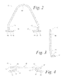
- Figs. 1 , 2, 3, and 4 illustrate one embodiment of a spring clip 30.
- a handle 40 is provided that terminates at a first stem 50 and a second stem 60.
- Stem 50 connects handle 40 to first hook 51 and stem 60 connects handle 40 to second hook 61.
- Handle 40 in Figs. 1 and 2 is of a particular curvilinear shape that allows for hook 51 and hook 61 to be urged toward each other for installation of spring clip 30 into a slot of the light tube 70; once so installed, spring clip 30 may be released and hooks 51, 61 will attempt to return to their original respective positions, thereby engaging in a slot of the light tube 70.
- hook 51 includes a first shank 52, first elbow 53, and first tip 54.
- hook 61 includes a second shank 62, second elbow 63, and second tip 64.
- hooks 51, 61 reside in a single plane in some embodiments. Such a configuration may aid in the installation of a spring clip 30 into a slot of the light tube 70. It will be still further observed in Fig. 4 that, from a bottom view, first tip 54 and second tip 64 are non-parallel and instead splay, a configuration that, for certain applications, may aid in the installation of a spring clip 30 into a slot of the light tube 70.
- Figs. 5 and 6 illustrate another embodiment of a spring clip 30'.
- a handle 40' terminates at a first stem 50' and at a second stem 60'.
- Stem 50' connects handle 40' to first hook 51' and stem 60' connects handle 40' to second hook 61'.
- Hook 51' and hook 61' open toward each other and may be urged away from each other for installation of spring clip 30' into a pair of slots, for example 80ca, 80cb; once so installed, spring clip 30' may be released and hooks 51', 61' will attempt to return to their original respected positions, thereby engaging in pair of slots, for example 80ca, 80cb.
- hook 51' includes a first shank 52', first elbow 53', and first tip 54'.
- hook 61' includes a second shank 62', second elbow 63', and second tip 64'.
- Spring clip 30 or 30' may be made of metal, plastic, or other resilient material that would allow, first, for hooks 51, 61 or 51', 61' to be urged toward one another for installation into a slot of the light tube 70and thereafter, upon release, return to an engaged position with such slot.
- first hook 51 or second hook 61 it may be desirable for one of first hook 51 or second hook 61 to move relative to handle 40 as the first hook 51 and second hook 61 are urged together or apart from each other for installation into a slot of the light tube 70, or in a pair of slots, for example 80ca, 80cb, as the case may be, while the other of first hook 51 or second hook 61 does not move relative to handle 40.
- An example of a design providing such alternative is depicted in Fig. 5 , which includes relief 65 along second stem 60'. Relief 65 may be an indentation, notch, collar, or other feature that allows second hook 61' to move relative to handle 40' as the first hook 51' and second hook 61' are urged together or apart while first hook 51' does not move relative to handle 40'.
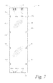
- Fig. 7 depicts a sheet member for construction a light tube 70.
- the sheet member of light tube 70 includes a first edge 83, second edge 84, third edge 85, and fourth edge 86.
- plural edge slots 80a, 80b, 80c, and 80d are illustrated.
- plural upper end slots 81a, 81b, 81c, and 81d are illustrated.
- plural lower end slots 82a, 82b, 82c, and 82d are illustrated.
- Fig. 8 depicts two embodiments of edge slot design, showing edge slot pairs 80aa, 80ab and 80ac, 80ad and 80ae, 80af together with edge slots 80b1, 80b2, 80b3.
- Fig. 9 illustrates a light tube 70 partially-assembled from the sheet member depicted in Fig. 7 .
- light tube 70 has been fabricated by rolling the sheet member upon itself so that third edge 85 overlaps fourth edge 86.
- Edge slots 80ca and 80cb have been aligned with edge slots 80aa, 80ab, or edge slots 80ac, 80ad, or edge slots 80ae, 80af (not shown).
- edge slot 80d has been aligned with edge slot 80b1, 80b2, or 80b3 (not shown).
- the first edge 83, along with upper end slots 81a, b, and lower end slot 82a are depicted.
- Fig. 10 depicts an embodiment of a completed light tube kit 20 for a skylight.
- light tube 70a has been fabricated by rolling a sheet member upon itself and secured with spring clips 30a, b.
- First edge 83a of light tube 70a is shown.
- a second light tube 70b has been similarly fabricated; first edge 83b of light tube 70b is illustrated.
- second edge (not shown) of light tube 70a has been inserted within light tube 70b beyond first edge 83b of light tube 70b.
- Light tubes 70a, 70b have then been secured together by use of spring clip 30i engaged in an upper edge slot.
- light tube 70b has been inserted within light tube 70c and light tube 70c has been inserted within light tube 70d.
- the edge slot design alternatives described above, and/or the relative sizing of spring clip 30 to the dimensions of a slot, allow light tube 70a, 70b, 70c, and 70d to be adjusted such that they are slightly tapered and thereby can be telescoped one into another.
- light tubes 70a, 70b, 70c, and 70d may be laterally adjusted relative to another, such that first edge 83a of light tube 70a is not aligned directly with second edge 84d of light tube 70d; such side-to-side adjustment of the position of first edge 83a relative to second edge 84d would allow for more complete and sound connection between an upper skylight cover and a lower skylight diffuser that had not been positioned as aligned exactly with one another.
- Fig. 11 depicts a spring clip 30 engaged with an upper slot 81 and a lower slot (not visible).
- stem 50 and stem 60 have been urged toward one another, along with their respective hooks 51 and 61 with hooks 51, 61 then inserted through the upper slot 81 and the lower slot.
- Spring clip 30 was then released, with hooks 51, 61 engaged in the upper and lower slots.
- Fig. 8 depicts elbows 53, 63 residing against the distal edges of upper slot 81.
- Fig. 12 depicts a spring clip 30' engaged with an upper slot pair 80ca, 80cb.
- stem 50' and stem 60' have been urged away from one another, along with their respective hooks 51' and 61' with hooks 51', 61' then inserted through slot 80ca and slot 80cb, respectively.
- Spring clip 30' was then released, with hooks 51', 61' engaged in slots 80ca, 80cb.
- Fig. 8 depicts shanks 52', 62' residing against the medial edges of slots 80ca, 80cb.
- a new light tube kit for a skylight is provided.
- the kit provides for installation of a tubular skylight either in new construction or into an existing building. Even in those circumstances in which the exterior cover and interior diffusor have already been installed, with the light tube to be fitted last, the present invention provides a light tube kit that may be quickly constructed yet adjusted in-place to provide for a sound finished skylight system. The system allows for a measure of side-to-side adjustment of the lower end relative to the upper end for those cases in which the interior diffusor has not been positioned exactly relative to the exterior cover. Further, the kit provides a light tube that is easily fabricated and assembled, yet can telescope upon itself so as to fully and completely span the distance between the upper cover and the lower diffusor.
- a skylight tunnel kit includes a quadrilateral sheet that defines first and second slots therethrough proximate to its perimeter.
- the sheet may be rolled upon itself to form a tube body, such that the first and second slots are aligned.
- a spring clip may be provided, having first and second hooks. This spring clip may be interfitted with the aligned slots by engaging the first hook through the first and second slots to secure the first and second slots together.
- first and second hooks open away from each other. In other embodiments, the first and second hooks open toward each other.
- the first hook resides in a first position relative to the second hook and be movable to a second position relative to the second hook, at such second position the first hook being biased toward the first position.
- the handle resides outboard of the light tunnel.
- a skylight tunnel combination includes first and second rectangular sheets, each rectangular sheet having two edge slots and one end slot defined therethrough. Each rectangular sheet may be rolled upon itself such that the two edge slots align.
- a first spring clip may be provided, the first spring clip having first and second hooks, the first hook being disposed through the two aligned edge slots and engaged therewith. Further, the first rectangular sheet may be telescoped into the second rectangular sheet such that the end slot defined through the first rectangular sheet aligns with the end slot defined through the second rectangular sheet.
- a second spring clip may be provided, the second spring clip having first and second hooks, the first hook disposed through the end slot defined through the first rectangular sheet and the end slot defined through the second rectangular sheet, and engaged therewith.
- the first hook resides in a first position relative to the second hook and be movable to a second position relative to the second hook, at such second position the first hook being biased toward the first position.
- the first and second hooks of the spring clips open away from each other and, in other embodiments, the first and second hooks open toward each other; examples of each embodiment may be used in a single skylight tunnel kit.
Landscapes
- Engineering & Computer Science (AREA)
- Architecture (AREA)
- Life Sciences & Earth Sciences (AREA)
- Sustainable Development (AREA)
- General Engineering & Computer Science (AREA)
- Non-Portable Lighting Devices Or Systems Thereof (AREA)
- Clamps And Clips (AREA)
Abstract
Description
- The present invention relates generally to a skylight light tube kit, and, more particularly, to a light tube kit for a skylight comprising a light tunnel configured from rolling a sheet upon itself and secured together with spring clips engaged through slots defined within the tube body.
- Skylights provide desirable natural lighting for building interiors, increasing visual attractiveness and reducing energy usage.
- A skylight includes a rooftop element through which sunlight enters the skylight structure, a diffuser at the building interior, and a channel between the rooftop element and diffuser to convey light from the first to the second.
- One configuration of such a skylight is a tubular skylight, in which the channel is a tube, often of circular cross-section, which may have a reflective interior surface.
- Some tubular skylights are provided with pre-assembled light tubes. However, provision of pre-assembled light tubes may be disadvantageous, in that they are bulky and therefore more difficult and more expensive to transport. Furthermore, because of the thin metal with which they are often constructed, pre-assembled light tubes may be damaged during shipment or from handling.
- Other designs of light tubes call for construction of the light tube on-site. Such designs are provided with the light tube initially as an unrolled sheet of material. At the installation site, the light tube is fabricated by rolling the sheet upon itself, overlapping two opposed edges, then installing screws through the overlapped edges. While offering certain advantages, such a design likewise suffers certain disadvantages. For example, it has been found that the force of feeding a screw through the rolled, overlapped sheet material is prone to deform the sheet material. Furthermore, this design can be assembled with the light tube inadvertently fixed at an improper diameter. Additionally, labor costs on-site are often the most expensive of those involved in building construction, but this design increases assembly time on-site and therefore increases labor costs.
-
DE 20 2005 009 483 U1 - Installation of a tubular skylight may proceed as follows. With new constructions, the building is first "weathered in," including installation of the exterior cover for the skylight at the building roof. Second, the interior ceiling is installed. It is only after those two steps are completed that a light tube itself is installed between the exterior cover and the interior ceiling. Similarly, in retrofitting a tubular skylight to an existing structure, the exterior cover would first be installed, then the interior diffusor would be installed in a room interior ceiling. Thereafter, a light tube would be configured between those two elements. In both instances, at least two challenges may be presented. First, precise placement of the diffusor relative to the exterior cover may be misjudged. Second, the precise length needed for the light tube between those two elements may be misjudged. In either circumstance, it would be desirable to have a light tube the components of which could provide side-to-side adjustment of the lower end relative to the upper end for those cases in which the diffusor has not been positioned exactly, relative to optimal placement with regard to the location of the exterior cover. Furthermore, it would be desirable to have a light tube that could be easily fabricated and 25 assembled within the space, yet telescope upon itself so as to fully and completely span the distance between those two elements.
- In response to the foregoing background, a new light tube kit for a skylight is provided. As revealed in the following description and the figures herein, this invention discovers an effective technology that simply but reliably provides for construction of a skylight tube that may be quickly constructed yet adjusted in-place to provide for a sound finished skylight system.
- In accordance with certain aspects of certain embodiments of the present technology, a light tube kit for a skylight is provided that includes a light tunnel. The light tunnel is configured from a sheet member having a first edge and a second edge that is opposite the first edge. Third and fourth edges are disposed between the first and second edges. The sheet member is rolled upon itself such that the third edge overlaps the fourth edge.
- A first slot is defined through the sheet member proximate to the third edge and a second slot is defined through the sheet member proximate to the fourth edge. With the sheet member rolled upon itself such that the third edge overlaps the fourth edge, the first and second slots are aligned.
- A spring clip is further provided. The spring clip has first and second hooks and a handle disposed between them. The first hook is disposed through the first and second slots and engaged therewith.
- In certain embodiments, the second hook is also disposed through the first and second slots and engaged therewith.
- In particular embodiments, the first slot is parallel to the third edge and the second slot is parallel to the fourth edge. A third slot is included, the third slot residing between the first slot and the third edge and being parallel to the first slot.
- In other embodiments, a third slot is included that is parallel to the first slot and located approximately the same distance from the third edge as is the first slot; a fourth slot is also included that is parallel to the second slot and located approximately the same distance from the fourth edge as is the second slot. In such embodiments, the first hook may be disposed through the first and second slots and engaged therewith and the second hook may be disposed through the third and fourth slots and engaged therewith.
- In certain embodiments, the first and second hooks open away from each other. In other embodiments, the first and second hooks open toward each other.
- In some embodiments, the first hook resides in a first position relative to the second hook and is movable to a second position relative to the second hook, at such second position the first hook being biased toward the first position.
- In particular embodiments, a slot is included that is proximate to the first edge. Likewise, for certain embodiments, the spring clip handle resides outboard of the light tunnel.
- The invention further concerns a use of a light tube kit for a skylight according to the invention in a skylight comprising a rooftop element, a diffusor and a light tube between the rooftop element and diffuser to convey light from the rooftop element to the diffusor.
- The invention further concerns a use of a light tube kit for a skylight according to the invention for installation of a tubular skylight in a new construction or in an existing building.
- The invention further concerns a method for installation of a tubular skylight in a building comprising the steps of:
- installing an exterior cover for the skylight at a roof of the building,
- installing an interior diffusor in an interior ceiling of the building, and
- installing a light tube kit for a skylight according to the invention between the exterior cover and the interior diffusor.
- The invention further concerns a skylight comprising a rooftop element through which sunlight enters the skylight, a diffuser at a building interior, and a a light tube kit for a skylight according to the invention between the rooftop element and the diffuser to convey light from the rooftop element to the diffuser.
- The preceding description sets forth certain features of the present invention so that the detailed description below may be better understood and so that the contributions of this invention may be better appreciated. Additional advantages of the invention will be set forth in part in the detailed description below, and in part, may be obvious from the detailed description or may be learned by practicing the invention. The advantages of the invention will be realized by means of the elements and combinations particularly pointed out in the appended claims. It is to be understood that both the foregoing general description as well as the following detailed description are only examples and are merely explanatory, not restrictive of the invention.
- The details of the present technology, both as to its structure and operation, can be better understood with reference to the accompanying figures. It should be noted that these figures are not necessarily to scale in all instances.
-
Fig. 1 is a perspective view of an embodiment of a spring clip in accordance with certain aspects of the present invention; -
Fig. 2 is a front elevation view of an embodiment of a spring clip in accordance with certain aspects of the present invention; -
Fig. 3 is a right side elevation view of an embodiment of a spring clip in accordance with certain aspects of the present invention; -
Fig. 4 is a bottom view of an embodiment of a spring clip in accordance with certain aspects of the present invention; -
Fig. 5 is a perspective view of an embodiment of a spring clip in accordance with certain aspects of the present invention; -
Fig. 6 is a bottom view of an embodiment of a spring clip in accordance with certain aspects of the present invention; -
Fig. 7 is a plan view of an embodiment of a sheet member for a light tunnel in accordance with certain aspects of the present invention; -
Fig. 8 is an enlarged perspective view of an embodiment of slots in a light tube kit for a skylight, taken at A inFig. 7 ; -
Fig. 9 is a perspective view of an embodiment of a light tunnel in accordance with certain aspects of the present invention; -
Fig. 10 is a perspective view of an embodiment of a light tube kit for a skylight in accordance with certain aspects of the present invention; -
Fig. 11 is an enlarged perspective view of an embodiment of a spring clip in a light tube kit for a skylight, taken at B inFig. 10 ; and -
Fig. 12 is an enlarged perspective view of an embodiment of a spring clip in a light tube kit for a skylight, taken at C inFig. 10 . - Selected combinations of aspects of the disclosed technology correspond to a plurality of different embodiments of the present invention. It should be noted that each of the exemplary embodiments presented and discussed herein should not insinuate limitations of the present subject matter. Features illustrated or described as part of one embodiment may be used in combination with aspects of another embodiment, to yield yet further embodiments. Certain features may be interchanged with similar devices or features not expressly mentioned, which perform the same or similar function. It is to be understood that this invention is not limited to the specific devices and methods disclosed herein unless otherwise specified. It is to be understood also that the terminology used herein is for the purpose of describing particular aspects only and is not intended to be limiting.
- A
light tube kit 20 for a skylight is provided.Kit 20 includes aspring clip 30 andlight tube 70. -
Spring clip 30 includes ahandle 40 that terminates at one end at afirst stem 50 and, at the other end, at asecond stem 60.Stem 50 connects handle 40 to afirst hook 51 and stem 60 connects handle 40 to asecond hook 61. In certain embodiments,first hook 51 includes afirst shank 52,first elbow 53, andfirst tip 54 andsecond hook 61 includes asecond shank 62, a second elbow 63, and asecond tip 64.First hook 51 andsecond hook 61 may open away from each other or may open toward each other. - For installation with a
light tube 70,first hook 51 andsecond hook 61 may be urged toward each other relative to handle 40 (ifhook 51 andsecond hook 61 open away from each other) or urged away from each other relative to handle 40 (ifhook 51 andsecond hook 61 open toward each other). In some embodiments, advantageouslyfirst hook 51 resides in a first position relative tosecond hook 61 and is movable to a second position relative tosecond hook 61 at whichfirst hook 51 is biased toward the first position. -
Light tube 70 may be fabricated from a sheet member. The sheet member may be of any suitable material, for example, metal. In certain embodiments, it may be desirable that at least one surface of the sheet member, that surface which will be the interior surface oflight tube 70 when assembled, be coated or treated so as to be reflective of visible light. -
Light tube 70 includes plural edge slots. Furthermore, in some embodiments lighttube 70 includes upper end slots 81 and, in particular embodiments, includes lower end slots 82. - The sheet member for
light tube 70 has afirst edge 83,second edge 84,third edge 85, andfourth edge 86. The use of edge slots may be of several designs in alight tube 70. - For example, a
first edge slot 80b resides, singly, proximate tothird edge 85 and asecond edge slot 80d resides, singly, proximate tofourth edge 86. Alight tube 70 of such a design may be fabricated by rolling the sheet member upon itself so thatthird edge 85 overlapsfourth edge 86.First edge slot 80b is thereby aligned withsecond edge slot 80d. Once aligned, aspring clip 30 is used to securethird edge 85 withfourth edge 86, thereby creating alight tube 70. More particularly, aspring clip 30 with first andsecond hooks edge slots first hook 51 andsecond hook 61 engage throughedge slots first hook 51 wraps around one end of alignededge slots first shank 52 resides outboard ofedge slots first tip 54 resides inboard ofedge slots second hook 61 wraps around the other end of alignededge slots second shank 62 resides outboard ofedge slots second tip 64 reside inboard ofedge slots third edge 85 thereby being secured withfourth edge 86, creating alight tube 70. - A second design of edge slots may be used in a
light tube 70, in alternative to or in conjunction with the design described in the preceding paragraph. With such second design, a first pair of edge slots 80aa, 80ab resides proximate tothird edge 85 and a second pair of edge slots 80ca, 80cb resides proximate tofourth edge 86. Edge slot pair 80aa, 80ab includes a first edge slot 80aa parallel to a second edge slot 80ab, edge slots 80aa, 80ab residing approximately equidistant from third edge 85 (with the ends of edge slots 80aa, 80ab closest to each another understood to be the respective medial ends and the opposite ends understood to be the respective distal ends). Likewise, edge slot pair 80ca, 80cb includes a first edge slot 80ca parallel to a second edge slot 80cb, edge slots 80ca, 80cb residing approximately equidistant fromfourth edge 86. Alight tube 70 of such a design may be fabricated by rolling the sheet member upon itself so thatthird edge 85 overlapsfourth edge 86. Edge slot 80aa is thereby aligned with edge slot 80ca and edge slot 80ab is thereby aligned with edge slot 80cb. Once so aligned, aspring clip 30 is interfitted into aligned edge slots 80aa, 80ca and 80ab, 80cb. For example, with aspring clip 30 in whichfirst hook 51 andsecond hook 61 open away from each other,first hook 51 wraps around the distal ends of aligned edge slots 80ca, 80aa such thatfirst shank 52 resides outboard of edge slots 80ca, 80aa andfirst tip 54 resides inboard of edge slots 80ca, 80aa; similarly,second hook 61 wraps around the distal ends of aligned edge slots 80cb, 80ab such thatsecond shank 62 resides outboard of edge slots 80cb, 80ab andsecond tip 64 resides inboard of edge slots 80cb, 80ab;third edge 85 thereby being secured withfourth edge 86, creating alight tube 70. Alternatively, with aspring clip 30 in whichfirst hook 51 andsecond hook 61 open toward each other,first hook 51 wraps around the medial ends of aligned edge slots 80ca, 80aa such thatfirst shank 52 resides outboard of edge slots 80ca, 80aa andfirst tip 54 resides inboard of edge slots 80ca, 80aa; similarly,second hook 61 wraps around the medial ends of aligned edge slots 80cb, 80ab such thatsecond shank 62 resides outboard of edge slots 80cb, 80ab andsecond tip 64 reside inboard of edge slots 80cb, 80ab;third edge 85 thereby being secured withfourth edge 86, creating alight tube 70. - The
light tube kit 20 may be further configured for telescoping alight tube 70a into a secondlight tube 70b. Such a configuration may be achieved as follows. Edge slots are dimensioned such that they are wider thanhooks spring clip 30. In one embodiment, for example, edge slots may be 3 - 4 millimeters in width whereashooks third edge 85 withfourth edge 86 may be adjusted by movingthird edge 85 relative tofourth edge 86, even withspring clip 30 installed, such thatlight tube 70 becomes slightly tapered or frusto-conical. Such dimensioning and such latitude allows for alight tube 70 to achieve a nominal diameter, yet allows small adjustment of such diameter as circumstances may require. By adjustment of the overlap ofthird edge 85 withfourth edge 86, as allowed by the relative dimensioning of a slot and hooks 51, 61,light tube 70 may be tapered so as to allow one end of alight tube 70a to be inserted into another end of a secondlight tube 70b. Further, by including one or more slots along afirst edge 83 and/orsecond edge 84 of eachlight tube light tubes spring clip 30 interfitted between overlapping edge slots, for example, 81c, 82c, oflight tubes - Alternatively, or additionally,
light tube kit 20 may be configured for telescoping alight tube 70a into a secondlight tube 70b with different designs of edge slots. A first edge slot 80b3 may be included proximate tothird edge 85. A second edge slot 80b2 may be included between first edge slot 80b3 andthird edge 85 and generally parallel to first edge slot 80b3. For some applications, additional edge slots, for example edge slot 80b1, may be included between second edge slot 80b2 andthird edge 85. Alight tube 70 of such a design may be fabricated by rolling the sheet member upon itself so thatthird edge 85 overlapsfourth edge 86. Edge slot 80b3 may thereby be aligned withedge slot 80d to fabricate alight tube 70 of a particular diameter, or edge slot 80b2 may thereby be aligned withedge slot 80d to fabricate alight tube 70 of a larger diameter (or edge slot 80b1 may thereby be aligned withedge slot 80d to fabricate alight tube 70 of a still larger third diameter); once aligned, aspring clip 30 may be used to securethird edge 85 withfourth edge 86, thereby creating alight tube 70.Light tube 70 may thereby be selectively cylindrical or conical, depending upon user choice for a given application. - A further design of edge slots may be used in a
light tube 70, in alternative to or in conjunction with the designs previously described. Particularly, a first pair of edge slots 80ae, 80af may reside proximate tothird edge 85. Edge slot pair 80ae, 80af may include edge slot 80ae parallel to edge slot 80af, edge slots 80ae, 80af residing approximately equidistant fromthird edge 85. A second pair of edge slots 80ca, 80cb may reside proximate tofourth edge 86. Edge slot pair 80ca, 80cb may include edge slot 80ca parallel to edge slot 80cb, edge slots 80ca, 80cb residing approximately equidistant fromfourth edge 86. A third pair of edge slots, 80ac, 80ad may be included between first pair of edge slots 80ae, 80af andthird edge 85 and generally parallel to first pair of edge slots 80ae, 80af. For some applications, additional pairs of edge slots, for example edge slots 80aa, 80ab, may be included between third pair of edge slots, 80ac, 80ad andthird edge 85. Alight tube 70 of such a design may be fabricated by rolling the sheet member upon itself so thatthird edge 85 overlapsfourth edge 86. Edge slots 80ae, 80af may thereby be aligned with edge slots 80ca, 80cb, respectively, to fabricate alight tube 70 of a particular diameter, or edge slots 80ac, 80ad may thereby be aligned with edge slots 80ca, 80cb, respectively, to fabricate alight tube 70 of a larger diameter (or edge slots 80aa, 80ab may thereby be aligned with edge slots 80ca, 80cb, respectively, to fabricate alight tube 70 of a still larger third diameter); once aligned, aspring clip 30 may be used to securethird edge 85 withfourth edge 86, thereby creating alight tube 70.Light tube 70 may thereby be selectively cylindrical or conical, depending upon user choice for a given application. -
Figs. 1 ,2, 3, and 4 illustrate one embodiment of aspring clip 30. Ahandle 40 is provided that terminates at afirst stem 50 and asecond stem 60.Stem 50 connects handle 40 tofirst hook 51 and stem 60 connects handle 40 tosecond hook 61.Handle 40 inFigs. 1 and2 is of a particular curvilinear shape that allows forhook 51 andhook 61 to be urged toward each other for installation ofspring clip 30 into a slot of thelight tube 70; once so installed,spring clip 30 may be released and hooks 51, 61 will attempt to return to their original respective positions, thereby engaging in a slot of thelight tube 70. The particular curvilinear geometry of thehandle 40 illustrated inFigs. 1 - 4 is not by limitation; any geometry that would allowhooks light tube 70 and engage therethrough may be utilized. It will be observed inFigs. 1 ,2, 3, and 4 that hook 51 includes afirst shank 52,first elbow 53, andfirst tip 54. Similarly,hook 61 includes asecond shank 62, second elbow 63, andsecond tip 64. - It will be further observed in
Fig. 2 that, from a front elevation view, hooks 51, 61 reside in a single plane in some embodiments. Such a configuration may aid in the installation of aspring clip 30 into a slot of thelight tube 70. It will be still further observed inFig. 4 that, from a bottom view,first tip 54 andsecond tip 64 are non-parallel and instead splay, a configuration that, for certain applications, may aid in the installation of aspring clip 30 into a slot of thelight tube 70. -
Figs. 5 and 6 illustrate another embodiment of a spring clip 30'. A handle 40' terminates at a first stem 50' and at a second stem 60'. Stem 50' connects handle 40' to first hook 51' and stem 60' connects handle 40' to second hook 61'. Hook 51' and hook 61' open toward each other and may be urged away from each other for installation of spring clip 30' into a pair of slots, for example 80ca, 80cb; once so installed, spring clip 30' may be released and hooks 51', 61' will attempt to return to their original respected positions, thereby engaging in pair of slots, for example 80ca, 80cb. It will be observed inFigs. 5 and 6 that hook 51' includes a first shank 52', first elbow 53', and first tip 54'. Similarly, hook 61' includes a second shank 62', second elbow 63', and second tip 64'. -
Spring clip 30 or 30' may be made of metal, plastic, or other resilient material that would allow, first, forhooks - The subject invention further teaches that, with some applications, it may be desirable for one of
first hook 51 orsecond hook 61 to move relative to handle 40 as thefirst hook 51 andsecond hook 61 are urged together or apart from each other for installation into a slot of thelight tube 70, or in a pair of slots, for example 80ca, 80cb, as the case may be, while the other offirst hook 51 orsecond hook 61 does not move relative to handle 40. An example of a design providing such alternative is depicted inFig. 5 , which includesrelief 65 along second stem 60'.Relief 65 may be an indentation, notch, collar, or other feature that allows second hook 61' to move relative to handle 40' as the first hook 51' and second hook 61' are urged together or apart while first hook 51' does not move relative to handle 40'. -
Fig. 7 depicts a sheet member for construction alight tube 70. The sheet member oflight tube 70 includes afirst edge 83,second edge 84,third edge 85, andfourth edge 86. In the embodiment depicted inFig. 7 ,plural edge slots upper end slots lower end slots -
Fig. 8 depicts two embodiments of edge slot design, showing edge slot pairs 80aa, 80ab and 80ac, 80ad and 80ae, 80af together with edge slots 80b1, 80b2, 80b3. -
Fig. 9 illustrates alight tube 70 partially-assembled from the sheet member depicted inFig. 7 . As depicted inFig. 8 ,light tube 70 has been fabricated by rolling the sheet member upon itself so thatthird edge 85 overlapsfourth edge 86. Edge slots 80ca and 80cb have been aligned with edge slots 80aa, 80ab, or edge slots 80ac, 80ad, or edge slots 80ae, 80af (not shown). Further,edge slot 80d has been aligned with edge slot 80b1, 80b2, or 80b3 (not shown). For illustration, thefirst edge 83, along withupper end slots 81a, b, andlower end slot 82a, are depicted. -
Fig. 10 depicts an embodiment of a completedlight tube kit 20 for a skylight. In the embodiment shown,light tube 70a has been fabricated by rolling a sheet member upon itself and secured withspring clips 30a, b.First edge 83a oflight tube 70a is shown. Similarly, a secondlight tube 70b has been similarly fabricated;first edge 83b oflight tube 70b is illustrated. In the kit depicted inFig. 7 , second edge (not shown) oflight tube 70a has been inserted withinlight tube 70b beyondfirst edge 83b oflight tube 70b.Light tubes light tube 70b has been inserted withinlight tube 70c andlight tube 70c has been inserted withinlight tube 70d. The edge slot design alternatives described above, and/or the relative sizing ofspring clip 30 to the dimensions of a slot, allowlight tube spring clips 30i, 30j, and 30k,light tubes first edge 83a oflight tube 70a is not aligned directly with second edge 84d oflight tube 70d; such side-to-side adjustment of the position offirst edge 83a relative to second edge 84d would allow for more complete and sound connection between an upper skylight cover and a lower skylight diffuser that had not been positioned as aligned exactly with one another. -
Fig. 11 depicts aspring clip 30 engaged with an upper slot 81 and a lower slot (not visible). For installation, stem 50 and stem 60 have been urged toward one another, along with theirrespective hooks hooks Spring clip 30 was then released, withhooks Fig. 8 depictselbows 53, 63 residing against the distal edges of upper slot 81. -
Fig. 12 depicts a spring clip 30' engaged with an upper slot pair 80ca, 80cb. For installation, stem 50' and stem 60' have been urged away from one another, along with their respective hooks 51' and 61' with hooks 51', 61' then inserted through slot 80ca and slot 80cb, respectively. Spring clip 30' was then released, with hooks 51', 61' engaged in slots 80ca, 80cb. It will be seen thatFig. 8 depicts shanks 52', 62' residing against the medial edges of slots 80ca, 80cb. - From this disclosure, a new light tube kit for a skylight is provided. The kit provides for installation of a tubular skylight either in new construction or into an existing building. Even in those circumstances in which the exterior cover and interior diffusor have already been installed, with the light tube to be fitted last, the present invention provides a light tube kit that may be quickly constructed yet adjusted in-place to provide for a sound finished skylight system. The system allows for a measure of side-to-side adjustment of the lower end relative to the upper end for those cases in which the interior diffusor has not been positioned exactly relative to the exterior cover. Further, the kit provides a light tube that is easily fabricated and assembled, yet can telescope upon itself so as to fully and completely span the distance between the upper cover and the lower diffusor.
- The embodiments of the present invention described above are not exhaustive nor do they limit the invention to the precise forms disclosed. Rather, the described embodiments are chosen so that others skilled in the art to which this invention pertains may appreciate and understand the principles and practice of the present invention. The scope of the present invention fully encompasses other embodiments that may become obvious to those skilled in the art and is, accordingly, to be limited by nothing more than the appended claims.
- For instance, in accordance with yet additional aspects of other embodiments of the present technology, a skylight tunnel kit is provided. The kit includes a quadrilateral sheet that defines first and second slots therethrough proximate to its perimeter. The sheet may be rolled upon itself to form a tube body, such that the first and second slots are aligned.
- A spring clip may be provided, having first and second hooks. This spring clip may be interfitted with the aligned slots by engaging the first hook through the first and second slots to secure the first and second slots together.
- In specific embodiments, the first and second hooks open away from each other. In other embodiments, the first and second hooks open toward each other.
- In certain embodiments, the first hook resides in a first position relative to the second hook and be movable to a second position relative to the second hook, at such second position the first hook being biased toward the first position.
- In particular embodiments, the handle resides outboard of the light tunnel.
- In accordance with still further aspects of other embodiments of the present technology, a skylight tunnel combination is provided. The combination includes first and second rectangular sheets, each rectangular sheet having two edge slots and one end slot defined therethrough. Each rectangular sheet may be rolled upon itself such that the two edge slots align. A first spring clip may be provided, the first spring clip having first and second hooks, the first hook being disposed through the two aligned edge slots and engaged therewith. Further, the first rectangular sheet may be telescoped into the second rectangular sheet such that the end slot defined through the first rectangular sheet aligns with the end slot defined through the second rectangular sheet. A second spring clip may be provided, the second spring clip having first and second hooks, the first hook disposed through the end slot defined through the first rectangular sheet and the end slot defined through the second rectangular sheet, and engaged therewith.
- In particular embodiments, the first hook resides in a first position relative to the second hook and be movable to a second position relative to the second hook, at such second position the first hook being biased toward the first position. In some embodiments, the first and second hooks of the spring clips open away from each other and, in other embodiments, the first and second hooks open toward each other; examples of each embodiment may be used in a single skylight tunnel kit.
Claims (15)
- A light tube kit (20) for a skylight, comprising:a light tunnel (70), the light tunnel being configured from a sheet member having a first edge (83) and a second edge (84) opposite the first edge, with opposed third (85) and fourth (86) edges disposed between the first and second edges, the sheet member being rolled upon itself such that the third edge overlaps the fourth edge;a first slot (80b) defined through the sheet member proximate to the third edge and a second slot (80d) defined through the sheet member proximate to the fourth edge, the first and second slots being aligned;a spring clip (30, 30'), the spring clip having first (51, 51') and second (61, 61') hooks and a handle (40, 40') disposed therebetween; andthe first hook (51, 51') being disposed through the first and second slots (80b, 80d) and engaged therewith.
- The light tube kit for a skylight of Claim 1, wherein the second hook (61, 61') is disposed through the first and second slots (80b, 80d) and engaged therewith.
- The light tube kit for a skylight of Claim 1, wherein the first slot is parallel to the third edge and the second slot is parallel to the fourth edge.
- The light tube kit for a skylight of Claim 1, further including a third slot (80b2) residing between the first slot and the third edge and being parallel to the first slot.
- The light tube kit for a skylight of Claim 1, further including a third slot (80a) parallel to the first slot (80b) and residing equidistant from the third edge (85) with the first slot and a fourth slot (80c) parallel to the second slot (80d) and residing equidistant from the fourth edge (86) with the second slot.
- The light tube kit for a skylight of Claim 5, in which the second hook (61, 61') is disposed through the third and fourth slots (80a, 80c) and engaged therewith.
- The light tube kit for a skylight of Claim 1, wherein the first and second hooks are open away from each other.
- The light tube kit for a skylight of Claim 1, wherein the first and second hooks are open toward each other.
- The light tube kit for a skylight of Claim 1, wherein the first hook resides in a first position relative to the second hook, the first hook being movable to a second position relative to the second hook at which the first hook is biased toward the first position.
- The light tube kit for a skylight of Claim 1, further including a slot (81a, 81b, 81c, 81d) proximate to the first edge.
- The light tube kit for a skylight of Claim 1, wherein the handle resides outboard of the light tunnel.
- Use of a light tube kit (20) for a skylight according to any one of claims 1 to 11 in a skylight comprising a rooftop element, a diffusor and a light tube between the rooftop element and diffuser to convey light from the rooftop element to the diffusor.
- Use of a light tube kit (20) for a skylight according to any one of claims 1 to 11 for installation of a tubular skylight in a new construction or in an existing building.
- Method for installation of a tubular skylight in a building comprising the steps of:installing an exterior cover for the skylight at a roof of the building,installing an interior diffusor in an interior ceiling of the building, andinstalling a light tube kit (20) for a skylight according to any one of claims 1 to 11 between the exterior cover and the interior diffusor.
- A skylight comprising a rooftop element through which sunlight enters the skylight, a diffuser at a building interior, and a light tube kit (20) for a skylight according to any one of claims 1 to 11 between the rooftop element and the diffuser to convey light from the rooftop element to the diffuser.
Applications Claiming Priority (1)
| Application Number | Priority Date | Filing Date | Title |
|---|---|---|---|
| US13/837,229 US9482399B2 (en) | 2013-03-15 | 2013-03-15 | Light tube kit for skylight |
Publications (3)
| Publication Number | Publication Date |
|---|---|
| EP2778513A1 true EP2778513A1 (en) | 2014-09-17 |
| EP2778513B1 EP2778513B1 (en) | 2016-05-25 |
| EP2778513B9 EP2778513B9 (en) | 2016-10-05 |
Family
ID=50276940
Family Applications (1)
| Application Number | Title | Priority Date | Filing Date |
|---|---|---|---|
| EP14158758.4A Active EP2778513B9 (en) | 2013-03-15 | 2014-03-11 | A light tube kit for a skylight |
Country Status (6)
| Country | Link |
|---|---|
| US (1) | US9482399B2 (en) |
| EP (1) | EP2778513B9 (en) |
| CA (1) | CA2845378C (en) |
| DK (1) | DK2778513T3 (en) |
| ES (1) | ES2580507T3 (en) |
| PL (1) | PL2778513T3 (en) |
Families Citing this family (4)
| Publication number | Priority date | Publication date | Assignee | Title |
|---|---|---|---|---|
| USD934428S1 (en) * | 2020-02-10 | 2021-10-26 | Endomagnetics Ltd | Tetrahedral marker |
| USD935028S1 (en) * | 2020-02-23 | 2021-11-02 | Endomagnetics Ltd | Four sided tetrahedral |
| US12577782B1 (en) | 2021-01-25 | 2026-03-17 | Michael Brent Powers | Safety cages for protecting tubular skylights |
| GB2610432A (en) * | 2021-09-07 | 2023-03-08 | Suntile Uk Ltd | Light directing apparatus and method |
Citations (2)
| Publication number | Priority date | Publication date | Assignee | Title |
|---|---|---|---|---|
| US6321493B1 (en) * | 1999-10-07 | 2001-11-27 | Solatube International Inc. | Systems and methods for connecting skylight components |
| DE202005009483U1 (en) | 2005-06-16 | 2005-09-08 | Vkr Holding A/S | Component for forming of tubular-form connecting passage has set of first connecting devices, especially slots, provided along first edge, and set of second connecting devices, especially tabs, provided along second edge |
Family Cites Families (64)
| Publication number | Priority date | Publication date | Assignee | Title |
|---|---|---|---|---|
| US669929A (en) * | 1900-08-21 | 1901-03-12 | Richard G Johnson | Shutter-bower. |
| US1190759A (en) * | 1915-05-17 | 1916-07-11 | Waverly Heating And Supply Company | Sheet-metal joint. |
| US2160009A (en) * | 1936-07-29 | 1939-05-30 | Owens Corning Fiberglass Corp | Pipe covering |
| US2463079A (en) * | 1944-09-16 | 1949-03-01 | Albrecht Paul | Attachable brace and garment connector |
| US4146048A (en) * | 1977-05-02 | 1979-03-27 | Prefco Productions, Inc. | Fire damper and method of fabrication |
| US4221039A (en) * | 1978-05-08 | 1980-09-09 | Smith Harman S | Gasket holder clip |
| US4733987A (en) * | 1986-02-27 | 1988-03-29 | Tomlinson Peter N | Spring clip |
| US5099622A (en) | 1986-10-20 | 1992-03-31 | Continuum Developments Pty Limited | Skylight |
| US4809468A (en) | 1987-04-24 | 1989-03-07 | Bareiss Raymond E | Light transmitter interconnecting a skylight and a ceiling opening |
| BR9300902A (en) * | 1992-05-20 | 1993-11-23 | Avco Corp | FIRE PROOF PANEL, METHODS TO MAKE A FIRE PROOF PANEL AND FIRE PROOF PANELS AND STRUCTURAL MEMBER OF A HYDROCARBON INDUSTRY PLATFORM |
| AU677720B2 (en) | 1993-10-11 | 1997-05-01 | Skydome Industries Limited | Adjustable skylight |
| US5502935A (en) * | 1994-07-18 | 1996-04-02 | Demmer; Albert J. | Roof to ceiling skylight apparatus |
| US5546712A (en) | 1994-11-03 | 1996-08-20 | Bixby; Joseph A. | System and method of constructing a skylight |
| US5595427A (en) * | 1996-02-13 | 1997-01-21 | Transfer Flow International, Inc. | Modular countertop |
| JPH09265915A (en) * | 1996-03-29 | 1997-10-07 | Nec Kansai Ltd | Inner shield coupling clamp |
| USD382347S (en) | 1996-06-04 | 1997-08-12 | Sunlight Systems, Inc. | Tubular skylight |
| US5655339A (en) | 1996-08-09 | 1997-08-12 | Odl, Incorporated | Tubular skylight with improved dome |
| US6528782B1 (en) | 1996-08-20 | 2003-03-04 | Schott Donnelly Llc | Chromogenic light filter and controls |
| US5878539A (en) | 1997-06-09 | 1999-03-09 | Grubb; Dennis | Method and apparatus for a tubular skylight system |
| US5896712A (en) * | 1997-10-24 | 1999-04-27 | Solatube International, Inc. | Light-collecting skylight cover |
| US5896713A (en) | 1997-11-13 | 1999-04-27 | Solatube International, Inc. | Tubular skylight with vertically adjustable tube and improved roof cover seal |
| US5983581A (en) | 1998-05-22 | 1999-11-16 | Odl, Incorporated | Tubular skylight with offset dome |
| US6256947B1 (en) | 1998-06-04 | 2001-07-10 | Solatube International, Inc. | Method and apparatus for a tubular skylight system |
| US6035593A (en) | 1998-07-30 | 2000-03-14 | Solatube International, Inc. | Tubular skylight with snap assembly and expansion spacer |
| US7159364B2 (en) | 1998-07-30 | 2007-01-09 | Solatube International, Inc. | Skylight flashing |
| US6363667B2 (en) | 1999-03-18 | 2002-04-02 | O'neill Mark | Passive collimating tubular skylight |
| US6219977B1 (en) | 1999-05-05 | 2001-04-24 | Solatube International, Inc. | Tubular skylight with round-to-square adaptor |
| AUPQ024099A0 (en) * | 1999-05-07 | 1999-06-03 | Promat Fyreguard Pty Ltd | Service shut off device |
| US6142645A (en) | 1999-07-19 | 2000-11-07 | Han; Mike | Skylight system |
| USD464436S1 (en) | 1999-11-19 | 2002-10-15 | Fox Lite, Inc. | Collapsible skylight tube having open ends and a light reflecting inner surface |
| US7120971B2 (en) * | 2001-03-02 | 2006-10-17 | Newfrey Llc | Low insertion effort u-base retainer |
| US7146768B2 (en) | 2001-03-30 | 2006-12-12 | Solatube International, Inc. | Skylight tube with reflective film and surface irregularities |
| US7784159B2 (en) * | 2002-06-07 | 2010-08-31 | Termax Corporation | Fastener with ergonomic removal to insertion force ratio |
| US6990773B2 (en) | 2001-06-29 | 2006-01-31 | Michael Borges | Flexible reflective skylight tubes |
| US20030000159A1 (en) | 2001-06-29 | 2003-01-02 | Estrada Lugardo R. | Skylight with heat-and moisture-releasing grooves |
| US20030066254A1 (en) | 2001-10-04 | 2003-04-10 | Deblock David A. | Tubular skylight with improved one-piece curb and tube |
| US7185464B2 (en) | 2001-10-29 | 2007-03-06 | Gennaro Bracale | Tubular skylight for lighting rooms with natural light |
| US6523483B1 (en) * | 2002-01-16 | 2003-02-25 | Holland Company | Cement hopper car hatch anti-accumulator |
| US7234279B2 (en) | 2002-04-26 | 2007-06-26 | Sun-Tek Manufacturing Inc. | Multi-tube skylight |
| US6813864B2 (en) | 2002-07-01 | 2004-11-09 | Epic Metals Corporation | Decking for receipt of skylights |
| US7322156B1 (en) | 2002-07-12 | 2008-01-29 | Solatube International, Inc. | Skylight domes with reflectors |
| US6623137B1 (en) | 2002-08-30 | 2003-09-23 | Marsonette, Inc. | Lighting system |
| US7757444B1 (en) | 2003-01-31 | 2010-07-20 | Sun Bulb, Inc. | Skylight system |
| US7082726B2 (en) | 2003-07-07 | 2006-08-01 | Solatube International, Inc. | Butterfly valve for skylight |
| US6918216B2 (en) | 2003-08-20 | 2005-07-19 | Fox Lite, Inc. | Tubular skylight assembly |
| US7168211B2 (en) | 2003-09-02 | 2007-01-30 | Solatube International, Inc. | Tubular skylight with dome flashing and protective waffle pattern corrugation |
| US7040061B2 (en) | 2003-09-02 | 2006-05-09 | Solatube International, Inc. | Tubular skylight with dome flashing and protective corrugation |
| US8555571B2 (en) * | 2004-01-09 | 2013-10-15 | Vkr Holding A/S | Skylight with displacement absorber and interlocking telescoping tubes |
| US7380377B2 (en) | 2005-01-12 | 2008-06-03 | Vkr Holding A/S | Adjustable skylight angle adaptor and system |
| US7546709B2 (en) | 2005-10-03 | 2009-06-16 | Solatube International, Inc. | Tubular skylight dome with variable prism |
| US20070266652A1 (en) | 2006-05-22 | 2007-11-22 | Paul Jaster | Skylight tube with reflective structured surface |
| US7954281B2 (en) | 2006-11-08 | 2011-06-07 | Solatube International, Inc. | Skylight tube with infrared heat transfer |
| US8376600B2 (en) * | 2007-06-29 | 2013-02-19 | Orion Energy Systems, Inc. | Lighting device |
| US7976189B2 (en) | 2007-09-29 | 2011-07-12 | Ian Osborn | Skylight LED lighting system |
| JP5406823B2 (en) | 2008-03-05 | 2014-02-05 | 東洋鋼鈑株式会社 | Optical transmission equipment |
| FR2930976B1 (en) * | 2008-05-07 | 2013-06-21 | Raymond A & Cie | FASTENING CLAMP OF TWO PIECES ON ONE ANOTHER |
| US20100251621A1 (en) * | 2009-04-01 | 2010-10-07 | Electrolux Home Products, Inc. | Door seal clip |
| US7957065B2 (en) | 2009-06-04 | 2011-06-07 | Solatube International, Inc. | Skylight collimator with multiple stages |
| US8098433B2 (en) | 2009-12-11 | 2012-01-17 | Solatube International, Inc. | Direct and indirect light diffusing devices and methods |
| US8083363B2 (en) | 2009-08-20 | 2011-12-27 | Solatube International, Inc. | Daylighting devices and methods with auxiliary lighting fixtures |
| US8896924B2 (en) * | 2012-05-04 | 2014-11-25 | Abl Ip Holding, Llc | Tubular daylighting system |
| AU2012203297B1 (en) * | 2012-06-05 | 2013-05-09 | Rodric Lindsay Fooks | Skylight Dome |
| US8982467B2 (en) * | 2012-12-11 | 2015-03-17 | Solatube International, Inc. | High aspect ratio daylight collectors |
| US8958157B2 (en) * | 2013-03-14 | 2015-02-17 | Solatube International, Inc. | Daylighting tube segment connection systems and methods |
-
2013
- 2013-03-15 US US13/837,229 patent/US9482399B2/en active Active
-
2014
- 2014-03-07 CA CA2845378A patent/CA2845378C/en active Active
- 2014-03-11 EP EP14158758.4A patent/EP2778513B9/en active Active
- 2014-03-11 DK DK14158758.4T patent/DK2778513T3/en active
- 2014-03-11 PL PL14158758.4T patent/PL2778513T3/en unknown
- 2014-03-11 ES ES14158758.4T patent/ES2580507T3/en active Active
Patent Citations (2)
| Publication number | Priority date | Publication date | Assignee | Title |
|---|---|---|---|---|
| US6321493B1 (en) * | 1999-10-07 | 2001-11-27 | Solatube International Inc. | Systems and methods for connecting skylight components |
| DE202005009483U1 (en) | 2005-06-16 | 2005-09-08 | Vkr Holding A/S | Component for forming of tubular-form connecting passage has set of first connecting devices, especially slots, provided along first edge, and set of second connecting devices, especially tabs, provided along second edge |
Also Published As
| Publication number | Publication date |
|---|---|
| CA2845378C (en) | 2016-11-01 |
| ES2580507T3 (en) | 2016-08-24 |
| US20140268863A1 (en) | 2014-09-18 |
| PL2778513T3 (en) | 2016-11-30 |
| CA2845378A1 (en) | 2014-09-15 |
| US9482399B2 (en) | 2016-11-01 |
| EP2778513B9 (en) | 2016-10-05 |
| DK2778513T3 (en) | 2016-07-04 |
| EP2778513B1 (en) | 2016-05-25 |
Similar Documents
| Publication | Publication Date | Title |
|---|---|---|
| EP2778513B1 (en) | A light tube kit for a skylight | |
| US20140091588A1 (en) | Vehicular accessory retention clip, assembly, and method thereof | |
| US8820686B2 (en) | Apparatus and system to mount objects in proximity to ceiling structure | |
| US20180119907A1 (en) | Bar hanger system for recessed fixtures | |
| US8845406B2 (en) | Vent sealing device and system | |
| CN109306969A (en) | Ventilation Fan Containment and Mounting System | |
| US20130334392A1 (en) | L-shaped bracket with alignment assisting peep hole | |
| US20140167405A1 (en) | Insert for HVAC Systems | |
| US20170204999A1 (en) | Fire stop sleeve, partition provided with fire stop sleeve and method for installation for stop sleeve | |
| EP3276270A1 (en) | Vent assembly for ventilation and making method therefor | |
| EP2374954B1 (en) | Section for structures and relative structure | |
| US7360799B1 (en) | Insulation cladding for bends | |
| US20150369513A1 (en) | Check Valve for Ventilation System | |
| KR101708779B1 (en) | A piper hanger for auto-coupled Pipe | |
| EP3584510B1 (en) | A terminal device to be connected to a venthole and a method for connecting a terminal device to a venthole | |
| US10156071B2 (en) | Adaptor for installing a camera or lighting fixture | |
| EP1936265A1 (en) | Device for installing flush-fit light fittings into a surface | |
| CA2845990C (en) | Access panels | |
| JP5513298B2 (en) | Arrangement body fixing tool | |
| US20120079649A1 (en) | Toilet Installation Guide | |
| CA2379170A1 (en) | Vane rail and its assembly for an air duct | |
| CN102678706A (en) | Furniture splicing structure | |
| GB2528971A (en) | Water diversion device | |
| KR20170084651A (en) | Wire holding device to install display system in pair glass | |
| JP3915803B2 (en) | Air supply / exhaust port |
Legal Events
| Date | Code | Title | Description |
|---|---|---|---|
| 17P | Request for examination filed |
Effective date: 20140311 |
|
| AK | Designated contracting states |
Kind code of ref document: A1 Designated state(s): AL AT BE BG CH CY CZ DE DK EE ES FI FR GB GR HR HU IE IS IT LI LT LU LV MC MK MT NL NO PL PT RO RS SE SI SK SM TR |
|
| AX | Request for extension of the european patent |
Extension state: BA ME |
|
| PUAI | Public reference made under article 153(3) epc to a published international application that has entered the european phase |
Free format text: ORIGINAL CODE: 0009012 |
|
| R17P | Request for examination filed (corrected) |
Effective date: 20150304 |
|
| RBV | Designated contracting states (corrected) |
Designated state(s): AL AT BE BG CH CY CZ DE DK EE ES FI FR GB GR HR HU IE IS IT LI LT LU LV MC MK MT NL NO PL PT RO RS SE SI SK SM TR |
|
| RIC1 | Information provided on ipc code assigned before grant |
Ipc: F21S 11/00 20060101AFI20151020BHEP |
|
| GRAP | Despatch of communication of intention to grant a patent |
Free format text: ORIGINAL CODE: EPIDOSNIGR1 |
|
| INTG | Intention to grant announced |
Effective date: 20151210 |
|
| GRAS | Grant fee paid |
Free format text: ORIGINAL CODE: EPIDOSNIGR3 |
|
| GRAA | (expected) grant |
Free format text: ORIGINAL CODE: 0009210 |
|
| AK | Designated contracting states |
Kind code of ref document: B1 Designated state(s): AL AT BE BG CH CY CZ DE DK EE ES FI FR GB GR HR HU IE IS IT LI LT LU LV MC MK MT NL NO PL PT RO RS SE SI SK SM TR |
|
| REG | Reference to a national code |
Ref country code: GB Ref legal event code: FG4D |
|
| RIN1 | Information on inventor provided before grant (corrected) |
Inventor name: RONAN, JOSEPH JEFFREY Inventor name: RUHOFF, ALAN JOHN Inventor name: RIMSKY, CHARLES JOSEPH |
|
| REG | Reference to a national code |
Ref country code: CH Ref legal event code: EP |
|
| REG | Reference to a national code |
Ref country code: IE Ref legal event code: FG4D Ref country code: AT Ref legal event code: REF Ref document number: 802637 Country of ref document: AT Kind code of ref document: T Effective date: 20160615 |
|
| REG | Reference to a national code |
Ref country code: DK Ref legal event code: T3 Effective date: 20160628 |
|
| REG | Reference to a national code |
Ref country code: DE Ref legal event code: R096 Ref document number: 602014002026 Country of ref document: DE |
|
| REG | Reference to a national code |
Ref country code: ES Ref legal event code: FG2A Ref document number: 2580507 Country of ref document: ES Kind code of ref document: T3 Effective date: 20160824 Ref country code: NL Ref legal event code: FP |
|
| REG | Reference to a national code |
Ref country code: LT Ref legal event code: MG4D |
|
| PG25 | Lapsed in a contracting state [announced via postgrant information from national office to epo] |
Ref country code: FI Free format text: LAPSE BECAUSE OF FAILURE TO SUBMIT A TRANSLATION OF THE DESCRIPTION OR TO PAY THE FEE WITHIN THE PRESCRIBED TIME-LIMIT Effective date: 20160525 Ref country code: LT Free format text: LAPSE BECAUSE OF FAILURE TO SUBMIT A TRANSLATION OF THE DESCRIPTION OR TO PAY THE FEE WITHIN THE PRESCRIBED TIME-LIMIT Effective date: 20160525 Ref country code: NO Free format text: LAPSE BECAUSE OF FAILURE TO SUBMIT A TRANSLATION OF THE DESCRIPTION OR TO PAY THE FEE WITHIN THE PRESCRIBED TIME-LIMIT Effective date: 20160825 |
|
| REG | Reference to a national code |
Ref country code: AT Ref legal event code: MK05 Ref document number: 802637 Country of ref document: AT Kind code of ref document: T Effective date: 20160525 |
|
| PG25 | Lapsed in a contracting state [announced via postgrant information from national office to epo] |
Ref country code: GR Free format text: LAPSE BECAUSE OF FAILURE TO SUBMIT A TRANSLATION OF THE DESCRIPTION OR TO PAY THE FEE WITHIN THE PRESCRIBED TIME-LIMIT Effective date: 20160826 Ref country code: HR Free format text: LAPSE BECAUSE OF FAILURE TO SUBMIT A TRANSLATION OF THE DESCRIPTION OR TO PAY THE FEE WITHIN THE PRESCRIBED TIME-LIMIT Effective date: 20160525 Ref country code: SE Free format text: LAPSE BECAUSE OF FAILURE TO SUBMIT A TRANSLATION OF THE DESCRIPTION OR TO PAY THE FEE WITHIN THE PRESCRIBED TIME-LIMIT Effective date: 20160525 Ref country code: LV Free format text: LAPSE BECAUSE OF FAILURE TO SUBMIT A TRANSLATION OF THE DESCRIPTION OR TO PAY THE FEE WITHIN THE PRESCRIBED TIME-LIMIT Effective date: 20160525 Ref country code: RS Free format text: LAPSE BECAUSE OF FAILURE TO SUBMIT A TRANSLATION OF THE DESCRIPTION OR TO PAY THE FEE WITHIN THE PRESCRIBED TIME-LIMIT Effective date: 20160525 Ref country code: PT Free format text: LAPSE BECAUSE OF FAILURE TO SUBMIT A TRANSLATION OF THE DESCRIPTION OR TO PAY THE FEE WITHIN THE PRESCRIBED TIME-LIMIT Effective date: 20160926 |
|
| PG25 | Lapsed in a contracting state [announced via postgrant information from national office to epo] |
Ref country code: EE Free format text: LAPSE BECAUSE OF FAILURE TO SUBMIT A TRANSLATION OF THE DESCRIPTION OR TO PAY THE FEE WITHIN THE PRESCRIBED TIME-LIMIT Effective date: 20160525 Ref country code: RO Free format text: LAPSE BECAUSE OF FAILURE TO SUBMIT A TRANSLATION OF THE DESCRIPTION OR TO PAY THE FEE WITHIN THE PRESCRIBED TIME-LIMIT Effective date: 20160525 Ref country code: SK Free format text: LAPSE BECAUSE OF FAILURE TO SUBMIT A TRANSLATION OF THE DESCRIPTION OR TO PAY THE FEE WITHIN THE PRESCRIBED TIME-LIMIT Effective date: 20160525 Ref country code: CZ Free format text: LAPSE BECAUSE OF FAILURE TO SUBMIT A TRANSLATION OF THE DESCRIPTION OR TO PAY THE FEE WITHIN THE PRESCRIBED TIME-LIMIT Effective date: 20160525 |
|
| REG | Reference to a national code |
Ref country code: FR Ref legal event code: PLFP Year of fee payment: 4 |
|
| PG25 | Lapsed in a contracting state [announced via postgrant information from national office to epo] |
Ref country code: SM Free format text: LAPSE BECAUSE OF FAILURE TO SUBMIT A TRANSLATION OF THE DESCRIPTION OR TO PAY THE FEE WITHIN THE PRESCRIBED TIME-LIMIT Effective date: 20160525 Ref country code: BE Free format text: LAPSE BECAUSE OF FAILURE TO SUBMIT A TRANSLATION OF THE DESCRIPTION OR TO PAY THE FEE WITHIN THE PRESCRIBED TIME-LIMIT Effective date: 20160525 Ref country code: AT Free format text: LAPSE BECAUSE OF FAILURE TO SUBMIT A TRANSLATION OF THE DESCRIPTION OR TO PAY THE FEE WITHIN THE PRESCRIBED TIME-LIMIT Effective date: 20160525 |
|
| REG | Reference to a national code |
Ref country code: DE Ref legal event code: R097 Ref document number: 602014002026 Country of ref document: DE |
|
| PLBE | No opposition filed within time limit |
Free format text: ORIGINAL CODE: 0009261 |
|
| STAA | Information on the status of an ep patent application or granted ep patent |
Free format text: STATUS: NO OPPOSITION FILED WITHIN TIME LIMIT |
|
| 26N | No opposition filed |
Effective date: 20170228 |
|
| PG25 | Lapsed in a contracting state [announced via postgrant information from national office to epo] |
Ref country code: SI Free format text: LAPSE BECAUSE OF FAILURE TO SUBMIT A TRANSLATION OF THE DESCRIPTION OR TO PAY THE FEE WITHIN THE PRESCRIBED TIME-LIMIT Effective date: 20160525 |
|
| REG | Reference to a national code |
Ref country code: CH Ref legal event code: PL |
|
| PG25 | Lapsed in a contracting state [announced via postgrant information from national office to epo] |
Ref country code: MC Free format text: LAPSE BECAUSE OF FAILURE TO SUBMIT A TRANSLATION OF THE DESCRIPTION OR TO PAY THE FEE WITHIN THE PRESCRIBED TIME-LIMIT Effective date: 20160525 |
|
| REG | Reference to a national code |
Ref country code: IE Ref legal event code: MM4A |
|
| PG25 | Lapsed in a contracting state [announced via postgrant information from national office to epo] |
Ref country code: LU Free format text: LAPSE BECAUSE OF NON-PAYMENT OF DUE FEES Effective date: 20170311 |
|
| REG | Reference to a national code |
Ref country code: FR Ref legal event code: PLFP Year of fee payment: 5 |
|
| PG25 | Lapsed in a contracting state [announced via postgrant information from national office to epo] |
Ref country code: LI Free format text: LAPSE BECAUSE OF NON-PAYMENT OF DUE FEES Effective date: 20170331 Ref country code: CH Free format text: LAPSE BECAUSE OF NON-PAYMENT OF DUE FEES Effective date: 20170331 Ref country code: IE Free format text: LAPSE BECAUSE OF NON-PAYMENT OF DUE FEES Effective date: 20170311 |
|
| PG25 | Lapsed in a contracting state [announced via postgrant information from national office to epo] |
Ref country code: MT Free format text: LAPSE BECAUSE OF NON-PAYMENT OF DUE FEES Effective date: 20170311 |
|
| PG25 | Lapsed in a contracting state [announced via postgrant information from national office to epo] |
Ref country code: AL Free format text: LAPSE BECAUSE OF FAILURE TO SUBMIT A TRANSLATION OF THE DESCRIPTION OR TO PAY THE FEE WITHIN THE PRESCRIBED TIME-LIMIT Effective date: 20160525 |
|
| PG25 | Lapsed in a contracting state [announced via postgrant information from national office to epo] |
Ref country code: HU Free format text: LAPSE BECAUSE OF FAILURE TO SUBMIT A TRANSLATION OF THE DESCRIPTION OR TO PAY THE FEE WITHIN THE PRESCRIBED TIME-LIMIT; INVALID AB INITIO Effective date: 20140311 |
|
| PG25 | Lapsed in a contracting state [announced via postgrant information from national office to epo] |
Ref country code: BG Free format text: LAPSE BECAUSE OF FAILURE TO SUBMIT A TRANSLATION OF THE DESCRIPTION OR TO PAY THE FEE WITHIN THE PRESCRIBED TIME-LIMIT Effective date: 20160525 |
|
| PG25 | Lapsed in a contracting state [announced via postgrant information from national office to epo] |
Ref country code: CY Free format text: LAPSE BECAUSE OF NON-PAYMENT OF DUE FEES Effective date: 20160525 |
|
| PG25 | Lapsed in a contracting state [announced via postgrant information from national office to epo] |
Ref country code: MK Free format text: LAPSE BECAUSE OF FAILURE TO SUBMIT A TRANSLATION OF THE DESCRIPTION OR TO PAY THE FEE WITHIN THE PRESCRIBED TIME-LIMIT Effective date: 20160525 |
|
| PG25 | Lapsed in a contracting state [announced via postgrant information from national office to epo] |
Ref country code: TR Free format text: LAPSE BECAUSE OF FAILURE TO SUBMIT A TRANSLATION OF THE DESCRIPTION OR TO PAY THE FEE WITHIN THE PRESCRIBED TIME-LIMIT Effective date: 20160525 |
|
| PG25 | Lapsed in a contracting state [announced via postgrant information from national office to epo] |
Ref country code: IS Free format text: LAPSE BECAUSE OF FAILURE TO SUBMIT A TRANSLATION OF THE DESCRIPTION OR TO PAY THE FEE WITHIN THE PRESCRIBED TIME-LIMIT Effective date: 20160925 |
|
| PGFP | Annual fee paid to national office [announced via postgrant information from national office to epo] |
Ref country code: ES Payment date: 20250408 Year of fee payment: 12 |
|
| PGFP | Annual fee paid to national office [announced via postgrant information from national office to epo] |
Ref country code: NL Payment date: 20260213 Year of fee payment: 13 |
|
| PGFP | Annual fee paid to national office [announced via postgrant information from national office to epo] |
Ref country code: GB Payment date: 20260209 Year of fee payment: 13 |
|
| PGFP | Annual fee paid to national office [announced via postgrant information from national office to epo] |
Ref country code: DE Payment date: 20260204 Year of fee payment: 13 Ref country code: DK Payment date: 20260313 Year of fee payment: 13 |
|
| PGFP | Annual fee paid to national office [announced via postgrant information from national office to epo] |
Ref country code: IT Payment date: 20260220 Year of fee payment: 13 |
|
| PGFP | Annual fee paid to national office [announced via postgrant information from national office to epo] |
Ref country code: FR Payment date: 20260223 Year of fee payment: 13 |
|
| PGFP | Annual fee paid to national office [announced via postgrant information from national office to epo] |
Ref country code: PL Payment date: 20260212 Year of fee payment: 13 |