US5099622A - Skylight - Google Patents
Skylight Download PDFInfo
- Publication number
- US5099622A US5099622A US07/275,398 US27539888A US5099622A US 5099622 A US5099622 A US 5099622A US 27539888 A US27539888 A US 27539888A US 5099622 A US5099622 A US 5099622A
- Authority
- US
- United States
- Prior art keywords
- skylight
- roof
- ceiling
- skylight system
- light
- Prior art date
- Legal status (The legal status is an assumption and is not a legal conclusion. Google has not performed a legal analysis and makes no representation as to the accuracy of the status listed.)
- Ceased
Links
Images


Classifications
-
- E—FIXED CONSTRUCTIONS
- E04—BUILDING
- E04B—GENERAL BUILDING CONSTRUCTIONS; WALLS, e.g. PARTITIONS; ROOFS; FLOORS; CEILINGS; INSULATION OR OTHER PROTECTION OF BUILDINGS
- E04B9/00—Ceilings; Construction of ceilings, e.g. false ceilings; Ceiling construction with regard to insulation
- E04B9/32—Translucent ceilings, i.e. permitting both the transmission and diffusion of light
-
- E—FIXED CONSTRUCTIONS
- E04—BUILDING
- E04D—ROOF COVERINGS; SKY-LIGHTS; GUTTERS; ROOF-WORKING TOOLS
- E04D13/00—Special arrangements or devices in connection with roof coverings; Protection against birds; Roof drainage ; Sky-lights
- E04D13/03—Sky-lights; Domes; Ventilating sky-lights
-
- E—FIXED CONSTRUCTIONS
- E04—BUILDING
- E04D—ROOF COVERINGS; SKY-LIGHTS; GUTTERS; ROOF-WORKING TOOLS
- E04D13/00—Special arrangements or devices in connection with roof coverings; Protection against birds; Roof drainage ; Sky-lights
- E04D13/03—Sky-lights; Domes; Ventilating sky-lights
- E04D2013/034—Daylight conveying tubular skylights
- E04D2013/0345—Daylight conveying tubular skylights with skylight shafts extending from roof to ceiling
Definitions
- the present invention relates to skylights, and in particular, to a skylight which has an integral body and is easy to install.
- skylight The most common form of skylight is to construct a frame, usually of either wood or metal, from the ceiling to the roofing panels.
- a clear material such as PERSPEX (Trade Mark) covers the opening in the ceiling and the opening in the roof.
- the skylight has to be of a size which requires the removal of some sections of roof joist and roof battens which in turn changes the loading of the roof thereon.
- a structual analysis should be made of the renovations and possible further structural members may be required.
- a method for constructing a skylight system comprising first forming an opening in each of a roof and ceiling respectively of a house having a cavity therebetween, locating a tubular skylight in said cavity between the ceiling and the roof with both ends of said tube having a transparent surface protruding through the ceiling and the roof respectively, and securing the skylight into position, sealing the openings.
- a skylight comprising a tubular body closed at each ends with transparent surfaces thereon.
- a reflector unit is located in the surface protruding through the roof and is substantially shaped such that is bends about the vertical and horizontal axes and faces towards the direction of the sun's path.
- the internal surfaces of the skylight tube are coated for maximum transmission of light therethrough.
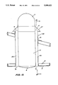
- FIG. 1 is a partial cut-away side view of an installed skylight according to a preferred embodiment
- FIG. 2 is a perspective view of a reflector which is used in the skylight of FIG. 1,
- FIG. 3 is a side view of a reflector which is used in the skylight of FIG. 1,
- FIG. 4 is a top plan view of a reflector which is used in the skylight of FIG. 1,
- FIG. 5 is a plan view of a roof cavity showing support components for the installation of the skylight of FIG. 1,
- FIG. 6 is an exploded plan view of a roof cavity showing support components for the installation of the skylight of FIG. 1,
- FIG. 7 is an inverted plan view of the skylight of FIG. 1,
- FIG. 8 is a plan view of the installed skylight of FIG. 1,
- FIG. 9 is a partial cut-away side view of an installed skylight according to an alternate embodiment
- FIG. 10 is a perspective view of a reflector to be used in the skylight as shown in FIG. 9,
- FIG. 11 is a side view of a reflector to be used in the skylight as shown in FIG. 9,
- FIG. 12 is a top plan view of a reflector to be used in the skylight as shown in FIG. 9,
- FIG. 13 is a plan view of the roof cavity showing support components for the skylight of FIG. 9,
- FIG. 14 is an inverted plan view of the skylight of FIG. 9,
- FIG. 15 is a plan view of the installed skylight of FIG. 9,
- FIG. 16 is a partial cut-away view of an installed skylight with optional venting according to another preferred embodiment
- FIG. 17 is a plan view of the skylight of FIG. 16,
- FIG. 18 is a partial cut-away of an installed skylight with sectional indicator through optional venting of the skylight of FIG. 16,
- FIG. 19 is a cross-sectional view of the venting of FIG. 16,
- FIG. 20 is a partial cut-away view of an installed skylight with optional venting according to an alternate embodiment
- FIG. 21 is a plan view of the installed skylight with optional venting according to an alternate embodiment.
- the skylight 1 of the preferred embodiment as illustrated in FIGS. 1 to 8 comprises a tube 2 which has one hemi-spherical end cap or upper bubble 3 and one dished or "bowter” end cap or diffuser 4 attached thereto.
- the top end cap 3 is made of a clear PERSPEX (Trade Mark) or similar such material and the lower surface has a pattern impressed thereto forming a diffusing effect typical to K15 (Trade Mark).
- the top end cap or upper bubble 3 has a reflector 5 affixed thereto on its inside surface. The reflector 5 reflects the light that would otherwise pass through the sides of the upper bubble 3, into the tube 2 adding to the light incident and transmitted through the tube 2.
- the material of the tube 2 is either metal, fiber or plastics, and has a finish which is a highly reflective polish or coating, as found on "1150 alloy alluminium", electroplating, anodising or metalised plastic film. The coatings applied to all the internal surfaces thereof.
- the combined light passes through the diffuser 4 and is re-directed sideways and upwardly, which is then reflected off walls 16 and ceiling 8 and therefore creates indirect lighting for the room 20.
- the position in the ceiling 8 is determined and a suitable hole 9 is cut out.
- the corresponding roof tiles 10 vertically above the hole 9 are also removed. It is noted at this point that some small portion of battens 13 may need to be removed depending on the positional requirements. The same applies to small and remediable portions of the roof structure.
- the tube 2 is then moved into position between the battens 13, and rested on the ceiling 8.
- Angle brackets 18 are fixed to the ceiling joist 19 with fasteners 21.
- the tube 2 is then lowered into the correct ceiling 8 level (flush with the underside of) which is automatically determined by aligning a bolt 17 with bracket 18 whereby the bolt 17 is affixed.
- This is associated with the embodiment of FIG. 6 whilst in the embodiment of FIG. 5 a plurality of tabs 18 rest on the ceiling 8.
- Flashing 6 is then placed and dressed to the tube 2, and the roof tiles 10 are replaced. It should be noted that the flashing 6 is placed under the roof tile 10 surrounding the tube 2. A hose clamp 11 is then fixed over the tube 2 and the upturn of the flashing 6 and a suitable water resistent sealant is applied therebetween.
- the upper bubble 3 is then affixed, and is secured onto the tube 2 by a hose clamp 11.
- the reflector 5 has already been placed upon the top side of the tube 2 prior to installation.
- the lower bubble or diffuser 4 is then affixed to the lower end of the tube 2 through the hole 9 provided in the ceiling 8.
- the diffuser 4 has a flange 12 or alternatively a dress trim.
- the diffuser 4 can have varying shapes as illustrated in FIGS. 1, 7, 9, 14, 16 and 18 as well as the upper bubble 3 having different shapes as illustrated in FIGS. 1, 7, 9, 16 and 20.
- the present invention eliminates such problems due to the substantially sealed nature of the skylight 1.
- the beforementioned close fit of all the components prevents excess air movement which creates a static column of air within the skylight 1.
- the column of air acts as an insulator combined with the insulating properties of plastics forming the upper bubble 3 and diffuser 4 which prevents heat from entering the room 20.
- the heat that builds up within the skylight 1 is dissipated into the roof cavity via the conductive material of the tube 2.
- the roof cavity would not be as cool as the external temperature prevailing on the outside of the building.
- the conductive material of the tube 2 would absorb some of the heat warming the air column within. As the air column is heated, it therefore follows that the skylight 1 acts as an insulator and maintains a substantial amount of heat within the room 20.
- FIGS. 9 to 15 Another embodiment of the skylight 1 is illustrated in FIGS. 9 to 15. This embodiment illustrated comprises a skylight having a sequare or rectangular cross-section.
- FIGS. 16 to 21 A method of venting the skylight 1 is illustrated in FIGS. 16 to 21.
- dust and pests are prevented from enteringk the skylight 1 by means of a fine metal fly screen 14.
- a venting system 22 has a vent tube 23 painted a substantially black colour which absorbs light.
- the light energy is converted into heat energy and the heat causes the air in the exposedf portion of the vent assembly 24 to the top of the tube 2 to expand.
- the expanded air rises out of the vent assembly 24 causing the displacement of air and the displaced air is replaced by cooler air further down the vent tube 23 which subsequently originates from the room 20, thereby creating a constant airflow from the room 20 through to the outside.
- a rain cover 27 is additionally supplied to the vent tube 23.
- the main benefit of the skylights of the preferred embodiments is that the efficiency of the skylight enables the sky to have a smaller diameter/area than equivalent prior art skylights which provides for economy and speed of installation.
Landscapes
- Engineering & Computer Science (AREA)
- Architecture (AREA)
- Civil Engineering (AREA)
- Structural Engineering (AREA)
- Physics & Mathematics (AREA)
- Electromagnetism (AREA)
- Building Environments (AREA)
Abstract
Description
Claims (12)
Priority Applications (1)
| Application Number | Priority Date | Filing Date | Title |
|---|---|---|---|
| US08/220,001 USRE36496E (en) | 1988-11-22 | 1994-03-29 | Skylight |
Applications Claiming Priority (2)
| Application Number | Priority Date | Filing Date | Title |
|---|---|---|---|
| AUPH858886 | 1986-10-20 | ||
| AU79723/87A AU586359C (en) | 1986-10-20 | 1987-10-13 | A skylight |
Related Child Applications (1)
| Application Number | Title | Priority Date | Filing Date |
|---|---|---|---|
| US08/220,001 Reissue USRE36496E (en) | 1988-11-22 | 1994-03-29 | Skylight |
Publications (1)
| Publication Number | Publication Date |
|---|---|
| US5099622A true US5099622A (en) | 1992-03-31 |
Family
ID=25639341
Family Applications (1)
| Application Number | Title | Priority Date | Filing Date |
|---|---|---|---|
| US07/275,398 Ceased US5099622A (en) | 1986-10-20 | 1988-11-22 | Skylight |
Country Status (1)
| Country | Link |
|---|---|
| US (1) | US5099622A (en) |
Cited By (76)
| Publication number | Priority date | Publication date | Assignee | Title |
|---|---|---|---|---|
| USD364469S (en) | 1994-10-13 | 1995-11-21 | Andersen Corporation | Skylight |
| US5467564A (en) * | 1993-05-28 | 1995-11-21 | Andersen Corporation | Daylight collection and distribution system |
| US5493824A (en) * | 1993-03-29 | 1996-02-27 | Webster; Lee R. | Rotatably mounted skylight having reflectors |
| US5502935A (en) * | 1994-07-18 | 1996-04-02 | Demmer; Albert J. | Roof to ceiling skylight apparatus |
| US5544455A (en) * | 1994-08-12 | 1996-08-13 | Odl, Incorporated | Skylight with modular shaft |
| US5546712A (en) * | 1994-11-03 | 1996-08-20 | Bixby; Joseph A. | System and method of constructing a skylight |
| USD374087S (en) | 1994-11-29 | 1996-09-24 | Andersen Corporation | Skylight |
| US5596848A (en) * | 1993-10-11 | 1997-01-28 | Skydome Industries Limited | Adjustable skylight |
| US5648873A (en) * | 1996-05-30 | 1997-07-15 | Minnesota Mining And Manufacturing Company | Passive solar collector |
| US5655339A (en) * | 1996-08-09 | 1997-08-12 | Odl, Incorporated | Tubular skylight with improved dome |
| US5765317A (en) * | 1997-02-04 | 1998-06-16 | Mast; Daniel Ray | Structurally integrated shelf and soffit configuration |
| US5878539A (en) * | 1997-06-09 | 1999-03-09 | Grubb; Dennis | Method and apparatus for a tubular skylight system |
| US5896713A (en) * | 1997-11-13 | 1999-04-27 | Solatube International, Inc. | Tubular skylight with vertically adjustable tube and improved roof cover seal |
| US5896712A (en) * | 1997-10-24 | 1999-04-27 | Solatube International, Inc. | Light-collecting skylight cover |
| US6035593A (en) * | 1998-07-30 | 2000-03-14 | Solatube International, Inc. | Tubular skylight with snap assembly and expansion spacer |
| US6130781A (en) * | 1998-09-08 | 2000-10-10 | Gauvin; Aime H. | Skylight for day and night illumination |
| US6178707B1 (en) | 1998-08-13 | 2001-01-30 | Daniel Emilio Bengtson | Small skylight with non-tracking solar collector |
| US6256947B1 (en) | 1998-06-04 | 2001-07-10 | Solatube International, Inc. | Method and apparatus for a tubular skylight system |
| US6321493B1 (en) * | 1999-10-07 | 2001-11-27 | Solatube International Inc. | Systems and methods for connecting skylight components |
| US6385922B1 (en) | 1999-06-02 | 2002-05-14 | John A. Mors | Solar light receiving and side emitting system |
| US20030079422A1 (en) * | 2001-10-29 | 2003-05-01 | Energo Project S.R.L. | Tubular skylight for lighting rooms with natural light |
| EP1306606A1 (en) * | 2001-10-29 | 2003-05-02 | Energo Project s.r.l. | Tubular skylight |
| US6813864B2 (en) | 2002-07-01 | 2004-11-09 | Epic Metals Corporation | Decking for receipt of skylights |
| US20050005542A1 (en) * | 2003-07-07 | 2005-01-13 | Prenn Joseph W. | Butterfly valve for skylight |
| US20050005541A1 (en) * | 2001-12-14 | 2005-01-13 | Shane West | Wind directional skylight vent |
| US20050044807A1 (en) * | 2003-09-02 | 2005-03-03 | Rillie David W. | Tubular skylight with dome flashing and protective corrugation |
| US20050044808A1 (en) * | 2003-09-02 | 2005-03-03 | Prenn Joseph W. | Tubular skylight with dome flashing and protective waffle pattern corrugation |
| US20050166490A1 (en) * | 2004-01-09 | 2005-08-04 | Darmer Samuel H. | Skylight with displacement absorber and interlocking telescoping tubes |
| US6990773B2 (en) * | 2001-06-29 | 2006-01-31 | Michael Borges | Flexible reflective skylight tubes |
| WO2006033090A1 (en) | 2004-09-21 | 2006-03-30 | Dublin Institute Of Technology | Multi-aperture light pipe |
| WO2006076914A1 (en) * | 2005-01-24 | 2006-07-27 | Vkr Holding A/S | Roof light system having a ventilation device with improved flexibility |
| US7146768B2 (en) * | 2001-03-30 | 2006-12-12 | Solatube International, Inc. | Skylight tube with reflective film and surface irregularities |
| US7159364B2 (en) * | 1998-07-30 | 2007-01-09 | Solatube International, Inc. | Skylight flashing |
| US20070074468A1 (en) * | 2005-10-03 | 2007-04-05 | Paul Jaster | Tubular skylight dome with variable prism |
| US20070107340A1 (en) * | 2005-11-09 | 2007-05-17 | Smith David L | Rooftop access system |
| US7322156B1 (en) * | 2002-07-12 | 2008-01-29 | Solatube International, Inc. | Skylight domes with reflectors |
| WO2008057453A3 (en) * | 2006-11-08 | 2008-08-07 | Solatube Int Inc | Skylight tube with infrared heat transfer |
| US20090248217A1 (en) * | 2008-03-27 | 2009-10-01 | Orion Energy Systems, Inc. | System and method for reducing peak and off-peak electricity demand by monitoring, controlling and metering high intensity fluorescent lighting in a facility |
| US20090243517A1 (en) * | 2008-03-27 | 2009-10-01 | Orion Energy Systems, Inc. | System and method for controlling lighting |
| US20090315485A1 (en) * | 2007-06-29 | 2009-12-24 | Orion Energy Systems, Inc. | Lighting fixture control systems and methods |
| US20100061088A1 (en) * | 2007-06-29 | 2010-03-11 | Orion Energy Systems, Inc. | Lighting device |
| US20100309556A1 (en) * | 2009-06-04 | 2010-12-09 | Solatube International, Inc. | Skylight collimator with multiple stages |
| US20110044041A1 (en) * | 2009-08-20 | 2011-02-24 | Paul August Jaster | Daylighting devices and methods with auxiliary lighting fixtures |
| US20110060701A1 (en) * | 2009-09-04 | 2011-03-10 | Orion Energy Systems, Inc. | Outdoor fluorescent lighting fixtures and related systems and methods |
| US20110141570A1 (en) * | 2009-12-11 | 2011-06-16 | David Windsor Rillie | Direct and indirect light diffusing devices and methods |
| US8371078B2 (en) | 2009-06-25 | 2013-02-12 | Solatube International | Sunlight collection system and apparatus |
| US8445826B2 (en) | 2007-06-29 | 2013-05-21 | Orion Energy Systems, Inc. | Outdoor lighting systems and methods for wireless network communications |
| US8476565B2 (en) | 2007-06-29 | 2013-07-02 | Orion Energy Systems, Inc. | Outdoor lighting fixtures control systems and methods |
| JP2013182668A (en) * | 2012-02-29 | 2013-09-12 | Ryoko:Kk | Sunlight daylighting device |
| US8568011B2 (en) | 2009-08-20 | 2013-10-29 | Solatube International, Inc. | Daylighting devices with auxiliary lighting system and light turning features |
| US8586902B2 (en) | 2007-06-29 | 2013-11-19 | Orion Energy Systems, Inc. | Outdoor lighting fixture and camera systems |
| US8601757B2 (en) | 2010-05-27 | 2013-12-10 | Solatube International, Inc. | Thermally insulating fenestration devices and methods |
| US8729446B2 (en) | 2007-06-29 | 2014-05-20 | Orion Energy Systems, Inc. | Outdoor lighting fixtures for controlling traffic lights |
| US8745938B2 (en) | 2012-07-27 | 2014-06-10 | Replex Mirror Company | Skylight with improved low angle light capture |
| US8797652B2 (en) | 2012-01-20 | 2014-08-05 | Vkr Holding A/S | Skylight sunlight redirector |
| US8837048B2 (en) | 2011-11-30 | 2014-09-16 | Solatube International, Inc. | Daylight collection systems and methods |
| US8884203B2 (en) | 2007-05-03 | 2014-11-11 | Orion Energy Systems, Inc. | Lighting systems and methods for displacing energy consumption using natural lighting fixtures |
| US8896924B2 (en) | 2012-05-04 | 2014-11-25 | Abl Ip Holding, Llc | Tubular daylighting system |
| US8982467B2 (en) | 2012-12-11 | 2015-03-17 | Solatube International, Inc. | High aspect ratio daylight collectors |
| US20150128516A1 (en) * | 2011-07-11 | 2015-05-14 | Robby Lewis Valencia | Dual pitched, square, low profile, galvanized metal roof flashing for rigid tubular daylighting systems. |
| WO2016005964A1 (en) | 2014-07-09 | 2016-01-14 | Solight Ltd. | System for collecting electromagnetic radiation from a moving source |
| US9322178B2 (en) | 2013-12-15 | 2016-04-26 | Vkr Holdings A/S | Skylight with sunlight pivot |
| US9482399B2 (en) | 2013-03-15 | 2016-11-01 | Vkr Holding A/S | Light tube kit for skylight |
| US9797141B2 (en) | 2014-06-04 | 2017-10-24 | Abl Ip Holding Llc | Light fixture with photosensor-activated adjustable louver assembly |
| US9816676B2 (en) | 2015-03-18 | 2017-11-14 | Solatube International, Inc. | Daylight collectors with diffuse and direct light collection |
| US9816675B2 (en) | 2015-03-18 | 2017-11-14 | Solatube International, Inc. | Daylight collectors with diffuse and direct light collection |
| US9897289B2 (en) | 2014-06-04 | 2018-02-20 | Abl Ip Holdings Llc | Light fixture with photosensor-activated adjustable louver assembly and color temperature control |
| US9921397B2 (en) | 2012-12-11 | 2018-03-20 | Solatube International, Inc. | Daylight collectors with thermal control |
| US10294670B1 (en) * | 2015-11-11 | 2019-05-21 | MGM Products, Inc. | Architectural screen roof curbs |
| US10874006B1 (en) | 2019-03-08 | 2020-12-22 | Abl Ip Holding Llc | Lighting fixture controller for controlling color temperature and intensity |
| US11168480B2 (en) | 2019-02-21 | 2021-11-09 | Solatube International, Inc. | Skylight dimmer |
| US11261604B1 (en) * | 2016-11-10 | 2022-03-01 | MGM Products, Inc. | Cantilevered objects |
| IT202100027995A1 (en) * | 2021-11-03 | 2023-05-03 | Solarspot Int S R L | TUBULAR SKYLIGHT |
| US11859387B1 (en) * | 2015-11-11 | 2024-01-02 | MGM Products, Inc. | Roof curb with cantilevered objects |
| US12404676B2 (en) | 2022-11-04 | 2025-09-02 | Douglas Austin | Low-profile skylight device |
| US12577782B1 (en) | 2022-01-25 | 2026-03-17 | Michael Brent Powers | Safety cages for protecting tubular skylights |
Citations (4)
| Publication number | Priority date | Publication date | Assignee | Title |
|---|---|---|---|---|
| US4280480A (en) * | 1980-03-17 | 1981-07-28 | Raposo Sulpicio B | Solar heating plant |
| US4339900A (en) * | 1980-09-29 | 1982-07-20 | Freeman William T | Sky-light structure having a flexible-tube shaft |
| US4620771A (en) * | 1984-09-06 | 1986-11-04 | So-Luminaire Systems Corp. | Combined solar tracking reflector and photovoltaic panel |
| US4733505A (en) * | 1985-10-22 | 1988-03-29 | James Van Dame | Energy-efficient skylight structure |
-
1988
- 1988-11-22 US US07/275,398 patent/US5099622A/en not_active Ceased
Patent Citations (4)
| Publication number | Priority date | Publication date | Assignee | Title |
|---|---|---|---|---|
| US4280480A (en) * | 1980-03-17 | 1981-07-28 | Raposo Sulpicio B | Solar heating plant |
| US4339900A (en) * | 1980-09-29 | 1982-07-20 | Freeman William T | Sky-light structure having a flexible-tube shaft |
| US4620771A (en) * | 1984-09-06 | 1986-11-04 | So-Luminaire Systems Corp. | Combined solar tracking reflector and photovoltaic panel |
| US4733505A (en) * | 1985-10-22 | 1988-03-29 | James Van Dame | Energy-efficient skylight structure |
Cited By (125)
| Publication number | Priority date | Publication date | Assignee | Title |
|---|---|---|---|---|
| US5493824A (en) * | 1993-03-29 | 1996-02-27 | Webster; Lee R. | Rotatably mounted skylight having reflectors |
| US5467564A (en) * | 1993-05-28 | 1995-11-21 | Andersen Corporation | Daylight collection and distribution system |
| US5596848A (en) * | 1993-10-11 | 1997-01-28 | Skydome Industries Limited | Adjustable skylight |
| US5502935A (en) * | 1994-07-18 | 1996-04-02 | Demmer; Albert J. | Roof to ceiling skylight apparatus |
| US5544455A (en) * | 1994-08-12 | 1996-08-13 | Odl, Incorporated | Skylight with modular shaft |
| USD364469S (en) | 1994-10-13 | 1995-11-21 | Andersen Corporation | Skylight |
| US5546712A (en) * | 1994-11-03 | 1996-08-20 | Bixby; Joseph A. | System and method of constructing a skylight |
| USD374087S (en) | 1994-11-29 | 1996-09-24 | Andersen Corporation | Skylight |
| US5648873A (en) * | 1996-05-30 | 1997-07-15 | Minnesota Mining And Manufacturing Company | Passive solar collector |
| US5655339A (en) * | 1996-08-09 | 1997-08-12 | Odl, Incorporated | Tubular skylight with improved dome |
| WO1998006914A1 (en) * | 1996-08-09 | 1998-02-19 | Odl, Incorporated | Tubular skylight with improved dome |
| USRE38217E1 (en) | 1996-08-09 | 2003-08-19 | Odl, Incorporated | Tubular skylight with improved dome |
| US5765317A (en) * | 1997-02-04 | 1998-06-16 | Mast; Daniel Ray | Structurally integrated shelf and soffit configuration |
| US5878539A (en) * | 1997-06-09 | 1999-03-09 | Grubb; Dennis | Method and apparatus for a tubular skylight system |
| US5896712A (en) * | 1997-10-24 | 1999-04-27 | Solatube International, Inc. | Light-collecting skylight cover |
| US5896713A (en) * | 1997-11-13 | 1999-04-27 | Solatube International, Inc. | Tubular skylight with vertically adjustable tube and improved roof cover seal |
| US6256947B1 (en) | 1998-06-04 | 2001-07-10 | Solatube International, Inc. | Method and apparatus for a tubular skylight system |
| US6035593A (en) * | 1998-07-30 | 2000-03-14 | Solatube International, Inc. | Tubular skylight with snap assembly and expansion spacer |
| US7159364B2 (en) * | 1998-07-30 | 2007-01-09 | Solatube International, Inc. | Skylight flashing |
| US6178707B1 (en) | 1998-08-13 | 2001-01-30 | Daniel Emilio Bengtson | Small skylight with non-tracking solar collector |
| US6130781A (en) * | 1998-09-08 | 2000-10-10 | Gauvin; Aime H. | Skylight for day and night illumination |
| US6385922B1 (en) | 1999-06-02 | 2002-05-14 | John A. Mors | Solar light receiving and side emitting system |
| US6321493B1 (en) * | 1999-10-07 | 2001-11-27 | Solatube International Inc. | Systems and methods for connecting skylight components |
| US6363668B2 (en) * | 1999-10-07 | 2002-04-02 | Solatube International, Inc. | Systems and methods for connecting skylight components |
| US6415563B2 (en) * | 1999-10-07 | 2002-07-09 | Solatube International, Inc. | Systems and methods for connecting skylight components |
| US7146768B2 (en) * | 2001-03-30 | 2006-12-12 | Solatube International, Inc. | Skylight tube with reflective film and surface irregularities |
| US6990773B2 (en) * | 2001-06-29 | 2006-01-31 | Michael Borges | Flexible reflective skylight tubes |
| US7185464B2 (en) | 2001-10-29 | 2007-03-06 | Gennaro Bracale | Tubular skylight for lighting rooms with natural light |
| US20030079422A1 (en) * | 2001-10-29 | 2003-05-01 | Energo Project S.R.L. | Tubular skylight for lighting rooms with natural light |
| EP1306606A1 (en) * | 2001-10-29 | 2003-05-02 | Energo Project s.r.l. | Tubular skylight |
| US20050005541A1 (en) * | 2001-12-14 | 2005-01-13 | Shane West | Wind directional skylight vent |
| US7487620B2 (en) * | 2001-12-14 | 2009-02-10 | Shane West | Wind directional skylight vent |
| US6813864B2 (en) | 2002-07-01 | 2004-11-09 | Epic Metals Corporation | Decking for receipt of skylights |
| US7322156B1 (en) * | 2002-07-12 | 2008-01-29 | Solatube International, Inc. | Skylight domes with reflectors |
| US7082726B2 (en) * | 2003-07-07 | 2006-08-01 | Solatube International, Inc. | Butterfly valve for skylight |
| US20050005542A1 (en) * | 2003-07-07 | 2005-01-13 | Prenn Joseph W. | Butterfly valve for skylight |
| US20050188629A1 (en) * | 2003-09-02 | 2005-09-01 | Solatube International, Inc. | Tubular skylight with dome flashing and protective corrugation |
| US20050044808A1 (en) * | 2003-09-02 | 2005-03-03 | Prenn Joseph W. | Tubular skylight with dome flashing and protective waffle pattern corrugation |
| US7040061B2 (en) | 2003-09-02 | 2006-05-09 | Solatube International, Inc. | Tubular skylight with dome flashing and protective corrugation |
| US20050044807A1 (en) * | 2003-09-02 | 2005-03-03 | Rillie David W. | Tubular skylight with dome flashing and protective corrugation |
| US20050252111A1 (en) * | 2003-09-02 | 2005-11-17 | Solatube International | Tubular skylight with dome flashing and protective waffle pattern corrugation |
| US7168211B2 (en) * | 2003-09-02 | 2007-01-30 | Solatube International, Inc. | Tubular skylight with dome flashing and protective waffle pattern corrugation |
| US8555571B2 (en) | 2004-01-09 | 2013-10-15 | Vkr Holding A/S | Skylight with displacement absorber and interlocking telescoping tubes |
| US20050166490A1 (en) * | 2004-01-09 | 2005-08-04 | Darmer Samuel H. | Skylight with displacement absorber and interlocking telescoping tubes |
| WO2006033090A1 (en) | 2004-09-21 | 2006-03-30 | Dublin Institute Of Technology | Multi-aperture light pipe |
| WO2006076914A1 (en) * | 2005-01-24 | 2006-07-27 | Vkr Holding A/S | Roof light system having a ventilation device with improved flexibility |
| US20080207108A1 (en) * | 2005-01-24 | 2008-08-28 | Brent Moller | Roof Light System Having a Ventilation Device with Improved Flexibility |
| US8292706B2 (en) | 2005-01-24 | 2012-10-23 | Vkr Holding A/S | Roof light system having a ventilation device with improved flexibility |
| US20070074468A1 (en) * | 2005-10-03 | 2007-04-05 | Paul Jaster | Tubular skylight dome with variable prism |
| US7546709B2 (en) | 2005-10-03 | 2009-06-16 | Solatube International, Inc. | Tubular skylight dome with variable prism |
| US20070107340A1 (en) * | 2005-11-09 | 2007-05-17 | Smith David L | Rooftop access system |
| US8307590B2 (en) * | 2005-11-09 | 2012-11-13 | REACH Manufacturing, Inc. | Rooftop access system |
| AU2007317918B2 (en) * | 2006-11-08 | 2012-07-12 | Solatube International, Inc. | Skylight tube with infrared heat transfer |
| US7954281B2 (en) | 2006-11-08 | 2011-06-07 | Solatube International, Inc. | Skylight tube with infrared heat transfer |
| WO2008057453A3 (en) * | 2006-11-08 | 2008-08-07 | Solatube Int Inc | Skylight tube with infrared heat transfer |
| CN101553633B (en) * | 2006-11-08 | 2013-05-01 | 索乐图国际公司 | Skylight tube with infrared heat transfer |
| US9521726B2 (en) | 2007-05-03 | 2016-12-13 | Orion Energy Systems, Inc. | Lighting systems and methods for displacing energy consumption using natural lighting fixtures |
| US8884203B2 (en) | 2007-05-03 | 2014-11-11 | Orion Energy Systems, Inc. | Lighting systems and methods for displacing energy consumption using natural lighting fixtures |
| US10187557B2 (en) | 2007-06-29 | 2019-01-22 | Orion Energy Systems, Inc. | Outdoor lighting fixture and camera systems |
| US8729446B2 (en) | 2007-06-29 | 2014-05-20 | Orion Energy Systems, Inc. | Outdoor lighting fixtures for controlling traffic lights |
| US11432390B2 (en) | 2007-06-29 | 2022-08-30 | Orion Energy Systems, Inc. | Outdoor lighting fixtures control systems and methods |
| US11202355B2 (en) | 2007-06-29 | 2021-12-14 | Orion Energy Systems, Inc. | Outdoor lighting fixture and camera systems |
| US20090315485A1 (en) * | 2007-06-29 | 2009-12-24 | Orion Energy Systems, Inc. | Lighting fixture control systems and methods |
| US11026302B2 (en) | 2007-06-29 | 2021-06-01 | Orion Energy Systems, Inc. | Outdoor lighting fixtures control systems and methods |
| US10694594B2 (en) | 2007-06-29 | 2020-06-23 | Orion Energy Systems, Inc. | Lighting fixture control systems and methods |
| US10694605B2 (en) | 2007-06-29 | 2020-06-23 | Orion Energy Systems, Inc. | Outdoor lighting fixtures control systems and methods |
| US10206265B2 (en) | 2007-06-29 | 2019-02-12 | Orion Energy Systems, Inc. | Outdoor lighting fixtures control systems and methods |
| US8376600B2 (en) | 2007-06-29 | 2013-02-19 | Orion Energy Systems, Inc. | Lighting device |
| US20100061088A1 (en) * | 2007-06-29 | 2010-03-11 | Orion Energy Systems, Inc. | Lighting device |
| US10098213B2 (en) | 2007-06-29 | 2018-10-09 | Orion Energy Systems, Inc. | Lighting fixture control systems and methods |
| US8445826B2 (en) | 2007-06-29 | 2013-05-21 | Orion Energy Systems, Inc. | Outdoor lighting systems and methods for wireless network communications |
| US8450670B2 (en) | 2007-06-29 | 2013-05-28 | Orion Energy Systems, Inc. | Lighting fixture control systems and methods |
| US8476565B2 (en) | 2007-06-29 | 2013-07-02 | Orion Energy Systems, Inc. | Outdoor lighting fixtures control systems and methods |
| US8921751B2 (en) | 2007-06-29 | 2014-12-30 | Orion Energy Systems, Inc. | Outdoor lighting fixtures control systems and methods |
| US8779340B2 (en) | 2007-06-29 | 2014-07-15 | Orion Energy Systems, Inc. | Lighting fixture control systems and methods |
| US9146012B2 (en) | 2007-06-29 | 2015-09-29 | Orion Energy Systems, Inc. | Lighting device |
| US8586902B2 (en) | 2007-06-29 | 2013-11-19 | Orion Energy Systems, Inc. | Outdoor lighting fixture and camera systems |
| US9215780B2 (en) | 2008-03-27 | 2015-12-15 | Orion Energy Systems, Inc. | System and method for reducing peak and off-peak electricity demand by monitoring, controlling and metering lighting in a facility |
| US10334704B2 (en) | 2008-03-27 | 2019-06-25 | Orion Energy Systems, Inc. | System and method for reducing peak and off-peak electricity demand by monitoring, controlling and metering lighting in a facility |
| US9504133B2 (en) | 2008-03-27 | 2016-11-22 | Orion Energy Systems, Inc. | System and method for controlling lighting |
| US9351381B2 (en) | 2008-03-27 | 2016-05-24 | Orion Energy Systems, Inc. | System and method for controlling lighting |
| US8406937B2 (en) | 2008-03-27 | 2013-03-26 | Orion Energy Systems, Inc. | System and method for reducing peak and off-peak electricity demand by monitoring, controlling and metering high intensity fluorescent lighting in a facility |
| US8666559B2 (en) | 2008-03-27 | 2014-03-04 | Orion Energy Systems, Inc. | System and method for reducing peak and off-peak electricity demand by monitoring, controlling and metering high intensity fluorescent lighting in a facility |
| US20090243517A1 (en) * | 2008-03-27 | 2009-10-01 | Orion Energy Systems, Inc. | System and method for controlling lighting |
| US8344665B2 (en) | 2008-03-27 | 2013-01-01 | Orion Energy Systems, Inc. | System and method for controlling lighting |
| US20090248217A1 (en) * | 2008-03-27 | 2009-10-01 | Orion Energy Systems, Inc. | System and method for reducing peak and off-peak electricity demand by monitoring, controlling and metering high intensity fluorescent lighting in a facility |
| US20100309556A1 (en) * | 2009-06-04 | 2010-12-09 | Solatube International, Inc. | Skylight collimator with multiple stages |
| US7957065B2 (en) | 2009-06-04 | 2011-06-07 | Solatube International, Inc. | Skylight collimator with multiple stages |
| US8371078B2 (en) | 2009-06-25 | 2013-02-12 | Solatube International | Sunlight collection system and apparatus |
| US8083363B2 (en) | 2009-08-20 | 2011-12-27 | Solatube International, Inc. | Daylighting devices and methods with auxiliary lighting fixtures |
| US8568011B2 (en) | 2009-08-20 | 2013-10-29 | Solatube International, Inc. | Daylighting devices with auxiliary lighting system and light turning features |
| US20110044041A1 (en) * | 2009-08-20 | 2011-02-24 | Paul August Jaster | Daylighting devices and methods with auxiliary lighting fixtures |
| US20110060701A1 (en) * | 2009-09-04 | 2011-03-10 | Orion Energy Systems, Inc. | Outdoor fluorescent lighting fixtures and related systems and methods |
| US9523485B2 (en) | 2009-09-04 | 2016-12-20 | Orion Energy Systems, Inc. | Outdoor lighting fixtures and related systems and methods |
| US9951933B2 (en) | 2009-09-04 | 2018-04-24 | Orion Energy Systems, Inc. | Outdoor lighting fixtures and related systems and methods |
| US8866582B2 (en) | 2009-09-04 | 2014-10-21 | Orion Energy Systems, Inc. | Outdoor fluorescent lighting fixtures and related systems and methods |
| US20110141570A1 (en) * | 2009-12-11 | 2011-06-16 | David Windsor Rillie | Direct and indirect light diffusing devices and methods |
| US8098433B2 (en) | 2009-12-11 | 2012-01-17 | Solatube International, Inc. | Direct and indirect light diffusing devices and methods |
| US8601757B2 (en) | 2010-05-27 | 2013-12-10 | Solatube International, Inc. | Thermally insulating fenestration devices and methods |
| US20150128516A1 (en) * | 2011-07-11 | 2015-05-14 | Robby Lewis Valencia | Dual pitched, square, low profile, galvanized metal roof flashing for rigid tubular daylighting systems. |
| US8837048B2 (en) | 2011-11-30 | 2014-09-16 | Solatube International, Inc. | Daylight collection systems and methods |
| US8797652B2 (en) | 2012-01-20 | 2014-08-05 | Vkr Holding A/S | Skylight sunlight redirector |
| JP2013182668A (en) * | 2012-02-29 | 2013-09-12 | Ryoko:Kk | Sunlight daylighting device |
| US8896924B2 (en) | 2012-05-04 | 2014-11-25 | Abl Ip Holding, Llc | Tubular daylighting system |
| US8745938B2 (en) | 2012-07-27 | 2014-06-10 | Replex Mirror Company | Skylight with improved low angle light capture |
| US9291321B2 (en) | 2012-12-11 | 2016-03-22 | Solatube International, Inc. | Devices and methods for collecting daylight in clear and cloudy weather conditions |
| US8982467B2 (en) | 2012-12-11 | 2015-03-17 | Solatube International, Inc. | High aspect ratio daylight collectors |
| US9921397B2 (en) | 2012-12-11 | 2018-03-20 | Solatube International, Inc. | Daylight collectors with thermal control |
| US9482399B2 (en) | 2013-03-15 | 2016-11-01 | Vkr Holding A/S | Light tube kit for skylight |
| US9322178B2 (en) | 2013-12-15 | 2016-04-26 | Vkr Holdings A/S | Skylight with sunlight pivot |
| US9897289B2 (en) | 2014-06-04 | 2018-02-20 | Abl Ip Holdings Llc | Light fixture with photosensor-activated adjustable louver assembly and color temperature control |
| US9797141B2 (en) | 2014-06-04 | 2017-10-24 | Abl Ip Holding Llc | Light fixture with photosensor-activated adjustable louver assembly |
| WO2016005964A1 (en) | 2014-07-09 | 2016-01-14 | Solight Ltd. | System for collecting electromagnetic radiation from a moving source |
| US9816675B2 (en) | 2015-03-18 | 2017-11-14 | Solatube International, Inc. | Daylight collectors with diffuse and direct light collection |
| US9816676B2 (en) | 2015-03-18 | 2017-11-14 | Solatube International, Inc. | Daylight collectors with diffuse and direct light collection |
| US11859387B1 (en) * | 2015-11-11 | 2024-01-02 | MGM Products, Inc. | Roof curb with cantilevered objects |
| US10294670B1 (en) * | 2015-11-11 | 2019-05-21 | MGM Products, Inc. | Architectural screen roof curbs |
| US11261604B1 (en) * | 2016-11-10 | 2022-03-01 | MGM Products, Inc. | Cantilevered objects |
| US11168480B2 (en) | 2019-02-21 | 2021-11-09 | Solatube International, Inc. | Skylight dimmer |
| US11585093B2 (en) | 2019-02-21 | 2023-02-21 | Solatube International, Inc. | Skylight dimmer |
| US11470698B2 (en) | 2019-03-08 | 2022-10-11 | Abl Ip Holding Llc | Lighting fixture controller for controlling color temperature and intensity |
| US10874006B1 (en) | 2019-03-08 | 2020-12-22 | Abl Ip Holding Llc | Lighting fixture controller for controlling color temperature and intensity |
| IT202100027995A1 (en) * | 2021-11-03 | 2023-05-03 | Solarspot Int S R L | TUBULAR SKYLIGHT |
| US12577782B1 (en) | 2022-01-25 | 2026-03-17 | Michael Brent Powers | Safety cages for protecting tubular skylights |
| US12404676B2 (en) | 2022-11-04 | 2025-09-02 | Douglas Austin | Low-profile skylight device |
Also Published As
| Publication number | Publication date |
|---|---|
| AU586359B2 (en) | 1989-07-06 |
| AU7972387A (en) | 1988-04-21 |
Similar Documents
| Publication | Publication Date | Title |
|---|---|---|
| US5099622A (en) | Skylight | |
| USRE36496E (en) | Skylight | |
| US4776141A (en) | Skylights | |
| US6052956A (en) | Skylight assembly | |
| US5561952A (en) | Combination skylight/static ventilator | |
| US5806255A (en) | Skylight and method to install | |
| AU726665B2 (en) | Gable end roof ventilator | |
| US4598505A (en) | Flashing member | |
| CA1334328E (en) | Skylight | |
| US4414784A (en) | Greenhouse structure | |
| US20050081462A1 (en) | Skylight kit and method | |
| US7127855B1 (en) | Temperature responsive roof vent | |
| GB2236792A (en) | Extruded glazing bar system on wooden support structure | |
| JPS587841Y2 (en) | building | |
| JP3089182B2 (en) | Attic ventilation structure | |
| JPS6320728Y2 (en) | ||
| JPS6320734Y2 (en) | ||
| JPS58123962A (en) | Skylight structure | |
| JPH108658A (en) | Skylight connection body and skylight connection structure using the same | |
| JP2557793Y2 (en) | Mounting structure of flat lighting tile | |
| JPH0420467B2 (en) | ||
| JPS6140818Y2 (en) | ||
| JPS631685Y2 (en) | ||
| JPH07180314A (en) | Building roof ridge structure | |
| JPS6243052Y2 (en) |
Legal Events
| Date | Code | Title | Description |
|---|---|---|---|
| AS | Assignment |
Owner name: CONTINUUM DEVELOPMENTS PTY LIMITED, AUSTRALIA Free format text: ASSIGNMENT OF ASSIGNORS INTEREST.;ASSIGNOR:SUTTON, STEVEN M.;REEL/FRAME:005238/0821 Effective date: 19890816 |
|
| STCF | Information on status: patent grant |
Free format text: PATENTED CASE |
|
| RF | Reissue application filed |
Effective date: 19940329 |
|
| FEPP | Fee payment procedure |
Free format text: PAYOR NUMBER ASSIGNED (ORIGINAL EVENT CODE: ASPN); ENTITY STATUS OF PATENT OWNER: SMALL ENTITY |
|
| FPAY | Fee payment |
Year of fee payment: 4 |
|
| REMI | Maintenance fee reminder mailed | ||
| AS | Assignment |
Owner name: PRAESIDIAN II SPV 1, LP, NEW YORK Free format text: GRANT OF SECURITY INTEREST;ASSIGNOR:SOLATUBE INTERNATIONAL, INC.;REEL/FRAME:019597/0969 Effective date: 20070725 |
|
| AS | Assignment |
Owner name: SOLATUBE INTERNATIONAL, INC., CALIFORNIA Free format text: RELEASE BY SECURED PARTY;ASSIGNOR:PRAESIDIAN II SPV 1, LP;REEL/FRAME:057917/0884 Effective date: 20211025 |