EP2778434A2 - Schwingungsunterdrückungsvorrichtung für eine Strahlpumpe, Strahlpumpe und Schwingungsunterdrückungsverfahren dafür - Google Patents
Schwingungsunterdrückungsvorrichtung für eine Strahlpumpe, Strahlpumpe und Schwingungsunterdrückungsverfahren dafür Download PDFInfo
- Publication number
- EP2778434A2 EP2778434A2 EP14159972.0A EP14159972A EP2778434A2 EP 2778434 A2 EP2778434 A2 EP 2778434A2 EP 14159972 A EP14159972 A EP 14159972A EP 2778434 A2 EP2778434 A2 EP 2778434A2
- Authority
- EP
- European Patent Office
- Prior art keywords
- flow channel
- diffuser
- vibration suppressing
- clearance flow
- jet pump
- Prior art date
- Legal status (The legal status is an assumption and is not a legal conclusion. Google has not performed a legal analysis and makes no representation as to the accuracy of the status listed.)
- Withdrawn
Links
- 238000000034 method Methods 0.000 title claims description 9
- XLYOFNOQVPJJNP-UHFFFAOYSA-N water Substances O XLYOFNOQVPJJNP-UHFFFAOYSA-N 0.000 claims abstract description 20
- 238000009835 boiling Methods 0.000 claims abstract description 16
- 239000000498 cooling water Substances 0.000 claims abstract description 7
- 238000013016 damping Methods 0.000 claims description 56
- 239000012530 fluid Substances 0.000 claims description 52
- 239000000654 additive Substances 0.000 claims description 24
- 230000000996 additive effect Effects 0.000 claims description 24
- 239000002184 metal Substances 0.000 claims description 5
- 230000013011 mating Effects 0.000 claims 1
- 230000004048 modification Effects 0.000 description 16
- 238000012986 modification Methods 0.000 description 16
- 230000001629 suppression Effects 0.000 description 16
- 238000003780 insertion Methods 0.000 description 14
- 230000037431 insertion Effects 0.000 description 14
- 230000000694 effects Effects 0.000 description 12
- 230000008878 coupling Effects 0.000 description 9
- 238000010168 coupling process Methods 0.000 description 9
- 238000005859 coupling reaction Methods 0.000 description 9
- 238000009434 installation Methods 0.000 description 8
- 238000012546 transfer Methods 0.000 description 6
- 239000002826 coolant Substances 0.000 description 5
- 238000006073 displacement reaction Methods 0.000 description 5
- 239000011159 matrix material Substances 0.000 description 5
- 239000013256 coordination polymer Substances 0.000 description 4
- 230000007423 decrease Effects 0.000 description 4
- 230000008859 change Effects 0.000 description 3
- 238000010586 diagram Methods 0.000 description 3
- 238000002474 experimental method Methods 0.000 description 3
- 239000007788 liquid Substances 0.000 description 2
- 241000009298 Trigla lyra Species 0.000 description 1
- 230000001133 acceleration Effects 0.000 description 1
- 230000009471 action Effects 0.000 description 1
- 230000004323 axial length Effects 0.000 description 1
- 238000005253 cladding Methods 0.000 description 1
- 230000010354 integration Effects 0.000 description 1
- 230000010355 oscillation Effects 0.000 description 1
- 238000005086 pumping Methods 0.000 description 1
- 230000009467 reduction Effects 0.000 description 1
- 230000008961 swelling Effects 0.000 description 1
Images







Classifications
-
- F—MECHANICAL ENGINEERING; LIGHTING; HEATING; WEAPONS; BLASTING
- F04—POSITIVE - DISPLACEMENT MACHINES FOR LIQUIDS; PUMPS FOR LIQUIDS OR ELASTIC FLUIDS
- F04F—PUMPING OF FLUID BY DIRECT CONTACT OF ANOTHER FLUID OR BY USING INERTIA OF FLUID TO BE PUMPED; SIPHONS
- F04F5/00—Jet pumps, i.e. devices in which flow is induced by pressure drop caused by velocity of another fluid flow
- F04F5/02—Jet pumps, i.e. devices in which flow is induced by pressure drop caused by velocity of another fluid flow the inducing fluid being liquid
- F04F5/10—Jet pumps, i.e. devices in which flow is induced by pressure drop caused by velocity of another fluid flow the inducing fluid being liquid displacing liquids, e.g. containing solids, or liquids and elastic fluids
-
- F—MECHANICAL ENGINEERING; LIGHTING; HEATING; WEAPONS; BLASTING
- F04—POSITIVE - DISPLACEMENT MACHINES FOR LIQUIDS; PUMPS FOR LIQUIDS OR ELASTIC FLUIDS
- F04F—PUMPING OF FLUID BY DIRECT CONTACT OF ANOTHER FLUID OR BY USING INERTIA OF FLUID TO BE PUMPED; SIPHONS
- F04F5/00—Jet pumps, i.e. devices in which flow is induced by pressure drop caused by velocity of another fluid flow
- F04F5/44—Component parts, details, or accessories not provided for in, or of interest apart from, groups F04F5/02 - F04F5/42
- F04F5/46—Arrangements of nozzles
-
- F—MECHANICAL ENGINEERING; LIGHTING; HEATING; WEAPONS; BLASTING
- F04—POSITIVE - DISPLACEMENT MACHINES FOR LIQUIDS; PUMPS FOR LIQUIDS OR ELASTIC FLUIDS
- F04F—PUMPING OF FLUID BY DIRECT CONTACT OF ANOTHER FLUID OR BY USING INERTIA OF FLUID TO BE PUMPED; SIPHONS
- F04F5/00—Jet pumps, i.e. devices in which flow is induced by pressure drop caused by velocity of another fluid flow
- F04F5/44—Component parts, details, or accessories not provided for in, or of interest apart from, groups F04F5/02 - F04F5/42
- F04F5/46—Arrangements of nozzles
- F04F5/463—Arrangements of nozzles with provisions for mixing
-
- F—MECHANICAL ENGINEERING; LIGHTING; HEATING; WEAPONS; BLASTING
- F04—POSITIVE - DISPLACEMENT MACHINES FOR LIQUIDS; PUMPS FOR LIQUIDS OR ELASTIC FLUIDS
- F04F—PUMPING OF FLUID BY DIRECT CONTACT OF ANOTHER FLUID OR BY USING INERTIA OF FLUID TO BE PUMPED; SIPHONS
- F04F5/00—Jet pumps, i.e. devices in which flow is induced by pressure drop caused by velocity of another fluid flow
- F04F5/44—Component parts, details, or accessories not provided for in, or of interest apart from, groups F04F5/02 - F04F5/42
- F04F5/46—Arrangements of nozzles
- F04F5/464—Arrangements of nozzles with inversion of the direction of flow
-
- F—MECHANICAL ENGINEERING; LIGHTING; HEATING; WEAPONS; BLASTING
- F04—POSITIVE - DISPLACEMENT MACHINES FOR LIQUIDS; PUMPS FOR LIQUIDS OR ELASTIC FLUIDS
- F04F—PUMPING OF FLUID BY DIRECT CONTACT OF ANOTHER FLUID OR BY USING INERTIA OF FLUID TO BE PUMPED; SIPHONS
- F04F5/00—Jet pumps, i.e. devices in which flow is induced by pressure drop caused by velocity of another fluid flow
- F04F5/54—Installations characterised by use of jet pumps, e.g. combinations of two or more jet pumps of different type
-
- G—PHYSICS
- G21—NUCLEAR PHYSICS; NUCLEAR ENGINEERING
- G21C—NUCLEAR REACTORS
- G21C15/00—Cooling arrangements within the pressure vessel containing the core; Selection of specific coolants
- G21C15/24—Promoting flow of the coolant
- G21C15/243—Promoting flow of the coolant for liquids
- G21C15/25—Promoting flow of the coolant for liquids using jet pumps
-
- Y—GENERAL TAGGING OF NEW TECHNOLOGICAL DEVELOPMENTS; GENERAL TAGGING OF CROSS-SECTIONAL TECHNOLOGIES SPANNING OVER SEVERAL SECTIONS OF THE IPC; TECHNICAL SUBJECTS COVERED BY FORMER USPC CROSS-REFERENCE ART COLLECTIONS [XRACs] AND DIGESTS
- Y02—TECHNOLOGIES OR APPLICATIONS FOR MITIGATION OR ADAPTATION AGAINST CLIMATE CHANGE
- Y02E—REDUCTION OF GREENHOUSE GAS [GHG] EMISSIONS, RELATED TO ENERGY GENERATION, TRANSMISSION OR DISTRIBUTION
- Y02E30/00—Energy generation of nuclear origin
- Y02E30/30—Nuclear fission reactors
Definitions
- Embodiments of the present invention relate to a vibration suppressing device for a jet pump that suppresses a self-excited vibration caused by a clearance flow in a slip joint, the jet pump and a vibration suppressing method for the jet pump.
- a boiling water reactor incorporates a plurality of jet pumps disposed at intervals along the circumference in an annular space between a reactor pressure vessel and a reactor core shroud inside the reactor pressure vessel.
- the jet pump is a component of a recirculation system used for adjusting the core flow rate and is essentially composed of a riser pipe, an elbow portion, an inlet mixer pipe and a diffuser.
- the riser pipe is fixed by a riser brace welded to the wall of the reactor pressure vessel, and the diffuser is fixed to an annular pump deck at the lower end thereof.
- the inlet mixer pipe is supported by a riser bracket fixed to the riser pipe with a wedge and a set screw and coupled to the upper portion of the diffuser at the lower portion thereof with a slip joint.
- the jet pump When the flow rate of the clearance flow increases and exceeds a certain limit value, the clearance flow becomes unstable, and a vibration having a large amplitude, referred to as a self-excited vibration, can occur in the jet pump. It is therefore necessary for the jet pump to be designed to prevent such a specific self-excited vibration under a normal operational condition.
- the amplitude of the vibration of the jet pump is small, a random vibration also occurs and disturbs the flow in the inside of the jet pump.
- the random vibration does not damage the jet pump main unit.
- a wedge that fixes the inlet mixer pipe to the riser pipe or a set screw and a riser bracket may slide and become worn. If the sliding wear progresses, the rigidity of the components decreases, and the supporting capability and performance of the inlet mixer pipe decreases. As a result, the limit flow rate, at which the self-excited vibration will occur by the clearance flow in the slip joint, decreases, and the self-excited vibration is more likely to occur.
- Patent Document 1 Japanese Patent Laid-Open No. 2010-242581
- the flow rate of a clearance flow in a slip joint also increases. Even if the core flow rate does not increase, the flow rate of the clearance flow in the slip joint increases at a time when the pressure loss of the diffuser increases because of cladding on the inner surface of the diffuser after a long period of operation or when the core pressure loss increases with time. Under such conditions, the possibility of occurrence of a self-excited vibration cannot be eliminated as far as the flow rate of the clearance flow in the slip joint increases.
- a possible method for alleviating such a cause of the clearance flow that leads to the self-excited vibration to avoid occurrence of the self-excited vibration is to shape the clearance in the slip joint so as to form a stable clearance flow channel that is tapered in the direction of the clearance flow. Furthermore, by avoiding an expanding clearance flow channel, which is unstable and is likely to cause a self-excited vibration, a self-excited vibration suppression effect may be achieved.
- the present invention was conceived in consideration of the circumstances encountered in the prior art mentioned above, and an object of the present invention is to provide a vibration suppressing device for a jet pump that can suppress a self-excited vibration caused by a clearance flow in a slip joint while maintaining hydrodynamic characteristics of the jet pump, also provide the jet pump and a vibration suppressing method for the jet pump.
- a vibration suppressing device for a jet pump provided in a reactor pressure vessel of a boiling water reactor and causing forced circulation of cooling water in the reactor pressure vessel
- the jet pump including an inlet mixer pipe coupled to a riser pipe and a diffuser coupled to the inlet mixer pipe by a slip joint, in which a clearance flow channel in the slip joint is formed between an inner surface of the diffuser and an outer surface of the inlet mixer pipe
- the vibration suppressing device includes an extension sleeve mounted on the diffuser and shaped to have a smaller inner diameter in an upper portion thereof than in a lower portion thereof and forms, above an upper end of the diffuser, an extension clearance flow channel between an inner surface thereof and the outer surface of the inlet mixer pipe, and wherein the extension clearance flow channel is shaped to be narrower in an upper portion thereof than in a lower portion thereof because of the shape of the extension sleeve.
- a jet pump provided in a reactor pressure vessel of a boiling water reactor and causing forced circulation of cooling water in the reactor pressure vessel, including: an inlet mixer pipe coupled to a riser pipe; a diffuser coupled to the inlet mixer pipe by a slip joint, in which a clearance flow channel in the slip joint is formed between an inner surface of the diffuser and an outer surface of the inlet mixer pipe; and an extension sleeve mounted on the diffuser and shaped to have a smaller inner diameter in an upper portion thereof than in a lower portion thereof and forms, above an upper end of the diffuser, an extension clearance flow channel between an inner surface thereof and the outer surface of the inlet mixer pipe, in which the extension clearance flow channel is shaped to be narrower in an upper portion thereof than in a lower portion thereof because of the shape of the extension sleeve.
- a vibration suppressing method for a jet pump that causes forced circulation of cooling water in a reactor pressure vessel of a boiling water reactor, wherein an extension sleeve shaped to have a smaller inner diameter in an upper portion thereof than in a lower portion thereof is mounted on a top of a diffuser to form an extension clearance flow channel shaped to be narrower in an upper portion thereof than in a lower portion thereof between an inner surface of the extension sleeve and an outer surface of an inlet mixer pipe on a downstream side of a clearance flow channel in a slip joint formed between an inner surface of the diffuser and the outer surface of the inlet mixer pipe of the jet pump, and wherein an additive damping force exerted by a fluid to an entire clearance flow channel formed by the clearance flow channel in the slip joint and the extension clearance flow channel is made positive.
- a self-excited vibration caused by a clearance flow in a slip joint can be suppressed while maintaining hydrodynamic characteristics of the jet pump.
- Fig. 1 is a vertical sectional view of a boiling water rector (BWR) 10 concerning an embodiment of the present invention
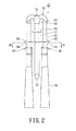
- Fig. 2 is a schematic diagram showing a jet pump 12 provided for a downcomer section (merely, downcomer) 11 of the BWR 10.
- a reactor core 15 is disposed in a rector pressure vessel 13, and the downcomer section 11 is formed in a sleeve or annular shape between a core shroud 16 surrounding the reactor core 15 and the reactor pressure vessel 13.
- a plurality of jet pumps 12 are disposed in the circumferential direction to cause forced circulation of a primary coolant in the reactor pressure vessel 13 from a core lower plenum 17 into the reactor core 15.
- Reference numeral 19 denotes a shroud supporting plate that supports the core shroud 16.
- a shroud head 20 covering a core upper plenum 18 is located above the reactor core 15, and a steam separator 21 is disposed above the shroud head 20 with a stand pipe 22 interposed therebetween.
- a steam dryer 23 is disposed above the steam separator 21. The steam dryer 23 dries the separated steam from the steam separator 21 and supplies the resulting dried steam to a steam turbine, not shown, as a main steam through a main steam system so as to drive the steam turbine.
- reactor recirculation system 25 is configured to cause forced circulation of the primary coolant in the reactor pressure vessel 13 into the reactor core 15 through the jet pumps 12 by the action of a reactor recirculation pump 26, which is an external pump, to remove heat generated in the reactor core 15.
- the reactor recirculation system 25 controls the reactor thermal power (the amount of steam generated) by adjusting the pump rate (pumping speed) of the reactor recirculation pump 26 to change the flow rate of the coolant supplied to the reactor core 15.
- a plurality of jet pumps 12, sixteen or twenty jet pumps 12, for example, are disposed at regular intervals in the downcomer section 11 in the reactor pressure vessel 13.
- the plurality of jet pumps 12 arranged outside the reactor core 15 in the circumferential direction thereof operate to cause the forced circulation of the coolant in the reactor pressure vessel 13.
- a driving fluid for the jet pump 12 is a discharge flow from the recirculation pump 26, which is an external pump.
- the driving fluid is introduced to the reactor recirculation pump 26 from the downcomer section 11 in the lower portion of the reactor pressure vessel 13 through an intake pipe 28, and the driving fluid is then raised in pressure by the reactor recirculation pump 26.
- the pressure-raised driving fluid then passes through a discharge pipe 29 and is divided by header duct, not shown, into a plurality of branch flows, which are introduced into the respective jet pumps 12.
- the reactor recirculation pump 26 has a capability of circulating reactor water, which serves as a coolant.
- the reactor water (i.e., driving fluid) discharged by the reactor recirculation pump 26 flows through the discharge pipe 29 to a riser pipe 31 of the jet pump 12 in the reactor pressure vessel 13, turns around at an elbow portion 32 and is introduced to a pump nozzle 35.
- the pump nozzle 35 guides the driving fluid along with reactor water (i.e., driven fluid) drawn in from the surrounding to an inlet mixer pipe 33, where the driving fluid is sufficiently mixed with the sucked-in fluid.
- the resulting mixed fluid restores pressure in a diffuser 34 and then is sent to the reactor core 15 through the core lower plenum 17.
- the jet pump 12 essentially includes the riser pipe 31 that extends from a recirculation inlet nozzle 30 in the downcomer section 11, the elbow portions 32 composed of a 180-degree-bend provided at the top of the riser pipe 31, inlet mixer pipes 33 disposed on the downstream side of the elbow portions 32, and diffusers 34 located on the downstream side of the inlet mixer pipes 33.
- the elbow portion 32 divides the driving fluid flowing up through the riser pipe 31 into left and right branch flows, makes the branch flows turn around and guides the branch flows to the pump nozzles 35.
- the jet pump 12 includes the pump nozzles 35 connected to the elbow portions 32 composed of a 180-degree-bend.
- the inlet mixer pipe 33 mixes the driving fluid and the driven fluid from a bell mouth 36, which guides the driven fluid (sucked-in fluid) drawn in from the surrounding reactor water by the driving fluid ejected from the pump nozzle 35.
- Each of the diffusers 34 is connected to the downstream side of the inlet mixer pipe 33, and fixed to the pump deck 37 at the lower end thereof to thereby feed the mixed fluid into the core lower plenum 17.
- the jet pump 12 has mechanical fitting portions 39 and 40 at inlets of the elbow portions 32 and the diffusers 34.
- the elbow portions 32, the pump nozzles 35 and the inlet mixer pipes 33 are made to be removable by the location of the fitting portions 39 and 40.
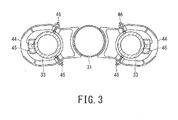
- the inlet mixer pipe 33 is fixed to the riser pipe 31 by riser brackets 44 fixed to the riser pipe 31.
- the lower end portion of the inlet mixer pipe 33 is fitted into the upper portion of the diffuser 34, and the mechanical fitting portion 40 at the upper portion of the diffuser 34 serves as a slip joint.
- the riser pipe 31 of the jet pump 12 is fixed to and supported by a riser brace 43 welded to the inner wall of the reactor pressure vessel 13.
- the riser brackets 44 that secure the inlet mixer pipes 33 are fixed on the opposite sides of the riser pipe 31.
- the inlet mixer pipe 33 is supported at three points on and fixed to the riser bracket 44 by a wedge 45 and set screws 46.
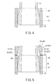
- the inlet mixer pipe 33 has a swelling portion at the lower end thereof. As shown in Fig. 4 , the lower portion of the inlet mixer pipe 33 is fitted into the upper portion of the diffuser 34 to form the slip joint 40. The inlet mixer pipe 33 and the diffuser 34 are coupled to each other by the slip joint 40.
- the slip joint 40 has a narrow clearance (minute gap) for absorbing a thermal expansion and adjustment at the time of installation, and a clearance flow channel 48, that is, a minute gap flow channel, is formed.
- a clearance flow that is, a leak flow, is produced by the fluid feeding pressure in the jet pump 12.
- the clearance flow channel 48 in the slip joint 40 between the inlet mixer pipe 33 and the diffuser 34 has an expanding clearance flow channel shape that gradually expands as it goes in the direction of the clearance flow (downstream).
- the clearance flow channel 48 in the slip joint 40 has the expanding clearance flow channel shape, the additive damping of the clearance flow tends to serve as a negative damping force.
- the flow rate of the clearance flow exceeds a certain limit value, the flow of the fluid becomes unstable, and a vibration having a large amplitude referred to as a self-excited vibration can occur.
- the clearance flow has a tapered clearance flow channel shape that tapers as it goes in the direction of the clearance flow, the additive damping of the clearance flow serves as a positive damping force, and the self-excited vibration is suppressed.
- the minute gaps 41 of the slip joint 40 forming the mechanical fitting portion between the inlet mixer pipe 33 and the diffuser 34 has a width of 1 mm or less, preferably a width of 0.13 mm to 0.3 mm.
- the flow rate (leak flow rate or speed) of the clearance flow in the expanding clearance flow channel 48 through the minute gap 41 of the slip joint 40 is as low as approximately 0.1 % or less of the total flow rate of the jet pump 12 but still is several tens of liters per minute to several hundreds of liters per minutes, although it is small.
- the clearance flow of this flow rate may cause a self-excited vibration.
- a vibration suppressing device 50 is provided on the top of the diffuser 34 so as to extend the clearance flow channel 48 in the slip joint 40, as shown in Fig. 5 .
- the vibration suppressing device 50 provides an extension flow channel 51 that adds to the length of the expanding clearance flow channel 48 in the slip joint 40 on the top (upper end in the illustration) of the diffuser 34.
- the extension flow channel 51 is an extension clearance flow channel formed between the inner surface of an extension sleeve 53 disposed on the top of the diffuser 34 with a metal seal 52 interposed therebetween and the outer surface of the inlet mixer pipe 33.
- the vibration suppressing device 50 includes an extension sleeve 53 formed by two semi-cylindrical sleeve members 53a and 53b fixed to each other by fastening plates 56 applied to the outside of the junctures of the sleeve members and bolts 57.
- the junctures may have various shapes other than the flat surface, such as a stepped shape.
- the inner surface of the extension sleeve 53 is tapered so that the inner diameter of the extension sleeve 53 gradually decreases as it goes away (downstream) from the upper end of the diffuser 34.
- the outer diameter of the extension sleeve 53 is approximately equal to the outer diameter of the diffuser 34.
- the length (height) of the extension sleeve 53 is approximately 40 mm to 90 mm, for example.
- the length of the extension sleeve 53 is approximately equal to the length of the portion of the inlet mixer pipe 33 inserted into the diffuser 34.
- the vibration suppressing device 50 is disposed on the top of the diffuser 34 so as to provide a configuration so that the extension clearance flow channel (extension flow channel) 51 formed between the inner surface of the extension sleeve 53 and the outer surface of the inlet mixer pipe 33 has a tapered shape in contrast to the clearance flow channel 48 in the slip joint 40.
- the vibration suppressing device 50 is configured so that the extension clearance flow channel 51 has a tapered shape, the additive damping of the clearance flow (leak flow) having passed through the expanding clearance flow channel 48 in the slip joint 40 tends to serve as a positive damping force.
- the extension flow channel 51 having the tapered shape additionally provided as an extension clearance flow channel can make the clearance flow therein serve as a positive damping force.
- the extension clearance flow channel 51 has the tapered shape and applies a positive damping force to the clearance flow, the shape of the inlet mixer pipe 33 does not change. Therefore, the existing inlet mixer pipe 33 remains useful.
- the vibration suppressing device 50 provided on the top (upper end portion) of the diffuser 34 has the extension clearance flow channel 51 having a tapered shape, and thus can apply a positive damping force to the clearance flow in the extension clearance flow channel 51 and achieve vibration suppression. If the extension clearance flow channel 51 is configured so that the positive damping force applied to the clearance flow in the extension clearance flow channel 51 exceeds the negative damping force applied to the flow in the slip joint 40, the total additive damping exerted in the expanding clearance flow channel 48 in the slip joint 40 and the extension clearance flow channel 51 having the tapered shape is made to serve as a positive damping force to achieve a self-excited vibration suppression effect.
- the hydrodynamic characteristics of the jet pump 12 correspond to MN characteristics of the jet pump 12 and evaluated in terms of the magnitude of the MN ratio, which indicates how much pump driving force is needed for obtaining a required flow rate of the nuclear power plant.
- the MN characteristics indicate a relationship between the M ratio, which is a ratio of the total flow rate to the driving flow rate, and the N ratio, which is a ratio of the lift of the jet pump to the driving lift.
- the metal seal 52 between the end surface of the upper portion of the diffuser 34 and the end surface of the lower portion of the extension sleeve 53 of the vibration suppressing device 50, the liquid leakage through the gap between the end surfaces can be prevented.
- the vibration suppressing device 50 has a dividable structure to be capable of being mounted to surround the inlet mixer pipe 33 in an annular configuration, and the sleeve members 53a and 53b of the vibration suppressing device 50 have bolt holes 58 and are fastened to each other with the fastening plates 56 and the bolts 57 after the vibration suppressing device 50 is placed on the top of the diffuser 34.
- the vibration suppressing device 50 can be mounted or installed without removing the inlet mixer pipe 33 from the diffuser 34.
- the extension clearance flow channel 51 of the extension sleeve 53 has a structure so that the total additive damping by the fluid in the clearance flow channel 48 in the slip joint 40 and the extension clearance flow channel 51 becomes positive.
- the additive damping by the fluid can be determined from the relationship between the flow channel resistance (force) and the fluid inertia (fluid inertial force) of the clearance flow (minute flow, leakage flow, leak flow) flowing through the entire clearance flow channels 48 and 51. If the additive damping by the fluid is positive, no self-excited vibration occurs.
- the extension clearance flow channel 51 of the extension sleeve 53 is configured so as to overcome or eliminate any condition under which the additive damping by the fluid in the clearance flow channel 48 in the slip joint 40 and the extension clearance flow channel 51 in the extension sleeve 53 becomes negative, and also, any condition under which the additive damping by the fluid becomes negative is excluded from the operational conditions of the actual nuclear power plant.
- a self-excited vibration which may occur in the slip joint 40 that couples the inlet mixer pipe 33 and the diffuser 34 to each other because of the clearance flow caused by the fluid feeding pressure in the jet pump 12 can be suppressed while maintaining the hydrodynamic characteristics of the jet pump 12 without requiring the replacement of the inlet mixer pipe 33 and the diffuser 34.
- the configuration of the boiling water reactor (BWR) 10 of the second embodiment is generally the same as that of the BWR shown in Figs. 1 and 2 , and therefore, the same components as those in the first embodiment will be denoted by the same reference numerals, and redundant description thereof will be simplified herein.
- Fig. 7 is a partial vertical sectional view of a vibration suppressing device 50A for a jet pump 12A according to the second embodiment incorporated in the BWR 10.
- the vibration suppressing device 50A for the jet pump 12A includes the slip joint 40 provided at the coupling portion of the inlet mixer pipe 33 and the diffuser 34 and an extension sleeve 53A disposed on the top of the diffuser 34.
- the extension sleeve 53A of the vibration suppressing device 50A may be disposed on the top (upper end in the illustration) of the diffuser 34 with a metal seal interposed therebetween.
- the vibration suppressing device 50A is disposed on the top of the diffuser 34 and forms an extension clearance flow channel 51A having the extended length of the expanding clearance flow channel 48 in the slip joint 40.
- the vibration suppressing device 50A is configured so that the extension clearance flow channel 51A formed between the inner surface of the extension sleeve 53A and the outer surface of the inlet mixer pipe 33 has a tapered shape in contrast to the expanding clearance flow channel 48 in the slip joint 40.
- the inner surface of the extension sleeve 53A is provided in a manner eccentric with respect to the inlet mixer pipe 33.
- the inner surface of the eccentrically disposed extension sleeve 53A is in contact with the outer surface of the inlet mixer pipe 33 at a point of contact CP.
- the vibration suppressing device 50A of the second embodiment of the structure mentioned above although the additive damping force by the clearance flow passing through the expanding clearance flow channel 48 in the slip joint 40 coupling the inlet mixer pipe 33 and the diffuser 34 to each other tends to serve as a negative damping force, the additive damping force by the fluid in the tapered extension flow channel 51A additionally provided can serve as a positive damping force.
- the jet pump 12 attains the self-excited vibration suppression effect.
- the vibration suppressing device 50A since the inner surface of the vibration suppressing device 50A is eccentrically disposed with respect to the inlet mixer piper 33, the positive damping force (vibration suppression force) in the extension flow channel 51A increases.
- Fig. 9 shows a graph representing a result of an experiment conducted on an annular clearance flow channel similar to the clearance flow channel in the slip joint 40 of the jet pump 12 which is constructed so as to apply a negative damping force, the experiment result showing the relationship between the clearance flow rate and the amplitude of the vibration of the components (the inlet mixer pipe 33 and the extension sleeve 53A) forming the annular clearance flow channel.
- This experiment was conducted for three different eccentricities: 0% (when the vibration suppressing device 50A is concentrically disposed with respect to the inlet mixer pipe 33), 25% and 50%.
- the values of the flow rate and the amplitude shown in Fig. 9 are dimensionless maximum values.
- a self-excited vibration begins at a flow rate at which the amplitude abruptly increases.
- the flow rate at which the vibration begins increases, that is, the self-excited vibration is less likely to occur.
- eccentrically disposing the extension sleeve 53A of the vibration suppressing device 50 with respect to the inlet mixer pipe 33 can provide an effect of delaying occurrence of the self-excited vibration even if the negative damping force is exerted and facilitating suppression of the self-excited vibration.
- the extension sleeve 53A is in contact with the inlet mixer pipe 33, the mechanical contact provides an additional, positive structural damping force, so that the vibration suppression effect is enhanced. Furthermore, if a lateral load is exerted on the inlet mixer pipe 33 at the point of contact CP, the lateral load serves as a resistive force against the vibration of the inlet mixer pipe 33 and advantageously reduces the amplitude of the vibration.
- the vibration suppressing device 50A even if the vibration suppressing device 50A is provided, it is not required for the inlet mixer pipe 33 and the diffuser 34 be modified in shape , and hence, not necessary to be replaced, so that the hydrodynamic characteristics of the jet pump 12 is maintained, and the same effects and advantages as those of the first embodiment can be achieved.
- the self-excited vibration that may occur in the slip joint 40 as the coupling portion of the inlet mixer pipe 33 and the diffuser 34 because of the clearance flow caused by the fluid feeding pressure in the jet pump 12 can be suppressed while maintaining the hydrodynamic characteristics of the jet pump 12 without requiring the replacement of the inlet mixer pipe 33 and the diffuser 34.
- the vibration suppressing device 50A is in contact with the outer surface of the inlet mixer pipe 33 at the point of contact CP in the above description made with reference to Figs. 7 and 8 , as can be seen from the description of Fig. 9 , the vibration suppressing device 50A can produce a similar positive damping force as far as it is eccentrically disposed with respect to the inlet mixer pipe 33 even if it is not in contact with the inlet mixer pipe 33.
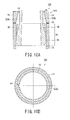
- a protrusion 64 may be formed on the inner surface of the extension sleeve 53 so as to come into contact with the inlet mixer pipe 33 without being eccentrically disposed as shown in Figs. 10A and 10B .
- the total additive damping (by the fluid) applied in the expanding clearance flow channel 48 in the slip joint 40 and the tapered extension clearance flow channel 51A 1 can be made to serve as a positive damping force to achieve a self-excited vibration suppression effect.
- the configuration of the boiling water reactor (BWR) 10 according to the third embodiment is generally the same as that of the BWR shown in Figs. 1 and 2 , and therefore, the same components as those in the first embodiment will be denoted by the same reference numerals, and redundant description thereof will be omitted or simplified herein.
- Fig. 11 is a partial vertical sectional view of a vibration suppressing device 50B for a jet pump 12B according to the third embodiment incorporated in the BWR 10.
- the vibration suppressing device 50B for the jet pump 12B of the third embodiment includes the slip joint 40 provided at the coupling portion of the inlet mixer pipe 33 and the diffuser 34 and an extension sleeve 53B disposed on the top of the diffuser 34.
- the vibration suppressing device 50B is further provided with an insertion guide 60 that facilitates the installation of the vibration suppressing device 50B to the top of the diffuser 34.
- the insertion guide 60 has a tapered insertion end portion so that the smoothness of the clearance flow in an expanding clearance flow channel 48B is achieved.
- the vibration suppressing device 50B is provided with a plurality of insertion guides 60, which is to be inserted into the expanding clearance flow channel 48B in the slip joint 40, integrally formed at the bottom of the extension sleeve 53B.
- the insertion guides 60 facilitate the insertion of the extension sleeve 53B.
- a metal seal that prevents fluid leakage may be disposed between the diffuser 34 and the extension sleeve 53B.
- the shape of the expanding clearance flow channel 48B in the slip joint 40 and the tapered clearance flow channel 51 B on the downstream side can be modified so as to make smooth the flow in the entire clearance flow channel. Accordingly, the extension sleeve 53B of the vibration suppressing device 50B can provide a reduced thickness, thereby more easily positioning the vibration suppressing device 50B.
- the third embodiment is designed for the ease of mounting of the vibration suppressing device 50B, and hence, the insertion guides 60 protruding downward are integrally formed on the inner side of the lower end portion of the extension sleeve 53B to improve the ease of mounting of the extension sleeve 53B onto the top of the diffuser 34.
- the vibration suppressing device 50B for the jet pump 12B can be more easily disposed on the top of the diffuser 34 at the slip joint 40 that couples the inlet mixer pipe 33 and the diffuser 34 to each other, and can suppress a self-excited vibration due to the clearance flow caused by the fluid feeding pressure in the jet pump 12B while maintaining the hydrodynamic characteristics of the jet pump 12B without requiring the replacement of the inlet mixer pipe 33 and the diffuser 34.
- a single insertion guide 60 may be provided over the entire circumference of the lower end of the extension sleeve 53B, or a plurality of insertion guides 60 may be provided at regular intervals (every 90°, for example).
- the insertion guides 60 are provided along the inner circumference of the lower end portion of the extension sleeve 53B.
- an insertion guide 60B is provided along the outer circumference of the lower end portion of an extension sleeve 53B 1 as shown in Fig. 12 .
- a single insertion guide 60B may be provided over the entire circumference of the lower end of the extension sleeve 53B 1 , or a plurality of insertion guides 60B can be provided at regular intervals (every 90°, for example).
- the vibration suppressing device 50B for the jet pump 12B can also be more easily mounted on the top of the diffuser 34 owing to the location of the insertion guide 60B integrally formed along the outer circumference of the lower end portion of the extension sleeve 53B 1 .
- the vibration suppressing device 50B can suppress a self-excited vibration due to the clearance flow caused by the fluid feeding pressure in the jet pump 12B while maintaining the hydrodynamic characteristics of the jet pump 12B without requiring the replacement of the inlet mixer pipe 33 and the diffuser 34.
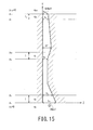
- Figs. 13 to 15 are views illustrating a configuration of a vibration suppressing device for a jet pump according to a fourth embodiment of the present invention.
- the configuration of the boiling water reactor (BWR) 10 is generally the same as that of the BWR shown in Figs. 1 and 2 , and therefore, the same components as those in the first embodiment will be denoted by the same reference numerals, and redundant description thereof will be omitted or simplified herein.
- Fig. 13 is a partial vertical sectional view of a vibration suppressing device 50C for a jet pump 12C according to the fourth embodiment incorporated in the BWR 10.
- the vibration suppressing device 50C for the jet pump 12C of the fourth embodiment includes the slip joint 40 provided at the coupling portion of the inlet mixer pipe 33 and the diffuser 34 and an extension sleeve 53C disposed on the top of the diffuser 34.
- a tapered extension clearance flow channel 51 C is formed between the inner surface of the extension sleeve 53C and the outer surface of the inlet mixer pipe 33.
- the clearance flow channel 48 in the slip joint 40 and the extension clearance flow channel 51C form the entire clearance flow channels 48, 51C.
- the extension clearance flow channel 51C formed between the inner surface of the vibration suppressing device 50C and the outer surface of the inlet mixer pipe 33 provides a tapered shape.
- the outlet width Wo of the extension clearance flow channel 51C is equal to or smaller than 5.3 times the minimum clearance width Wmin of the clearance flow channel 48 in the slip joint 40. That is, a relation holds: Wo/Wmin ⁇ 5.3.
- the limit flow rate at which a self-excited vibration is caused by the clearance flow guided through the clearance flow channel is derived from an equation of motion and an equation of continuity for the clearance flow field and is indicated by determining whether the sign of an additive damping coefficient of a damping force term in an equation on a non-steady hydrodynamic force acting on the wall of the clearance is positive or negative.
- a dimensionless equation of motion and a dimensionless equation of continuity on a clearance flow in a simple tapered clearance flow channel, and boundary conditions at an inlet and an outlet are generally expressed by the following governing equations (1) to (4), in the case where the fluid is a non-steady fluid.
- the clearance flow channels 48 and 51C of the vibration suppressing device 50C of the four-way-valve type according to this embodiment disposed on the slip joint 40 have a complicated clearance flow channel shape as a whole, as shown in Fig. 13 .
- the equations (1) to (4) can be discretized to reduce a transfer matrix calculation of each flow channel element into a governing equation on a non-steady fluid.
- reference symbol Y denotes the axial direction of the clearance
- reference symbol Z denotes the width direction of the clearance
- reference letters h, I, p and q with suffixes denote the clearance amount (flow channel width), the length of each flow channel element of the complicated clearance flow channel, the pressure (widening) on each flow channel element, and the flow rate (amplitude) of each flow channel element, respectively.
- the clearance flow is a one-dimensional flow parallel with the Y axis
- the transfer matrix of the n-th flow channel element of the clearance flow channel can be expressed by the following equation (5).
- Reference symbol In denotes the length of the n-th flow channel element of the complicated clearance flow channel divided into N elements, and quantities h, I, p and q in each flow channel element l 1 , ..., l n , ... l N that are the N divisions of the complicated clearance flow channel are dimensionless quantities.
- the dimensionless pressure amplitude pn+1 can be expressed by a relation (oscillation equation) of the dimensionless amplitude e of the clearance wall and the dimensionless velocity amplitude qw of the clearance wall as shown by the following equation (11).
- the pressure amplitude pn+1 can be expressed as a sum of a portion proportional to the velocity amplitude qw of the clearance wall and a portion proportional to the amplitude e of the clearance wall.
- an amplitude f of a non-steady fluid force can be expressed by a relation (amplitude equation) of a factor of proportionality Cfe of the dimensionless amplitude e of the clearance wall and a factor of proportionality Cfw of the dimensionless velocity amplitude qw of the clearance wall.
- Equation (12) The coefficients in the equations (13) and (14) are complex numbers.
- a displacement z ⁇ ( ⁇ ) and a non-steady fluid force F ⁇ ' ( ⁇ ) are defined by the following equations (16) and (17). Therefore, from the equation (15), a governing equation on the non-steady fluid force expressed by the equation (18) can be derived.
- the coefficient of acceleration in the first term of the right-hand side denotes additive mass
- the coefficient of velocity in the second term denotes additive damping
- the third term denotes additive rigidity.
- Each term in the right-hand side is added to the structure of the vibration suppressing device 50C for the jet pump, and the added value has an opposite sign.
- Fig. 16 is a graph showing, by the solid line F, a relationship between the outlet width Wo of an extension clearance flow channel 51 C 1 in the case where the vibration suppressing device 50C is actually provided at the slip joint 40 of the vibration suppressing device 50C for the jet pump 12C and the clearance flow rate at which the left-hand side of the expression (19) is 0 and a self-excited vibration begins to occur (limit flow rate at which a self-excited vibration occurs).
- the dot-and-dash (chain) line G shows the clearance flow rate at which a self-excited vibration begins to occur (limit flow rate at which a self-excited vibration occurs) in the case where the extension sleeve 53C of the vibration suppressing device 50C is not provided.
- the horizontal axis indicates the outlet width Wo of the clearance flow channel in the case where the vibration suppressing device 50C is provided at the slip joint 40.
- the outlet width Wo is shown as a ratio to the minimum clearance width Wmin of the clearance in the slip joint 40 between the inner surface of the diffuser 34 and the outer surface of the inlet mixer pipe 33.
- the vertical axis of the graph indicates the limit flow rate at which a self-excited vibration occurs, which is shown as a ratio to the limit flow rate at which a self-excited vibration occurs in the case where the vibration suppressing device 50C is not provided.
- the limit flow rate is higher than the limit flow rate in the case where the vibration suppressing device 50C is not provided. In other words, the allowance for the self-excited vibration is improved, and the vibration suppression effect begins to appear.
- the vibration suppressing device 50C has a dividable structure so as to be mounted to surround the inlet mixer pipe 33 in an annular configuration. Therefore, the sleeve members of the extension sleeve 53 of the vibration suppressing device 50C have bolt holes 58 (see fig, 6 ) and are fastened to each other with the fastening plates 56 and the bolts 57 after the vibration suppressing device 50C is disposed on the top of the diffuser 34. With such a configuration, the vibration suppressing device 50C can be mounted without requiring the movement of the inlet mixer pipe 33.
- the limit flow rate at which a self-excited vibration can occur in the slip joint 40 that couples the inlet mixer pipe 33 and the diffuser 34 to each other because of the clearance flow in the clearance flow channel 48 caused by the fluid feeding pressure in the jet pump 12 can be increased to increase the allowance for a self-excited vibration to thereby achieve a vibration suppression effect.
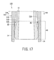
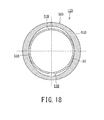
- Figs. 17 and 18 are a vertical sectional view and a horizontal sectional view of a vibration suppressing device for a jet pump according to a fifth embodiment of the present invention.
- the configuration of the boiling water reactor (BWR) 10 generally does not differ from that of the BWR shown in Figs. 1 and 2 , and therefore, the same components as those in the first embodiment will be denoted by the same reference numerals, and redundant description thereof will be omitted or simplified herein.
- Fig. 17 is a partial vertical sectional view of a vibration suppressing device 50D for a jet pump 12D according to the fifth embodiment incorporated in the BWR 10.
- the vibration suppressing device 50D for the jet pump 12D of the fifth embodiment includes the slip joint 40 provided at the coupling portion of the inlet mixer pipe 33 and the diffuser 34 and an extension sleeve 53D disposed on the top of the diffuser 34.
- the vibration suppressing device 50D is provided with a tapered extension clearance flow channel 51 D formed between the inner surface of the extension sleeve 53D and the outer surface of the inlet mixer pipe 33.
- the clearance flow channel 48 in the slip joint 40 and the extension clearance flow channel 51 D form the entire structure of the clearance flow channels 48 and 51 D.
- the extension clearance flow channel 51 D has a tapered shape, and the outlet width thereof is equal to or smaller than 5.3 times the minimum clearance width of the clearance in the slip joint 40.
- the vibration suppressing device 50D is disposed on the top (upper end in the illustration) of the diffuser 34 so as to elongate the length of the clearance flow channel 48 in the slip joint 40.
- the extension clearance flow channel 51 D formed between the inner surface of the vibration suppressing device 50D and the outer surface of the inlet mixer pipe 33 has a tapered shape in the direction of the clearance flow.
- the outlet width of the extension clearance flow channel 51 D formed between the inner surface of the vibration suppressing device 51 D and the outer surface of the inlet mixer pipe 33 gradually changes in the circumferential direction of the outer surface of the inlet mixer pipe 33, and the inner circumference of the vibration suppressing device 50D has an elliptical or oval shape.
- the outlet width of the extension clearance flow channel 51 D formed inside the inner circumference of the vibration suppressing device 50D at the ends in the major axis direction is equal to or smaller than 5.3 times the minimum clearance width of the clearance in the slip joint 40 formed between the inner surface of the diffuser 34 and the inlet mixer pipe 33. Therefore, as in the fourth embodiment, the allowance for a self-excited vibration can be also improved, and the vibration suppression effect can be achieved.
- the inner surface of the extension sleeve 53D of the vibration suppressing device 50D is in contact with the outer surface of the inlet mixer pipe 33 at two points at the ends in the minor axis direction.
- the contact with the inlet mixer pipe 33 exerts a structural damping force against a vibration, and the vibration suppression effect is enhanced by the positive structural damping force.
- the vibration suppressing device 50D attains a vibration amplitude reduction effect.
- the limit flow rate at which a self-excited vibration will occur in the slip joint 40 that couples the inlet mixer pipe 33 and the diffuser 34 to each other because of the clearance flow in the clearance flow channel caused by the fluid feeding pressure in the jet pump 12D can be increased, thus increasing the allowance for a self-excited vibration and achieving the vibration suppression effect.
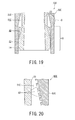
- Figs. 19 and 20 are views showing a configuration of a vibration suppressing device for a jet pump according to a sixth embodiment of the present invention.
- the configuration of the boiling water reactor (BWR) 10 generally does not differ from that of the BWR shown in Figs. 1 and 2 , and therefore, the same components as those in the first embodiment will be denoted by the same reference numerals, and redundant description thereof will be simplified herein.
- Fig. 19 is a partial vertical sectional view of a vibration suppressing device 50E for a jet pump 12E according to the sixth embodiment incorporated in the BWR 10.
- the vibration suppressing device 50E for the jet pump 12E of the sixth embodiment includes the joint 40 provided at the coupling portion of the inlet mixer pipe 33 and the diffuser 34 and an extension sleeve 53E disposed on the top (upper end in the illustration) of the diffuser 34.
- a circumferential labyrinth groove 62 is formed in the inner surface of the extension sleeve 53E of the vibration suppressing device 50E in a stepped, inclined or spiral configuration.
- the vibration suppressing device 50E for the jet pump 12E is disposed on the top of the diffuser 34 so as to elongate the length of the expanding clearance flow channel 48 in the slip joint 40 provided at the coupling portion of the inlet mixer pipe 33 and the diffuser 34.
- the vibration suppressing device 50E is configured to provide a tapered extension clearance flow channel 51 E above (downstream of) the expanding clearance flow channel 48 in the slip joint 40.
- the extension clearance flow channel 51 E of the vibration suppressing device 50E disposed on the top of the diffuser 34 provides a tapered shape.
- the inner surface of the extension sleeve 53E of the vibration suppressing device 50E has a structure in which the total additive damping force acting on the whole of the clearance flow channels serves as a positive damping force (vibration suppression force), and the circumferential labyrinth groove 62 is formed in the inner surface of the extension sleeve 53E as shown in Fig. 19 .
- the circumferential labyrinth groove 62 not only has a self-excited vibration suppression effect but also disturbs the slip flow (leak flow) of the fluid to thereby cause the resistance of the entire clearance flow channel to the flow.
- the circumferential labyrinth groove 62 may not be formed in a direction perpendicular to the direction of the clearance flow (leak flow) but may be formed in an oblique direction or in a spiral or step-like configuration.
- the depth of the circumferential labyrinth groove 62 may not be uniform.
- the width and depth of the circumferential labyrinth groove 62 is several millimeters or less, for example, 2 mm.
- the vibration suppressing device 50E for the jet pump 12E can suppress a self-excited vibration in the slip joint 40 that couples the inlet mixer pipe 33 and the diffuser 34 to each other because of the clearance flow caused by the fluid feeding pressure in the jet pump 12E while maintaining the hydrodynamic characteristics of the jet pump 12E without requiring the replacement of the inlet mixer pipe 33 and the diffuser 34.
- the configuration of the boiling water reactor (BWR) 10 generally does not differ from that of the BWR shown in Figs. 1 and 2 , and therefore, the same components as those in the first embodiment will be denoted by the same reference numerals, and redundant description thereof will be omitted or simplified herein.
- a vibration suppressing device 50F for a jet pump according to this embodiment has basically the same configuration as the vibration suppressing device 50 shown in Fig. 5 .
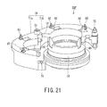
- Fig. 21 illustrates an example of the installation of a vibration suppressing clamp 70 of the vibration suppressing device 50F disposed on the top of the diffuser 34.
- the vibration suppressing clamp 70 is composed of an extension sleeve, which is composed of two semi-cylindrical clamp members (sleeve members) 71 a and 71 b coupled to each other by means of hinge 72, which forms a link portion, in such a manner that the clamp members 71 a and 71 b can be opened and closed.
- the paired clamp members 71 a and 71 b are hinged to each other at one end thereof by a washer-faced bolt 73 in such a manner that the clamp members 71 a and 71 b can be opened and closed.
- the clamp members 71 a and 71 b are coupled to each other by step joint (concave/convex engagement) at a fitting portion 74 at the other end thereof.
- the vibration suppressing clamp (extension sleeve) 70 is suspended by a hoist, not shown, and introduced into the reactor pressure vessel 13 with the fitting portion 74 being opened.
- the suspended and introduced vibration suppressing clamp 70 is stopped near the upper end portion of the diffuser 34, and then, the fitting portion 74 is closed so as to surround the inlet mixer pipe 33 from outside.
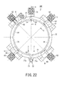
- the vibration suppressing clamp 70 in the annular shape is formed as shown in Fig. 22 .
- a hexagon head bolt 75 as fastening means is inserted into and supported by one clamp member 71 b of the vibration suppressing clamp 70, and a wedge-shaped block 77 is screwed to the hexagon head bolt 75 in such a manner that the wedge-shaped block can be raised and lowered.
- the hexagon head bolt 75 is formed with a circumferential groove at an intermediate portion thereof, with which a locking pin 78 is engaged so as to prevent the hexagon head bolt 75 from dropping off. In this way, the hexagon head bolt 75 is inserted into one clamp member 71b and rotatably supported thereby.
- the paired clamp members 71 a and 71 b of the vibration suppressing clamp 70 which is the extension sleeve, are closed and coupled by each other by the step joint to form the fitting portion 74.
- the hexagon head bolt 75 is rotated, the wedge-shaped block 77 lowers, the downward-facing inclined surface of the wedge-shaped block 77 comes into contact with an outer shoulder (upward-facing inclined surface) 79 of the other clamp member 71 b, and the clamp member 71 b is pressed against the top portion of the diffuser 54.
- a circumferential protrusion is formed on the inner circumferential portion of the vibration suppressing clamp 70 and comes into surface contact with a stepped portion 76 formed in an inner area of the top portion of the diffuser 34 from above.
- the diffuser 34 is provided with a plurality of, such as four, blade-shaped protruding guides 80 arranged radially.
- the protruding guides 80 are integrally formed on the top (upper end) portion of the diffuser 34 along the outer periphery thereof so as to protrude upward.
- the annular vibration suppressing clamp 70 is formed with guide windows 81 for guiding the raising and lowering of the clamp 70 in correspondence with the protruding guides 80. When the vibration suppressing clamp 70 is lowered, the protruding guides 80 are inserted in and guided by the guide windows 81 so that the vibration suppressing clamp 70 is disposed on the top of the diffuser 34.
- a plurality of, such as four, hexagon head bolts 82 located near the protruding guides 80 are rotated to move a screwed wedge-shaped blocks 83 upward along the vibration suppressing clamp 70 as shown in Fig. 24 .
- the upward-facing inclined surfaces of the wedge-shaped blocks 83 are pressed against the lower end (downward-facing inclined surfaces) of the protruding guides 80, and thus, the vibration suppressing clamp 70 can be held and fixed on the diffuser 34.
- the hexagon head bolt 75 at the fitting portion 74 is rotated to hardly press the vibration suppressing clamp 70 against the top of the diffuser 34 for fixing.
- the hexagon head bolt 82 have a circumferential groove formed in a middle portion thereof, with which a locking pin 84 is engaged so as to prevent the hexagon head bolt 82 from dropping off.
- the wedge-shaped block 81 can be raised and lowered by rotating the hexagon head bolt 82.
- the vibration suppressing clamp 70 of the vibration suppressing device 50F is disposed and fixed on the top of the diffuser 34, the vibration suppressing device 50F for the jet pump 12F can be stably disposed on the top of the diffuser 34 without requiring the replacement of the existing inlet mixer pipe 33.
- the vibration suppressing clamp 70 of the vibration suppressing device 50F provides an extension clearance flow channel 51 F, which extends in the length of the clearance flow channel 48 in the slip joint 40, on the top of the diffuser 34.
- the vibration suppressing clamp 70 forms an extension sleeve, and the extension clearance flow channel 51 F is formed between the inner surface of the vibration suppressing clamp 70 and the outer surface of the inlet mixer pipe 33.
- the extension clearance flow channel 51 F has a tapered flow channel shape in the direction of the clearance flow.
- the extension clearance flow channel 51 F formed by the vibration suppressing clamp 70 is a tapered flow channel, even if the additive damping force in the expanding flow channel 48 in the slip joint 40 serves as a negative damping force, the additive damping force in the extension clearance flow channel 51 F can serve as a positive damping force. If the vibration suppressing device 50F is set in its shape so that the positive damping force in the extension clearance flow channel 51 F exceeds the negative damping force in the expanding clearance flow channel 48, the total additive damping force exerted in the entire clearance flow channel 48 in the slip joint 40 and the extension clearance flow channel 51 F can be made to serve as a positive damping force, thus achieving the self-excited vibration suppression effect.
- the vibration suppressing clamp 70 Even if the vibration suppressing clamp 70 is provided, the inlet mixer pipe 33 and the diffuser 34 of the jet pump 12F can be existing ones and do not have to be replaced, so that the hydrodynamic characteristics of the jet pump 12F can be maintained without the need to replace the inlet mixer pipe 33 and the diffuser 34. Furthermore, even if the inside of the top portion of the diffuser 34 has been worn by a self-excited vibration, the vibration suppressing clamp 70 disposed provides a new tapered extension clearance flow channel 51 F, so that the vibration is suppressed.
- a modification of the seventh embodiment is designed to allow adjustment of the shape of the extension clearance flow channel 51 F formed between the outer surface of the inlet mixer pipe 33 and the inner surface of the vibration suppressing clamp 70 when the vibration suppressing clamp 70 of the vibration suppressing device 50F shown in Fig. 5 is disposed.
- the vibration suppressing clamp 70 forms an extension sleeve.
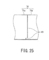
- a labyrinth 90 having a stepped fitting structure with one or more steps is radially formed in the link hinge 72 and the fitting portion 74 of the paired semi-cylindrical clamp members 71 a and 71 b as shown in Figs. 22 and 25 .
- the labyrinth 90 has an adjustment margin in the tangential direction of the diffuser 34, which allows adjustment of the shape of the clearance between the inlet mixer pipe 33 and the vibration suppressing clamp 70.
- the step portions of the stepped labyrinth 90 are in surface-contact with each other.
- the shape and position of the labyrinth 90 are not limited to those described above, and the labyrinth 90 may have any other shape and be located at any position as far as the labyrinth 90 has surfaces parallel to the tangential direction of the clamp and in contact with each other.
- the step portion may not be formed in the vicinity of an end of the clamp in the axial direction thereof as shown in Fig. 25 , but may be formed in the vicinity of the middle of the clamp.
- the shape of the labyrinth 90 may not have the stepped shape, and the labyrinth 90 may include a protrusion formed on one of the clamp members 71 a and a recess, on the other one thereof, into which the protrusion is fitted.
- the vibration suppressing clamp 70 of the vibration suppressing device 50F is fixed to the top of the diffuser 34 by rotating four hexagon head bolts 85, for example, the vibration suppressing clamp 70 is pressed from outside in a required direction, such as in a direction rotated by 90 degrees from the direction of the diameter connecting the link portion 72 and the fitting portion 74, thereby bringing a portion of the inner surface of the vibration suppressing clamp 70 into contact with the outer surface of the inlet mixer pipe 33.
- the hexagon head bolt 82 is rotated to raise the wedge-shaped block 83 so as to press the upward-facing inclined surface of the wedge-shaped block 83 against the lower end (downward-facing inclined surface) of the protruding guide 80, thereby fixing the vibration suppressing clamp 70 on the diffuser 34.
- the hexagon head bolt 75 and the wedge-shaped block 77 are provided in the vicinity of the fitting portion 74 of the vibration suppressing clamp 70.
- the hexagon head bolt 75 can be rotated to lower the wedge-shaped block 77 along the vibration suppressing clamp 70 to press the wedge-shaped block 77 against the diffuser 34 at the fitting portion 74, thereby stably fixing the vibration suppressing clamp 70.
- the shape of the extension clearance flow channel 51 F formed between the outer surface of the inlet mixer pipe 33 and the inner surface of the vibration suppressing clamp 70 can be adjusted by operating the hexagon head bolts 75 and 82.
- the extension sleeve of the vibration suppressing device is formed as a cylindrical sleeve composed of two semi-cylindrical sleeve members.
- the extension sleeve may be composed of three or more divided sleeve members or a single cylindrical sleeve member.
- the fastening means is omitted.
- the extension sleeve onto the inlet mixer pipe 33 can be easily mounted by raising and lowering the inlet mixer pipe 33 with respect to the diffuser 34.
Landscapes
- Engineering & Computer Science (AREA)
- Physics & Mathematics (AREA)
- General Engineering & Computer Science (AREA)
- Fluid Mechanics (AREA)
- Mechanical Engineering (AREA)
- Plasma & Fusion (AREA)
- High Energy & Nuclear Physics (AREA)
- Jet Pumps And Other Pumps (AREA)
- Structures Of Non-Positive Displacement Pumps (AREA)
Applications Claiming Priority (2)
| Application Number | Priority Date | Filing Date | Title |
|---|---|---|---|
| JP2013054085 | 2013-03-15 | ||
| JP2013256010A JP6162591B2 (ja) | 2013-03-15 | 2013-12-11 | ジェットポンプの振動抑制装置、ジェットポンプおよびその振動抑制方法 |
Publications (2)
| Publication Number | Publication Date |
|---|---|
| EP2778434A2 true EP2778434A2 (de) | 2014-09-17 |
| EP2778434A3 EP2778434A3 (de) | 2017-04-12 |
Family
ID=50343613
Family Applications (1)
| Application Number | Title | Priority Date | Filing Date |
|---|---|---|---|
| EP14159972.0A Withdrawn EP2778434A3 (de) | 2013-03-15 | 2014-03-14 | Schwingungsunterdrückungsvorrichtung für eine Strahlpumpe, Strahlpumpe und Schwingungsunterdrückungsverfahren dafür |
Country Status (4)
| Country | Link |
|---|---|
| EP (1) | EP2778434A3 (de) |
| JP (1) | JP6162591B2 (de) |
| MX (1) | MX355440B (de) |
| TW (1) | TWI576517B (de) |
Cited By (3)
| Publication number | Priority date | Publication date | Assignee | Title |
|---|---|---|---|---|
| EP2905478A1 (de) * | 2014-02-07 | 2015-08-12 | Kabushiki Kaisha Toshiba | Schwingungsunterdrückungsvorrichtung für Wärmepumpe sowie Strahlpumpe |
| JP2016065866A (ja) * | 2014-09-25 | 2016-04-28 | 株式会社東芝 | 沸騰水型原子炉のジェットポンプおよび沸騰水型原子炉 |
| US20170108013A1 (en) * | 2015-10-16 | 2017-04-20 | Areva Inc. | Sealing device for jet pump slip joints |
Families Citing this family (2)
| Publication number | Priority date | Publication date | Assignee | Title |
|---|---|---|---|---|
| JP6542139B2 (ja) * | 2016-02-18 | 2019-07-10 | 株式会社東芝 | ジェットポンプ及びそのディフューザ延長スリーブ |
| US10753374B2 (en) * | 2016-05-09 | 2020-08-25 | Ge-Hitachi Nuclear Energy Americas Llc | Slip joint clamps and methods for use in a nuclear reactor jet pump |
Citations (1)
| Publication number | Priority date | Publication date | Assignee | Title |
|---|---|---|---|---|
| JP2010242581A (ja) | 2009-04-03 | 2010-10-28 | Toshiba Corp | ジェットポンプおよびその振動抑制方法 |
Family Cites Families (9)
| Publication number | Priority date | Publication date | Assignee | Title |
|---|---|---|---|---|
| US4285770A (en) * | 1979-07-12 | 1981-08-25 | General Electric Company | Jet pump with labyrinth seal |
| JPS56132500A (en) * | 1980-03-19 | 1981-10-16 | Hitachi Ltd | Jet pump for nuclear furnace |
| US6394765B1 (en) * | 2000-10-18 | 2002-05-28 | General Electric Company | Jet pump slip joint clamp apparatus |
| US6450774B1 (en) * | 2000-12-21 | 2002-09-17 | General Electric Company | Method and system for a jet pump slip joint ovalization |
| US20080031741A1 (en) * | 2006-08-02 | 2008-02-07 | Torres Martin R | Jet pump slip joint with axial grooves |
| JP4546489B2 (ja) * | 2007-01-15 | 2010-09-15 | 日立Geニュークリア・エナジー株式会社 | ジェットポンプ及び原子炉 |
| JP2011196887A (ja) * | 2010-03-23 | 2011-10-06 | Hitachi-Ge Nuclear Energy Ltd | 原子炉用ジェットポンプ |
| US8964929B2 (en) * | 2010-12-30 | 2015-02-24 | Ge-Hitachi Nuclear Energy Americas Llc | Method and apparatus for a jet pump three point slip joint clamp |
| US20120219103A1 (en) * | 2011-02-25 | 2012-08-30 | Areva Np Inc. | Vibration reduction techniques for jet pump slip joints |
-
2013
- 2013-12-11 JP JP2013256010A patent/JP6162591B2/ja active Active
-
2014
- 2014-03-10 TW TW103108154A patent/TWI576517B/zh not_active IP Right Cessation
- 2014-03-13 MX MX2014003047A patent/MX355440B/es active IP Right Grant
- 2014-03-14 EP EP14159972.0A patent/EP2778434A3/de not_active Withdrawn
Patent Citations (1)
| Publication number | Priority date | Publication date | Assignee | Title |
|---|---|---|---|---|
| JP2010242581A (ja) | 2009-04-03 | 2010-10-28 | Toshiba Corp | ジェットポンプおよびその振動抑制方法 |
Cited By (4)
| Publication number | Priority date | Publication date | Assignee | Title |
|---|---|---|---|---|
| EP2905478A1 (de) * | 2014-02-07 | 2015-08-12 | Kabushiki Kaisha Toshiba | Schwingungsunterdrückungsvorrichtung für Wärmepumpe sowie Strahlpumpe |
| JP2016065866A (ja) * | 2014-09-25 | 2016-04-28 | 株式会社東芝 | 沸騰水型原子炉のジェットポンプおよび沸騰水型原子炉 |
| US20170108013A1 (en) * | 2015-10-16 | 2017-04-20 | Areva Inc. | Sealing device for jet pump slip joints |
| US10436227B2 (en) * | 2015-10-16 | 2019-10-08 | Framatome Inc. | Sealing device for jet pump slip joints |
Also Published As
| Publication number | Publication date |
|---|---|
| JP2014199243A (ja) | 2014-10-23 |
| MX2014003047A (es) | 2015-04-28 |
| MX355440B (es) | 2018-04-18 |
| JP6162591B2 (ja) | 2017-07-12 |
| EP2778434A3 (de) | 2017-04-12 |
| TWI576517B (zh) | 2017-04-01 |
| TW201506257A (zh) | 2015-02-16 |
Similar Documents
| Publication | Publication Date | Title |
|---|---|---|
| Xia et al. | Mechanism of the S-shaped characteristics and the runaway instability of pump-turbines | |
| EP2905478B1 (de) | Schwingungsunterdrückungsvorrichtung für Wärmepumpe sowie Strahlpumpe | |
| Goyder | Flow-induced vibration in heat exchangers | |
| Houde et al. | Experimental and numerical investigations on the origins of rotating stall in a propeller turbine runner operating in no-load conditions | |
| Mazur et al. | Numerical 3D simulation of the erosion due to solid particle impact in the main stop valve of a steam turbine | |
| Shahzer et al. | Investigation of cavitating vortex rope instabilities and its suppression inside a Francis turbine model with Thoma number variation | |
| JP6162591B2 (ja) | ジェットポンプの振動抑制装置、ジェットポンプおよびその振動抑制方法 | |
| Nagai et al. | Numerical and experimental analyses of static characteristics for liquid annular seals with helical grooves in seal stator | |
| Nguyen et al. | Hydrodynamic and radial force characteristics with design of a single-channel pump for wastewater treatment based on the similarity law | |
| Tanaka et al. | Suppression of cavitation surge in turbopump with inducer by reduced-diameter suction pipe with swirl brake | |
| Cervantes et al. | Extending the operational range of Francis turbines: A case study of a 200 MW prototype | |
| Childs et al. | Rotordynamic-coefficients and static (equilibrium loci and leakage) characteristics for short, laminar-flow annular seals | |
| Bourgeois et al. | Investigations of spoilers to mitigate columnar vortices in propeller turbines at speed-no-load based on steady and unsteady flow simulations | |
| Wu et al. | Pump grooved seals: A computational fluid dynamics approach to improve bulk-flow model predictions | |
| Migliorini et al. | Hybrid analysis of gas annular seals with energy equation | |
| Möller et al. | Influence of rotor tip blockage on near stall blade vibrations in an axial compressor rig | |
| Shi et al. | The influence of installation deviation on the upper guide bearing thermo-hydrodynamic characteristics of a 1000 MW giant hydropower unit | |
| Christou et al. | Characterizing flow effects of ported shroud casing treatment on centrifugal compressor performance | |
| Birajdar et al. | Prediction of flow induced vibrations in vertical turbine pumps using one-way fluid-structure interaction | |
| Gibbons et al. | Computational Fluid Dynamics Prediction of Rotordynamic Coefficients for Grooved Seals: Model and Numerical Sensitivity | |
| Wang et al. | Quantitative insights into the effect of particle stokes number on the erosion behavior in semi-open centrifugal pump: Vortex-particle-surface interaction | |
| Wang et al. | Swirling instability suppression through a honeycomb-like grid in a giant hydraulic turbine | |
| Niu et al. | Research on fluid-structure interaction characteristics of transient pressure waves in reactor coolant pump under shaft seizure accident | |
| Mazur et al. | Shape modification of an axial flow turbine nozzle to reduce erosion | |
| Pettigrew | Flow-induced vibration of nuclear power station components |
Legal Events
| Date | Code | Title | Description |
|---|---|---|---|
| 17P | Request for examination filed |
Effective date: 20140314 |
|
| AK | Designated contracting states |
Kind code of ref document: A2 Designated state(s): AL AT BE BG CH CY CZ DE DK EE ES FI FR GB GR HR HU IE IS IT LI LT LU LV MC MK MT NL NO PL PT RO RS SE SI SK SM TR |
|
| AX | Request for extension of the european patent |
Extension state: BA ME |
|
| PUAI | Public reference made under article 153(3) epc to a published international application that has entered the european phase |
Free format text: ORIGINAL CODE: 0009012 |
|
| PUAL | Search report despatched |
Free format text: ORIGINAL CODE: 0009013 |
|
| AK | Designated contracting states |
Kind code of ref document: A3 Designated state(s): AL AT BE BG CH CY CZ DE DK EE ES FI FR GB GR HR HU IE IS IT LI LT LU LV MC MK MT NL NO PL PT RO RS SE SI SK SM TR |
|
| AX | Request for extension of the european patent |
Extension state: BA ME |
|
| RIC1 | Information provided on ipc code assigned before grant |
Ipc: G21C 15/25 20060101ALI20170307BHEP Ipc: F04F 5/46 20060101ALI20170307BHEP Ipc: F04F 5/10 20060101AFI20170307BHEP Ipc: F04F 5/54 20060101ALI20170307BHEP |
|
| STAA | Information on the status of an ep patent application or granted ep patent |
Free format text: STATUS: EXAMINATION IS IN PROGRESS |
|
| 17Q | First examination report despatched |
Effective date: 20181114 |
|
| STAA | Information on the status of an ep patent application or granted ep patent |
Free format text: STATUS: THE APPLICATION HAS BEEN WITHDRAWN |
|
| 18W | Application withdrawn |
Effective date: 20190322 |