EP2778335A1 - Shower door bumper - Google Patents
Shower door bumper Download PDFInfo
- Publication number
- EP2778335A1 EP2778335A1 EP14158980.4A EP14158980A EP2778335A1 EP 2778335 A1 EP2778335 A1 EP 2778335A1 EP 14158980 A EP14158980 A EP 14158980A EP 2778335 A1 EP2778335 A1 EP 2778335A1
- Authority
- EP
- European Patent Office
- Prior art keywords
- shower door
- bumper
- channel
- sealing assembly
- shower
- Prior art date
- Legal status (The legal status is an assumption and is not a legal conclusion. Google has not performed a legal analysis and makes no representation as to the accuracy of the status listed.)
- Withdrawn
Links
Images


Classifications
-
- A—HUMAN NECESSITIES
- A47—FURNITURE; DOMESTIC ARTICLES OR APPLIANCES; COFFEE MILLS; SPICE MILLS; SUCTION CLEANERS IN GENERAL
- A47K—SANITARY EQUIPMENT; ACCESSORIES THEREFOR, e.g. TOILET ACCESSORIES
- A47K3/00—Baths; Showers; Appurtenances therefor
- A47K3/28—Showers or bathing douches
- A47K3/30—Screens or collapsible cabinets for showers or baths
- A47K3/302—Screens or collapsible cabinets for showers or baths splash guards
-
- A—HUMAN NECESSITIES
- A47—FURNITURE; DOMESTIC ARTICLES OR APPLIANCES; COFFEE MILLS; SPICE MILLS; SUCTION CLEANERS IN GENERAL
- A47K—SANITARY EQUIPMENT; ACCESSORIES THEREFOR, e.g. TOILET ACCESSORIES
- A47K3/00—Baths; Showers; Appurtenances therefor
- A47K3/28—Showers or bathing douches
- A47K3/30—Screens or collapsible cabinets for showers or baths
-
- A—HUMAN NECESSITIES
- A47—FURNITURE; DOMESTIC ARTICLES OR APPLIANCES; COFFEE MILLS; SPICE MILLS; SUCTION CLEANERS IN GENERAL
- A47K—SANITARY EQUIPMENT; ACCESSORIES THEREFOR, e.g. TOILET ACCESSORIES
- A47K3/00—Baths; Showers; Appurtenances therefor
- A47K3/28—Showers or bathing douches
- A47K3/30—Screens or collapsible cabinets for showers or baths
- A47K2003/305—Sealings between screen and bath- or showertub
-
- E—FIXED CONSTRUCTIONS
- E06—DOORS, WINDOWS, SHUTTERS, OR ROLLER BLINDS IN GENERAL; LADDERS
- E06B—FIXED OR MOVABLE CLOSURES FOR OPENINGS IN BUILDINGS, VEHICLES, FENCES OR LIKE ENCLOSURES IN GENERAL, e.g. DOORS, WINDOWS, BLINDS, GATES
- E06B3/00—Window sashes, door leaves, or like elements for closing wall or like openings; Layout of fixed or moving closures, e.g. windows in wall or like openings; Features of rigidly-mounted outer frames relating to the mounting of wing frames
- E06B3/70—Door leaves
- E06B3/88—Edge-protecting devices for door leaves
-
- Y—GENERAL TAGGING OF NEW TECHNOLOGICAL DEVELOPMENTS; GENERAL TAGGING OF CROSS-SECTIONAL TECHNOLOGIES SPANNING OVER SEVERAL SECTIONS OF THE IPC; TECHNICAL SUBJECTS COVERED BY FORMER USPC CROSS-REFERENCE ART COLLECTIONS [XRACs] AND DIGESTS
- Y10—TECHNICAL SUBJECTS COVERED BY FORMER USPC
- Y10T—TECHNICAL SUBJECTS COVERED BY FORMER US CLASSIFICATION
- Y10T29/00—Metal working
- Y10T29/49—Method of mechanical manufacture
- Y10T29/49826—Assembling or joining
-
- Y—GENERAL TAGGING OF NEW TECHNOLOGICAL DEVELOPMENTS; GENERAL TAGGING OF CROSS-SECTIONAL TECHNOLOGIES SPANNING OVER SEVERAL SECTIONS OF THE IPC; TECHNICAL SUBJECTS COVERED BY FORMER USPC CROSS-REFERENCE ART COLLECTIONS [XRACs] AND DIGESTS
- Y10—TECHNICAL SUBJECTS COVERED BY FORMER USPC
- Y10T—TECHNICAL SUBJECTS COVERED BY FORMER US CLASSIFICATION
- Y10T29/00—Metal working
- Y10T29/49—Method of mechanical manufacture
- Y10T29/49826—Assembling or joining
- Y10T29/49908—Joining by deforming
Definitions
- the present application relates generally to the field of shower doors. More specifically, the present application relates to a bumper that is mechanically coupled to a shower door's frame.
- shower doors must be relatively watertight to prevent water damage and to keep water from spraying or leaking out during a shower.
- Conventional shower doors may include a watertight seal formed by applying silicone caulk on an inside and/or an outside of the edges of the shower door's wall jambs.
- a seal applied to the door's edge may also form the watertight seal, with or without the use of a wall jamb.
- a seal applied to a wall jamb may also form the watertight seal.
- bumpers are often installed within a wall jamb, but may also be locally applied to the shower door.
- the bumpers serve as a stopper that prevents the shower door from hitting the wall jamb. Bumpers may not be aesthetically pleasing, as they protrude from the shower wall, wall jamb, or shower door. In addition, bumpers may fall off, crack or become discolored over time.
- An exemplary embodiment relates to a shower door sealing assembly including a shower door and a bumper.
- the shower door includes a frame having a channel disposed at an exterior surface of a perimeter of the frame.
- the bumper is configured to be received in the channel such that the bumper is coupled to the shower door via a friction fit between the channel and the bumper.
- the channel and the bumper extend along a length of one or more sides of the shower door configured to abut a wall of a showering enclosure.
- the bumper may be configured to provide a water-tight seal between portions of the shower door along which the bumper extends and surfaces of the showering enclosure or other door assembly components.
- a bumper is slid into a channel disposed at an exterior surface of a perimeter of a shower door frame such that the bumper is coupled to the shower door frame.
- the channel and the bumper extend along a length of one or more sides of the shower door configured to abut a wall of a showering enclosure or a wall jamb disposed on a wall of a showering enclosure.
- FIG. 1 Another exemplary embodiment relates to a shower door sealing assembly as defined in claim 1.
- Optional features of the shower door sealing assembly are defined in claims 2 to 15.
- FIG. 7 an embodiment illustrating an example of a conventional shower door sealing assembly 200 is shown, in which the assembly 200 includes a wall jamb 210, a bumper 220 and shower door panels 230.
- the wall jamb 210 is a rigid extrusion, asymmetrical about a centerline CL.
- a leg 211 of the wall jamb 210 located towards an outside of the showering enclosure is longer than a leg 212 located towards an inside of the showering enclosure.
- the bumper 220 may be placed locally at a wall connection where the wall jamb 210 is anchored to a wall, or at other points along the wall jamb's length (not illustrated), to prevent the shower door panels 230 from contacting the wall jamb 210 in order to prevent damage to the shower door panels 230.
- Water is contained within the showering enclosure by an overlap of the wall jamb legs 211 and 212 and the shower door panels 230.
- shower door panels 230 that are disposed closer together, disposed closer to the wall jamb 210, and are more overlapped by the legs 211 and 212 of the wall jamb 200 provide better water containment.
- the bumper 220 may be mounted on the wall jamb 210 to provide cushioning for the shower door as it closes.
- a single bumper 220 is placed locally at a middle of the shower door's opening height or a pair of bumpers 220 is placed at a top and a bottom of both sides of the shower door's opening.
- the bumper 220 is typically installed using the same screws 213 that attach the wall jamb 210 to the wall.
- the bumper 220 may be chemically adhered to the edges of the shower door panels 230 or attached to the shower door panels 230 with screws (not illustrated) or with localized friction fits.
- an exemplary embodiment relates to a bumper that is mechanically coupled to a shower door's frame.
- the bumper is slid/installed into a channel in the shower door frame before the bumper and frame are bent into a U-shape when the shower door is fabricated.
- the bumper may be slid/installed into the channel in the shower door frame after the shower door frame is bent into a U-shape when the shower door is fabricated.
- the channel allows the bumper to make a tight connection to the shower door frame and remain attached to the shower door frame's perimeter, even around 90 degree corner joints. This results in the shower door frame having a soft, radiused outside edge rather than a sharp edge with nearly no radius, reducing the possibility of being cut by the corner of the shower door frame.
- an exemplary embodiment of a shower door sealing assembly 100 includes a shower door 110 and a bumper 120.
- the shower door 110 includes a frame 111 having a channel 112, disposed at an exterior surface of the shower door 110, along a perimeter of the shower door 110.
- the shower door 110 further includes a glass panel 113 disposed within the frame 111 and connected to the frame 111 via a glazing gasket 114.
- the panel 113 may be comprised of other materials such as plexiglass or plastic.
- the channel 112 extends along a length of one or more sides of the shower door 110.
- the channel 112 may extend along a length of one or more sides of the shower door 110 configured to abut a wall of a showering enclosure.
- the channel 112 may extend along a length of one or more sides of the shower door 110 configured to abut a wall of the showering enclosure and along a width of a bottom of the shower door 110 (i.e., a side of the shower door 110 configured to abut a floor of the showering enclosure).
- the channel 112 preferably extends along an entire length of either side and the bottom of the shower door 110 in which it is provided.
- the channel 112 may be symmetrical or asymmetrical (see e.g., Figs. 5 and 6A-6F ) with respect to a horizontal or vertical center line of the channel 112.
- the bumper 120 is made of a solid, flexible material such as vinyl or rubber having some "give" to it to absorb the impact of the shower door 110 slamming against a wall (not illustrated) of a showering enclosure.
- the shower door sealing assembly 100 may also be an impact absorption assembly.
- the solid, flexible material may also dampen the sound of the shower door 110 slamming against a wall (not illustrated) of the showering enclosure.
- the bumper 120 extends along a length of one or more sides of the shower door 110.
- the bumper 120 may extend along a length of one or more sides of the shower door 110 configured to abut a wall of the showering enclosure.
- the bumper 120 may extend along a length of one or more sides of the shower door 110 configured to abut a wall of the showering enclosure and along a width of a bottom of the shower door 110 (i.e., a side of the shower door 110 configured to abut a floor of the showering enclosure) or other door assembly components.
- the bumper 120 preferably extends along an entire length of each side of the shower door 110 in which it is provided.
- the bumper 120 and the channel 112 extend along a same length of the shower door 110.
- the sole means of water containment along vertical edges of the shower door 110 may be provided by the bumper 120.
- the bumper 120 may also be used with alternative components to provide a water-tight seal.
- the bumper 120 may be used in conjunction with a wall jamb 210, as illustrated in Figs. 7 and 8 , but the wall jamb 210 is not required.
- the wall jamb 210 is mounted on a wall of the showering enclosure and is configured to contact and receive the bumper 120 when the shower door 110 is in a closed position. Any known wall jamb 210 may be utilized.
- the channel 112 and the bumper 120 are mating parts having corresponding shapes and sizes.
- the bumper 120 includes a protrusion 121 corresponding in shape and size to the channel 112.
- the protrusion 121 may be symmetrical or asymmetrical (see e.g., Figs. 5 and 6A-6C ) with respect to a horizontal or vertical center line of the protrusion 121.
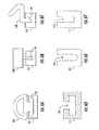
- channel 112 and the bumper 120 have corresponding dovetail-like shapes (see Figs. 1 and 2 ).
- the channel 112 and the bumper 120 may have corresponding T-shapes (see Figs. 6A and 6D ).
- the channel 112 and the bumper 120 may have corresponding kerf-shapes produced, for example, by extruding or cutting the saw-tooth like shape (see Figs. 6B and 6E ), where a kerf is a divergence between the teeth that protrude left-and-right. Any suitable shape may be utilized, provided the bumper 120 may be mounted within the channel 112 via a friction fit.
- the mechanical fit of the bumper 120 to the frame 111 allows for the bumper 120 to be coupled to the frame 111 when the shower door 110 is being assembled. Specifically, to install the bumper 120, the bumper 120 is slid/installed into the channel 112 of the frame 111. The bumper 120 is coupled to the frame 111 via a mechanical, friction fit to give the appearance that the bumper 120 and the frame 111 are one piece. As a result of the mechanical, friction fit, no screws are required to install the bumper 120. Then, the frame 111 and the bumper 120 are bent into a U-shape when the shower door 110 is fabricated.
- the bumper 120 may be slid/installed into the channel 112 in the frame 111 after the frame 111 is bent into a U-shape when the shower door 110 is fabricated.
- the bumper 120 makes a tight connection to the frame 111 and remains attached to a perimeter of the frame 111, even around 90 degree corner joints. This results in the shower door 110 having a soft, radiused outside edge (see Fig. 4 ), rather than a sharp edge with nearly no radius.
- the bumper 120 and the channel 112 cover one or more corners of the shower door 110. This reduces the possibility of being cut by a corner of the frame 111 and provides a user with a more comfortable interaction with the shower door 110.
- the bumper 120 may be more aesthetically pleasing to the user in that there are no bumpers projecting from the shower wall or a wall jamb 210.
- an aesthetically pleasing sealing assembly for a shower door is provided.
- the sealing assembly places a soft, radiused edge around the shower door frame and may serve as a water barrier.
- a shower door sealing assembly comprises a shower door comprising a frame including a channel disposed at an exterior surface of a perimeter of the frame; and a bumper configured to be received in the channel such that the bumper is integrally mounted to the shower door via a friction fit between the channel and the bumper, wherein the channel and the bumper extend along a length of one or more sides of the shower door configured to abut a wall of a showering enclosure.
- the channel and the bumper further extend along a width of a bottom of the shower door.
- the bumper is formed of a solid, flexible material.
- channel and the bumper have mating dovetail-like shapes.
- channel and the bumper having mating T-shapes.
- the channel and the bumper have mating kerf-shapes.
- the shower door has a radiused perimeter.
- the bumper is provided at sides of the shower door configured to abut a shower wall and a bottom of the shower door configured to abut a shower floor.
- the bumper is provided at sides of the shower door configured to abut a shower wall.
- the bumper is configured to provide a water-tight seal between portions of the shower door provided with the bumper and surfaces in contact with the portions of the shower door provided with the bumper.
- the bumper is integrally mounted to the shower door via a friction fit without the use of screws.
- the shower door sealing assembly further comprises a wall jamb mounted on a shower wall, the wall jamb configured to contact the bumper when the shower door is in a closed position.
- a method of assembling a shower door sealing assembly comprises sliding a bumper into a channel disposed at an exterior surface of a perimeter of a shower door frame such that the bumper is integrally mounted to the shower door frame; and bending the bumper and the shower door frame into a desired shape to fabricate the shower door, wherein the channel and the bumper extend along a length of one or more sides of the shower door configured to abut a wall of a showering enclosure.
- the channel and the bumper further extend along a width of a bottom of the shower door.
- the bumper is integrally mounted to the shower door via a friction fit without the use of screws.
- sliding the bumper into the channel comprises mating a dovetail-like protrusion of the bumper with a dove-tail like shape of the channel.
- sliding the bumper into the channel comprises mating a T-shaped protrusion of the bumper with a T-shape of the channel.
- sliding the bumper into the channel comprises mating a kerf-shaped protrusion of the bumper with a kerf-shape of the channel.
- the shower door has a radiused perimeter.
- bending the bumper and the shower door frame into the desired shape for fabrication the shower door comprises providing the bumper at sides of the shower door configured to abut a shower wall and a bottom of the shower door configured to abut a shower floor.
- bending the bumper and the shower door frame into the desired shape for fabrication the shower door comprises providing the bumper at sides of the shower door configured to abut a shower wall.
- the method further comprises forming a water-tight seal by contacting portions of the shower door provided with the bumper with surfaces of a showering enclosure.
- attachment means the joining of two members directly or indirectly to one another.
- Such joining may be stationary (e.g., permanent) or moveable (e.g., removable or releasable).
- Such joining may be achieved with the two members or the two members and any additional intermediate members being integrally formed as a single unitary body with one another or with the two members or the two members and any additional intermediate members being attached to one another.
Landscapes
- Health & Medical Sciences (AREA)
- Public Health (AREA)
- Epidemiology (AREA)
- General Health & Medical Sciences (AREA)
- Residential Or Office Buildings (AREA)
- Specific Sealing Or Ventilating Devices For Doors And Windows (AREA)
- Bathtubs, Showers, And Their Attachments (AREA)
Abstract
A shower door sealing assembly includes a shower door and a bumper. The shower door includes a frame having a channel disposed at an exterior surface of a perimeter of the frame. The bumper is configured to be received in the channel such that the bumper is coupled to the shower door via a friction fit between the channel and the bumper. The channel and the bumper extend along a length of one or more sides of the shower door configured to abut a wall of a showering enclosure or other door assembly component. The bumper is configured to provide a water-tight seal between portions of the shower door along which the bumper extends and surfaces of the showering enclosure or other door assembly components.
Description
- This application claims the benefit of
U.S. Provisional Application No. 61/785,560 filed on March 14, 2013 - The present application relates generally to the field of shower doors. More specifically, the present application relates to a bumper that is mechanically coupled to a shower door's frame.
- This section is intended to provide a background or context to the invention recited in the claims. The description herein may include concepts that could be pursued, but are not necessarily ones that have been previously conceived or pursued. Therefore, unless otherwise indicated herein, what is described in this section is not prior art to the description and claims in this application and is not admitted to be prior art by inclusion in this section.
- Shower doors must be relatively watertight to prevent water damage and to keep water from spraying or leaking out during a shower. Conventional shower doors may include a watertight seal formed by applying silicone caulk on an inside and/or an outside of the edges of the shower door's wall jambs. A seal applied to the door's edge, may also form the watertight seal, with or without the use of a wall jamb. Alternatively, a seal applied to a wall jamb may also form the watertight seal.
- In order to prevent the shower door from slamming shut, bumpers are often installed within a wall jamb, but may also be locally applied to the shower door. The bumpers serve as a stopper that prevents the shower door from hitting the wall jamb. Bumpers may not be aesthetically pleasing, as they protrude from the shower wall, wall jamb, or shower door. In addition, bumpers may fall off, crack or become discolored over time.
- An exemplary embodiment relates to a shower door sealing assembly including a shower door and a bumper. The shower door includes a frame having a channel disposed at an exterior surface of a perimeter of the frame. The bumper is configured to be received in the channel such that the bumper is coupled to the shower door via a friction fit between the channel and the bumper. The channel and the bumper extend along a length of one or more sides of the shower door configured to abut a wall of a showering enclosure. The bumper may be configured to provide a water-tight seal between portions of the shower door along which the bumper extends and surfaces of the showering enclosure or other door assembly components.
- Another exemplary embodiment relates to a method of assembling a shower door sealing assembly. A bumper is slid into a channel disposed at an exterior surface of a perimeter of a shower door frame such that the bumper is coupled to the shower door frame. The channel and the bumper extend along a length of one or more sides of the shower door configured to abut a wall of a showering enclosure or a wall jamb disposed on a wall of a showering enclosure.
- Another exemplary embodiment relates to a shower door sealing assembly as defined in claim 1. Optional features of the shower door sealing assembly are defined in claims 2 to 15.
- Additional features, advantages, and embodiments of the present disclosure may be set forth from consideration of the following detailed description, drawings, and claims. Moreover, it is to be understood that both the foregoing summary of the present disclosure and the following detailed description are exemplary and intended to provide further explanation without further limiting the scope of the present disclosure claimed.
- The accompanying drawings, which are included to provide further understanding of the invention, are incorporated in and constitute a part of this specification, illustrate embodiments of the present disclosure and together with the detailed description serve to explain the principles of the present disclosure. No attempt is made to show structural details of the present disclosure in more detail than may be necessary for a fundamental understanding of the present disclosure and the various ways in which it may be practiced.
-
Fig. 1 is a front view of a shower door sealing assembly including a shower door and a bumper that is mechanically coupled to a shower door frame. -
Fig. 2 is a side cross-sectional view of the shower door ofFig. 1 along the line A-A. -
Fig. 3 is a side-cross sectional view of a detail A illustrating the shower door and the bumper ofFig. 1 . -
Fig. 4 is a top view of the shower door having the bumper ofFig. 1 . -
Fig. 5 is an exploded top view of the shower door having the bumper ofFig. 1 . -
Figs. 6A-6F are top views of alternative embodiments of shapes for shower door seals formed by a mating of a shower door frame and a bumper, and the geometry required to mate the shower door frame and the coupled bumper. -
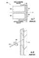
Fig. 7 is a top view of a first embodiment of a conventional bumper known in the art. -
Fig. 8 is an illustration of a method of installing the conventional bumper ofFig. 7 . - Before turning to the figures, which illustrate the exemplary embodiments in detail, it should be understood that the present disclosure is not limited to the details or methodology set forth in the description or illustrated in the figures. It should also be understood that the terminology is for the purpose of description only and should not be regarded as limiting. An effort has been made to use the same or like reference numbers throughout the drawings to refer to the same or like parts.
- Referring to
Fig. 7 , an embodiment illustrating an example of a conventional showerdoor sealing assembly 200 is shown, in which theassembly 200 includes awall jamb 210, abumper 220 andshower door panels 230. Thewall jamb 210 is a rigid extrusion, asymmetrical about a centerline CL. Aleg 211 of thewall jamb 210 located towards an outside of the showering enclosure is longer than aleg 212 located towards an inside of the showering enclosure. Thebumper 220 may be placed locally at a wall connection where thewall jamb 210 is anchored to a wall, or at other points along the wall jamb's length (not illustrated), to prevent theshower door panels 230 from contacting thewall jamb 210 in order to prevent damage to theshower door panels 230. Water is contained within the showering enclosure by an overlap of thewall jamb legs shower door panels 230. In such a configuration,shower door panels 230 that are disposed closer together, disposed closer to thewall jamb 210, and are more overlapped by thelegs wall jamb 200 provide better water containment. - Referring now to
Fig. 8 , thebumper 220 may be mounted on thewall jamb 210 to provide cushioning for the shower door as it closes. Conventionally, asingle bumper 220 is placed locally at a middle of the shower door's opening height or a pair ofbumpers 220 is placed at a top and a bottom of both sides of the shower door's opening. If awall jamb 210 is used, as illustrated inFig. 8 , thebumper 220 is typically installed using thesame screws 213 that attach thewall jamb 210 to the wall. Alternatively, thebumper 220 may be chemically adhered to the edges of theshower door panels 230 or attached to theshower door panels 230 with screws (not illustrated) or with localized friction fits. - Referring generally to
Figs. 1-6F , an exemplary embodiment relates to a bumper that is mechanically coupled to a shower door's frame. The bumper is slid/installed into a channel in the shower door frame before the bumper and frame are bent into a U-shape when the shower door is fabricated. Alternatively, the bumper may be slid/installed into the channel in the shower door frame after the shower door frame is bent into a U-shape when the shower door is fabricated. The channel allows the bumper to make a tight connection to the shower door frame and remain attached to the shower door frame's perimeter, even around 90 degree corner joints. This results in the shower door frame having a soft, radiused outside edge rather than a sharp edge with nearly no radius, reducing the possibility of being cut by the corner of the shower door frame. - Referring to the figures more particularly, as illustrated in
Figs. 1-3 , an exemplary embodiment of a showerdoor sealing assembly 100 includes ashower door 110 and abumper 120. Theshower door 110 includes aframe 111 having achannel 112, disposed at an exterior surface of theshower door 110, along a perimeter of theshower door 110. In an exemplary embodiment, theshower door 110 further includes aglass panel 113 disposed within theframe 111 and connected to theframe 111 via aglazing gasket 114. In other embodiments, thepanel 113 may be comprised of other materials such as plexiglass or plastic. - The
channel 112 extends along a length of one or more sides of theshower door 110. For example, thechannel 112 may extend along a length of one or more sides of theshower door 110 configured to abut a wall of a showering enclosure. Alternatively, thechannel 112 may extend along a length of one or more sides of theshower door 110 configured to abut a wall of the showering enclosure and along a width of a bottom of the shower door 110 (i.e., a side of theshower door 110 configured to abut a floor of the showering enclosure). Thechannel 112 preferably extends along an entire length of either side and the bottom of theshower door 110 in which it is provided. Thechannel 112 may be symmetrical or asymmetrical (see e.g.,Figs. 5 and6A-6F ) with respect to a horizontal or vertical center line of thechannel 112. - In an exemplary embodiment, the
bumper 120 is made of a solid, flexible material such as vinyl or rubber having some "give" to it to absorb the impact of theshower door 110 slamming against a wall (not illustrated) of a showering enclosure. Thus, the showerdoor sealing assembly 100 may also be an impact absorption assembly. The solid, flexible material may also dampen the sound of theshower door 110 slamming against a wall (not illustrated) of the showering enclosure. Thebumper 120 extends along a length of one or more sides of theshower door 110. For example, thebumper 120 may extend along a length of one or more sides of theshower door 110 configured to abut a wall of the showering enclosure. Alternatively, thebumper 120 may extend along a length of one or more sides of theshower door 110 configured to abut a wall of the showering enclosure and along a width of a bottom of the shower door 110 (i.e., a side of theshower door 110 configured to abut a floor of the showering enclosure) or other door assembly components. Thebumper 120 preferably extends along an entire length of each side of theshower door 110 in which it is provided. Thebumper 120 and thechannel 112 extend along a same length of theshower door 110. - The sole means of water containment along vertical edges of the
shower door 110 may be provided by thebumper 120. Alternatively, thebumper 120 may also be used with alternative components to provide a water-tight seal. For example, thebumper 120 may be used in conjunction with awall jamb 210, as illustrated inFigs. 7 and 8 , but thewall jamb 210 is not required. In one embodiment, thewall jamb 210 is mounted on a wall of the showering enclosure and is configured to contact and receive thebumper 120 when theshower door 110 is in a closed position. Any knownwall jamb 210 may be utilized. - Referring now to
Figs. 4 and 5 , thechannel 112 and thebumper 120 are mating parts having corresponding shapes and sizes. Specifically, thebumper 120 includes aprotrusion 121 corresponding in shape and size to thechannel 112. Like thechannel 112, theprotrusion 121 may be symmetrical or asymmetrical (see e.g.,Figs. 5 and6A-6C ) with respect to a horizontal or vertical center line of theprotrusion 121. In an exemplary embodiment,channel 112 and thebumper 120 have corresponding dovetail-like shapes (seeFigs. 1 and 2 ). In another embodiment, thechannel 112 and thebumper 120 may have corresponding T-shapes (seeFigs. 6A and 6D ). In yet another embodiment, thechannel 112 and thebumper 120 may have corresponding kerf-shapes produced, for example, by extruding or cutting the saw-tooth like shape (seeFigs. 6B and 6E ), where a kerf is a divergence between the teeth that protrude left-and-right. Any suitable shape may be utilized, provided thebumper 120 may be mounted within thechannel 112 via a friction fit. - The mechanical fit of the
bumper 120 to theframe 111 allows for thebumper 120 to be coupled to theframe 111 when theshower door 110 is being assembled. Specifically, to install thebumper 120, thebumper 120 is slid/installed into thechannel 112 of theframe 111. Thebumper 120 is coupled to theframe 111 via a mechanical, friction fit to give the appearance that thebumper 120 and theframe 111 are one piece. As a result of the mechanical, friction fit, no screws are required to install thebumper 120. Then, theframe 111 and thebumper 120 are bent into a U-shape when theshower door 110 is fabricated. Alternatively, thebumper 120 may be slid/installed into thechannel 112 in theframe 111 after theframe 111 is bent into a U-shape when theshower door 110 is fabricated. When thebumper 120 is disposed in thechannel 112, thebumper 120 makes a tight connection to theframe 111 and remains attached to a perimeter of theframe 111, even around 90 degree corner joints. This results in theshower door 110 having a soft, radiused outside edge (seeFig. 4 ), rather than a sharp edge with nearly no radius. In an exemplary embodiment, thebumper 120 and thechannel 112 cover one or more corners of theshower door 110. This reduces the possibility of being cut by a corner of theframe 111 and provides a user with a more comfortable interaction with theshower door 110. In addition, thebumper 120 may be more aesthetically pleasing to the user in that there are no bumpers projecting from the shower wall or awall jamb 210. - According to the embodiments described above, an aesthetically pleasing sealing assembly for a shower door is provided. The sealing assembly places a soft, radiused edge around the shower door frame and may serve as a water barrier.
- According to an exemplary embodiment, a shower door sealing assembly comprises a shower door comprising a frame including a channel disposed at an exterior surface of a perimeter of the frame; and a bumper configured to be received in the channel such that the bumper is integrally mounted to the shower door via a friction fit between the channel and the bumper, wherein the channel and the bumper extend along a length of one or more sides of the shower door configured to abut a wall of a showering enclosure.
- It may be that the channel and the bumper further extend along a width of a bottom of the shower door.
- It may be that the bumper is formed of a solid, flexible material.
- It may be that the channel and the bumper have mating dovetail-like shapes.
- It may be that the channel and the bumper having mating T-shapes.
- It may be that the channel and the bumper have mating kerf-shapes.
- It may be that when the bumper is integrally mounted to the shower door, the shower door has a radiused perimeter.
- It may be that the bumper is provided at sides of the shower door configured to abut a shower wall and a bottom of the shower door configured to abut a shower floor.
- It may be that the bumper is provided at sides of the shower door configured to abut a shower wall.
- It may be that the bumper is configured to provide a water-tight seal between portions of the shower door provided with the bumper and surfaces in contact with the portions of the shower door provided with the bumper.
- It may be that the bumper is integrally mounted to the shower door via a friction fit without the use of screws.
- It may be that the shower door sealing assembly further comprises a wall jamb mounted on a shower wall, the wall jamb configured to contact the bumper when the shower door is in a closed position.
- According to another exemplary embodiment, a method of assembling a shower door sealing assembly comprises sliding a bumper into a channel disposed at an exterior surface of a perimeter of a shower door frame such that the bumper is integrally mounted to the shower door frame; and bending the bumper and the shower door frame into a desired shape to fabricate the shower door, wherein the channel and the bumper extend along a length of one or more sides of the shower door configured to abut a wall of a showering enclosure.
- It may be that the channel and the bumper further extend along a width of a bottom of the shower door.
- It may be that the bumper is integrally mounted to the shower door via a friction fit without the use of screws.
- It may be that sliding the bumper into the channel comprises mating a dovetail-like protrusion of the bumper with a dove-tail like shape of the channel.
- It may be that sliding the bumper into the channel comprises mating a T-shaped protrusion of the bumper with a T-shape of the channel.
- It may be that sliding the bumper into the channel comprises mating a kerf-shaped protrusion of the bumper with a kerf-shape of the channel.
- It may be that when the bumper is integrally mounted to the shower door, the shower door has a radiused perimeter.
- It may be that bending the bumper and the shower door frame into the desired shape for fabrication the shower door comprises providing the bumper at sides of the shower door configured to abut a shower wall and a bottom of the shower door configured to abut a shower floor.
- It may be that bending the bumper and the shower door frame into the desired shape for fabrication the shower door comprises providing the bumper at sides of the shower door configured to abut a shower wall.
- It may be that the method further comprises forming a water-tight seal by contacting portions of the shower door provided with the bumper with surfaces of a showering enclosure.
- As utilized herein, the terms "approximately," "about," "substantially", and similar terms are intended to have a broad meaning in harmony with the common and accepted usage by those of ordinary skill in the art to which the subject matter of this disclosure pertains. It should be understood by those of skill in the art who review this disclosure that these terms are intended to allow a description of certain features described and claimed without restricting the scope of these features to the precise numerical ranges provided. Accordingly, these terms should be interpreted as indicating that insubstantial or inconsequential modifications or alterations of the subject matter described and claimed are considered to be within the scope of the invention as recited in the appended claims.
- It should be noted that the term "exemplary" as used herein to describe various embodiments is intended to indicate that such embodiments are possible examples, representations, and/or illustrations of possible embodiments (and such term is not intended to connote that such embodiments are necessarily extraordinary or superlative examples).
- The terms "attached," "coupled," "connected," and the like as used herein mean the joining of two members directly or indirectly to one another. Such joining may be stationary (e.g., permanent) or moveable (e.g., removable or releasable). Such joining may be achieved with the two members or the two members and any additional intermediate members being integrally formed as a single unitary body with one another or with the two members or the two members and any additional intermediate members being attached to one another.
- References herein to the positions of elements (e.g., "top," "bottom," "above," "below," etc.) are merely used to describe the orientation of various elements in the FIGURES. It should be noted that the orientation of various elements may differ according to other exemplary embodiments, and that such variations are intended to be encompassed by the present disclosure.
- It is important to note that the construction and arrangement of the shower door sealing assembly as shown and/or described in the various exemplary embodiments is illustrative only. Although only a few embodiments have been described in detail in this disclosure, those skilled in the art who review this disclosure will readily appreciate that many modifications are possible (e.g., variations in sizes, dimensions, structures, shapes and proportions of the various elements, values ofparameters, mounting arrangements, use of materials, colors, orientations, etc.) without materially departing from the novel teachings and advantages of the subject matter described herein. For example, elements shown as integrally formed may be constructed of multiple parts or elements, the position of elements may be reversed or otherwise varied, and the nature or number of discrete elements or positions may be altered or varied. The order or sequence of any process or method steps may be varied or re-sequenced according to alternative embodiments. Other substitutions, modifications, changes and omissions may also be made in the design, operating conditions and arrangement of the various exemplary embodiments without departing from the scope of the present invention.
Claims (15)
- A shower door sealing assembly comprising:a shower door comprising a frame including a channel disposed at an exterior surface of a perimeter of the frame; anda bumper configured to be received in the channel such that the bumper is coupled to the shower door via a friction fit between the channel and the bumper,wherein the channel and the bumper extend along a length of one or more sides of the shower door configured to abut a wall of a showering enclosure or other door assembly component, andwherein the bumper is configured to provide a water-tight seal between portions of the shower door along which the bumper extends and surfaces of the showering enclosure or other door assembly component.
- The shower door sealing assembly according to any of the preceding claims, wherein the channel and the bumper further extend along a width of a bottom of the shower door configured to abut a floor of the showering enclosure or other door assembly component.
- The shower door sealing assembly according to any of the preceding claims, wherein the bumper includes a protrusion configured to mate with the channel, the protrusion and the channel having corresponding shapes and sizes.
- The shower door sealing assembly according to claim 3, wherein both the protrusion of the bumper and the channel are dovetail-shaped.
- The shower door sealing assembly according to claim 3, wherein both the protrusion of the bumper and the channel are T-shaped.
- The shower door sealing assembly according to claim 3, wherein both the protrusion of the bumper and the channel are created using a saw such that the shapes of the protrusion and the channel include diverging teeth.
- The shower door sealing assembly according to any of the preceding claims, wherein when the bumper is coupled to the shower door frame, the shower door sealing assembly has an at least partially radiused perimeter.
- The shower door sealing assembly according to any of the preceding claims, wherein the bumper and the channel cover at least one corner of the shower door.
- The shower door sealing assembly according to any of the preceding claims, wherein the bumper is formed of a solid, flexible material.
- The shower door sealing assembly according to any of the preceding claims, wherein the bumper is formed of vinyl or rubber.
- The shower door sealing assembly according to any of the preceding claims, wherein the bumper is coupled to the shower door without the use of screws.
- The shower door sealing assembly according to any of the preceding claims, further comprising a wall jamb mounted on the wall of the showering enclosure, the wall jamb configured to receive the bumper when the shower door is in a closed position and provide a water-tight seal.
- The shower door sealing assembly according to any of the preceding claims, wherein the bumper is a sole means of water containment along the one or more sides of the shower door configured to abut the wall of the showering enclosure or other door assembly component.
- The shower door sealing assembly according to any of the preceding claims, wherein the bumper is received by the channel prior to bending the shower door frame into a desired shape to fabricate the shower door.
- The shower door sealing assembly according to any of the preceding claims, wherein the bumper is received by the channel after bending the shower door frame into a desired shape to fabricate the shower door.
Applications Claiming Priority (1)
| Application Number | Priority Date | Filing Date | Title |
|---|---|---|---|
| US201361785560P | 2013-03-14 | 2013-03-14 |
Publications (1)
| Publication Number | Publication Date |
|---|---|
| EP2778335A1 true EP2778335A1 (en) | 2014-09-17 |
Family
ID=50238310
Family Applications (1)
| Application Number | Title | Priority Date | Filing Date |
|---|---|---|---|
| EP14158980.4A Withdrawn EP2778335A1 (en) | 2013-03-14 | 2014-03-11 | Shower door bumper |
Country Status (3)
| Country | Link |
|---|---|
| US (2) | US20140259366A1 (en) |
| EP (1) | EP2778335A1 (en) |
| CN (1) | CN104047501A (en) |
Families Citing this family (7)
| Publication number | Priority date | Publication date | Assignee | Title |
|---|---|---|---|---|
| US9980614B2 (en) * | 2016-08-17 | 2018-05-29 | Liberty Hardware Mfg. Corp. | Base member for a shower door assembly |
| CN110578455B (en) * | 2018-06-07 | 2020-11-20 | 江西凡达建材有限公司 | A door leaf bottom sealing member and its manufacturing process |
| JP7063740B2 (en) * | 2018-06-18 | 2022-05-09 | 日本板硝子株式会社 | Vacuum glass panel |
| US11877707B2 (en) | 2020-07-24 | 2024-01-23 | Liberty Hardware Mfg. Corp. | Shower door assembly |
| US12564294B2 (en) | 2020-07-24 | 2026-03-03 | Liberty Hardware Mfg. Corp. | Shower door assembly |
| US11655658B2 (en) | 2021-03-04 | 2023-05-23 | Liberty Hardware Mfg. Corp. | Shower door guide assembly |
| US12123249B2 (en) | 2022-03-29 | 2024-10-22 | Aston Global, Inc. | Integrated sliding glass panel bumpers |
Citations (6)
| Publication number | Priority date | Publication date | Assignee | Title |
|---|---|---|---|---|
| US3390486A (en) * | 1966-01-24 | 1968-07-02 | Herbert J. Walters | Pivoting shower door |
| GB2056519A (en) * | 1979-08-10 | 1981-03-18 | Glover E | Foldable shower cubicle |
| US4715072A (en) * | 1985-03-18 | 1987-12-29 | Sudmann Jurgen Peter | Shower barrier |
| US5023965A (en) * | 1989-03-11 | 1991-06-18 | Reichel Guenter | Shower unit panel |
| DE29614322U1 (en) * | 1996-08-21 | 1996-10-24 | Dorma Gmbh & Co Kg | Final profile |
| WO2012037701A1 (en) * | 2010-09-24 | 2012-03-29 | Eku Ag | Shower wall having a sliding door |
Family Cites Families (18)
| Publication number | Priority date | Publication date | Assignee | Title |
|---|---|---|---|---|
| US1944440A (en) | 1929-12-14 | 1934-01-23 | Louis H Lehman | Shower bath stall door, shower bath shield, and the like |
| US2331822A (en) * | 1938-12-06 | 1943-10-12 | Eugene H Zechiel | Folding closure for recess tub shower bath |
| US3213584A (en) * | 1963-07-31 | 1965-10-26 | Standard Products Co | Gaskets |
| US3449770A (en) | 1967-06-22 | 1969-06-17 | Ralph T Casebolt | Drip assembly for shower door |
| US3955789A (en) | 1971-12-30 | 1976-05-11 | Larry Harold Kline | Tube holder |
| US3737921A (en) | 1971-12-30 | 1973-06-12 | Larry Kline | Permanent or mobile splash-guard |
| US3854248A (en) * | 1973-05-21 | 1974-12-17 | L Dayus | Duct access door |
| US4392272A (en) | 1981-02-17 | 1983-07-12 | Ksd Industries, Inc. | Track and panel guide for sliding shower doors or the like |
| US4759087A (en) | 1987-06-08 | 1988-07-26 | Magic American Corporation | Closure device for a shower curtain |
| US4887324A (en) | 1988-07-15 | 1989-12-19 | Cairns H Ross | Curtain retaining apparatus |
| US5337425A (en) | 1992-02-03 | 1994-08-16 | Jane Hill | Shower curtain |
| US6655444B2 (en) | 1997-10-31 | 2003-12-02 | 420820 Ontario Limited | Roll out shower curtain and the use thereof as an advertising display for the hospitality industry |
| US6067672A (en) | 1998-03-09 | 2000-05-30 | Klotz; Ronald E. | Shower curtain closure assembly |
| US6148452A (en) | 1999-05-10 | 2000-11-21 | Kirsopp; Derek | Closure for shower curtains |
| DE10052507A1 (en) * | 2000-10-23 | 2002-04-25 | Queen Sanitaer Produkte Gmbh | Profiled edging for shower partition panel engages U-shaped over edge of panel and forms longitudinal groove open to outside to house sealing profile |
| US6668394B2 (en) | 2001-06-06 | 2003-12-30 | Lionel A. Walpin | Convertible couch bed |
| US7644453B2 (en) | 2005-02-23 | 2010-01-12 | Dyckow Dean W | Shower curtain fastening system |
| CN2797561Y (en) * | 2005-05-24 | 2006-07-19 | 危五祥 | Apparatus for connecting, sealing and positioning bathroom door and screen |
-
2014
- 2014-03-11 EP EP14158980.4A patent/EP2778335A1/en not_active Withdrawn
- 2014-03-12 CN CN201410088967.XA patent/CN104047501A/en active Pending
- 2014-03-13 US US14/208,859 patent/US20140259366A1/en not_active Abandoned
-
2016
- 2016-12-15 US US15/380,618 patent/US10213059B2/en active Active
Patent Citations (6)
| Publication number | Priority date | Publication date | Assignee | Title |
|---|---|---|---|---|
| US3390486A (en) * | 1966-01-24 | 1968-07-02 | Herbert J. Walters | Pivoting shower door |
| GB2056519A (en) * | 1979-08-10 | 1981-03-18 | Glover E | Foldable shower cubicle |
| US4715072A (en) * | 1985-03-18 | 1987-12-29 | Sudmann Jurgen Peter | Shower barrier |
| US5023965A (en) * | 1989-03-11 | 1991-06-18 | Reichel Guenter | Shower unit panel |
| DE29614322U1 (en) * | 1996-08-21 | 1996-10-24 | Dorma Gmbh & Co Kg | Final profile |
| WO2012037701A1 (en) * | 2010-09-24 | 2012-03-29 | Eku Ag | Shower wall having a sliding door |
Also Published As
| Publication number | Publication date |
|---|---|
| CN104047501A (en) | 2014-09-17 |
| US20170095124A1 (en) | 2017-04-06 |
| US20140259366A1 (en) | 2014-09-18 |
| US10213059B2 (en) | 2019-02-26 |
Similar Documents
| Publication | Publication Date | Title |
|---|---|---|
| US10213059B2 (en) | Method of assembling a shower door sealing assembly | |
| AU2013100819A4 (en) | Door assembly | |
| JP7822824B2 (en) | Frame and fittings | |
| GB2617269A (en) | Apparatus and method for installing a closure in a building | |
| US9492038B2 (en) | Shower door seal system | |
| KR101212248B1 (en) | Door and doorframe, window and windowframe for preventing injury of hand | |
| JP2015203236A (en) | Joinery | |
| JP4697976B2 (en) | Renovation sash frame mounting structure | |
| JP7253917B2 (en) | bathroom fittings | |
| US20170065133A1 (en) | Shower Door Leveler | |
| RU2094241C1 (en) | Vehicle door sill sealing strip | |
| JP6894257B2 (en) | Joinery | |
| KR101903795B1 (en) | Window having a slim frame | |
| JP2023137336A (en) | Water cut-off device | |
| JP5180812B2 (en) | Sash window frame device for repair | |
| JP2005047693A (en) | Door opening and closing part structure of elevator hall | |
| US20250160580A1 (en) | Four-way pivot door | |
| JP6862293B2 (en) | Gate unit | |
| JP7671221B2 (en) | Frame components, frame materials and fittings mounting structure | |
| GB2482109A (en) | A seal for a shower enclosure | |
| JP7820972B2 (en) | Panel body fitting structure | |
| TW201617512A (en) | Watertight structure of mating part and door/window | |
| GB2538727A (en) | Window assembly | |
| JP7150503B2 (en) | Mounting structure of metal siding | |
| JP2024012991A (en) | Fixture |
Legal Events
| Date | Code | Title | Description |
|---|---|---|---|
| 17P | Request for examination filed |
Effective date: 20140311 |
|
| AK | Designated contracting states |
Kind code of ref document: A1 Designated state(s): AL AT BE BG CH CY CZ DE DK EE ES FI FR GB GR HR HU IE IS IT LI LT LU LV MC MK MT NL NO PL PT RO RS SE SI SK SM TR |
|
| AX | Request for extension of the european patent |
Extension state: BA ME |
|
| PUAI | Public reference made under article 153(3) epc to a published international application that has entered the european phase |
Free format text: ORIGINAL CODE: 0009012 |
|
| STAA | Information on the status of an ep patent application or granted ep patent |
Free format text: STATUS: THE APPLICATION IS DEEMED TO BE WITHDRAWN |
|
| 18D | Application deemed to be withdrawn |
Effective date: 20150318 |