EP2778281B1 - Heat exchanger for condensation in clothes drying and clothes drying system and clothes dryer - Google Patents
Heat exchanger for condensation in clothes drying and clothes drying system and clothes dryer Download PDFInfo
- Publication number
- EP2778281B1 EP2778281B1 EP12847897.1A EP12847897A EP2778281B1 EP 2778281 B1 EP2778281 B1 EP 2778281B1 EP 12847897 A EP12847897 A EP 12847897A EP 2778281 B1 EP2778281 B1 EP 2778281B1
- Authority
- EP
- European Patent Office
- Prior art keywords
- air
- heat exchanger
- air channel
- heat recovery
- clothes
- Prior art date
- Legal status (The legal status is an assumption and is not a legal conclusion. Google has not performed a legal analysis and makes no representation as to the accuracy of the status listed.)
- Active
Links
Images




Classifications
-
- D—TEXTILES; PAPER
- D06—TREATMENT OF TEXTILES OR THE LIKE; LAUNDERING; FLEXIBLE MATERIALS NOT OTHERWISE PROVIDED FOR
- D06F—LAUNDERING, DRYING, IRONING, PRESSING OR FOLDING TEXTILE ARTICLES
- D06F58/00—Domestic laundry dryers
- D06F58/20—General details of domestic laundry dryers
- D06F58/22—Lint collecting arrangements
-
- D—TEXTILES; PAPER
- D06—TREATMENT OF TEXTILES OR THE LIKE; LAUNDERING; FLEXIBLE MATERIALS NOT OTHERWISE PROVIDED FOR
- D06F—LAUNDERING, DRYING, IRONING, PRESSING OR FOLDING TEXTILE ARTICLES
- D06F58/00—Domestic laundry dryers
- D06F58/20—General details of domestic laundry dryers
- D06F58/24—Condensing arrangements
-
- F—MECHANICAL ENGINEERING; LIGHTING; HEATING; WEAPONS; BLASTING
- F26—DRYING
- F26B—DRYING SOLID MATERIALS OR OBJECTS BY REMOVING LIQUID THEREFROM
- F26B21/00—Arrangements for supplying or controlling air or other gases for drying solid materials or objects
- F26B21/30—Controlling, e.g. regulating, parameters of gas supply
- F26B21/33—Humidity
- F26B21/333—Humidity by condensing the moisture in the drying medium, which may be recycled, e.g. using a heat pump cycle
-
- D—TEXTILES; PAPER
- D06—TREATMENT OF TEXTILES OR THE LIKE; LAUNDERING; FLEXIBLE MATERIALS NOT OTHERWISE PROVIDED FOR
- D06F—LAUNDERING, DRYING, IRONING, PRESSING OR FOLDING TEXTILE ARTICLES
- D06F58/00—Domestic laundry dryers
- D06F58/20—General details of domestic laundry dryers
- D06F58/206—Heat pump arrangements
Definitions
- the invention relates to a heat exchanger for condensation in clothes drying as defined by the preamble portion of claim 1. Further, the invention relates to a clothes dryer and clothes drying system including such a heat exchanger.
- the apparatus for producing hot air almost adopts the way of heating air by heater.
- the existing electro-thermal clothes dryer usually takes the heating strip/pipe as the heat source.
- This kind of product has high energy consumption, long drying time and poor security.
- heat pump clothes dryer which employs heat pump system, is developed. This kind of clothes dryer strengthens the cyclic utilization of heat, improves the utilization efficiency of heat and lowers the power consumption.
- the heat pump type clothes dryer apparatus are provided with the following air circulation channels: the air heated by the condenser in heat pump circulation system is sent into the drying chamber filling with clothes, and the air after absorbing moisture of clothes is then sent back to the evaporator for desiccation, after that, the air is again heated by the condenser and sent to the drying chamber.
- the energy consumption of the heat pump type clothes dryer has decreased, the drying speed is not improved, the time required for drying process is still long. It usually takes 2 to 3 hours to dry 7-8KG clothes.
- people have taken various ways to achieve this purpose.
- the way that the clothes dryer adopted is to elevate temperature, enhance the ventilation of surface, and increase the heat-exchange surface. Although these ways have been used, the energy consumption and drying time are still high in the drying process. And if it proceeds to drying clothes under the high temperature, the fabric can be damaged, and may be prone to wrinkle and shrink.
- Chinese patent document CN1936160B discloses a clothes drying apparatus in which the heat pump generating the drying air circulating between the drying chamber and the heat pump achieves stable operation.
- the air heated by the heater in heat pump is sent into the bucket which serves as drying chamber, and then the air emitted from the bucket returns back to the heat pump through the filter unit, and sent to the heater after being dehumidified by the heat absorber as a result of forming an air circulation channels.
- the filter unit is provided with a lint flushing filter and pipelines communicating with air outlet and air inlet.
- the drying circulatory system of the existing clothes dryer utilizes the condensing heat exchanger equipped with cold air as the cooling medium, which is applied to clothes dryer or integral washing-drying machine.
- the one is to utilize the outside cool air to convert the hot and humid air generated in drying process into hypothermal and low-humidity air and recycle it; the other one is to exchange the hot and humid air generated in drying process with the outside hypothermal and low-humidity air and exhaust it, and then send the preheated outside air after exchanging inside for recycling.
- These patterns have their disadvantages.
- As for the former one a large amount of outside cooling air is needed, and a relatively large quality of heat is taken away, thus the air reentering in the drying circulation needs to be heated with much energy.
- the moisture in the moist air cannot be condensed totally, and there's still plenty of moisture access to the environment and influence the comfort level of the environment.
- the drying fan drives the drying air to flow along with the drying route, heating strip/pipe starts to heat, the hot air enters into the washing tub/clothes drying tub, in which the temperature of the clothes and moisture rises.
- the moisture evaporates into water vapor and then enters into the condensing heat exchanger by lint flushing filter.
- the condensate fan drives the outside air to exchange heat with the internal air.
- the internal hot and humid air cools down, the water vapor condenses into liquid water, and the hot and humid air transforms into dry and hypothermal air which then is sent to heat strip/pipe by drying fan for being heated and drying circularly clothes.
- the aforesaid condensing heat exchanger is made of the sheet metals, which are formed the drying wind channels and interlaced condensing wind channels by welding procedure.
- Such processing technology of condenser is quite complicated and the condenser cannot be processed and manufactured according to washing machine structure arbitrarily, and it costs high.
- a heat exchanger for condensation in clothes drying according to the preamble portion of claim 1 is known from EP 2 169 107 A1 .
- a spraying device is arranged at an outlet of the heat exchanger for spraying water towards the heat exchanger to thereby flush lint.
- the invention aims at providing a simple-structured and low-cost heat exchanger for condensation in clothes drying.
- the invention provides a clothes drying system and clothes dryer with the heat exchanger.
- the condensed dry air is preheated by the residual heat of the hot and humid air exchanging heat with clothes, and then is heated, so as to raise the clothes drying efficiency, save electric energy and time.
- the heat exchanger and drying system of this invention may also be applied to an integral washing-drying machine.
- the heat exchanger may be made of plastic film, a non-metallic material, with a thickness of 0.05 ⁇ 1.5mm. Compared with metallic heat-exchanger, the exchanger of the invention has lower production cost while higher heat exchanger efficiency. Besides, plastic film, as the material of heat exchanger, is easier to be manufactured and assembled in accordance with the various dying power of clothes dryers or integral washing-drying machines. Moreover, clothes dryers or integral washing-drying machines with the heat exchanger are much lighter, which is more convenient and cost-saving for transportation.
- the drying system and clothes dryer of the invention comprise the heat exchanger, the water collection box and the residual heat recovery device which comprises two air channels, namely, the hot and humid air channel and the residual heat recovery air channel.
- the residual heat recovery air channel air condensed through the heat exchanger pre-cools the hot and humid air in the hot and humid air channel from the clothes tub of the clothes dryer. Meanwhile, it also get preheated while absorbing the heat, thus lowering the energy loss of heating the heater of the clothes dry to the drying temperature, enhancing the drying efficiency and saving power.
- precooling function of the residual heat recovery device can also reduce the flow of condensed air outside and the noise of condensate fan.
- the heat exchanger for condensation in clothes drying is installed in a clothes dryer or washing machine having the function of drying.
- the heat exchanger 1 made of plastic film, is an external air-cooled heat exchanger.
- the interior of the heat exchanger comprises two groups of air channels going towards different directions and not communicating with each other, which are respectively a condensing air channel 11 and an external air channel 12.
- Each group of air channel is composed of a plurality of air chambers.
- the air chambers of two groups of air channels are arranged alternately in turn.
- the space between neighboring air chambers of the same group of air channel is an air chamber of the other group of air channel, and all of them are made of interval plastic film walls.
- a condensate fan 15 (see Figures 5 and 6 ) is set on one end of the external air channel 12, and the other end directly leads to the outside.
- the hot and humid air is put in through one end of the condensing air channel 11, and the condensed air and water are exhausted through the other end.
- the condensing air channel 11 is composed of air chambers 13.
- the external air channel 12 is composed of air chambers 14.
- the space between neighboring air chambers 13 of the condensing air channel 11 is an air chamber 14 of the external air channel 12.
- the thickness L of the plastic film is in the range of 0.05mm to 1.5mm; preferably, the thickness of the plastic film is in the rang of 0.08mm to 0.8mm; more preferably, the thickness of the plastic film is in the rang of 0.1mm to 0.5mm.
- the embodiment adopts the plastic film with the thickness of 0.1mm.
- the shape of the cross-section of the air chamber is not limited to rectangular, circle or elliptic type. Various corrugated shape for the drop of condensate water can also be set on the wall of the air chamber, or combination of the aforesaid shapes.
- the plastic film of the present invention has heat resistance, for example, polyimide film, which is undistorted even at a temperature of 150°C.
- the plastic film in the embodiment is polyethylene film with a distortion temperature of 80-100°C.
- a mechanism for flushing lint is comprised.
- the mechanism for flushing lint is arranged at one end of a hot and humid air inlet 16 of the condensing air channel 11 of the heat exchanger 1.
- the mechanism for flushing lint included a flushing valve connection 82 communicated with the exterior, a flushing passageway 83 communicating to the flushing valve connection and being set annularly along the air inlet for the hot and humid air of the heat exchanger, and a flushing mouth 81 set along the edge of the flushing passageway for flushing water towards the air channel for the hot and humid air in the inside of the heat exchanger.
- the foregoing heat exchanger may be installed inside a integral washing-drying machine (see Figure 5 ) or a clothes dryer (see Figure 7 ), which comprises a clothes tub 2, an air outlet 21, a filter 3, a heat exchanger 1, a water collection box 4, a drying fan 5, a heating unit 6 and an air inlet 22.
- the air outlet 21 communicates with the heat exchanger 1 which communicates with the water collection box 4; and the water collection box 4 communicates with the air inlet 22.
- the filter 3 is arranged between the air outlet 22 and the heat exchanger 1, and the drying fan 5 and the heating unit 6 are arranged between the water collection box 4 and air inlet 22 in turn.
- the water collection box 4 communicates with the outside through a draining pump 41, and a water level inductive switch 42 for controlling to turn on the draining pump 41 is installed in the water collection box 4.
- the water collection box 4 comprises a water-holding box 43 and a top cover 44 (see Figures 3 and 4 ).
- An inlet 45 communicating with a hot and humid air outlet 17 of the condensing air channel of the heat exchanger and an outlet 46 communicating with the air inlet 22 of the clothes dryer are arranged on the top cover 44.
- the clothes tub 2, the air outlet 21, the filter 3, the drying fan 5, the heat unit 6 and the air inlet 22 all may adopt the designs in prior arts.
- the air inlet and the air outlet are both the air inlet and the air outlet of the clothes tub.
- the heating unit 6 is generally made of heating pipe or heater strip or heating plate.
- the filter 3 is composed of at least one layer of filter net, which is dismountable.
- the hot and humid air from the air outlet of the clothes tub 2 enters the condensing air channel 11 of the heat exchange 1 along the pipeline.
- the external air passed in through the external air channel 12 of the heat exchanger 1 exchanges heat with the hot and humid air in the condensing air channel 11.
- Temperature of the hot and humid air in condensing air channel 11 drops while its relative humidity rises.
- Partial air around the wall of the air chambers gets saturated, and vapors in the air precipitate and flow into the water collection box 4 along with the wall of the air chambers.
- the draining pump 41 is turned on, discharging the condensate water.
- the condensed low-heat and low-humidity air passes through the water collection box 4, and is sent to the heating unit 6 for heating by the drying fan 5, and then reflows into the clothes tub 2 through the air inlet.
- the drying system of this embodiment consists of the heat exchanger 1 of Embodiment 1 or 2 and a residual heat recovery device 7.
- the interior of the residual heat recovery device 7 comprises two groups of air channels, namely, a hot and humid air channel 71 and a residual heat recovery air channel 72.
- the two groups of air channels form a heat exchange structure.
- the hot and humid air channel 71 communicates with the condensing air channel 11, the water collection box 4 and the residual heat recovery air channel 72 in turn through ventilating ducts.
- the residual heat recovery device 7 comprises a shell 70, and a heat exchanger 73 arranged inside the shell.
- the hot and humid air channel 71 and the residual heat recovery air channel 72 are arranged in the heat exchanger 73 in the way of bidirectional cross convection.
- an air inlet 74 of the hot and humid air channel and an air outlet 75 of the residual heat recovery air channel are arranged on the upper of the shell 70, and an air outlet 76 of the hot and humid air channel and an air inlet 77 of the residual heat recovery air channel are arranged on the lower of the shell 70.
- the air inlet 74 and the outlet 76 of the hot air and humid air channel all are arranged on the cross.
- the air outlet 76 of the hot and humid air channel of the residual heat recovery device 7 communicates with the air inlet 16 of the hot and humid air channel of the condensing air channel 11 of the heat exchanger 1, and the air inlet 77 of the residual heat recovery air channel communicates with the outlet 46 of the water collection box 4.
- two groups of heat exchange fins form the hot and humid air channel and the residual heat recovery air channel.
- Each group of the heat exchange fins form a plurality of air channels along the same direction.
- the space between the neighboring air channels of the same group is an air channel of the other group.
- the air channels composed of two groups of heat exchange fins are set by interval, which forms the heat exchange structure with bidirectional cross convection.
- the interior of the heat exchanger 73 is composed of multiple parallel plates. Air channels 78 and 79 are arranged between two adjacent plates. Two group of isolated and crossed air channels are formed by blocking the air channels at intervals along the inlet direction and the outlet direction. Alternatively, in an integral structure, penetrating two groups of two-way crossed air channels 78 and 79. Or the heat exchanger 73 can also adopt the existing plate-interval recuperative heat exchanger.
- the difference from that of Embodiment 3 is that the clothes dryer or the washing-drying machine of the embodiment is arranged the residual heat recovery device 7 on the basis of Embodiment 4.
- the residual heat recovery device 7 is set between the filter 3 and the heat exchanger 1, also between the water collection box 4 and the drying fan 5.
- the hot and humid air channel 71 communicates with the filter 3 and the heat exchanger 1
- the residual heat recovery air channel 72 communicates with the water collection box 4 and the drying fan 5.
- the hot and humid air passes out from the air outlet of the clothes tub 2, and flows through the hot and humid air channel 71 of the residual heat recovery device 7, the heat exchanger 1 and the water collection box 4 successively, then flows through the residual heat recovery air channel 72 of the residual heat recovery device 7.
- it is completed to recover the residual heat.
- the hot and humid air from the air outlet of the clothes tub 2 goes in the hot and humid air channel 71 through the air inlet of the hot and humid air channel 74 of the residual heat recovery device, and is discharged from the air outlet 76 of the hot and humid air channel 76, and then enters the condensing air channel 11 of the heat exchanger 1.
- the external air passed in through the external air channel 12 of the heat exchanger 1 exchanges heat with the hot and humid air in the condensing air channel 11.
- Temperature of the hot and humid air in condensing air channel 11 drops, while its relative humidity rises.
- Partial air around the wall of the air chambers gets saturated, and vapors in the air precipitate and flow into the water collection box 4 along with the wall of the air chambers..
- the draining pump 41 is turned on, discharging the condensate water.
- the condensed low-heat and low-humidity air passes through the water collection box 4, and is sent to the air inlet 77 of the residual heat recovery air channel of the residual heat recovery device, and then goes in the residual heat recovery air channel 72.
- the temperature of the condensed air water decreases while water content decreases.
- the low temperature air getting back to the residual heat recovery device exchanges heat with the hot and humid air inside the hot and humid air channel 71 again.
- the hot and humid air is cool in advance.
- the dry air through the residual heat recovery device 7 heats up before being heated inside the heating unit 6, thus it becomes preheated. Therefore, energy consumption on reheating the air in the drying recycle system is reduced, and the noise generated by condensing air in high flow rate is reduced.
- the filter 3 comprises at least two layers of filter net. And the layer next to the outlet is dismountable and convenient for flushing.
- the heat exchanger made of plastic film is adopted to air-cool the external air, which is efficient and easy to be processed, meanwhile, it is easier to be assembled and installed in accordance with the drying power of the clothes dryer or integral washing-drying machine. Besides, clothes dryer or integral washing-drying machine arranged with such heat exchanger is lighter, more convenient and cost-saving in transportation.
Landscapes
- Engineering & Computer Science (AREA)
- Textile Engineering (AREA)
- Mechanical Engineering (AREA)
- General Engineering & Computer Science (AREA)
- Detail Structures Of Washing Machines And Dryers (AREA)
Description
- The invention relates to a heat exchanger for condensation in clothes drying as defined by the preamble portion of
claim 1. Further, the invention relates to a clothes dryer and clothes drying system including such a heat exchanger. - In the clothes dryer mechanism used for clothes drying machine or laundry dryer, the apparatus for producing hot air almost adopts the way of heating air by heater. The existing electro-thermal clothes dryer usually takes the heating strip/pipe as the heat source. This kind of product has high energy consumption, long drying time and poor security. To reduce energy consumption, heat pump clothes dryer, which employs heat pump system, is developed. This kind of clothes dryer strengthens the cyclic utilization of heat, improves the utilization efficiency of heat and lowers the power consumption.
- The heat pump type clothes dryer apparatus are provided with the following air circulation channels: the air heated by the condenser in heat pump circulation system is sent into the drying chamber filling with clothes, and the air after absorbing moisture of clothes is then sent back to the evaporator for desiccation, after that, the air is again heated by the condenser and sent to the drying chamber.
- Although the energy consumption of the heat pump type clothes dryer has decreased, the drying speed is not improved, the time required for drying process is still long. It usually takes 2 to 3 hours to dry 7-8KG clothes. In order to remove the moisture of clothes in a short time, people have taken various ways to achieve this purpose. The way that the clothes dryer adopted is to elevate temperature, enhance the ventilation of surface, and increase the heat-exchange surface. Although these ways have been used, the energy consumption and drying time are still high in the drying process. And if it proceeds to drying clothes under the high temperature, the fabric can be damaged, and may be prone to wrinkle and shrink.
- Chinese patent document
CN1936160B discloses a clothes drying apparatus in which the heat pump generating the drying air circulating between the drying chamber and the heat pump achieves stable operation. The air heated by the heater in heat pump is sent into the bucket which serves as drying chamber, and then the air emitted from the bucket returns back to the heat pump through the filter unit, and sent to the heater after being dehumidified by the heat absorber as a result of forming an air circulation channels. The filter unit is provided with a lint flushing filter and pipelines communicating with air outlet and air inlet. - The drying circulatory system of the existing clothes dryer utilizes the condensing heat exchanger equipped with cold air as the cooling medium, which is applied to clothes dryer or integral washing-drying machine. There're two main patterns, the one is to utilize the outside cool air to convert the hot and humid air generated in drying process into hypothermal and low-humidity air and recycle it; the other one is to exchange the hot and humid air generated in drying process with the outside hypothermal and low-humidity air and exhaust it, and then send the preheated outside air after exchanging inside for recycling. These patterns have their disadvantages. As for the former one, a large amount of outside cooling air is needed, and a relatively large quality of heat is taken away, thus the air reentering in the drying circulation needs to be heated with much energy. While for the latter one, in the course of emitting the drying air, the moisture in the moist air cannot be condensed totally, and there's still plenty of moisture access to the environment and influence the comfort level of the environment.
- For the clothes dryer or integral washing-drying machine that the cold air is served as the cooling medium, in the drying process, the drying fan drives the drying air to flow along with the drying route, heating strip/pipe starts to heat, the hot air enters into the washing tub/clothes drying tub, in which the temperature of the clothes and moisture rises. The moisture evaporates into water vapor and then enters into the condensing heat exchanger by lint flushing filter. The condensate fan drives the outside air to exchange heat with the internal air. Thus the internal hot and humid air cools down, the water vapor condenses into liquid water, and the hot and humid air transforms into dry and hypothermal air which then is sent to heat strip/pipe by drying fan for being heated and drying circularly clothes.
- The aforesaid condensing heat exchanger is made of the sheet metals, which are formed the drying wind channels and interlaced condensing wind channels by welding procedure. Such processing technology of condenser is quite complicated and the condenser cannot be processed and manufactured according to washing machine structure arbitrarily, and it costs high.
- A heat exchanger for condensation in clothes drying according to the preamble portion of
claim 1 is known fromEP 2 169 107 A1 - The invention aims at providing a simple-structured and low-cost heat exchanger for condensation in clothes drying.
- This technical problem is solved by a heat exchanger comprising the features of
claim 1. Advantageous embodiments are indicated in further claims. Further, the invention provides a clothes drying system and clothes dryer with the heat exchanger. In the process of drying, the condensed dry air is preheated by the residual heat of the hot and humid air exchanging heat with clothes, and then is heated, so as to raise the clothes drying efficiency, save electric energy and time. - The heat exchanger and drying system of this invention may also be applied to an integral washing-drying machine.
- The heat exchanger may be made of plastic film, a non-metallic material, with a thickness of 0.05∼1.5mm. Compared with metallic heat-exchanger, the exchanger of the invention has lower production cost while higher heat exchanger efficiency. Besides, plastic film, as the material of heat exchanger, is easier to be manufactured and assembled in accordance with the various dying power of clothes dryers or integral washing-drying machines. Moreover, clothes dryers or integral washing-drying machines with the heat exchanger are much lighter, which is more convenient and cost-saving for transportation.
- The drying system and clothes dryer of the invention comprise the heat exchanger, the water collection box and the residual heat recovery device which comprises two air channels, namely, the hot and humid air channel and the residual heat recovery air channel. In the residual heat recovery air channel, air condensed through the heat exchanger pre-cools the hot and humid air in the hot and humid air channel from the clothes tub of the clothes dryer. Meanwhile, it also get preheated while absorbing the heat, thus lowering the energy loss of heating the heater of the clothes dry to the drying temperature, enhancing the drying efficiency and saving power. In the meantime, precooling function of the residual heat recovery device can also reduce the flow of condensed air outside and the noise of condensate fan.
- Combining with the drawings below, the embodiments further are described in detail.
-
-
Figure 1 is a schematic drawing of the heat exchanger of anembodiment 1 not belonging to the invention; -
Figure 2 is an A-direction sectional drawing ofFigure 1 ; -
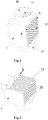
Figure 3 is a schematic drawing of a mechanism for flushing lint of the invention inEmbodiment 2; -
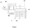
Figure 4 is a schematic drawing of the heat exchanger ofEmbodiment 2 of the invention; -
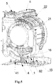
Figure 5 is a schematic drawing of integral washing-drying machine ofEmbodiment 3 of the invention; -
Figure 6 is a schematic drawing of air channels of heat exchanger ofEmbodiment 3 of the invention; -
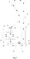
Figure 7 is a schematic drawing of circular drying system of clothes dryer ofEmbodiment 3 of the invention; -
Figure 8 is a schematic drawing of air channels of heat exchanger and residual heat recovery device ofEmbodiment 4 of the invention; -
Figure 9 is a structural schematic drawing of the heat exchanger and residual heat recovery device ofEmbodiment 4 of the invention; -
Figure 10 is a schematic drawing of circular drying system of clothes dryer ofEmbodiment 5 of the invention. - As shown in
Figure 1 and Figure 2 , the heat exchanger for condensation in clothes drying is installed in a clothes dryer or washing machine having the function of drying. Theheat exchanger 1, made of plastic film, is an external air-cooled heat exchanger. The interior of the heat exchanger comprises two groups of air channels going towards different directions and not communicating with each other, which are respectively a condensingair channel 11 and anexternal air channel 12. Each group of air channel is composed of a plurality of air chambers. The air chambers of two groups of air channels are arranged alternately in turn. The space between neighboring air chambers of the same group of air channel is an air chamber of the other group of air channel, and all of them are made of interval plastic film walls. - A condensate fan 15 (see
Figures 5 and6 ) is set on one end of theexternal air channel 12, and the other end directly leads to the outside. The hot and humid air is put in through one end of the condensingair channel 11, and the condensed air and water are exhausted through the other end. The condensingair channel 11 is composed ofair chambers 13. Theexternal air channel 12 is composed ofair chambers 14. The space between neighboringair chambers 13 of the condensingair channel 11 is anair chamber 14 of theexternal air channel 12. To prevent condensate water forming thermal resistance through sticking to the wall of air chamber and reducing the condensing efficiency, the hot and humid air in the condensingair channel 11 flow from top to bottom. Preferably, external air inside theexternal air channel 12 flow transversely.
wherein, the thickness L of the plastic film is in the range of 0.05mm to 1.5mm; preferably, the thickness of the plastic film is in the rang of 0.08mm to 0.8mm; more preferably, the thickness of the plastic film is in the rang of 0.1mm to 0.5mm. The embodiment adopts the plastic film with the thickness of 0.1mm. The shape of the cross-section of the air chamber is not limited to rectangular, circle or elliptic type. Various corrugated shape for the drop of condensate water can also be set on the wall of the air chamber, or combination of the aforesaid shapes. - The plastic film of the present invention has heat resistance, for example, polyimide film, which is undistorted even at a temperature of 150°C. The plastic film in the embodiment is polyethylene film with a distortion temperature of 80-100°C.
- As shown in
Figures 3 and4 , on the basis ofEmbodiment 1, a mechanism for flushing lint is comprised. The mechanism for flushing lint is arranged at one end of a hot andhumid air inlet 16 of the condensingair channel 11 of theheat exchanger 1. The mechanism for flushing lint included a flushingvalve connection 82 communicated with the exterior, a flushingpassageway 83 communicating to the flushing valve connection and being set annularly along the air inlet for the hot and humid air of the heat exchanger, and a flushingmouth 81 set along the edge of the flushing passageway for flushing water towards the air channel for the hot and humid air in the inside of the heat exchanger. - As shown in
Figure 5-7 , the foregoing heat exchanger may be installed inside a integral washing-drying machine (seeFigure 5 ) or a clothes dryer (seeFigure 7 ), which comprises aclothes tub 2, anair outlet 21, afilter 3, aheat exchanger 1, awater collection box 4, a dryingfan 5, aheating unit 6 and anair inlet 22. Theair outlet 21 communicates with theheat exchanger 1 which communicates with thewater collection box 4; and thewater collection box 4 communicates with theair inlet 22. Thefilter 3 is arranged between theair outlet 22 and theheat exchanger 1, and the dryingfan 5 and theheating unit 6 are arranged between thewater collection box 4 andair inlet 22 in turn. Thewater collection box 4 communicates with the outside through a drainingpump 41, and a water levelinductive switch 42 for controlling to turn on the drainingpump 41 is installed in thewater collection box 4. Specifically, thewater collection box 4 comprises a water-holdingbox 43 and a top cover 44 (seeFigures 3 and4 ). Aninlet 45 communicating with a hot andhumid air outlet 17 of the condensing air channel of the heat exchanger and anoutlet 46 communicating with theair inlet 22 of the clothes dryer are arranged on thetop cover 44. - Wherein, the
clothes tub 2, theair outlet 21, thefilter 3, the dryingfan 5, theheat unit 6 and theair inlet 22 all may adopt the designs in prior arts. The air inlet and the air outlet are both the air inlet and the air outlet of the clothes tub. Theheating unit 6 is generally made of heating pipe or heater strip or heating plate. Thefilter 3 is composed of at least one layer of filter net, which is dismountable. - As shown in
Figure 7 , in drying, the hot and humid air from the air outlet of theclothes tub 2 enters the condensingair channel 11 of theheat exchange 1 along the pipeline. In the heat exchanger, the external air passed in through theexternal air channel 12 of theheat exchanger 1 exchanges heat with the hot and humid air in the condensingair channel 11. Temperature of the hot and humid air in condensingair channel 11 drops while its relative humidity rises. Partial air around the wall of the air chambers gets saturated, and vapors in the air precipitate and flow into thewater collection box 4 along with the wall of the air chambers. When the water level is monitored to reach the pre-set position by the water levelinductive switch 42, the drainingpump 41 is turned on, discharging the condensate water. The condensed low-heat and low-humidity air passes through thewater collection box 4, and is sent to theheating unit 6 for heating by the dryingfan 5, and then reflows into theclothes tub 2 through the air inlet. - As shown in
Figures 8 and 9 , the drying system of this embodiment consists of theheat exchanger 1 ofEmbodiment heat recovery device 7. The interior of the residualheat recovery device 7 comprises two groups of air channels, namely, a hot andhumid air channel 71 and a residual heatrecovery air channel 72. The two groups of air channels form a heat exchange structure. The hot andhumid air channel 71 communicates with the condensingair channel 11, thewater collection box 4 and the residual heatrecovery air channel 72 in turn through ventilating ducts. - Specifically, the residual
heat recovery device 7 comprises a shell 70, and aheat exchanger 73 arranged inside the shell. The hot andhumid air channel 71 and the residual heatrecovery air channel 72 are arranged in theheat exchanger 73 in the way of bidirectional cross convection. Corresponding to two groups of air channels, anair inlet 74 of the hot and humid air channel and anair outlet 75 of the residual heat recovery air channel are arranged on the upper of the shell 70, and anair outlet 76 of the hot and humid air channel and anair inlet 77 of the residual heat recovery air channel are arranged on the lower of the shell 70. With respect to theair inlet 77 and theair outlet 75 of the residual heatrecovery air channel 77, theair inlet 74 and theoutlet 76 of the hot air and humid air channel all are arranged on the cross. Theair outlet 76 of the hot and humid air channel of the residualheat recovery device 7 communicates with theair inlet 16 of the hot and humid air channel of the condensingair channel 11 of theheat exchanger 1, and theair inlet 77 of the residual heat recovery air channel communicates with theoutlet 46 of thewater collection box 4. - In the interior of the
heat exchanger 73, two groups of heat exchange fins form the hot and humid air channel and the residual heat recovery air channel. Each group of the heat exchange fins form a plurality of air channels along the same direction. The space between the neighboring air channels of the same group is an air channel of the other group. The air channels composed of two groups of heat exchange fins are set by interval, which forms the heat exchange structure with bidirectional cross convection. - Alternatively, as shown in
Figure 9 , the interior of theheat exchanger 73 is composed of multiple parallel plates.Air channels air channels heat exchanger 73 can also adopt the existing plate-interval recuperative heat exchanger. - As shown in
Figure 10 , the difference from that ofEmbodiment 3 is that the clothes dryer or the washing-drying machine of the embodiment is arranged the residualheat recovery device 7 on the basis ofEmbodiment 4. The residualheat recovery device 7 is set between thefilter 3 and theheat exchanger 1, also between thewater collection box 4 and the dryingfan 5. The hot andhumid air channel 71 communicates with thefilter 3 and theheat exchanger 1, and the residual heatrecovery air channel 72 communicates with thewater collection box 4 and the dryingfan 5. The hot and humid air passes out from the air outlet of theclothes tub 2, and flows through the hot andhumid air channel 71 of the residualheat recovery device 7, theheat exchanger 1 and thewater collection box 4 successively, then flows through the residual heatrecovery air channel 72 of the residualheat recovery device 7. Thus, it is completed to recover the residual heat. - As shown in
Figure 10 , in drying, the hot and humid air from the air outlet of theclothes tub 2 goes in the hot andhumid air channel 71 through the air inlet of the hot andhumid air channel 74 of the residual heat recovery device, and is discharged from theair outlet 76 of the hot andhumid air channel 76, and then enters the condensingair channel 11 of theheat exchanger 1. In the heat exchanger, the external air passed in through theexternal air channel 12 of theheat exchanger 1 exchanges heat with the hot and humid air in the condensingair channel 11. Temperature of the hot and humid air in condensingair channel 11 drops, while its relative humidity rises. Partial air around the wall of the air chambers gets saturated, and vapors in the air precipitate and flow into thewater collection box 4 along with the wall of the air chambers.. When the water level is monitored to reach the pre-set position by the water levelinductive switch 42, the drainingpump 41 is turned on, discharging the condensate water. The condensed low-heat and low-humidity air passes through thewater collection box 4, and is sent to theair inlet 77 of the residual heat recovery air channel of the residual heat recovery device, and then goes in the residual heatrecovery air channel 72. The temperature of the condensed air water decreases while water content decreases. So, The low temperature air getting back to the residual heat recovery device exchanges heat with the hot and humid air inside the hot andhumid air channel 71 again. As a result, before going into theheat exchanger 1, the hot and humid air is cool in advance. The dry air through the residualheat recovery device 7 heats up before being heated inside theheating unit 6, thus it becomes preheated. Therefore, energy consumption on reheating the air in the drying recycle system is reduced, and the noise generated by condensing air in high flow rate is reduced. - Based on the above embodiments, to prevent lint blocking the
heat exchanger 1 or the residualheat recovery device 7 and to better filter the lint, thefilter 3 comprises at least two layers of filter net. And the layer next to the outlet is dismountable and convenient for flushing. - In this invention, the heat exchanger made of plastic film is adopted to air-cool the external air, which is efficient and easy to be processed, meanwhile, it is easier to be assembled and installed in accordance with the drying power of the clothes dryer or integral washing-drying machine. Besides, clothes dryer or integral washing-drying machine arranged with such heat exchanger is lighter, more convenient and cost-saving in transportation.
Claims (13)
- A heat exchanger (1) for condensation in clothes drying, the heat exchanger being an external air-cooled type heat exchanger comprising two groups of air channels with different directions and not communicating with each other, said groups of air channels defining a condensing air channel (11) and an external air channel (12), respectively,
wherein each group of air channels is composed of a plurality of air chambers (13, 14), the air chambers (13, 14) of the two groups of air channels being arranged alternately in turn and the space between each two neighboring air chambers (13, 14) of the same group of air channels is an air chamber (14, 13) of the other group of air channels,
wherein one end of the condensing air channel (11) is a hot and humid air inlet (16) and the other end is a hot and humid air outlet (17) for condensed air,
wherein a condensate fan (15) is set at one end of the external air channel (12) and the other end of the external air channel (12) is communicated to the outside, and
wherein a mechanism for flushing lint is provided,
characterized in that
the mechanism for flushing lint is arranged at one end of the hot and humid air inlet (16) of the condensing air channel (11) of the heat exchanger and comprises:a flushing valve connection (82) communicating with the outside,a flushing passageway (83) communicating with the flushing valve connection (82) and being set annularly along the hot and humid air inlet (16), anda flushing mouth (81) set along the inside edge of the flushing passageway (83) for flushing water towards the air chambers (13) of the condensing air channel (11). - The heat exchanger for condensation in clothes drying according to Claim 1, wherein the heat exchanger is composed of plastic film with a thickness of 0.05mm to 1.5mm, and two neighboring air chambers (13, 14) are spaced by the plastic film wall.
- The heat exchanger for condensation in clothes drying according to Claim 2, wherein the thickness of the plastic film is in the range of 0.08mm to 0.8mm.
- The heat exchanger for condensation in clothes drying according to Claim 1, wherein each air chamber (13, 14) of the heat exchanger has a ventilation clearance of 1mm to 20mm.
- A clothes dryer or integral washing-drying machine comprising a heat exchanger (1) according to any of Claims 1 to 4, a clothes tub (2) with an air outlet (21) and an air inlet (22), a filter (3), a water collection box (4), a drying fan (5), and a heating unit (6), wherein:the air outlet (21) is communicated with the heat exchanger (1),the heat exchanger (1) is communicated with the water collection box (4),the water collection box (4) is communicated with the air inlet (22),the filter (3) is arranged between the air outlet (21) and the heat exchanger (1), andthe drying fan (5) and the heating unit (6) are arranged between the water collection box (4) and the air inlet (22) in turn.
- The clothes dryer or integral washing-drying machine according to Claim 5, wherein:the water collection box (4) is communicated with the outside via a draining pump (41), anda water level inductive switch (42) for controlling to turn on and off the draining pump (41) is installed in the water collection box (4).
- The clothes dryer or integral washing-drying machine according to Claim 5 or 6, wherein the filter (3) is composed of at least one layer of filter net, and at least one layer of filter net is dismountable.
- A clothes drying system comprising a heat exchanger (1) according to any of Claims 1 to 4, a water collection box (4) and a residual heat recovery device (7), wherein:two groups of air channels defining a hot and humid air channel (71) and a residual heat recovery air channel (72), respectively, are arranged in the residual heat recovery device (7) and form a heat exchange structure, andthe hot and humid air channel (71) is communicated via the condensing air channel (11) of the heat exchanger (1) and the water collection box (4) with the residual heat recovery air channel (72) through ventilating ducts.
- The clothes drying system according to Claim 8, wherein:the water collection box (4) comprises a box body and a top cover (44),the top cover (44) is respectively provided with an inlet (45) communicating with the condensing air channel (11) of the heat exchanger (1) and an outlet (46) communicating with the residual heat recovery air channel (72) of the residual heat recovery device (7),a draining pump (41) is installed in the water collection box (4),a water level inductive switch (42) for controlling to turn on and off the draining pump (41) is installed in the water collection box (4).
- The clothes drying system according to Claim 8 or 9, wherein:the residual heat recovery device (7) comprises a shell (70) and a heat exchanger (73) arranged inside the shell,the hot and humid air channel (71) and the residual heat recovery air channel (72) are arranged in the heat exchanger (73) of the residual heat recovery device (7) in the way of bidirectional cross convection, andcorresponding to the two groups of air channels of the residual heat recovery device (7) an inlet (74) of the hot and humid air channel (71) and an outlet (75) of the residual heat recovery air channel (72) are respectively arranged at an upper side of the shell (70), and an outlet (76) of the hot and humid air channel (71) and an inlet (77) of the residual heat recovery air channel (72) are arranged at a lower side of the shell (70).
- The clothes drying system according to Claim 10, wherein:the heat exchanger (73) is composed of two groups of heat exchange fins,each group of heat exchange fins form a plurality of air channels along the same direction,the space between the neighboring air channels of the same group is an air channel of the other group,the air channels composed of two groups of heat exchange fins are set by interval, which forms the heat exchange structure with bidirectional cross convection.
- A clothes dryer integral washing-drying machine comprising a clothes drying system according to any of Claims 8 to 11, a clothes tub (2) with an air inlet (22) and an air outlet (21), and a heating unit (6), wherein:the air outlet (21) is communicated with the hot and humid air channel (71) of the residual heat recovery device (7),the air inlet (22) is communicated with the residual heat recovery air channel (72) of the residual heat recovery device (7), andthe heating unit (6) is arranged between the residual heat recovery air channel (72) of the residual heat recovery device (7) and the air inlet (22).
- The clothes dryer according to Claim 12, wherein:a filter (3) is set between the air outlet (21) and the hot and humid air channel (71) of the residual heat recovery device (7),the filter (3) is composed of at least one layer of filter net, anda drying fan (5) is set between the residual heat recovery air channel (72) of the residual heat recovery device (7) and the air inlet (22).
Applications Claiming Priority (4)
| Application Number | Priority Date | Filing Date | Title |
|---|---|---|---|
| CN201110349942.7A CN102517857B (en) | 2011-11-08 | 2011-11-08 | A kind of drying condensation heat-exchange system with function of recovering waste heat and dryer |
| CN201110350840.7A CN102505437B (en) | 2011-11-08 | 2011-11-08 | A kind of drying condensation heat exchanger and dryer |
| CN201110427039.8A CN102517860B (en) | 2011-12-19 | 2011-12-19 | Drying system and the thread waste clearing method for same of drying system |
| PCT/CN2012/080441 WO2013067837A1 (en) | 2011-11-08 | 2012-08-22 | Heat exchanger for condensation in clothes drying and clothes drying system and clothes dryer and drying method thereof |
Publications (3)
| Publication Number | Publication Date |
|---|---|
| EP2778281A1 EP2778281A1 (en) | 2014-09-17 |
| EP2778281A4 EP2778281A4 (en) | 2015-07-08 |
| EP2778281B1 true EP2778281B1 (en) | 2021-04-07 |
Family
ID=48288507
Family Applications (1)
| Application Number | Title | Priority Date | Filing Date |
|---|---|---|---|
| EP12847897.1A Active EP2778281B1 (en) | 2011-11-08 | 2012-08-22 | Heat exchanger for condensation in clothes drying and clothes drying system and clothes dryer |
Country Status (4)
| Country | Link |
|---|---|
| US (1) | US9869052B2 (en) |
| EP (1) | EP2778281B1 (en) |
| JP (1) | JP6069797B2 (en) |
| WO (1) | WO2013067837A1 (en) |
Families Citing this family (17)
| Publication number | Priority date | Publication date | Assignee | Title |
|---|---|---|---|---|
| KR102057859B1 (en) * | 2013-01-25 | 2019-12-20 | 엘지전자 주식회사 | Laundry Machine |
| WO2015009034A1 (en) * | 2013-07-16 | 2015-01-22 | Lg Electronics Inc. | Clothes dryer |
| CN104911878B (en) * | 2014-03-14 | 2018-12-25 | 青岛海尔滚筒洗衣机有限公司 | A kind of superposing type heat exchanger |
| CN104674499A (en) * | 2015-02-28 | 2015-06-03 | 珠海格力电器股份有限公司 | Washing and drying integrated machine |
| CN106192322A (en) * | 2015-04-29 | 2016-12-07 | 青岛海尔洗衣机有限公司 | A kind of condensing laundry dryer and condensing drying method |
| CN205223685U (en) * | 2015-12-30 | 2016-05-11 | Tcl家用电器(合肥)有限公司 | Wash and dry by fire all -in -one |
| CN106049008A (en) * | 2016-07-28 | 2016-10-26 | 广东格兰仕集团有限公司 | Cabinet type clothes dryer and clothes drying method thereof |
| KR102378474B1 (en) * | 2017-08-09 | 2022-03-25 | 엘지전자 주식회사 | Laundry Treating Apparatus |
| CN107462064A (en) * | 2017-09-15 | 2017-12-12 | 广东纽恩泰新能源科技发展有限公司 | A kind of heat pump dryer for heating and dehumidifying integration |
| CN112626816A (en) * | 2019-10-08 | 2021-04-09 | 青岛海尔滚筒洗衣机有限公司 | Clothes dryer condenser and clothes dryer |
| US11851807B2 (en) | 2019-11-07 | 2023-12-26 | Whirlpool Corporation | Method of removing heat from a clothes tumbling system on the outside of the cabinet |
| EP4238474B1 (en) | 2021-04-22 | 2025-06-25 | Samsung Electronics Co., Ltd. | Shoe management apparatus and controlling method thereof |
| CN117265847A (en) * | 2022-06-14 | 2023-12-22 | 无锡小天鹅电器有限公司 | Dehumidifying apparatus and laundry treating apparatus thereof |
| USD1006360S1 (en) | 2022-11-29 | 2023-11-28 | WALTON.K.K International Business Group, Inc. | Lint catching device |
| USD1007794S1 (en) | 2022-11-29 | 2023-12-12 | WALTON.K.K International Business Group, Inc. | Lint catching device |
| CN115948888B (en) * | 2022-12-29 | 2026-01-23 | 珠海格力电器股份有限公司 | Washing and drying equipment and drying control method thereof |
| CN117322663B (en) * | 2023-11-09 | 2025-08-05 | 中国农业科学院烟草研究所(中国烟草总公司青州烟草研究所) | A baking device with intelligent temperature and humidity regulation |
Family Cites Families (25)
| Publication number | Priority date | Publication date | Assignee | Title |
|---|---|---|---|---|
| JPS55110200U (en) | 1979-01-26 | 1980-08-02 | ||
| JPS58195595A (en) | 1982-05-08 | 1983-11-14 | 株式会社日立製作所 | clothes dryer |
| DE3404569A1 (en) * | 1984-02-09 | 1985-08-14 | Peter Dipl.-Ing. Kinast | Device for automated cleaning of the thermally conductive surfaces of heating systems |
| DE3738031C2 (en) | 1987-11-09 | 1995-10-12 | Bosch Siemens Hausgeraete | Method and device for removing lint from a condensate separator designed as a heat exchanger |
| JPH0425683U (en) * | 1990-06-22 | 1992-02-28 | ||
| JP2657130B2 (en) | 1991-06-28 | 1997-09-24 | 三洋電機株式会社 | Clothes dryer |
| DE4212965A1 (en) * | 1992-04-18 | 1993-10-21 | Bauknecht Hausgeraete | Condensn. dryer with self-cleaning - has condensn. water container including filter element located above water level in process air current, has low cooling water consumption |
| DE4306215A1 (en) * | 1993-02-27 | 1994-09-01 | Licentia Gmbh | Program-controlled laundry drier with a heat-pump circuit |
| EP0982427B1 (en) | 1998-08-25 | 2003-03-05 | Joma-Polytec Kunststofftechnik GmbH | Cross flow heat exchanger for laundry drier with condenser |
| US6648067B1 (en) * | 1999-11-17 | 2003-11-18 | Joma-Polytec Kunststofftechnik Gmbh | Heat exchanger for condensation laundry dryer |
| GB0108549D0 (en) | 2001-04-05 | 2001-05-23 | D B K Technitherm Ltd | Improvements relating to drier devices |
| CN2532098Y (en) * | 2002-03-31 | 2003-01-22 | 牛献中 | Drying device capable of recovering heat energy for dry washing machine and water-washing drying-machine |
| KR100459143B1 (en) | 2002-11-27 | 2004-12-03 | 엘지전자 주식회사 | flow route for deflation cooling fan in condenser for condesing type clothes drier |
| RU2006114770A (en) * | 2003-09-29 | 2007-11-10 | Селф Пропеллед Рисерч энд Дивелопмент Спешелистс,эЛэЛСи (US) | DRYING DEVICE (OPTIONS), WASHING DEVICE AND DRYING CHAMBER (OPTIONS) |
| KR101235193B1 (en) | 2005-06-13 | 2013-02-20 | 삼성전자주식회사 | Washing machine and control method thereof |
| JP4676291B2 (en) | 2005-09-22 | 2011-04-27 | パナソニック株式会社 | Clothes dryer |
| DE102006061211A1 (en) * | 2006-12-22 | 2008-06-26 | BSH Bosch und Siemens Hausgeräte GmbH | Method for removing lint from a heat exchanger of a domestic appliance, and corresponding domestic appliance |
| US7458171B1 (en) * | 2007-01-29 | 2008-12-02 | Lentz Luke E | Dehumidifier clothes dryer apparatus |
| EP2203585B1 (en) * | 2007-09-04 | 2017-08-16 | LG Electronics Inc. | Dehumidifying apparatus for dryer |
| DE102007049060A1 (en) * | 2007-10-12 | 2009-04-16 | BSH Bosch und Siemens Hausgeräte GmbH | Method for operating a rinsing liquid device in a domestic appliance for the care of items of laundry and rinsing liquid device |
| DE102008006347A1 (en) | 2008-01-28 | 2009-07-30 | BSH Bosch und Siemens Hausgeräte GmbH | Condensation dryer and method for its operation |
| CN101684610B (en) * | 2008-09-26 | 2011-11-09 | 博西华电器(江苏)有限公司 | Clothes drying device |
| CN102505437B (en) | 2011-11-08 | 2016-11-23 | 青岛海尔滚筒洗衣机有限公司 | A kind of drying condensation heat exchanger and dryer |
| CN102517857B (en) | 2011-11-08 | 2016-08-31 | 青岛海尔滚筒洗衣机有限公司 | A kind of drying condensation heat-exchange system with function of recovering waste heat and dryer |
| CN102517860B (en) | 2011-12-19 | 2016-08-31 | 青岛海尔滚筒洗衣机有限公司 | Drying system and the thread waste clearing method for same of drying system |
-
2012
- 2012-08-22 US US14/355,607 patent/US9869052B2/en active Active
- 2012-08-22 EP EP12847897.1A patent/EP2778281B1/en active Active
- 2012-08-22 WO PCT/CN2012/080441 patent/WO2013067837A1/en not_active Ceased
- 2012-08-22 JP JP2014540296A patent/JP6069797B2/en not_active Expired - Fee Related
Non-Patent Citations (1)
| Title |
|---|
| None * |
Also Published As
| Publication number | Publication date |
|---|---|
| EP2778281A1 (en) | 2014-09-17 |
| JP6069797B2 (en) | 2017-02-01 |
| US20140298674A1 (en) | 2014-10-09 |
| WO2013067837A1 (en) | 2013-05-16 |
| US9869052B2 (en) | 2018-01-16 |
| EP2778281A4 (en) | 2015-07-08 |
| JP2014534035A (en) | 2014-12-18 |
Similar Documents
| Publication | Publication Date | Title |
|---|---|---|
| US9869052B2 (en) | Heat exchanger for condensation in clothes drying and clothes drying system and clothes dryer and drying method thereof | |
| CN102505437B (en) | A kind of drying condensation heat exchanger and dryer | |
| CN102517861B (en) | Clothes drying temperature detection control method and dryer | |
| US8590172B2 (en) | Dehumidifying apparatus for dryer | |
| CN102517857A (en) | Heat-exchange system with waste heat recovery function for dry clothes condensation and cloths dryer | |
| EP2702199B1 (en) | Heat pump laundry dryer | |
| CN106884297B (en) | A kind of drying equipment and drying method | |
| CN109237910A (en) | A kind of energy-saving enclosed heat pump sludge drying dehumidification system and technique | |
| CN104605804A (en) | Dish-washing machine and drying system of same | |
| CN104233737A (en) | Water condenser, washing-drying machine and clothes drying method | |
| CN102505439B (en) | A kind of clothes-drying method and dryer | |
| CN102011295B (en) | Drying machine | |
| EP2452009B1 (en) | Clothes drying apparatus | |
| CN201648804U (en) | Heat exchanger for air condensing type clothes drying machine | |
| CN101564200B (en) | Tobacco redrying energy-saving technique and energy-saving device of redrying machine thereof | |
| KR20060007470A (en) | Drum washing machine | |
| CN208566926U (en) | A kind of semiconductor refrigerating dehumidizer | |
| KR20130024715A (en) | Seaweed dryer for saving energy | |
| CN202989623U (en) | Condensed water circulating type energy-saving dryer | |
| KR20090011183U (en) | Dehumidifying food dryer | |
| CN201598493U (en) | Condensing heat exchanger used for clothes dryer | |
| CN212504547U (en) | A water source heat pump sludge drying device | |
| CN219531597U (en) | Exhaust device for roller dryer | |
| CN105157369B (en) | Integral type waste heat recovery drying unit | |
| CN223909958U (en) | A fabric drying device |
Legal Events
| Date | Code | Title | Description |
|---|---|---|---|
| PUAI | Public reference made under article 153(3) epc to a published international application that has entered the european phase |
Free format text: ORIGINAL CODE: 0009012 |
|
| 17P | Request for examination filed |
Effective date: 20140602 |
|
| AK | Designated contracting states |
Kind code of ref document: A1 Designated state(s): AL AT BE BG CH CY CZ DE DK EE ES FI FR GB GR HR HU IE IS IT LI LT LU LV MC MK MT NL NO PL PT RO RS SE SI SK SM TR |
|
| DAX | Request for extension of the european patent (deleted) | ||
| RA4 | Supplementary search report drawn up and despatched (corrected) |
Effective date: 20150608 |
|
| RIC1 | Information provided on ipc code assigned before grant |
Ipc: D06F 58/24 20060101AFI20150601BHEP Ipc: D06F 58/20 20060101ALI20150601BHEP Ipc: D06F 58/22 20060101ALI20150601BHEP |
|
| GRAP | Despatch of communication of intention to grant a patent |
Free format text: ORIGINAL CODE: EPIDOSNIGR1 |
|
| STAA | Information on the status of an ep patent application or granted ep patent |
Free format text: STATUS: GRANT OF PATENT IS INTENDED |
|
| INTG | Intention to grant announced |
Effective date: 20201127 |
|
| RAP1 | Party data changed (applicant data changed or rights of an application transferred) |
Owner name: HAIER GROUP CORPORATION Owner name: QINGDAO HAIER DRUM WASHING MACHINE CO., LTD. |
|
| GRAS | Grant fee paid |
Free format text: ORIGINAL CODE: EPIDOSNIGR3 |
|
| GRAA | (expected) grant |
Free format text: ORIGINAL CODE: 0009210 |
|
| STAA | Information on the status of an ep patent application or granted ep patent |
Free format text: STATUS: THE PATENT HAS BEEN GRANTED |
|
| AK | Designated contracting states |
Kind code of ref document: B1 Designated state(s): AL AT BE BG CH CY CZ DE DK EE ES FI FR GB GR HR HU IE IS IT LI LT LU LV MC MK MT NL NO PL PT RO RS SE SI SK SM TR |
|
| REG | Reference to a national code |
Ref country code: GB Ref legal event code: FG4D |
|
| REG | Reference to a national code |
Ref country code: AT Ref legal event code: REF Ref document number: 1379827 Country of ref document: AT Kind code of ref document: T Effective date: 20210415 Ref country code: CH Ref legal event code: EP |
|
| REG | Reference to a national code |
Ref country code: DE Ref legal event code: R096 Ref document number: 602012075152 Country of ref document: DE |
|
| REG | Reference to a national code |
Ref country code: IE Ref legal event code: FG4D |
|
| REG | Reference to a national code |
Ref country code: LT Ref legal event code: MG9D |
|
| REG | Reference to a national code |
Ref country code: NL Ref legal event code: MP Effective date: 20210407 Ref country code: AT Ref legal event code: MK05 Ref document number: 1379827 Country of ref document: AT Kind code of ref document: T Effective date: 20210407 |
|
| PG25 | Lapsed in a contracting state [announced via postgrant information from national office to epo] |
Ref country code: HR Free format text: LAPSE BECAUSE OF FAILURE TO SUBMIT A TRANSLATION OF THE DESCRIPTION OR TO PAY THE FEE WITHIN THE PRESCRIBED TIME-LIMIT Effective date: 20210407 Ref country code: AT Free format text: LAPSE BECAUSE OF FAILURE TO SUBMIT A TRANSLATION OF THE DESCRIPTION OR TO PAY THE FEE WITHIN THE PRESCRIBED TIME-LIMIT Effective date: 20210407 Ref country code: BG Free format text: LAPSE BECAUSE OF FAILURE TO SUBMIT A TRANSLATION OF THE DESCRIPTION OR TO PAY THE FEE WITHIN THE PRESCRIBED TIME-LIMIT Effective date: 20210707 Ref country code: LT Free format text: LAPSE BECAUSE OF FAILURE TO SUBMIT A TRANSLATION OF THE DESCRIPTION OR TO PAY THE FEE WITHIN THE PRESCRIBED TIME-LIMIT Effective date: 20210407 Ref country code: NL Free format text: LAPSE BECAUSE OF FAILURE TO SUBMIT A TRANSLATION OF THE DESCRIPTION OR TO PAY THE FEE WITHIN THE PRESCRIBED TIME-LIMIT Effective date: 20210407 Ref country code: FI Free format text: LAPSE BECAUSE OF FAILURE TO SUBMIT A TRANSLATION OF THE DESCRIPTION OR TO PAY THE FEE WITHIN THE PRESCRIBED TIME-LIMIT Effective date: 20210407 |
|
| PG25 | Lapsed in a contracting state [announced via postgrant information from national office to epo] |
Ref country code: NO Free format text: LAPSE BECAUSE OF FAILURE TO SUBMIT A TRANSLATION OF THE DESCRIPTION OR TO PAY THE FEE WITHIN THE PRESCRIBED TIME-LIMIT Effective date: 20210707 Ref country code: PT Free format text: LAPSE BECAUSE OF FAILURE TO SUBMIT A TRANSLATION OF THE DESCRIPTION OR TO PAY THE FEE WITHIN THE PRESCRIBED TIME-LIMIT Effective date: 20210809 Ref country code: PL Free format text: LAPSE BECAUSE OF FAILURE TO SUBMIT A TRANSLATION OF THE DESCRIPTION OR TO PAY THE FEE WITHIN THE PRESCRIBED TIME-LIMIT Effective date: 20210407 Ref country code: ES Free format text: LAPSE BECAUSE OF FAILURE TO SUBMIT A TRANSLATION OF THE DESCRIPTION OR TO PAY THE FEE WITHIN THE PRESCRIBED TIME-LIMIT Effective date: 20210407 Ref country code: IS Free format text: LAPSE BECAUSE OF FAILURE TO SUBMIT A TRANSLATION OF THE DESCRIPTION OR TO PAY THE FEE WITHIN THE PRESCRIBED TIME-LIMIT Effective date: 20210807 Ref country code: LV Free format text: LAPSE BECAUSE OF FAILURE TO SUBMIT A TRANSLATION OF THE DESCRIPTION OR TO PAY THE FEE WITHIN THE PRESCRIBED TIME-LIMIT Effective date: 20210407 Ref country code: GR Free format text: LAPSE BECAUSE OF FAILURE TO SUBMIT A TRANSLATION OF THE DESCRIPTION OR TO PAY THE FEE WITHIN THE PRESCRIBED TIME-LIMIT Effective date: 20210708 Ref country code: SE Free format text: LAPSE BECAUSE OF FAILURE TO SUBMIT A TRANSLATION OF THE DESCRIPTION OR TO PAY THE FEE WITHIN THE PRESCRIBED TIME-LIMIT Effective date: 20210407 Ref country code: RS Free format text: LAPSE BECAUSE OF FAILURE TO SUBMIT A TRANSLATION OF THE DESCRIPTION OR TO PAY THE FEE WITHIN THE PRESCRIBED TIME-LIMIT Effective date: 20210407 |
|
| REG | Reference to a national code |
Ref country code: DE Ref legal event code: R097 Ref document number: 602012075152 Country of ref document: DE |
|
| PG25 | Lapsed in a contracting state [announced via postgrant information from national office to epo] |
Ref country code: RO Free format text: LAPSE BECAUSE OF FAILURE TO SUBMIT A TRANSLATION OF THE DESCRIPTION OR TO PAY THE FEE WITHIN THE PRESCRIBED TIME-LIMIT Effective date: 20210407 Ref country code: EE Free format text: LAPSE BECAUSE OF FAILURE TO SUBMIT A TRANSLATION OF THE DESCRIPTION OR TO PAY THE FEE WITHIN THE PRESCRIBED TIME-LIMIT Effective date: 20210407 Ref country code: DK Free format text: LAPSE BECAUSE OF FAILURE TO SUBMIT A TRANSLATION OF THE DESCRIPTION OR TO PAY THE FEE WITHIN THE PRESCRIBED TIME-LIMIT Effective date: 20210407 Ref country code: CZ Free format text: LAPSE BECAUSE OF FAILURE TO SUBMIT A TRANSLATION OF THE DESCRIPTION OR TO PAY THE FEE WITHIN THE PRESCRIBED TIME-LIMIT Effective date: 20210407 Ref country code: SM Free format text: LAPSE BECAUSE OF FAILURE TO SUBMIT A TRANSLATION OF THE DESCRIPTION OR TO PAY THE FEE WITHIN THE PRESCRIBED TIME-LIMIT Effective date: 20210407 Ref country code: SK Free format text: LAPSE BECAUSE OF FAILURE TO SUBMIT A TRANSLATION OF THE DESCRIPTION OR TO PAY THE FEE WITHIN THE PRESCRIBED TIME-LIMIT Effective date: 20210407 |
|
| PLBE | No opposition filed within time limit |
Free format text: ORIGINAL CODE: 0009261 |
|
| STAA | Information on the status of an ep patent application or granted ep patent |
Free format text: STATUS: NO OPPOSITION FILED WITHIN TIME LIMIT |
|
| 26N | No opposition filed |
Effective date: 20220110 |
|
| REG | Reference to a national code |
Ref country code: CH Ref legal event code: PL |
|
| PG25 | Lapsed in a contracting state [announced via postgrant information from national office to epo] |
Ref country code: MC Free format text: LAPSE BECAUSE OF FAILURE TO SUBMIT A TRANSLATION OF THE DESCRIPTION OR TO PAY THE FEE WITHIN THE PRESCRIBED TIME-LIMIT Effective date: 20210407 |
|
| REG | Reference to a national code |
Ref country code: BE Ref legal event code: MM Effective date: 20210831 |
|
| PG25 | Lapsed in a contracting state [announced via postgrant information from national office to epo] |
Ref country code: LI Free format text: LAPSE BECAUSE OF NON-PAYMENT OF DUE FEES Effective date: 20210831 Ref country code: CH Free format text: LAPSE BECAUSE OF NON-PAYMENT OF DUE FEES Effective date: 20210831 |
|
| PG25 | Lapsed in a contracting state [announced via postgrant information from national office to epo] |
Ref country code: IS Free format text: LAPSE BECAUSE OF FAILURE TO SUBMIT A TRANSLATION OF THE DESCRIPTION OR TO PAY THE FEE WITHIN THE PRESCRIBED TIME-LIMIT Effective date: 20210807 Ref country code: LU Free format text: LAPSE BECAUSE OF NON-PAYMENT OF DUE FEES Effective date: 20210822 Ref country code: AL Free format text: LAPSE BECAUSE OF FAILURE TO SUBMIT A TRANSLATION OF THE DESCRIPTION OR TO PAY THE FEE WITHIN THE PRESCRIBED TIME-LIMIT Effective date: 20210407 |
|
| PG25 | Lapsed in a contracting state [announced via postgrant information from national office to epo] |
Ref country code: IE Free format text: LAPSE BECAUSE OF NON-PAYMENT OF DUE FEES Effective date: 20210822 Ref country code: BE Free format text: LAPSE BECAUSE OF NON-PAYMENT OF DUE FEES Effective date: 20210831 |
|
| PGFP | Annual fee paid to national office [announced via postgrant information from national office to epo] |
Ref country code: IT Payment date: 20220831 Year of fee payment: 11 Ref country code: GB Payment date: 20220824 Year of fee payment: 11 Ref country code: DE Payment date: 20220831 Year of fee payment: 11 |
|
| PGFP | Annual fee paid to national office [announced via postgrant information from national office to epo] |
Ref country code: FR Payment date: 20220822 Year of fee payment: 11 |
|
| PG25 | Lapsed in a contracting state [announced via postgrant information from national office to epo] |
Ref country code: HU Free format text: LAPSE BECAUSE OF FAILURE TO SUBMIT A TRANSLATION OF THE DESCRIPTION OR TO PAY THE FEE WITHIN THE PRESCRIBED TIME-LIMIT; INVALID AB INITIO Effective date: 20120822 Ref country code: CY Free format text: LAPSE BECAUSE OF FAILURE TO SUBMIT A TRANSLATION OF THE DESCRIPTION OR TO PAY THE FEE WITHIN THE PRESCRIBED TIME-LIMIT Effective date: 20210407 |
|
| REG | Reference to a national code |
Ref country code: DE Ref legal event code: R119 Ref document number: 602012075152 Country of ref document: DE |
|
| GBPC | Gb: european patent ceased through non-payment of renewal fee |
Effective date: 20230822 |
|
| PG25 | Lapsed in a contracting state [announced via postgrant information from national office to epo] |
Ref country code: MK Free format text: LAPSE BECAUSE OF FAILURE TO SUBMIT A TRANSLATION OF THE DESCRIPTION OR TO PAY THE FEE WITHIN THE PRESCRIBED TIME-LIMIT Effective date: 20210407 |
|
| PG25 | Lapsed in a contracting state [announced via postgrant information from national office to epo] |
Ref country code: GB Free format text: LAPSE BECAUSE OF NON-PAYMENT OF DUE FEES Effective date: 20230822 |
|
| PG25 | Lapsed in a contracting state [announced via postgrant information from national office to epo] |
Ref country code: IT Free format text: LAPSE BECAUSE OF NON-PAYMENT OF DUE FEES Effective date: 20230822 Ref country code: GB Free format text: LAPSE BECAUSE OF NON-PAYMENT OF DUE FEES Effective date: 20230822 Ref country code: FR Free format text: LAPSE BECAUSE OF NON-PAYMENT OF DUE FEES Effective date: 20230831 Ref country code: DE Free format text: LAPSE BECAUSE OF NON-PAYMENT OF DUE FEES Effective date: 20240301 |
|
| PG25 | Lapsed in a contracting state [announced via postgrant information from national office to epo] |
Ref country code: MT Free format text: LAPSE BECAUSE OF FAILURE TO SUBMIT A TRANSLATION OF THE DESCRIPTION OR TO PAY THE FEE WITHIN THE PRESCRIBED TIME-LIMIT Effective date: 20210407 |
|
| PG25 | Lapsed in a contracting state [announced via postgrant information from national office to epo] |
Ref country code: TR Free format text: LAPSE BECAUSE OF FAILURE TO SUBMIT A TRANSLATION OF THE DESCRIPTION OR TO PAY THE FEE WITHIN THE PRESCRIBED TIME-LIMIT Effective date: 20210407 |