EP2777769A1 - Radiation treatment system and control method therefor - Google Patents
Radiation treatment system and control method therefor Download PDFInfo
- Publication number
- EP2777769A1 EP2777769A1 EP14171617.5A EP14171617A EP2777769A1 EP 2777769 A1 EP2777769 A1 EP 2777769A1 EP 14171617 A EP14171617 A EP 14171617A EP 2777769 A1 EP2777769 A1 EP 2777769A1
- Authority
- EP
- European Patent Office
- Prior art keywords
- image data
- imaging
- data
- radiotherapy system
- radiotherapy
- Prior art date
- Legal status (The legal status is an assumption and is not a legal conclusion. Google has not performed a legal analysis and makes no representation as to the accuracy of the status listed.)
- Granted
Links
- 238000000034 method Methods 0.000 title claims description 14
- 230000005855 radiation Effects 0.000 title description 20
- 238000001959 radiotherapy Methods 0.000 claims abstract description 153
- 238000003384 imaging method Methods 0.000 claims abstract description 76
- 210000000920 organ at risk Anatomy 0.000 description 48
- 230000015654 memory Effects 0.000 description 46
- 238000010586 diagram Methods 0.000 description 34
- 230000006870 function Effects 0.000 description 25
- 238000012545 processing Methods 0.000 description 12
- 230000004044 response Effects 0.000 description 8
- 230000007246 mechanism Effects 0.000 description 6
- 230000005856 abnormality Effects 0.000 description 5
- 102100035353 Cyclin-dependent kinase 2-associated protein 1 Human genes 0.000 description 4
- 230000005540 biological transmission Effects 0.000 description 4
- 206010028980 Neoplasm Diseases 0.000 description 3
- 102100029860 Suppressor of tumorigenicity 20 protein Human genes 0.000 description 3
- 238000012986 modification Methods 0.000 description 3
- 230000004048 modification Effects 0.000 description 3
- 102100036848 C-C motif chemokine 20 Human genes 0.000 description 2
- 239000002131 composite material Substances 0.000 description 2
- 238000012937 correction Methods 0.000 description 2
- 238000009826 distribution Methods 0.000 description 2
- 238000010894 electron beam technology Methods 0.000 description 2
- 238000002595 magnetic resonance imaging Methods 0.000 description 2
- 239000002184 metal Substances 0.000 description 2
- 230000008054 signal transmission Effects 0.000 description 2
- 210000001835 viscera Anatomy 0.000 description 2
- 230000003936 working memory Effects 0.000 description 2
- 230000005461 Bremsstrahlung Effects 0.000 description 1
- 230000003187 abdominal effect Effects 0.000 description 1
- 210000000988 bone and bone Anatomy 0.000 description 1
- 201000011510 cancer Diseases 0.000 description 1
- 238000010835 comparative analysis Methods 0.000 description 1
- 238000013461 design Methods 0.000 description 1
- 210000000232 gallbladder Anatomy 0.000 description 1
- 230000001678 irradiating effect Effects 0.000 description 1
- 239000004973 liquid crystal related substance Substances 0.000 description 1
- 210000004185 liver Anatomy 0.000 description 1
- 210000004072 lung Anatomy 0.000 description 1
- 239000011159 matrix material Substances 0.000 description 1
- 210000000056 organ Anatomy 0.000 description 1
- 239000002245 particle Substances 0.000 description 1
- 238000007781 pre-processing Methods 0.000 description 1
- 210000000664 rectum Anatomy 0.000 description 1
- 230000000241 respiratory effect Effects 0.000 description 1
- 239000004065 semiconductor Substances 0.000 description 1
- 230000035945 sensitivity Effects 0.000 description 1
- 239000000126 substance Substances 0.000 description 1
- 230000009466 transformation Effects 0.000 description 1
Images


Classifications
-
- A—HUMAN NECESSITIES
- A61—MEDICAL OR VETERINARY SCIENCE; HYGIENE
- A61N—ELECTROTHERAPY; MAGNETOTHERAPY; RADIATION THERAPY; ULTRASOUND THERAPY
- A61N5/00—Radiation therapy
- A61N5/10—X-ray therapy; Gamma-ray therapy; Particle-irradiation therapy
- A61N5/103—Treatment planning systems
-
- A—HUMAN NECESSITIES
- A61—MEDICAL OR VETERINARY SCIENCE; HYGIENE
- A61B—DIAGNOSIS; SURGERY; IDENTIFICATION
- A61B6/00—Apparatus for radiation diagnosis, e.g. combined with radiation therapy equipment
- A61B6/54—Control of apparatus or devices for radiation diagnosis
- A61B6/542—Control of apparatus or devices for radiation diagnosis involving control of exposure
-
- A—HUMAN NECESSITIES
- A61—MEDICAL OR VETERINARY SCIENCE; HYGIENE
- A61B—DIAGNOSIS; SURGERY; IDENTIFICATION
- A61B6/00—Apparatus for radiation diagnosis, e.g. combined with radiation therapy equipment
- A61B6/48—Diagnostic techniques
- A61B6/488—Diagnostic techniques involving pre-scan acquisition
-
- A—HUMAN NECESSITIES
- A61—MEDICAL OR VETERINARY SCIENCE; HYGIENE
- A61N—ELECTROTHERAPY; MAGNETOTHERAPY; RADIATION THERAPY; ULTRASOUND THERAPY
- A61N5/00—Radiation therapy
- A61N5/10—X-ray therapy; Gamma-ray therapy; Particle-irradiation therapy
- A61N2005/1085—X-ray therapy; Gamma-ray therapy; Particle-irradiation therapy characterised by the type of particles applied to the patient
- A61N2005/1091—Kilovoltage or orthovoltage range photons
-
- A—HUMAN NECESSITIES
- A61—MEDICAL OR VETERINARY SCIENCE; HYGIENE
- A61N—ELECTROTHERAPY; MAGNETOTHERAPY; RADIATION THERAPY; ULTRASOUND THERAPY
- A61N5/00—Radiation therapy
- A61N5/10—X-ray therapy; Gamma-ray therapy; Particle-irradiation therapy
- A61N5/1048—Monitoring, verifying, controlling systems and methods
Definitions
- Embodiments according to the present invention relate to a radiotherapy system and a control method for the radiotherapy system that can carry out radiotherapy.
- image data is generated by imaging during treatment planning, and treatment plan data is generated based on the image data.
- image data is generated by imaging just before the treatment.
- the image data obtained just before the treatment is aligned with the image data for the treatment plan to compute a difference of the image data obtained just before the treatment from the image data for the treatment plan, and then repositioning is carried out by shifting the patient by the difference from the imaging position just before the treatment. After the repositioning, radiotherapy is carried out by irradiating a treatment site of the patient.
- Examples of conventional arts relating to the embodiments include Japanese Patent Application Publication (Laid-Open: KOKAI) No. 2010-69086 .
- both images are aligned with each other based on shading (CT values, image density, values of luminance, or the like) of overall data of both the images including sites unrelated to treatment
- shading CT values, image density, values of luminance, or the like
- shift of internal organs in the data of both the images tends not to be taken into account and an area of interest such as a treatment site may not be aligned with high accuracy.
- chest and abdominal organs such as a lung, a liver, and the like are irradiated
- a normal site other than a treatment site might be irradiated.
- Radiotherapy systems and control methods for the radiotherapy systems of the embodiments will be described with reference to the accompanying drawings.
- the radiotherapy system includes: a placing unit configured to place a subject; an imaging unit configured to perform an imaging of the subject; a region setting unit configured to set a required region of first image data obtained by the imaging unit performing the imaging of the subject and to set a corresponding required region of second image data obtained by, before the imaging, performing a pre-imaging of the subject; a histogram generating unit configured to generate a dose-volume histogram of the required region of the first image data and to generate a dose-volume histogram of the required region of the second image data; a difference computing unit configured to compute a difference between the dose-volume histogram of the required region of the first image data and the dose-volume histogram of the required region of the second image data; and an outputting unit configured to, if it is determined that the difference is greater than a threshold value, output the determination to an outside.
- the present first embodiment provides the control method for the radiotherapy system includes: performing an imaging of a subject; setting a required region of first image data obtained by the imaging unit performing the imaging of the subject and setting a corresponding required region of second image data obtained by, before the imaging, performing a pre-imaging of the subject; generating a dose-volume histogram of the required region of the first image data and generating a dose-volume histogram of the required region of the second image data; computing a difference between the dose-volume histogram of the required region of the first image data and the dose-volume histogram of the required region of the second image data; and outputting the determination to an outside if it is determined that the difference is greater than a threshold value.
- the radiotherapy system includes: a placing unit configured to place a subject; an imaging unit configured to perform an imaging of the subject; an image storage unit configured to store therein first image data obtained by performing a pre-imaging of the subject in radiotherapy planning; a region storage unit configured to store therein position information of a required region included in the first image data; and an image aligning unit configured to use the position information of the required region to align the first image data with second image data obtained by the imaging unit performing the imaging of the subject before radiotherapy.
- the present second embodiment provides the control method for the radiotherapy system includes: setting position information of a required region included in the first image data obtained by performing a pre-imaging of the subject in radiotherapy planning; and aligning the first image data with second image data obtained by the imaging unit performing the imaging of the subject before radiotherapy, using the position information.
- Fig. 1 is an external view showing a part of a radiotherapy system of a first embodiment.
- Fig. 2 is a block diagram showing the entirety of the radiotherapy system of the first embodiment.
- Figs. 1 and 2 show the radiotherapy system 1 of the first embodiment.
- the radiotherapy system 1 includes a console 10, an imaging system 20, a bed system 30, a treatment planning system 40, and a radiotherapy system (linac: a radiotherapy system that carries out treatment by irradiation based on treatment plan data) 50.
- a radiotherapy system (linac: a radiotherapy system that carries out treatment by irradiation based on treatment plan data) 50.
- the imaging system 20, the bed system 30, and the radiotherapy system 50 are usually installed in an examination room.
- the console 10 is usually installed in a control room adjacent to the examination room.
- the treatment planning system 40 is installed outside the examination room and the control room.
- the treatment planning system 40 may be installed in the control room or may be an integrated apparatus with the console 10.
- representative examples of the imaging system 20 include an X-ray CT system, an MRI (magnetic resonance imaging) apparatus, and an X-ray apparatus. The following describes the case in which an X-ray CT system 20a is used as the imaging system 20.
- the console 10 of the radiotherapy system 1 has a computer-based configuration and is able to communicate with a trunk network of a hospital such as a LAN (local area network), not shown.
- the console 10 is broadly composed of basic hardware such as a CPU (central processing unit) 11, main memory 12, image memory 13, an HDD (hard disc drive) 14, an input device 15, and a display device 16.
- the CPU 11 and each hardware component of the console 10 are connected with each other via buses as common signal transmission paths.
- the console 10 may include a recording medium drive.
- the CPU 11 is a control device having a configuration of an integrated circuit (LSI) in which an electronic circuit composed of a semiconductor is housed in a package with multiple terminals. If an instruction is input by an operator such as a physician operating the input device 15, the CPU 11 executes a program stored in the main memory 12. Alternatively, the CPU 11 loads a program stored in the HDD 14, a program transferred from the network and installed in the HDD 14, or a program read out from a recording medium mounted in a recording medium drive (not shown) and installed in the HDD 14, into the main memory 12 to execute the program.
- LSI integrated circuit
- the main memory 12 is a storage device that includes ROM (read only memory), RAM (random access memory), or the like.
- the main memory 12 is used for storage of IPL (initial program loading), a BIOS (basic input/output system), and data. Also, the main memory 12 is used as working memory for the CPU 11 and to temporarily store data.
- the image memory 13 is a storage device in which slice data as two-dimensional image data and treatment plan volume data and pretreatment volume data as three-dimensional image data are stored.
- the HDD 14 is a storage device containing undetachable metal disks on which a magnetic substance is applied or evaporated.
- the HDD 14 is a storage device in which programs installed in the console 10 (in addition to application programs, including an OS (operating system)) and data are stored.
- the OS may be allowed to provide a GUI (graphical user interface) that makes heavy use of graphics in information displayed on the display device 16 so that an operator such as an operational person can perform basic operations through the input device 15.
- GUI graphical user interface
- the input device 15 is a pointing device that can be operated by the operator and input signals according to operations are sent to the CPU 11.
- the display device 16 includes an image combining circuit, VRAM (video random access memory), and a display that are not shown.
- the image combining circuit generates composite data into which character data of a variety of parameters is combined with image data.
- the VRAM expands the composite data into display image data to be displayed on the display.
- the display is composed of a liquid crystal display, a CRT (cathode ray tube), or the like, and sequentially displays items of the display image data as display images.
- the console 10 controls operations of an X-ray CT system 20a, a bed system 30, and a radiotherapy system 50.
- the console 10 also performs correction processing (preprocessing) such as logarithmic transformation processing and sensitivity correction on raw data input from a DAS 24 of the X-ray CT system 20a to generate projection data, and generates slice data as two-dimensional image data and volume data as three-dimensional image data on the basis of the projection data.
- correction processing preprocessing
- the X-ray CT system 20a of the radiotherapy system 1 images the region including the treatment site.
- the X-ray CT system 20a includes an X-ray tube 21 as a radiation source, an aperture 22, an X-ray detector 23, the DAS (data acquisition system) 24, a rotation portion 25, a high voltage supplying device 26, an aperture driving device 27, a rotation driving device 28, and an imaging controller 29.
- the X-ray tube 21 causes an electron beam to collide with a metal target according to tube voltage supplied from the high voltage supplying device 26 to generate bremsstrahlung X-rays, and applies the X-rays to the X-ray detector 23.
- the X-rays applied from the X-ray tube 21 form fan beam X-rays and cone beam X-rays.
- the aperture 22 adjusts an area being irradiated with the X-rays by the X-ray tube 21. That is, the X-ray irradiated area can be modified by the aperture driving device 27 adjusting an opening of the aperture 22.
- the X-ray detector 23 is a matrix form X-ray detector, that is, the X-ray detector 23 is a two-dimensional array type X-ray detector (also referred to as a multi-slice type sensor) having a plurality of channels in a channel direction and a plurality of rows of X-ray detecting elements in a slice direction.
- the X-ray detecting elements of the X-ray detector 23 detect the X-rays applied from the X-ray tube 21.
- the DAS 24 amplifies a signal of transmission data detected by each X-ray detecting element of the X-ray detector 23 to convert the signal into a digital signal. Output data of the DAS 24 is supplied to the console 10 through the imaging controller 29.
- the rotation portion 25 holds the X-ray tube 21, the aperture 22, the X-ray detector 23, and the DAS 24 as a single unit.
- the rotation portion 25 can rotate about the patient O with the X-ray tube 21, the aperture 22, the X-ray detector 23, and the DAS 24 as a single unit and with the X-ray tube 21 and the X-ray detector 23 opposing each other. It is assumed that a direction parallel to an axis of rotation of the rotation portion 25 is defined as a z axis direction, and a plane orthogonal to the z axis direction is defined as an x axis direction and a y axis direction.
- the high voltage supplying device 26 supplies the X-ray tube 21 with power required for X-ray irradiation in response to control of the imaging controller 29.
- the aperture driving device 27 has a mechanism that uses the aperture 22 to adjust an area irradiated with X-rays in the slice direction in response to control of the imaging controller 29.
- the rotation driving device 28 has a mechanism that, in response to control of the imaging controller 29, rotates the rotation portion 25 about a cavity portion (not shown) with a position relationship of the rotation portion 25 maintained.
- the imaging controller 29 comprises a CPU and a memory.
- the imaging controller 29 controls the X-ray tube 21, the X-ray detector 23, the DAS 24, the high voltage supplying device 26, the aperture driving device 27, and the rotation driving device 28 to perform a scan with the operations of the bed system 30.
- the bed system 30 of the radiotherapy system 1 includes a table-top driving device 32, a table-top 33, and a bed controller 39.
- the patient O can be placed on the table-top 33.
- the table-top driving device 32 has a mechanism that moves the table-top 33 up and down along the y axis direction and moves the table-top 33 backward and forward along the z axis direction in response to control of the bed controller 39.
- the table-top driving device 32 also has a mechanism that rotates the table-top 33 about the y axis direction in response to control of the bed controller 39.
- the bed controller 39 comprises a CPU and a memory.
- the bed controller 39 controls the table-top driving device 32 to perform a scan with the operations of the X-ray CT system 20a.
- the bed controller 39 also controls the table-top driving device 32 to perform radiotherapy with the operations of the radiotherapy system 50.
- the treatment planning system 40 of the radiotherapy system 1 generates treatment plan data for radiotherapy to be carried out by the radiotherapy system 50 on the basis of the slice data and the volume data generated by the console 10 after imaged by the X-ray CT system 20a. Under the control of the console 10 based on the treatment plan data generated by the treatment planning system 40, a site to be treated of the patient O is irradiated by the radiotherapy system 50.
- the treatment planning system 40 has a computer-based configuration and can communicate with the trunk network of the hospital such as a LAN, not shown.
- the treatment planning system 40 is broadly composed of basic hardware such as a CPU 41, main memory 42, treatment plan memory 43, an HDD 44, an input device 45, and a display device 46.
- the CPU 41 and each hardware component of the treatment planning system 40 are connected with each other via buses as common signal transmission paths.
- the treatment planning system 40 may include a recording medium drive.
- a configuration of the CPU 41 is equivalent to that of the CPU 11 of the console 10. If the operator operates the input device 45 to input an instruction, the CPU 41 executes a program stored in the main memory 42. Alternatively, the CPU 41 loads a program stored in the HDD 44, a program transferred from the network and installed in the HDD 44, or a program read out from a recording medium mounted in a recording medium drive (not shown) and installed in the HDD 44, into the main memory 42 to execute the program.
- a configuration of the main memory 42 is equivalent to that of the main memory 12 of the console 10.
- the main memory 42 is used for storage of IPL, a BIOS, and data. Also, the main memory 42 is used as working memory for the CPU 41 and to temporarily store data.
- the treatment plan memory 43 is a storage device in which treatment plan data is stored.
- a configuration of the HDD 44 is equivalent to that of the HDD 14 of the console 10.
- a configuration of the input device 45 is equivalent to that of the input device 15 of the console 10.
- a configuration of the display device 46 is equivalent to that of the display device 16 of the console 10.
- the treatment planning system 40 determines a position of the treatment site of the patient O and a shape of the treatment site based on the image data generated by the X-ray CT system 20a, and also determines a type of radiation (an X-ray, an electron beam, a neutron beam, a proton beam, a heavy particle beam, or the like) to be applied to the treatment site, energy of the radiation, and a radiation field.
- a type of radiation an X-ray, an electron beam, a neutron beam, a proton beam, a heavy particle beam, or the like
- the radiotherapy system 50 of the radiotherapy system 1 can generally generate radiation in the MV range.
- the radiotherapy system 50 is provided with the aperture (collimator) at a radiation generation port, and the aperture provides an irradiation shape and a dose distribution that are based on the treatment plan.
- multileaf collimators MLCs that can form dose distributions corresponding to complex shapes of tumors by a plurality of movable leaves have been often used as the apertures.
- the radiotherapy system 50 adjusts an irradiation amount with a radiation field formed by the aperture and eliminates or reduces a treatment site of the patient O.
- a combination of the X-ray CT system 20a, the bed system 30, and the radiotherapy system 50 is called a "linac-CT.”
- the radiotherapy system 50 includes a radiation source 51 as a radiation source, an aperture 52, an arm portion 55, a high voltage supplying device 56, an aperture driving device 57, a rotation driving device 58, and a treatment controller 59.
- the radiation source 51 generates radiation according to tube voltage supplied from the high voltage supplying device 56.
- the aperture 52 adjusts an area being irradiated by the radiation source 51. That is, the irradiated area can be modified by the aperture driving device 57 adjusting an opening of the aperture 52.
- the arm portion 55 holds the radiation source 51 and the aperture 52 as a single unit.
- the arm portion 55 can rotate about the patient O with the radiation source 51 and the aperture 52 as a single unit.
- the high voltage supplying device 56 supplies the radiation source 51 with power required for irradiation in response to control of the treatment controller 59.
- the aperture driving device 57 has a mechanism that uses the aperture 52 to adjust an irradiated area in response to control of the treatment controller 59.
- the rotation driving device 58 has a mechanism that rotates the arm portion 55 about a connection portion (not shown) between the arm portion 55 and a supporting portion (not shown) in response to control of the treatment controller 59.
- the treatment controller 59 comprises a CPU and a memory.
- the treatment controller 59 controls, in accordance with the treatment plan data generated by the treatment planning system 40, the radiation source 51, the high voltage supplying device 56, and the aperture driving device 57 to perform irradiation for treatment with the operations of the bed system 30.
- Fig. 3 is a block diagram showing functions of the radiotherapy system 1 of the first embodiment.
- the CPU 11 of the console 10 and the CPU 41 of the treatment planning system 40 execute programs, and thereby as shown in Fig. 3 , the radiotherapy system 1 functions as an imaging performing unit 61, an image data generating unit 62, a treatment plan data generating unit 63, an interface unit 64, a contour setting unit 65, an interface unit 66, a DVH (dose-volume histogram) computing unit 67, a dose difference computing unit 68, a threshold value determining unit 69, a reporting control unit 70, and a treatment performing unit 71. All or a part of the components 61 to 71 of the radiotherapy system 1 may be included in the radiotherapy system 1 as hardware.
- the imaging performing unit 61 of the console 10 has a function of controlling the operations of the imaging controller 29 of the X-ray CT system 20a and the bed controller 39 of the bed system 30 to, for a treatment plan, image a region including a treatment site of the patient O. Also, the imaging performing unit 61 has a function of controlling the operations of the imaging controller 29 of the X-ray CT system 20a and the bed controller 39 of the bed system 30 to image the region including the treatment site of the patient O after the treatment planning, for example, just before the treatment.
- the image data generating unit 62 of the console 10 has a function of generating slice data as two-dimensional image data by the imaging performing unit 61 performing processing such as image reconstructing processing on the transmission data obtained by the X-ray CT system 20a. Also, the image data generating unit 62 has a function of generating volume data as three-dimensional image data based on the slice data corresponding to a plurality of slices. Specifically, the image data generating unit 62 generates the slice data by imaging it for a treatment plan and generates the volume data (treatment plan volume data) VP for the treatment plan for the treatment planning system 40.
- the image data generating unit 62 generates slice data by imaging it just before the treatment by the radiotherapy system 50 and generates volume data (pretreatment volume data) VQ obtained just before the treatment.
- Each of the volume data VP and the volume data VQ generated by the image data generating unit 62 is stored in a storage device such as the image memory 13.
- Fig. 4 is a diagram schematically showing an example of a display image based on the treatment plan volume data VP.
- Fig. 5 is a diagram schematically showing an example of a display image based on the pretreatment volume data VQ.
- Fig. 4 shows a display image based on the treatment plan volume data VP.
- Fig. 5 shows a display image based on the pretreatment volume data VQ. If the display image shown in Fig. 4 is compared with the display image shown in Fig. 5 , it can be seen that there is a difference between the volume data VP and the volume data VQ in structure images corresponding to the structure of the patient O.
- the treatment plan data generating unit 63 of the treatment planning system 40 shown in Fig. 3 has a function of setting a treatment plan by setting irradiation conditions such as a direction and number of irradiation, and a radiation intensity with a contour of a body of the patient O and a region of an affected part taken into consideration based on the treatment plan volume data VP stored in the image memory 13, to generate treatment plan data.
- the treatment plan data generating unit 63 sets, on the basis of the treatment plan volume data VP, a required area, for example, a contour SP of an OAR (organ at risk) not to be irradiated.
- the treatment plan data generating unit 63 sets the contour SP of the OAR through the interface unit 64.
- the contour SP of the OAR set by the treatment plan data generating unit 63 is three-dimensional position information.
- the treatment plan data generating unit 63 may set a contour SP1 of only one OAR or may set contours SP1 SP2, ... of a plurality of OARs.
- the treatment plan data generating unit 63 may set a comparison point (isocenter).
- Fig. 6 is a diagram schematically showing an example of a display image of a contour SP of an OAR based on the treatment plan volume data VP.
- the treatment plan data generating unit 63 computes a DV histogram HP of the OAR based on the set contour SP of the OAR.
- the DV histogram computed by the treatment plan data generating unit 63 is a graph of relationship between dose and volume in a required region and is used for comparative evaluation of a plurality of items of treatment plan data.
- Fig. 7 is a diagram showing general DV histograms of OARs (a rectum and a gallbladder) as required regions.
- Fig. 8 is a diagram showing an example of a DV histogram HP of the contour SP of the OAR as the required region shown in Fig. 6 .
- the treatment plan data generating unit 63 generates the treatment plan data based on the treatment plan volume data VP generated by the X-ray CT system 20a included in the radiotherapy system 1, but the treatment plan data generating unit 63 is not limited thereto.
- the treatment plan data generating unit 63 may generate the treatment plan data based on treatment plan volume data generated by an imaging system external to the radiotherapy system 1.
- the treatment plan data generated by the treatment plan data generating unit 63 is stored in a storage device such as the treatment plan memory 43.
- the interface unit 64 of the treatment planning system 40 is an interface such as a GUI that displays on the display device 46 a display image that is based on the treatment plan volume data VP and enables, on the display image, the operator to select the contour SP of the OAR through the input device 45 operated by the operator.
- the contour setting unit 65 of the console 10 has a function of setting, on the basis of the pretreatment volume data VQ stored in the image memory 13, a contour SQ of the OAR corresponding to the contour SP of the OAR stored in the treatment plan memory 43.
- the contour setting unit 65 sets the contour SQ of the OAR through the interface unit 66.
- the contour setting unit 65 aligns the volume data VP with the volume data VQ to set the contour SQ of the OAR corresponding to the contour SP of the OAR stored in the treatment plan memory 43.
- An aligning method may be a method for aligning the entire volume data VP with the entire volume data VQ so as to decrease a difference in CT values (image density, values of luminance, and the like) between the volume data VP and the volume data VQ, or may be a method for aligning the entire volume data VP with the entire volume data VQ using "non-rigid bodies" linked with modification and shift of the volume data VP and the volume data VQ.
- the contour setting unit 65 sets only a contour SQ of one OAR (SQ1) if only a contour SP of one OAR (SP1) is set, and sets contours SQ of a plurality of OARs (SQ1, SQ2, ...) if contours SP of a plurality of OARs (SP1, SP2, 7) are set.
- Fig. 9 is a drawing schematically showing an example of a display image of a contour SQ of an OAR based on the pretreatment volume data VQ.
- the interface unit 66 of the console 10 is an interface such as a GUI that displays on the display device 16 a display image that is based on the pretreatment volume data VQ stored in the image memory 13 and enables, on the display image, the operator to select the contour SQ through the input device 15 operated by the operator.
- the DVH computing unit 67 of the console 10 has a function of computing a DV histogram HQ of the OAR based on the contour SQ of the OAR set by the contour setting unit 65.
- the DV histogram HQ of the OAR computed by the DVH computing unit 67 is displayed on the display device 16 through the interface unit 66.
- Fig. 10 is a diagram showing an example of the DV histogram HQ of the contour SQ of the OAR shown in Fig. 9 .
- the dose difference computing unit 68 of the console 10 has a function of computing a difference D between doses in the same volume on the basis of the DV histogram HP stored in the treatment plan memory 43 and the DV histogram HQ computed by the DVH computing unit 67. That is, the dose difference computing unit 68 computes a difference D between the DV histograms HP and HQ in each volume.
- Fig. 11 is a diagram showing the DV histogram HP shown in Fig. 8 , the DV histogram HQ shown in Fig. 10 , and the difference D in each volume.
- the threshold value determining unit 69 of the console 10 has a function of determining whether or not the difference D in each volume computed by the dose difference computing unit 68 is equal to or smaller than a threshold value. For example, the threshold value determining unit 69 determines whether or not a maximum difference Dmax (shown in Fig. 11 ) of the difference D in each of the volumes is equal to or smaller than a threshold value. If the maximum difference Dmax is greater than the threshold value, a position of the patient O seen when the treatment plan volume data VP is generated (during the imaging) is significantly different from a position of the patient O seen when the pretreatment volume data VQ is generated (during the imaging). Therefore, if the radiotherapy system 50 subsequently carries out irradiation, a position different from the position determined in the treatment planning is actually irradiated.
- a maximum difference Dmax shown in Fig. 11
- the reporting control unit 70 has a function of, if the threshold value determining unit 69 determines that the maximum difference Dmax is greater than the threshold value, reporting (output) an abnormality to the operator. For example, the reporting control unit 70 reports an abnormality to the operator through the display device 16.
- the treatment performing unit 71 of the console 10 has a function of, if the threshold value determining unit 69 determines that a difference D is equal to or smaller than the threshold value, controlling the operations of the treatment controller 59 of the radiotherapy system 50 and the operations of the bed controller 39 of the bed system 30 to treat a treatment site of the patient O.
- contour SP of the required region set by the treatment plan data generating unit 63 and the contour setting unit 65 is not limited to a contour SP of an OAR.
- the contour SP of the required region set by the treatment plan data generating unit 63 and the contour setting unit 65 may be a contour SP of a PTV (planning target volume) as a treatment site.
- Fig. 12 is a diagram showing a general DV histogram of a PTV as a required region.
- the radiotherapy system 1 controls the operations of the bed controller 39 of the bed system 30 to insert the table-top 33 into an opening of the X-ray CT system 20a. Then, as shown in Fig. 13 , the radiotherapy system 1 controls the operations of the imaging controller 29 of the X-ray CT system 20a to image a region including the treatment site of the patient O for treatment planning (step ST1).
- the radiotherapy system 1 performs processing such as image reconstructing processing on transmission data obtained by the X-ray CT system 20a in step ST1 to generate slice data as two-dimensional image data, and generates treatment plan volume data VP as three-dimensional image data based on the slice data corresponding to a plurality of slices (step ST2).
- the treatment plan volume data VP generated in step ST2 is stored in a storage device such as the image memory 13 (step ST3).
- the radiotherapy system 1 sets a treatment plan by setting irradiation conditions such as a direction and number of irradiation, and a radiation intensity with a contour of a body of the patient O and a region of an affected part taken into consideration based on the treatment plan volume data VP stored in the image memory 13 in step ST3, to generate treatment plan data (step ST4).
- the radiotherapy system 1 sets a contour SP of an OAR as a required region based on the treatment plan volume data VP (step ST4a).
- the radiotherapy system 1 also computes a DV histogram HP of the contour SP of the OAR set in step ST4a (step ST4b).
- the treatment plan data generated in step ST4 is stored in a storage device such as the treatment plan memory 43 (step ST5).
- the radiotherapy system 1 controls the operations of the bed controller 39 of the bed system 30 to retreat the table-top 33 from the opening of the X-ray CT system 20a. Then, the patient O is removed from the table-top 33 of the bed system 30 of the radiotherapy system 1.
- the radiotherapy system 1 controls the operations of the bed controller 39 of the bed system 30 to insert the table-top 33 into the opening of the X-ray CT system 20a. Then, as shown in Fig. 14 , the radiotherapy system 1 controls the operations of the imaging controller 29 of the X-ray CT system 20a to image the region including the treatment site of the patient O just before the treatment (step ST11).
- the radiotherapy system 1 performs processing such as image reconstructing processing on transmission data obtained by the X-ray CT system 20a in step ST11 to generate slice data as two-dimensional image data, and generates pretreatment volume data VQ as three-dimensional image data based on the slice data corresponding to a plurality of slices (step ST12).
- the pretreatment volume data VQ generated in step ST12 is stored in a storage device such as the image memory 13 (step ST13).
- the radiotherapy system 1 sets a contour SQ of the OAR corresponding to the contour SP of the OAR stored in the treatment plan memory 43 based on the pretreatment volume data VQ stored in the image memory 13 in step ST13 (step ST14).
- the radiotherapy system 1 also computes a DV histogram HQ of the contour SQ of the OAR based on the treatment plan set in step ST4 and the contour SQ of the OAR set in step ST14 (step ST15).
- the radiotherapy system 1 computes differences D between doses in the same volumes based on the DV histogram HP of the contour SP of the OAR set in step ST4b in Fig. 13 and the DV histogram HQ of the contour SQ of the OAR set in step ST15 (step ST16).
- the radiotherapy system 1 determines whether or not a maximum difference Dmax of the difference D in each of the volumes computed in step ST16 is equal to or smaller than a threshold value (step ST17). If yes in step ST17, that is, if it is determined that the maximum difference Dmax of the difference D in each of the volumes is equal to or smaller than the threshold value, the radiotherapy system 1 allows for processing in a next step, the step ST19 (step ST18).
- the radiotherapy system 1 controls the operations of the treatment controller 59 of the radiotherapy system 50 to treat the treatment site of the patient O (step ST19).
- the radiotherapy system 1 controls the operations of the bed controller 39 of the bed system 30 to retreat the table-top 33 from the radiotherapy system 50.
- the patient O is removed from the table-top 33 of the bed system 30 of the radiotherapy system 1.
- step ST17 if no in step ST17, that is, if it is determined that the maximum difference Dmax of the difference D in each of the volumes is greater than the threshold value, the radiotherapy system 1 reports an abnormality to the operator (step ST20).
- step ST20 the radiotherapy system 1 reports an abnormality to the operator through the display device 16.
- step ST21 the radiotherapy system 1 performs the pretreatment imaging (step ST11).
- the treatment planning system 40 reconsiders the treatment plan set in step ST4 and sets a treatment plan again (step ST31). For example, in step ST31, with the treatment plan set in step ST4 as an initial setting, the irradiation conditions such as a direction and number of irradiation, and radiation intensity are set again. Then, the radiotherapy system 1 computes a DV histogram HQ of the contour SQ of the OAR based on the treatment plan set again in step ST31 and the contour SQ of the OAR set in step ST14 (step ST15), and the processing proceeds to a step ST16.
- the radiotherapy system 1 may also compute the DV histogram HQ of the contour SQ of the OAR associated with the irradiation conditions simultaneously as the irradiation conditions are set again in step ST31 to immediately display the DV histogram HQ.
- it is suitable to display the DV histogram HP computed in step ST4b with the DV histogram HQ, which is immediately displayed. The operator can judge suitability by comparing the immediately displayed DV histogram HQ with the DV histogram HP to allow for the processing in step ST19 without stopping by the step ST17.
- the DV histogram HP of the contour SP of the OAR or the like included in the treatment plan volume data VP is compared with the DV histogram HQ of the contour SQ of the OAR or the like included in the pretreatment volume data VQ, and if a difference therebetween is significant, the fact that a setting of the patient O is required again to carry out treatment based on a treatment plan can be reported to the operator.
- proper treatment based on a treatment plan can be assisted.
- proper treatment can be assisted by setting a treatment plan again.
- An external view of a radiotherapy system 1A of a second embodiment is similar to the external view of the radiotherapy system 1 of the first embodiment shown in Fig. 1 and an entire configuration of the radiotherapy system 1A of the second embodiment is similar to the entire configuration of the radiotherapy system 1 of the first embodiment shown in Fig. 2 , so that descriptions thereof are omitted.
- Fig. 17 is a block diagram showing functions of the radiotherapy system 1A of the second embodiment.
- the CPU 11 of the console 10 and the CPU 41 of the treatment planning system 40 execute programs, and thereby as shown in Fig. 17 , the radiotherapy system 1A functions as the imaging performing unit 61, the image data generating unit 62, a treatment plan data generating unit 83, an interface unit 84, a contour setting unit 85, an interface unit 86, a comparison point (reference point) setting unit 87, a specific contour setting unit 88, a aligning unit 89, a difference computing unit 90, and a treatment performing unit 91. All or a part of the components 61, 62 and 83 to 91 of the radiotherapy system 1A may be included in the radiotherapy system 1A as hardware.
- the treatment plan data generating unit 83 of the treatment planning system 40 has a function of generating treatment plan data based on the treatment plan volume data VP stored in the image memory 13.
- the treatment plan data generating unit 83 sets, on the basis of the treatment plan volume data VP, a contour SP for a structure region corresponding to structure in the patient O and sets a comparison point (isocenter) RP.
- the structure in the patient O includes a PTV as a treatment site, an OAR not to be irradiated, other internal organs, bones, and the like.
- the treatment plan data generating unit 83 sets the contour SP and the comparison point RP through the interface unit 84.
- the contour SP and the comparison point RP set by the treatment plan data generating unit 83 are three-dimensional position information.
- the treatment plan data generating unit 83 may set only one contour SP1 or may set a plurality of contours SP1, SP2...
- the treatment plan data generating unit 83 generates the treatment plan data based on the treatment plan volume data VP generated by the X-ray CT system 20a included in the radiotherapy system 1A, but the treatment plan data generating unit 83 is not limited thereto.
- the treatment plan data generating unit 83 may generate the treatment plan data based on treatment plan volume data generated by an imaging system external to the radiotherapy system 1A.
- the treatment plan data generated by the treatment plan data generating unit 83 is stored in a storage device such as the treatment plan memory 43.
- the interface unit 84 of the treatment planning system 40 is an interface such as a GUI that displays a display image that is based on the treatment plan volume data VP on the display device 46 and enables, on the display image, the operator to select the contour SP and the comparison point RP through the input device 45 operated by the operator.
- the contour setting unit 85 of the console 10 has a function of setting, on the basis of the pretreatment volume data VQ stored in the image memory 13, a contour SQ corresponding to the contour SP stored in the treatment plan memory 43.
- the contour setting unit 85 sets the contour SQ through the interface unit 86.
- the contour setting unit 85 sets only one contour SQ (SQ1) if only one contour SP (SP1) is set, and sets a plurality of contours SQ (SQ1, SQ2, ...) if a plurality of contours SP (SP1, SP2, ...) are set.
- the interface unit 86 of the console 10 is an interface such as a GUI that displays on the display device 16 a display image that is based on the pretreatment volume data VQ stored in the image memory 13 and enables, on the display image, the operator to select the contour SQ through the input device 15 operated by the operator.
- the comparison point setting unit 87 of the console 10 has a function of setting a comparison point RQ based on the pretreatment volume data VQ stored in the image memory 13. For example, the comparison point setting unit 87 sets the comparison point RQ through the interface unit 86.
- the interface unit 86 is an interface such as a GUI that displays on the display device 16 a display image that is based on the pretreatment volume data VQ stored in the image memory 13 and enables, on the display image, the operator to select the comparison point RQ through the input device 15 operated by the operator.
- the specific contour setting unit 88 of the console 10 has a function of setting a specific contour s to be aligned, on the basis of the contour SP (one contour SP1, or a plurality of contours SP1, SP2, ...) stored in the treatment plan memory 43 and the contour SQ (one contour SQ1, or a plurality of contours SQ1, SQ2, ...) set by the contour setting unit 85.
- the specific contours include contours of a PTV and an OAR. If the plurality of contours SP and the plurality of contours SQ corresponding thereto are set, the specific contour setting unit 88 may set one or more corresponding specific contours s of the contours SP and the contours SQ.
- the specific contour setting unit 88 sets a specific contour s through the interface unit 86.
- the interface unit 86 is an interface such as a GUI that displays on the display device 16 display images that are based on the volume data VP and the volume data VQ including the contours SP and SQ and enables, on the display images, the operator to select the specific contour s through the input device 15 operated by the operator.
- the console 10 registers identifiers of a PTV and the like in advance, and thereby the specific contour setting unit 88 may also set specific contours s corresponding to the registered identifiers.
- the specific contour setting unit 88 may set only one specific contour s (s1) or may set a plurality of specific contours sn (s1, s2, ). When setting the specific contours sn, it is desirable that the specific contour setting unit 88 should prioritize the specific contours sn for aligning.
- Fig. 18 a diagram schematically showing an example of a display image based on the treatment plan volume data VP.
- Fig. 19 is a diagram schematically showing an example of a display image based on the pretreatment volume data VQ.
- Fig. 18 shows a PTV as a specific contour s1 and an OAR as a specific contour s2 of a plurality of contours SP included in a display image based on the treatment plan volume data VP.
- Fig. 19 is a diagram showing a PTV as a specific contour s1 and an OAR as a specific contour s2 of a plurality of contours SQ included in a display image based on the pretreatment volume data VQ. If the display image shown in Fig. 18 is compared with the display image shown in Fig. 19 , it can be seen that there is a difference between the volume data VP and the volume data VQ.
- the specific contour setting unit 88 sets two specific contours s1 and s2 based on the contour SP of the treatment plan volume data VP and the contour SQ of the pretreatment volume data VQ.
- the aligning unit 89 of the console 10 shown in Fig. 17 has a function of relatively aligning the entire volume data VP with the entire volume data VQ on the basis of the specific contour s included in the treatment plan volume data VP set by the specific contour setting unit 88 and the specific contours included in the pretreatment volume data VQ.
- An aligning method of the aligning unit 89 may be a method for aligning the entire volume data VP with the entire volume data VQ so as to decrease a difference in CT values (image density, values of luminance, and the like) between the specific contours s, or may be a method for aligning the entire volume data VP with the entire volume data VQ using "non-rigid bodies" linked with modification and shift of the specific contours s.
- Fig. 20 is a diagram schematically showing an example of a display image based on an aligned pretreatment volume data VQ.
- the difference computing unit 90 of the console 10 has a function of computing a difference (at least one of a deviation and a deviation direction in a three-dimensional coordinate system) d of the comparison point RQ included in the pretreatment volume data VQ aligned by the aligning unit 89 from the comparison point RP included in the aligned treatment plan volume data VP.
- the difference d computed by the difference computing unit 90 is displayed on the display device 16 through the interface unit 86.
- Fig. 21 is a diagram schematically showing a first display example of a difference d of a comparison point RQ.
- Fig. 22 is a diagram schematically showing a second display example of the difference d of the comparison point RQ.
- Fig. 21 shows a case in which both a deviation and a deviation direction as a difference d of the comparison point RQ are displayed in a three-dimensional coordinate system.
- Fig. 22 shows a case in which both the deviation and the deviation direction as the difference d of the comparison point RQ are displayed in a two-dimensional coordinate system. Displaying the comparison points RP and RQ as shown in Fig. 21 and Fig. 22 enables the operator to visually identify the difference d of the comparison point RQ.
- the treatment performing unit 91 of the console 10 shown in Fig. 17 has a function of controlling the operations of the treatment controller 59 of the radiotherapy system 50 and the bed controller 39 of the bed system 30 to treat the treatment site of the patient O after the treatment planning system 40 reconsiders the treatment plan based on the display of the difference d of the comparison point RQ or after a setting is performed again by shifting the patient O on the table-top 33 by the difference d.
- the radiotherapy system 1A sets a contour SQ corresponding to the contour SP stored in the treatment plan memory 43 based on the pretreatment volume data VQ stored in the image memory 13 in step ST13 (step ST14).
- the radiotherapy system 1A also sets a comparison point RQ based on the pretreatment volume data VQ stored in the image memory 13 in step ST13 (step ST35).
- the radiotherapy system 1A sets a specific contours to be aligned on the basis of the contour SP set in step ST4a of Fig. 23 and the contour SQ set in step ST14 (step ST36).
- Examples of the specific contours include contours of a PTV and an OAR.
- the radiotherapy system 1A relatively aligns the entire volume data VP with the entire volume data VQ on the basis of the specific contour s included in the treatment plan volume data VP and the specific contour s included in the pretreatment volume data VQ, both set in step ST36 (step ST37).
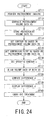
- the radiotherapy system 1A computes a difference d of the comparison point RQ included in the pretreatment volume data VQ aligned in step ST37 from the comparison point RP included in the treatment plan volume data VP (step ST38). As shown in Fig. 21 and Fig. 22 , the difference d computed in step ST38 is displayed through the display device 16 (step ST39).
- the radiotherapy system 1A controls the operations of the treatment controller 59 of the radiotherapy system 50 to treat the treatment site of the patient O (step ST40).
- the radiotherapy system 1A controls the operations of the bed controller 39 of the bed system 30 to retreat the table-top 33 from the radiotherapy system 50. Then, the patient O is removed from the table-top 33 of the bed system 30 of the radiotherapy system 1A.
- both the volume data VP and the volume data VQ can accurately be aligned with each other. Thus, proper treatment based on a treatment plan can be assisted.
- radiotherapy systems 1 and 1A of the embodiments have been described to facilitate understanding of the present invention and have not been described to limit the present invention. Therefore, each component disclosed in the radiotherapy systems 1 and 1A of the embodiments is intended to embrace all design modifications and equivalents within the technical scope of the present invention.
Abstract
Description
- Embodiments according to the present invention relate to a radiotherapy system and a control method for the radiotherapy system that can carry out radiotherapy.
- In radiotherapy, image data is generated by imaging during treatment planning, and treatment plan data is generated based on the image data. In addition, image data is generated by imaging just before the treatment. Then, the image data obtained just before the treatment is aligned with the image data for the treatment plan to compute a difference of the image data obtained just before the treatment from the image data for the treatment plan, and then repositioning is carried out by shifting the patient by the difference from the imaging position just before the treatment. After the repositioning, radiotherapy is carried out by irradiating a treatment site of the patient.
- Examples of conventional arts relating to the embodiments include Japanese Patent Application Publication (Laid-Open: KOKAI) No.
2010-69086 - However, according to the conventional arts, because both images are aligned with each other based on shading (CT values, image density, values of luminance, or the like) of overall data of both the images including sites unrelated to treatment, shift of internal organs in the data of both the images tends not to be taken into account and an area of interest such as a treatment site may not be aligned with high accuracy. In particular, in the case where chest and abdominal organs such as a lung, a liver, and the like are irradiated, because of respiratory movement of an affected part, a normal site other than a treatment site might be irradiated.
-
- [
Fig. 1] Fig. 1 is an external view diagram showing a part of a radiotherapy system of a first embodiment. - [
Fig. 2] Fig. 2 is a block diagram showing an entirety of the radiotherapy system of the first embodiment. - [
Fig. 3] Fig. 3 is a block diagram showing functions of the radiotherapy system of the first embodiment. - [
Fig. 4] Fig. 4 is a diagram schematically showing an example of a display image based on a treatment plan volume data. - [
Fig. 5] Fig. 5 is a diagram schematically showing an example of a display image based on a pretreatment volume data. - [
Fig. 6] Fig. 6 is a diagram schematically showing an example of a display image of a contour of an OAR based on the treatment plan volume data. - [
Fig. 7] Fig. 7 is a diagram showing general DV histograms of OARs as required regions. - [
Fig. 8] Fig. 8 is a diagram showing an example of a DV histogram of the contour of the OAR as the required region shown inFig. 6 . - [
Fig. 9] Fig. 9 is a drawing schematically showing an example of a display image of a contour of an OAR based on pretreatment volume data. - [
Fig. 10] Fig. 10 is a diagram showing an example of a DV histogram of the contour of the OAR shown inFig. 9 . - [
Fig. 11] Fig. 11 is a diagram showing the DV histogram shown inFig. 8 , the DV histogram shown inFig. 10 , and the difference in each volume. - [
Fig. 12] Fig. 12 is a diagram showing a general DV histogram of a PTV as a required region. - [
Fig. 13] Fig. 13 is a flowchart showing a first operation of the radiotherapy system of the first embodiment. - [
Fig. 14] Fig. 14 is a flowchart showing the first operation of the radiotherapy system of the first embodiment. - [
Fig. 15] Fig. 15 is a flowchart showing a second operation of the radiotherapy system of the first embodiment. - [
Fig. 16] Fig. 16 is a flowchart showing the second operation of the radiotherapy system of the first embodiment. - [
Fig. 17] Fig. 17 is a block diagram showing functions of the radiotherapy system of a second embodiment. - [
Fig. 18] Fig. 18 a diagram schematically showing an example of a display image based on the treatment plan volume data. - [
Fig. 19] Fig. 19 is a diagram schematically showing an example of a display image based on the pretreatment volume data. - [
Fig. 20] Fig. 20 is a diagram schematically showing an example of a display image based on an aligned pretreatment volume data. - [
Fig. 21] Fig. 21 is a diagram schematically showing a first display example of a difference of a comparison point. - [
Fig. 22] Fig. 22 is a diagram schematically showing a second display example of the difference of the comparison point. - [
Fig. 23] Fig. 23 is a flowchart showing the radiotherapy system of the second embodiment. - [
Fig. 24] Fig. 24 is a flowchart showing the radiotherapy system of the second embodiment. - Radiotherapy systems and control methods for the radiotherapy systems of the embodiments will be described with reference to the accompanying drawings.
- To solve the above-described problems, the present first embodiment provides the radiotherapy system includes: a placing unit configured to place a subject; an imaging unit configured to perform an imaging of the subject; a region setting unit configured to set a required region of first image data obtained by the imaging unit performing the imaging of the subject and to set a corresponding required region of second image data obtained by, before the imaging, performing a pre-imaging of the subject; a histogram generating unit configured to generate a dose-volume histogram of the required region of the first image data and to generate a dose-volume histogram of the required region of the second image data; a difference computing unit configured to compute a difference between the dose-volume histogram of the required region of the first image data and the dose-volume histogram of the required region of the second image data; and an outputting unit configured to, if it is determined that the difference is greater than a threshold value, output the determination to an outside.
- To solve the above-described problems, the present first embodiment provides the control method for the radiotherapy system includes: performing an imaging of a subject; setting a required region of first image data obtained by the imaging unit performing the imaging of the subject and setting a corresponding required region of second image data obtained by, before the imaging, performing a pre-imaging of the subject; generating a dose-volume histogram of the required region of the first image data and generating a dose-volume histogram of the required region of the second image data; computing a difference between the dose-volume histogram of the required region of the first image data and the dose-volume histogram of the required region of the second image data; and outputting the determination to an outside if it is determined that the difference is greater than a threshold value.
- To solve the above-described problems, the present second embodiment provides the radiotherapy system includes: a placing unit configured to place a subject; an imaging unit configured to perform an imaging of the subject; an image storage unit configured to store therein first image data obtained by performing a pre-imaging of the subject in radiotherapy planning; a region storage unit configured to store therein position information of a required region included in the first image data; and an image aligning unit configured to use the position information of the required region to align the first image data with second image data obtained by the imaging unit performing the imaging of the subject before radiotherapy.
- To solve the above-described problems, the present second embodiment provides the control method for the radiotherapy system includes: setting position information of a required region included in the first image data obtained by performing a pre-imaging of the subject in radiotherapy planning; and aligning the first image data with second image data obtained by the imaging unit performing the imaging of the subject before radiotherapy, using the position information.
-
Fig. 1 is an external view showing a part of a radiotherapy system of a first embodiment.Fig. 2 is a block diagram showing the entirety of the radiotherapy system of the first embodiment. -
Figs. 1 and2 show theradiotherapy system 1 of the first embodiment. Theradiotherapy system 1 includes aconsole 10, animaging system 20, abed system 30, atreatment planning system 40, and a radiotherapy system (linac: a radiotherapy system that carries out treatment by irradiation based on treatment plan data) 50. - As shown in
Fig. 1 , theimaging system 20, thebed system 30, and theradiotherapy system 50 are usually installed in an examination room. On the other hand, theconsole 10 is usually installed in a control room adjacent to the examination room. Thetreatment planning system 40 is installed outside the examination room and the control room. However, thetreatment planning system 40 may be installed in the control room or may be an integrated apparatus with theconsole 10. Also, representative examples of theimaging system 20 include an X-ray CT system, an MRI (magnetic resonance imaging) apparatus, and an X-ray apparatus. The following describes the case in which anX-ray CT system 20a is used as theimaging system 20. - As shown in
Fig. 2 , theconsole 10 of theradiotherapy system 1 has a computer-based configuration and is able to communicate with a trunk network of a hospital such as a LAN (local area network), not shown. Theconsole 10 is broadly composed of basic hardware such as a CPU (central processing unit) 11,main memory 12,image memory 13, an HDD (hard disc drive) 14, aninput device 15, and adisplay device 16. TheCPU 11 and each hardware component of theconsole 10 are connected with each other via buses as common signal transmission paths. In addition, theconsole 10 may include a recording medium drive. - The
CPU 11 is a control device having a configuration of an integrated circuit (LSI) in which an electronic circuit composed of a semiconductor is housed in a package with multiple terminals. If an instruction is input by an operator such as a physician operating theinput device 15, theCPU 11 executes a program stored in themain memory 12. Alternatively, theCPU 11 loads a program stored in theHDD 14, a program transferred from the network and installed in theHDD 14, or a program read out from a recording medium mounted in a recording medium drive (not shown) and installed in theHDD 14, into themain memory 12 to execute the program. - The
main memory 12 is a storage device that includes ROM (read only memory), RAM (random access memory), or the like. Themain memory 12 is used for storage of IPL (initial program loading), a BIOS (basic input/output system), and data. Also, themain memory 12 is used as working memory for theCPU 11 and to temporarily store data. - The
image memory 13 is a storage device in which slice data as two-dimensional image data and treatment plan volume data and pretreatment volume data as three-dimensional image data are stored. - The
HDD 14 is a storage device containing undetachable metal disks on which a magnetic substance is applied or evaporated. The HDD 14 is a storage device in which programs installed in the console 10 (in addition to application programs, including an OS (operating system)) and data are stored. In addition, the OS may be allowed to provide a GUI (graphical user interface) that makes heavy use of graphics in information displayed on thedisplay device 16 so that an operator such as an operational person can perform basic operations through theinput device 15. - The
input device 15 is a pointing device that can be operated by the operator and input signals according to operations are sent to theCPU 11. - The
display device 16 includes an image combining circuit, VRAM (video random access memory), and a display that are not shown. The image combining circuit generates composite data into which character data of a variety of parameters is combined with image data. The VRAM expands the composite data into display image data to be displayed on the display. The display is composed of a liquid crystal display, a CRT (cathode ray tube), or the like, and sequentially displays items of the display image data as display images. - The
console 10 controls operations of anX-ray CT system 20a, abed system 30, and aradiotherapy system 50. Theconsole 10 also performs correction processing (preprocessing) such as logarithmic transformation processing and sensitivity correction on raw data input from aDAS 24 of theX-ray CT system 20a to generate projection data, and generates slice data as two-dimensional image data and volume data as three-dimensional image data on the basis of the projection data. - To display image data of a region including a treatment site of a cancer, a tumor, or the like of a patient (subject) O, the
X-ray CT system 20a of theradiotherapy system 1 images the region including the treatment site. TheX-ray CT system 20a includes anX-ray tube 21 as a radiation source, anaperture 22, anX-ray detector 23, the DAS (data acquisition system) 24, arotation portion 25, a high voltage supplying device 26, anaperture driving device 27, arotation driving device 28, and animaging controller 29. - The
X-ray tube 21 causes an electron beam to collide with a metal target according to tube voltage supplied from the high voltage supplying device 26 to generate bremsstrahlung X-rays, and applies the X-rays to theX-ray detector 23. The X-rays applied from theX-ray tube 21 form fan beam X-rays and cone beam X-rays. - Using the
aperture driving device 27, theaperture 22 adjusts an area being irradiated with the X-rays by theX-ray tube 21. That is, the X-ray irradiated area can be modified by theaperture driving device 27 adjusting an opening of theaperture 22. - The
X-ray detector 23 is a matrix form X-ray detector, that is, theX-ray detector 23 is a two-dimensional array type X-ray detector (also referred to as a multi-slice type sensor) having a plurality of channels in a channel direction and a plurality of rows of X-ray detecting elements in a slice direction. The X-ray detecting elements of theX-ray detector 23 detect the X-rays applied from theX-ray tube 21. - The
DAS 24 amplifies a signal of transmission data detected by each X-ray detecting element of theX-ray detector 23 to convert the signal into a digital signal. Output data of theDAS 24 is supplied to theconsole 10 through theimaging controller 29. - The
rotation portion 25 holds theX-ray tube 21, theaperture 22, theX-ray detector 23, and theDAS 24 as a single unit. Therotation portion 25 can rotate about the patient O with theX-ray tube 21, theaperture 22, theX-ray detector 23, and theDAS 24 as a single unit and with theX-ray tube 21 and theX-ray detector 23 opposing each other. It is assumed that a direction parallel to an axis of rotation of therotation portion 25 is defined as a z axis direction, and a plane orthogonal to the z axis direction is defined as an x axis direction and a y axis direction. - The high voltage supplying device 26 supplies the
X-ray tube 21 with power required for X-ray irradiation in response to control of theimaging controller 29. - The
aperture driving device 27 has a mechanism that uses theaperture 22 to adjust an area irradiated with X-rays in the slice direction in response to control of theimaging controller 29. - The
rotation driving device 28 has a mechanism that, in response to control of theimaging controller 29, rotates therotation portion 25 about a cavity portion (not shown) with a position relationship of therotation portion 25 maintained. - The
imaging controller 29 comprises a CPU and a memory. Theimaging controller 29 controls theX-ray tube 21, theX-ray detector 23, theDAS 24, the high voltage supplying device 26, theaperture driving device 27, and therotation driving device 28 to perform a scan with the operations of thebed system 30. - The
bed system 30 of theradiotherapy system 1 includes a table-top driving device 32, a table-top 33, and abed controller 39. - The patient O can be placed on the table-
top 33. The table-top driving device 32 has a mechanism that moves the table-top 33 up and down along the y axis direction and moves the table-top 33 backward and forward along the z axis direction in response to control of thebed controller 39. The table-top driving device 32 also has a mechanism that rotates the table-top 33 about the y axis direction in response to control of thebed controller 39. - The
bed controller 39 comprises a CPU and a memory. Thebed controller 39 controls the table-top driving device 32 to perform a scan with the operations of theX-ray CT system 20a. Thebed controller 39 also controls the table-top driving device 32 to perform radiotherapy with the operations of theradiotherapy system 50. - The
treatment planning system 40 of theradiotherapy system 1 generates treatment plan data for radiotherapy to be carried out by theradiotherapy system 50 on the basis of the slice data and the volume data generated by theconsole 10 after imaged by theX-ray CT system 20a. Under the control of theconsole 10 based on the treatment plan data generated by thetreatment planning system 40, a site to be treated of the patient O is irradiated by theradiotherapy system 50. Thetreatment planning system 40 has a computer-based configuration and can communicate with the trunk network of the hospital such as a LAN, not shown. Thetreatment planning system 40 is broadly composed of basic hardware such as aCPU 41,main memory 42,treatment plan memory 43, anHDD 44, aninput device 45, and adisplay device 46. TheCPU 41 and each hardware component of thetreatment planning system 40 are connected with each other via buses as common signal transmission paths. In addition, thetreatment planning system 40 may include a recording medium drive. - A configuration of the
CPU 41 is equivalent to that of theCPU 11 of theconsole 10. If the operator operates theinput device 45 to input an instruction, theCPU 41 executes a program stored in themain memory 42. Alternatively, theCPU 41 loads a program stored in theHDD 44, a program transferred from the network and installed in theHDD 44, or a program read out from a recording medium mounted in a recording medium drive (not shown) and installed in theHDD 44, into themain memory 42 to execute the program. - A configuration of the
main memory 42 is equivalent to that of themain memory 12 of theconsole 10. Themain memory 42 is used for storage of IPL, a BIOS, and data. Also, themain memory 42 is used as working memory for theCPU 41 and to temporarily store data. - The
treatment plan memory 43 is a storage device in which treatment plan data is stored. - A configuration of the
HDD 44 is equivalent to that of theHDD 14 of theconsole 10. - A configuration of the
input device 45 is equivalent to that of theinput device 15 of theconsole 10. - A configuration of the
display device 46 is equivalent to that of thedisplay device 16 of theconsole 10. - The
treatment planning system 40 determines a position of the treatment site of the patient O and a shape of the treatment site based on the image data generated by theX-ray CT system 20a, and also determines a type of radiation (an X-ray, an electron beam, a neutron beam, a proton beam, a heavy particle beam, or the like) to be applied to the treatment site, energy of the radiation, and a radiation field. - The
radiotherapy system 50 of theradiotherapy system 1 can generally generate radiation in the MV range. Theradiotherapy system 50 is provided with the aperture (collimator) at a radiation generation port, and the aperture provides an irradiation shape and a dose distribution that are based on the treatment plan. In recent years, multileaf collimators (MLCs) that can form dose distributions corresponding to complex shapes of tumors by a plurality of movable leaves have been often used as the apertures. Theradiotherapy system 50 adjusts an irradiation amount with a radiation field formed by the aperture and eliminates or reduces a treatment site of the patient O. A combination of theX-ray CT system 20a, thebed system 30, and theradiotherapy system 50 is called a "linac-CT." - The
radiotherapy system 50 includes aradiation source 51 as a radiation source, anaperture 52, anarm portion 55, a highvoltage supplying device 56, anaperture driving device 57, arotation driving device 58, and atreatment controller 59. - The
radiation source 51 generates radiation according to tube voltage supplied from the highvoltage supplying device 56. - Using the
aperture driving device 57, theaperture 52 adjusts an area being irradiated by theradiation source 51. That is, the irradiated area can be modified by theaperture driving device 57 adjusting an opening of theaperture 52. - The
arm portion 55 holds theradiation source 51 and theaperture 52 as a single unit. Thearm portion 55 can rotate about the patient O with theradiation source 51 and theaperture 52 as a single unit. - The high
voltage supplying device 56 supplies theradiation source 51 with power required for irradiation in response to control of thetreatment controller 59. - The
aperture driving device 57 has a mechanism that uses theaperture 52 to adjust an irradiated area in response to control of thetreatment controller 59. - The
rotation driving device 58 has a mechanism that rotates thearm portion 55 about a connection portion (not shown) between thearm portion 55 and a supporting portion (not shown) in response to control of thetreatment controller 59. - The
treatment controller 59 comprises a CPU and a memory. Thetreatment controller 59 controls, in accordance with the treatment plan data generated by thetreatment planning system 40, theradiation source 51, the highvoltage supplying device 56, and theaperture driving device 57 to perform irradiation for treatment with the operations of thebed system 30. -
Fig. 3 is a block diagram showing functions of theradiotherapy system 1 of the first embodiment. - The
CPU 11 of theconsole 10 and theCPU 41 of thetreatment planning system 40 execute programs, and thereby as shown inFig. 3 , theradiotherapy system 1 functions as animaging performing unit 61, an imagedata generating unit 62, a treatment plandata generating unit 63, aninterface unit 64, acontour setting unit 65, aninterface unit 66, a DVH (dose-volume histogram) computing unit 67, a dosedifference computing unit 68, a thresholdvalue determining unit 69, areporting control unit 70, and atreatment performing unit 71. All or a part of thecomponents 61 to 71 of theradiotherapy system 1 may be included in theradiotherapy system 1 as hardware. - The
imaging performing unit 61 of theconsole 10 has a function of controlling the operations of theimaging controller 29 of theX-ray CT system 20a and thebed controller 39 of thebed system 30 to, for a treatment plan, image a region including a treatment site of the patient O. Also, theimaging performing unit 61 has a function of controlling the operations of theimaging controller 29 of theX-ray CT system 20a and thebed controller 39 of thebed system 30 to image the region including the treatment site of the patient O after the treatment planning, for example, just before the treatment. - The image
data generating unit 62 of theconsole 10 has a function of generating slice data as two-dimensional image data by theimaging performing unit 61 performing processing such as image reconstructing processing on the transmission data obtained by theX-ray CT system 20a. Also, the imagedata generating unit 62 has a function of generating volume data as three-dimensional image data based on the slice data corresponding to a plurality of slices. Specifically, the imagedata generating unit 62 generates the slice data by imaging it for a treatment plan and generates the volume data (treatment plan volume data) VP for the treatment plan for thetreatment planning system 40. On the other hand, the imagedata generating unit 62 generates slice data by imaging it just before the treatment by theradiotherapy system 50 and generates volume data (pretreatment volume data) VQ obtained just before the treatment. Each of the volume data VP and the volume data VQ generated by the imagedata generating unit 62 is stored in a storage device such as theimage memory 13. -
Fig. 4 is a diagram schematically showing an example of a display image based on the treatment plan volume data VP.Fig. 5 is a diagram schematically showing an example of a display image based on the pretreatment volume data VQ. -
Fig. 4 shows a display image based on the treatment plan volume data VP.Fig. 5 shows a display image based on the pretreatment volume data VQ. If the display image shown inFig. 4 is compared with the display image shown inFig. 5 , it can be seen that there is a difference between the volume data VP and the volume data VQ in structure images corresponding to the structure of the patient O. - The treatment plan
data generating unit 63 of thetreatment planning system 40 shown inFig. 3 has a function of setting a treatment plan by setting irradiation conditions such as a direction and number of irradiation, and a radiation intensity with a contour of a body of the patient O and a region of an affected part taken into consideration based on the treatment plan volume data VP stored in theimage memory 13, to generate treatment plan data. When generating the treatment plan data, the treatment plandata generating unit 63 sets, on the basis of the treatment plan volume data VP, a required area, for example, a contour SP of an OAR (organ at risk) not to be irradiated. For example, the treatment plandata generating unit 63 sets the contour SP of the OAR through theinterface unit 64. The contour SP of the OAR set by the treatment plandata generating unit 63 is three-dimensional position information. When setting a contour SP of an OAR, the treatment plandata generating unit 63 may set a contour SP1 of only one OAR or may set contours SP1 SP2, ... of a plurality of OARs. In addition, when generating the treatment plan data, the treatment plandata generating unit 63 may set a comparison point (isocenter).Fig. 6 is a diagram schematically showing an example of a display image of a contour SP of an OAR based on the treatment plan volume data VP. - In addition, when generating the treatment plan data, the treatment plan
data generating unit 63 computes a DV histogram HP of the OAR based on the set contour SP of the OAR. The DV histogram computed by the treatment plandata generating unit 63 is a graph of relationship between dose and volume in a required region and is used for comparative evaluation of a plurality of items of treatment plan data.Fig. 7 is a diagram showing general DV histograms of OARs (a rectum and a gallbladder) as required regions. In addition,Fig. 8 is a diagram showing an example of a DV histogram HP of the contour SP of the OAR as the required region shown inFig. 6 . - It should be noted that it is assumed that the treatment plan
data generating unit 63 generates the treatment plan data based on the treatment plan volume data VP generated by theX-ray CT system 20a included in theradiotherapy system 1, but the treatment plandata generating unit 63 is not limited thereto. The treatment plandata generating unit 63 may generate the treatment plan data based on treatment plan volume data generated by an imaging system external to theradiotherapy system 1. The treatment plan data generated by the treatment plandata generating unit 63 is stored in a storage device such as thetreatment plan memory 43. - The
interface unit 64 of thetreatment planning system 40 is an interface such as a GUI that displays on the display device 46 a display image that is based on the treatment plan volume data VP and enables, on the display image, the operator to select the contour SP of the OAR through theinput device 45 operated by the operator. - The
contour setting unit 65 of theconsole 10 has a function of setting, on the basis of the pretreatment volume data VQ stored in theimage memory 13, a contour SQ of the OAR corresponding to the contour SP of the OAR stored in thetreatment plan memory 43. For example, thecontour setting unit 65 sets the contour SQ of the OAR through theinterface unit 66. Alternatively, thecontour setting unit 65 aligns the volume data VP with the volume data VQ to set the contour SQ of the OAR corresponding to the contour SP of the OAR stored in thetreatment plan memory 43. An aligning method may be a method for aligning the entire volume data VP with the entire volume data VQ so as to decrease a difference in CT values (image density, values of luminance, and the like) between the volume data VP and the volume data VQ, or may be a method for aligning the entire volume data VP with the entire volume data VQ using "non-rigid bodies" linked with modification and shift of the volume data VP and the volume data VQ. - When setting the contour SQ of the OAR, the
contour setting unit 65 sets only a contour SQ of one OAR (SQ1) if only a contour SP of one OAR (SP1) is set, and sets contours SQ of a plurality of OARs (SQ1, SQ2, ...) if contours SP of a plurality of OARs (SP1, SP2, ...) are set.Fig. 9 is a drawing schematically showing an example of a display image of a contour SQ of an OAR based on the pretreatment volume data VQ. - The
interface unit 66 of theconsole 10 is an interface such as a GUI that displays on the display device 16 a display image that is based on the pretreatment volume data VQ stored in theimage memory 13 and enables, on the display image, the operator to select the contour SQ through theinput device 15 operated by the operator. - The DVH computing unit 67 of the
console 10 has a function of computing a DV histogram HQ of the OAR based on the contour SQ of the OAR set by thecontour setting unit 65. The DV histogram HQ of the OAR computed by the DVH computing unit 67 is displayed on thedisplay device 16 through theinterface unit 66.Fig. 10 is a diagram showing an example of the DV histogram HQ of the contour SQ of the OAR shown inFig. 9 . - The dose
difference computing unit 68 of theconsole 10 has a function of computing a difference D between doses in the same volume on the basis of the DV histogram HP stored in thetreatment plan memory 43 and the DV histogram HQ computed by the DVH computing unit 67. That is, the dosedifference computing unit 68 computes a difference D between the DV histograms HP and HQ in each volume.Fig. 11 is a diagram showing the DV histogram HP shown inFig. 8 , the DV histogram HQ shown inFig. 10 , and the difference D in each volume. - The threshold
value determining unit 69 of theconsole 10 has a function of determining whether or not the difference D in each volume computed by the dosedifference computing unit 68 is equal to or smaller than a threshold value. For example, the thresholdvalue determining unit 69 determines whether or not a maximum difference Dmax (shown inFig. 11 ) of the difference D in each of the volumes is equal to or smaller than a threshold value. If the maximum difference Dmax is greater than the threshold value, a position of the patient O seen when the treatment plan volume data VP is generated (during the imaging) is significantly different from a position of the patient O seen when the pretreatment volume data VQ is generated (during the imaging). Therefore, if theradiotherapy system 50 subsequently carries out irradiation, a position different from the position determined in the treatment planning is actually irradiated. - The
reporting control unit 70 has a function of, if the thresholdvalue determining unit 69 determines that the maximum difference Dmax is greater than the threshold value, reporting (output) an abnormality to the operator. For example, thereporting control unit 70 reports an abnormality to the operator through thedisplay device 16. - The
treatment performing unit 71 of theconsole 10 has a function of, if the thresholdvalue determining unit 69 determines that a difference D is equal to or smaller than the threshold value, controlling the operations of thetreatment controller 59 of theradiotherapy system 50 and the operations of thebed controller 39 of thebed system 30 to treat a treatment site of the patient O. - It should be noted that the contour SP of the required region set by the treatment plan
data generating unit 63 and thecontour setting unit 65 is not limited to a contour SP of an OAR. The contour SP of the required region set by the treatment plandata generating unit 63 and thecontour setting unit 65 may be a contour SP of a PTV (planning target volume) as a treatment site.Fig. 12 is a diagram showing a general DV histogram of a PTV as a required region. - Next, a first operation of the
radiotherapy system 1 of the first embodiment will be described using flow charts shown inFig. 13 andFig. 14 . - If the patient O is placed on the table-
top 33 of thebed system 30 of theradiotherapy system 1, theradiotherapy system 1 controls the operations of thebed controller 39 of thebed system 30 to insert the table-top 33 into an opening of theX-ray CT system 20a. Then, as shown inFig. 13 , theradiotherapy system 1 controls the operations of theimaging controller 29 of theX-ray CT system 20a to image a region including the treatment site of the patient O for treatment planning (step ST1). Then, theradiotherapy system 1 performs processing such as image reconstructing processing on transmission data obtained by theX-ray CT system 20a in step ST1 to generate slice data as two-dimensional image data, and generates treatment plan volume data VP as three-dimensional image data based on the slice data corresponding to a plurality of slices (step ST2). The treatment plan volume data VP generated in step ST2 is stored in a storage device such as the image memory 13 (step ST3). - The
radiotherapy system 1 sets a treatment plan by setting irradiation conditions such as a direction and number of irradiation, and a radiation intensity with a contour of a body of the patient O and a region of an affected part taken into consideration based on the treatment plan volume data VP stored in theimage memory 13 in step ST3, to generate treatment plan data (step ST4). In step ST4, theradiotherapy system 1 sets a contour SP of an OAR as a required region based on the treatment plan volume data VP (step ST4a). In step ST4, theradiotherapy system 1 also computes a DV histogram HP of the contour SP of the OAR set in step ST4a (step ST4b). The treatment plan data generated in step ST4 is stored in a storage device such as the treatment plan memory 43 (step ST5). - When the imaging of the region including the treatment site of the patient O ends in step ST1, the
radiotherapy system 1 controls the operations of thebed controller 39 of thebed system 30 to retreat the table-top 33 from the opening of theX-ray CT system 20a. Then, the patient O is removed from the table-top 33 of thebed system 30 of theradiotherapy system 1. - If the patient O is placed on the table-
top 33 of thebed system 30 of theradiotherapy system 1 just before the treatment is performed by theradiotherapy system 50, theradiotherapy system 1 controls the operations of thebed controller 39 of thebed system 30 to insert the table-top 33 into the opening of theX-ray CT system 20a. Then, as shown inFig. 14 , theradiotherapy system 1 controls the operations of theimaging controller 29 of theX-ray CT system 20a to image the region including the treatment site of the patient O just before the treatment (step ST11). Then, theradiotherapy system 1 performs processing such as image reconstructing processing on transmission data obtained by theX-ray CT system 20a in step ST11 to generate slice data as two-dimensional image data, and generates pretreatment volume data VQ as three-dimensional image data based on the slice data corresponding to a plurality of slices (step ST12). The pretreatment volume data VQ generated in step ST12 is stored in a storage device such as the image memory 13 (step ST13). - The
radiotherapy system 1 sets a contour SQ of the OAR corresponding to the contour SP of the OAR stored in thetreatment plan memory 43 based on the pretreatment volume data VQ stored in theimage memory 13 in step ST13 (step ST14). Theradiotherapy system 1 also computes a DV histogram HQ of the contour SQ of the OAR based on the treatment plan set in step ST4 and the contour SQ of the OAR set in step ST14 (step ST15). - Then, the
radiotherapy system 1 computes differences D between doses in the same volumes based on the DV histogram HP of the contour SP of the OAR set in step ST4b inFig. 13 and the DV histogram HQ of the contour SQ of the OAR set in step ST15 (step ST16). - Then, the
radiotherapy system 1 determines whether or not a maximum difference Dmax of the difference D in each of the volumes computed in step ST16 is equal to or smaller than a threshold value (step ST17). If yes in step ST17, that is, if it is determined that the maximum difference Dmax of the difference D in each of the volumes is equal to or smaller than the threshold value, theradiotherapy system 1 allows for processing in a next step, the step ST19 (step ST18). - Then, the
radiotherapy system 1 controls the operations of thetreatment controller 59 of theradiotherapy system 50 to treat the treatment site of the patient O (step ST19). After the treatment site of the patient O is treated in step ST19, theradiotherapy system 1 controls the operations of thebed controller 39 of thebed system 30 to retreat the table-top 33 from theradiotherapy system 50. Then, the patient O is removed from the table-top 33 of thebed system 30 of theradiotherapy system 1. - On the other hand, if no in step ST17, that is, if it is determined that the maximum difference Dmax of the difference D in each of the volumes is greater than the threshold value, the
radiotherapy system 1 reports an abnormality to the operator (step ST20). For example, in step ST20, theradiotherapy system 1 reports an abnormality to the operator through thedisplay device 16. Then, after a setting is carried out again by shifting the patient O on the table-top 33 (step ST21), theradiotherapy system 1 performs the pretreatment imaging (step ST11). - Next, a second operation of the
radiotherapy system 1 of the first embodiment will be described using flow charts shown inFig. 15 andFig. 16 . In the second operation of theradiotherapy system 1 shown inFig. 15 andFig. 16 , the same reference numerals are used for denoting the same steps as those in the first operation of theradiotherapy system 1 shown inFig. 13 andFig. 14 and descriptions thereof are omitted. - If the
radiotherapy system 1 reports the abnormality to the operator in step ST20, thetreatment planning system 40 reconsiders the treatment plan set in step ST4 and sets a treatment plan again (step ST31). For example, in step ST31, with the treatment plan set in step ST4 as an initial setting, the irradiation conditions such as a direction and number of irradiation, and radiation intensity are set again. Then, theradiotherapy system 1 computes a DV histogram HQ of the contour SQ of the OAR based on the treatment plan set again in step ST31 and the contour SQ of the OAR set in step ST14 (step ST15), and the processing proceeds to a step ST16. - In addition, the
radiotherapy system 1 may also compute the DV histogram HQ of the contour SQ of the OAR associated with the irradiation conditions simultaneously as the irradiation conditions are set again in step ST31 to immediately display the DV histogram HQ. In this case, it is suitable to display the DV histogram HP computed in step ST4b with the DV histogram HQ, which is immediately displayed. The operator can judge suitability by comparing the immediately displayed DV histogram HQ with the DV histogram HP to allow for the processing in step ST19 without stopping by the step ST17. - According to the
radiotherapy system 1 of the first embodiment, the DV histogram HP of the contour SP of the OAR or the like included in the treatment plan volume data VP is compared with the DV histogram HQ of the contour SQ of the OAR or the like included in the pretreatment volume data VQ, and if a difference therebetween is significant, the fact that a setting of the patient O is required again to carry out treatment based on a treatment plan can be reported to the operator. Thus, according to theradiotherapy system 1, proper treatment based on a treatment plan can be assisted. - Also, according to the
radiotherapy system 1 of the first embodiment, proper treatment can be assisted by setting a treatment plan again. - An external view of a
radiotherapy system 1A of a second embodiment is similar to the external view of theradiotherapy system 1 of the first embodiment shown inFig. 1 and an entire configuration of theradiotherapy system 1A of the second embodiment is similar to the entire configuration of theradiotherapy system 1 of the first embodiment shown inFig. 2 , so that descriptions thereof are omitted. -
Fig. 17 is a block diagram showing functions of theradiotherapy system 1A of the second embodiment. - The
CPU 11 of theconsole 10 and theCPU 41 of thetreatment planning system 40 execute programs, and thereby as shown inFig. 17 , theradiotherapy system 1A functions as theimaging performing unit 61, the imagedata generating unit 62, a treatment plandata generating unit 83, aninterface unit 84, acontour setting unit 85, aninterface unit 86, a comparison point (reference point)setting unit 87, a specificcontour setting unit 88, a aligningunit 89, adifference computing unit 90, and atreatment performing unit 91. All or a part of thecomponents radiotherapy system 1A may be included in theradiotherapy system 1A as hardware. - In the
radiotherapy system 1A shown inFig. 17 , the same reference numerals are used for denoting the same functions as those in theradiotherapy system 1 shown inFig. 3 and descriptions thereof are omitted. - The treatment plan
data generating unit 83 of thetreatment planning system 40 has a function of generating treatment plan data based on the treatment plan volume data VP stored in theimage memory 13. When generating the treatment plan data, the treatment plandata generating unit 83 sets, on the basis of the treatment plan volume data VP, a contour SP for a structure region corresponding to structure in the patient O and sets a comparison point (isocenter) RP. The structure in the patient O includes a PTV as a treatment site, an OAR not to be irradiated, other internal organs, bones, and the like. For example, the treatment plandata generating unit 83 sets the contour SP and the comparison point RP through theinterface unit 84. The contour SP and the comparison point RP set by the treatment plandata generating unit 83 are three-dimensional position information. When setting the contour SP, the treatment plandata generating unit 83 may set only one contour SP1 or may set a plurality of contours SP1, SP2... - It should be noted that it is assumed that the treatment plan
data generating unit 83 generates the treatment plan data based on the treatment plan volume data VP generated by theX-ray CT system 20a included in theradiotherapy system 1A, but the treatment plandata generating unit 83 is not limited thereto. The treatment plandata generating unit 83 may generate the treatment plan data based on treatment plan volume data generated by an imaging system external to theradiotherapy system 1A. The treatment plan data generated by the treatment plandata generating unit 83 is stored in a storage device such as thetreatment plan memory 43. - The
interface unit 84 of thetreatment planning system 40 is an interface such as a GUI that displays a display image that is based on the treatment plan volume data VP on thedisplay device 46 and enables, on the display image, the operator to select the contour SP and the comparison point RP through theinput device 45 operated by the operator. - The
contour setting unit 85 of theconsole 10 has a function of setting, on the basis of the pretreatment volume data VQ stored in theimage memory 13, a contour SQ corresponding to the contour SP stored in thetreatment plan memory 43. For example, thecontour setting unit 85 sets the contour SQ through theinterface unit 86. When setting the contour SQ, thecontour setting unit 85 sets only one contour SQ (SQ1) if only one contour SP (SP1) is set, and sets a plurality of contours SQ (SQ1, SQ2, ...) if a plurality of contours SP (SP1, SP2, ...) are set. - The
interface unit 86 of theconsole 10 is an interface such as a GUI that displays on the display device 16 a display image that is based on the pretreatment volume data VQ stored in theimage memory 13 and enables, on the display image, the operator to select the contour SQ through theinput device 15 operated by the operator. - The comparison
point setting unit 87 of theconsole 10 has a function of setting a comparison point RQ based on the pretreatment volume data VQ stored in theimage memory 13. For example, the comparisonpoint setting unit 87 sets the comparison point RQ through theinterface unit 86. Theinterface unit 86 is an interface such as a GUI that displays on the display device 16 a display image that is based on the pretreatment volume data VQ stored in theimage memory 13 and enables, on the display image, the operator to select the comparison point RQ through theinput device 15 operated by the operator. - The specific
contour setting unit 88 of theconsole 10 has a function of setting a specific contour s to be aligned, on the basis of the contour SP (one contour SP1, or a plurality of contours SP1, SP2, ...) stored in thetreatment plan memory 43 and the contour SQ (one contour SQ1, or a plurality of contours SQ1, SQ2, ...) set by thecontour setting unit 85. Examples of the specific contours include contours of a PTV and an OAR. If the plurality of contours SP and the plurality of contours SQ corresponding thereto are set, the specificcontour setting unit 88 may set one or more corresponding specific contours s of the contours SP and the contours SQ. - For example, the specific
contour setting unit 88 sets a specific contour s through theinterface unit 86. Theinterface unit 86 is an interface such as a GUI that displays on thedisplay device 16 display images that are based on the volume data VP and the volume data VQ including the contours SP and SQ and enables, on the display images, the operator to select the specific contour s through theinput device 15 operated by the operator. Also, for example, theconsole 10 registers identifiers of a PTV and the like in advance, and thereby the specificcontour setting unit 88 may also set specific contours s corresponding to the registered identifiers. - In addition, when setting a specific contour s, the specific
contour setting unit 88 may set only one specific contour s (s1) or may set a plurality of specific contours sn (s1, s2, ...). When setting the specific contours sn, it is desirable that the specificcontour setting unit 88 should prioritize the specific contours sn for aligning. -
Fig. 18 a diagram schematically showing an example of a display image based on the treatment plan volume data VP.Fig. 19 is a diagram schematically showing an example of a display image based on the pretreatment volume data VQ. -
Fig. 18 shows a PTV as a specific contour s1 and an OAR as a specific contour s2 of a plurality of contours SP included in a display image based on the treatment plan volume data VP.Fig. 19 is a diagram showing a PTV as a specific contour s1 and an OAR as a specific contour s2 of a plurality of contours SQ included in a display image based on the pretreatment volume data VQ. If the display image shown inFig. 18 is compared with the display image shown inFig. 19 , it can be seen that there is a difference between the volume data VP and the volume data VQ. InFig. 18 and Fig. 19 , the specificcontour setting unit 88 sets two specific contours s1 and s2 based on the contour SP of the treatment plan volume data VP and the contour SQ of the pretreatment volume data VQ. - The aligning
unit 89 of theconsole 10 shown inFig. 17 has a function of relatively aligning the entire volume data VP with the entire volume data VQ on the basis of the specific contour s included in the treatment plan volume data VP set by the specificcontour setting unit 88 and the specific contours included in the pretreatment volume data VQ. An aligning method of the aligningunit 89 may be a method for aligning the entire volume data VP with the entire volume data VQ so as to decrease a difference in CT values (image density, values of luminance, and the like) between the specific contours s, or may be a method for aligning the entire volume data VP with the entire volume data VQ using "non-rigid bodies" linked with modification and shift of the specific contours s. - In addition, in the case shown in
Fig. 18 and Fig. 19 , if the priority of the PTV as the specific contour s1 is higher than that of the OAR as the specific contour s2, the specific aligningunit 89 relatively aligns the entire volume data VP with the entire volume data VQ on the basis of the PTV of the treatment plan volume data VP and the PTV of the pretreatment volume data VQ.Fig. 20 is a diagram schematically showing an example of a display image based on an aligned pretreatment volume data VQ. - The
difference computing unit 90 of theconsole 10 has a function of computing a difference (at least one of a deviation and a deviation direction in a three-dimensional coordinate system) d of the comparison point RQ included in the pretreatment volume data VQ aligned by the aligningunit 89 from the comparison point RP included in the aligned treatment plan volume data VP. The difference d computed by thedifference computing unit 90 is displayed on thedisplay device 16 through theinterface unit 86. -
Fig. 21 is a diagram schematically showing a first display example of a difference d of a comparison point RQ.Fig. 22 is a diagram schematically showing a second display example of the difference d of the comparison point RQ. -
Fig. 21 shows a case in which both a deviation and a deviation direction as a difference d of the comparison point RQ are displayed in a three-dimensional coordinate system.Fig. 22 shows a case in which both the deviation and the deviation direction as the difference d of the comparison point RQ are displayed in a two-dimensional coordinate system. Displaying the comparison points RP and RQ as shown inFig. 21 andFig. 22 enables the operator to visually identify the difference d of the comparison point RQ. - The
treatment performing unit 91 of theconsole 10 shown inFig. 17 has a function of controlling the operations of thetreatment controller 59 of theradiotherapy system 50 and thebed controller 39 of thebed system 30 to treat the treatment site of the patient O after thetreatment planning system 40 reconsiders the treatment plan based on the display of the difference d of the comparison point RQ or after a setting is performed again by shifting the patient O on the table-top 33 by the difference d. - Next, an operation of the
radiotherapy system 1A of the second embodiment will be described using flow charts shown inFig. 23 andFig. 24 . In the operation of theradiotherapy system 1A shown inFig. 23 andFig. 24 , the same reference numerals are used for denoting the same steps as those in the operation of theradiotherapy system 1 shown inFig. 13 andFig. 14 and descriptions thereof are omitted. - The
radiotherapy system 1A sets a contour SQ corresponding to the contour SP stored in thetreatment plan memory 43 based on the pretreatment volume data VQ stored in theimage memory 13 in step ST13 (step ST14). Theradiotherapy system 1A also sets a comparison point RQ based on the pretreatment volume data VQ stored in theimage memory 13 in step ST13 (step ST35). - Then, the
radiotherapy system 1A sets a specific contours to be aligned on the basis of the contour SP set in step ST4a ofFig. 23 and the contour SQ set in step ST14 (step ST36). Examples of the specific contours include contours of a PTV and an OAR. - Then, the
radiotherapy system 1A relatively aligns the entire volume data VP with the entire volume data VQ on the basis of the specific contour s included in the treatment plan volume data VP and the specific contour s included in the pretreatment volume data VQ, both set in step ST36 (step ST37). - Then, the
radiotherapy system 1A computes a difference d of the comparison point RQ included in the pretreatment volume data VQ aligned in step ST37 from the comparison point RP included in the treatment plan volume data VP (step ST38). As shown inFig. 21 andFig. 22 , the difference d computed in step ST38 is displayed through the display device 16 (step ST39). - Then, after the
treatment planning system 40 reconsiders the treatment plan based on the difference d display in step ST39 or after a setting is performed again by shifting the patient O on the table-top 33 by the difference d, theradiotherapy system 1A controls the operations of thetreatment controller 59 of theradiotherapy system 50 to treat the treatment site of the patient O (step ST40). - After the treatment site of the patient O is treated in step ST40, the
radiotherapy system 1A controls the operations of thebed controller 39 of thebed system 30 to retreat the table-top 33 from theradiotherapy system 50. Then, the patient O is removed from the table-top 33 of thebed system 30 of theradiotherapy system 1A. - According to the
radiotherapy system 1A of the second embodiment, since the entire treatment plan volume data VP is aligned with the entire pretreatment volume data VQ on the basis of the specific contour s included in both the volume data VP and the volume data VQ, both the volume data VP and the volume data VQ can accurately be aligned with each other. Thus, proper treatment based on a treatment plan can be assisted. - It should be noted that the
radiotherapy systems radiotherapy systems - Further embodiments are set out in the following clauses:
- 1. A radiotherapy system comprising:
- a placing unit configured to place a subject;
- an imaging unit configured to perform an imaging of the subject;
- a region setting unit configured to set a required region of first image data obtained by the imaging unit performing the imaging of the subject and to set a corresponding required region of second image data obtained by, before the imaging, performing a pre-imaging of the subject;
- a histogram generating unit configured to generate a dose-volume histogram of the required region of the first image data and to generate a dose-volume histogram of the required region of the second image data;
- a difference computing unit configured to compute a difference between the dose-volume histogram of the required region of the first image data and the dose-volume histogram of the required region of the second image data; and
- an outputting unit configured to, if it is determined that the difference is greater than a threshold value, output the determination to an outside.
- 2. The radiotherapy system according to
clause 1, wherein
if it is determined that a maximum difference of a difference in each volume is greater than the threshold value, the outputting unit outputs the determination to the outside. - 3. The radiotherapy system according to
clause 1, further comprising
a display control unit configured to display the dose-volume histogram of the required region of the first image data and the dose-volume histogram of the required region of the second image data on a display device. - 4. The radiotherapy system according to
clause 1, wherein
the region setting unit sets a treatment site for the required region. - 5. The radiotherapy system according to
clause 1, wherein
the region setting unit sets a site that is not irradiated for the required region. - 6. The radiotherapy system according to
clause 1, wherein
the region setting unit aligns the first image data with the second image data to set a corresponding required region in the first image data and the second image data. - 7. The radiotherapy system according to
clause 1, wherein
if the imaging unit is an X-ray CT system,
the region setting unit aligns the entire first image data with the entire second image data so as to decrease a difference in CT values between the first image data and the second image data. - 8. The radiotherapy system according to
clause 1, wherein
the image data is three-dimensional image data. - 9. The radiotherapy system according to
clause 1, wherein
the second image data is data used in radiotherapy planning, and the first image data is data obtained after the radiotherapy planning. - 10. The radiotherapy system according to
clause 1, wherein
if it is determined that the difference is greater than a threshold value,
the histogram generating unit generates again a dose-volume histogram of the required region of the first image data on the basis of an irradiation condition set again, and computes a difference between the dose-volume histogram of the required region of the second image data and the dose-volume histogram generated again. - 11. The radiotherapy system according to
clause 1, wherein
if it is determined that the difference is greater than the threshold value,
the histogram generating unit generates again a dose-volume histogram of the required region of the first image data on the basis of an irradiation condition set again, further comprising
a display control unit configured to display the dose-volume histogram of the required region of the second image data and immediately display the re-generated dose-volume histogram simultaneously with the re-generation. - 12. A control method for a radiotherapy system comprising:
- performing an imaging of a subject;
- setting a required region of first image data obtained by the imaging unit performing the imaging of the subject and setting a corresponding required region of second image data obtained by, before the imaging, performing a pre-imaging of the subject;
- generating a dose-volume histogram of the required region of the first image data and generating a dose-volume histogram of the required region of the second image data;
- computing a difference between the dose-volume histogram of the required region of the first image data and the dose-volume histogram of the required region of the second image data; and
- outputting the determination to an outside if it is determined that the difference is greater than a threshold value.
Claims (10)
- A radiotherapy system comprising:a placing unit configured to place a subject;an imaging unit configured to perform an imaging of the subject;an image storage unit configured to store therein first image data obtained by performing a pre-imaging of the subject in radiotherapy planning;a region storage unit configured to store therein position information of a required region included in the first image data; andan image aligning unit configured to use the position information of the required region to align the first image data with second image data obtained by the imaging unit performing the imaging of the subject before radiotherapy.
- The radiotherapy system according to claim 1, wherein
the required region includes at least one of a treatment region (PTV) to be irradiated and a region (OAR) not to be irradiated. - The radiotherapy system according to claim 1, wherein
the region storage unit stores therein the position information of the required region included in the first image data and the position information of the required region included in the second image data, and
the image aligning unit aligns the first image data with the second image data by using the position information of the required region of the first image data and the position information of the required region of the second image data. - The radiotherapy system according to claim 1, further comprising
a difference computing unit configured to compute at least one of a deviation and a deviation direction of the aligned second image data from the aligned first image data. - The radiotherapy system according to claim 1, further comprising
a comparison point setting unit configured to set a comparison point for each of the first image data and the second image data, wherein
the difference computing unit computes at least one of the deviation and the deviation direction of the comparison point set in the aligned second image data from the comparison point set in the aligned first image data. - The radiotherapy system according to claim 1, wherein
if the imaging unit is an X-ray CT system,
the image aligning unit aligns the entire first image data with the entire second image data so as to decrease a difference in CT values between the required regions. - The radiotherapy system according to claim 1, wherein
the image data is three-dimensional image data. - The radiotherapy system according to claim 1, wherein
if the required region is set for a plurality of regions, the region storage unit stores therein an order of priority for aligning, and
the image aligning unit aligns the first image data with the second image data in the order of priority. - A control method for a radiotherapy system comprising:setting position information of a required region included in the first image data obtained by performing a pre-imaging of the subject in radiotherapy planning; andaligning the first image data with second image data obtained by the imaging unit performing the imaging of the subject before radiotherapy, using the position information.
- The control method according to claim 9, wherein
setting a comparison point for each of the first image data and the second image data, and computeing at least one of the deviation and the deviation direction of the comparison point set in the aligned second image data from the comparison point set in the aligned first image data.
Applications Claiming Priority (3)
| Application Number | Priority Date | Filing Date | Title |
|---|---|---|---|
| JP2010160988 | 2010-07-15 | ||
| JP2010162847A JP5643560B2 (en) | 2010-07-20 | 2010-07-20 | Radiotherapy system and control method thereof |
| EP11806872.5A EP2594317B1 (en) | 2010-07-15 | 2011-07-14 | Radiation treatment system and control method therefor |
Related Parent Applications (2)
| Application Number | Title | Priority Date | Filing Date |
|---|---|---|---|
| EP11806872.5A Division EP2594317B1 (en) | 2010-07-15 | 2011-07-14 | Radiation treatment system and control method therefor |
| EP11806872.5A Division-Into EP2594317B1 (en) | 2010-07-15 | 2011-07-14 | Radiation treatment system and control method therefor |
Publications (2)
| Publication Number | Publication Date |
|---|---|
| EP2777769A1 true EP2777769A1 (en) | 2014-09-17 |
| EP2777769B1 EP2777769B1 (en) | 2016-11-02 |
Family
ID=45469537
Family Applications (2)
| Application Number | Title | Priority Date | Filing Date |
|---|---|---|---|
| EP14171617.5A Active EP2777769B1 (en) | 2010-07-15 | 2011-07-14 | Radiation treatment system and control method therefor |
| EP11806872.5A Active EP2594317B1 (en) | 2010-07-15 | 2011-07-14 | Radiation treatment system and control method therefor |
Family Applications After (1)
| Application Number | Title | Priority Date | Filing Date |
|---|---|---|---|
| EP11806872.5A Active EP2594317B1 (en) | 2010-07-15 | 2011-07-14 | Radiation treatment system and control method therefor |
Country Status (4)
| Country | Link |
|---|---|
| US (1) | US9192781B2 (en) |
| EP (2) | EP2777769B1 (en) |
| CN (1) | CN102470257B (en) |
| WO (1) | WO2012008542A1 (en) |
Families Citing this family (12)
| Publication number | Priority date | Publication date | Assignee | Title |
|---|---|---|---|---|
| US20110285716A1 (en) * | 2010-01-06 | 2011-11-24 | Jimm Grimm | Evaluation of Radiation Dose Tolerance Limits |
| JP6208535B2 (en) * | 2013-10-25 | 2017-10-04 | 株式会社日立製作所 | Radiotherapy apparatus and system and method |
| DE102014203113B4 (en) * | 2014-02-20 | 2019-01-10 | Siemens Healthcare Gmbh | Generation of image data of an examination object by means of a magnetic resonance tomograph |
| JP6844942B2 (en) * | 2015-04-28 | 2021-03-17 | 株式会社東芝 | Particle beam therapy system and management system for particle beam therapy |
| KR20160139294A (en) * | 2015-05-27 | 2016-12-07 | 삼성전자주식회사 | Apparatus and method for photographing medical image |
| US11273326B2 (en) * | 2017-06-29 | 2022-03-15 | Canon Medical Systems Corporation | Radiotherapy system and treatment support apparatus |
| CN109289129B (en) * | 2018-09-07 | 2020-12-15 | 广州医科大学附属肿瘤医院 | Quality control method and device for linear accelerator |
| EP3666335A1 (en) * | 2018-12-14 | 2020-06-17 | Koninklijke Philips N.V. | Automated qualitative description of anatomical changes in radiotherapy |
| US11483919B2 (en) | 2019-03-27 | 2022-10-25 | Huazhong University Of Science And Technology | System of electron irradiation |
| WO2020191839A1 (en) * | 2019-03-27 | 2020-10-01 | 华中科技大学 | Electron radiation system |
| JP7412191B2 (en) * | 2020-01-21 | 2024-01-12 | キヤノンメディカルシステムズ株式会社 | Imaging condition output device and radiation therapy device |
| CN114939240A (en) * | 2021-02-15 | 2022-08-26 | 佳能医疗系统株式会社 | Radiation therapy planning device, radiation therapy planning method, and radiation therapy support device |
Citations (4)
| Publication number | Priority date | Publication date | Assignee | Title |
|---|---|---|---|---|
| WO2008000278A1 (en) * | 2006-06-30 | 2008-01-03 | Pnn Medical A/S | Method of identification of an element in two or more images |
| US20090003523A1 (en) * | 2007-06-29 | 2009-01-01 | Accuray Incorporated | Non-collocated imaging and treatment in image-guided radiation treatment systems |
| US20090262894A1 (en) * | 2008-04-22 | 2009-10-22 | Siemens Medical Solutions Usa, Inc. | Medical Imaging Processing and Care Planning System |
| JP2010069086A (en) | 2008-09-19 | 2010-04-02 | Toshiba Corp | Radiation therapy system and image display method |
Family Cites Families (14)
| Publication number | Priority date | Publication date | Assignee | Title |
|---|---|---|---|---|
| JPH10146395A (en) | 1996-11-18 | 1998-06-02 | Hitachi Ltd | Irradiation system |
| CN100448499C (en) | 2000-02-18 | 2009-01-07 | 威廉博蒙特医院 | Cone-beam computerized tomography with flat-panel image |
| US6438401B1 (en) * | 2000-04-28 | 2002-08-20 | Alpha Intervention Technology, Inc. | Indentification and quantification of needle displacement departures from treatment plan |
| US20020021830A1 (en) * | 2000-08-17 | 2002-02-21 | Ritt Daniel M. | Interrupted treatment quality assurance |
| US6719683B2 (en) * | 2000-09-30 | 2004-04-13 | Brainlab Ag | Radiotherapy treatment planning with multiple inverse planning results |
| JP2002126106A (en) * | 2000-10-23 | 2002-05-08 | Toshiba Corp | Radiotherapeutic apparatus |
| WO2004073655A2 (en) * | 2003-02-19 | 2004-09-02 | New England Medical Center Hospitals, Inc. | Radiation phantom |
| CN1926552A (en) * | 2003-12-12 | 2007-03-07 | 西安大略大学 | Method and system for optimizing dose delivery of radiation |
| US7400755B2 (en) * | 2005-06-02 | 2008-07-15 | Accuray Incorporated | Inverse planning using optimization constraints derived from image intensity |
| US7362848B2 (en) | 2005-06-27 | 2008-04-22 | Accuray Incorporated | Method for automatic anatomy-specific treatment planning protocols based on historical integration of previously accepted plans |
| JP2007236760A (en) * | 2006-03-10 | 2007-09-20 | Mitsubishi Heavy Ind Ltd | Radiotherapy equipment control device and radiation irradiation method |
| US20080269568A1 (en) * | 2007-04-25 | 2008-10-30 | Isp Investments Inc. | Methods for validating a radiotherapy plan by a dosimetry service |
| EP2211721B1 (en) * | 2007-11-19 | 2019-07-10 | Pyronia Medical Technologies, Inc. | Patient positioning system and methods for diagnostic radiology and radiotherapy |
| JP5298265B2 (en) * | 2008-03-24 | 2013-09-25 | 三菱電機株式会社 | Patient positioning device |
-
2011
- 2011-07-14 WO PCT/JP2011/066143 patent/WO2012008542A1/en active Application Filing
- 2011-07-14 EP EP14171617.5A patent/EP2777769B1/en active Active
- 2011-07-14 CN CN201180002566.2A patent/CN102470257B/en active Active
- 2011-07-14 EP EP11806872.5A patent/EP2594317B1/en active Active
-
2012
- 2012-04-27 US US13/457,635 patent/US9192781B2/en active Active
Patent Citations (4)
| Publication number | Priority date | Publication date | Assignee | Title |
|---|---|---|---|---|
| WO2008000278A1 (en) * | 2006-06-30 | 2008-01-03 | Pnn Medical A/S | Method of identification of an element in two or more images |
| US20090003523A1 (en) * | 2007-06-29 | 2009-01-01 | Accuray Incorporated | Non-collocated imaging and treatment in image-guided radiation treatment systems |
| US20090262894A1 (en) * | 2008-04-22 | 2009-10-22 | Siemens Medical Solutions Usa, Inc. | Medical Imaging Processing and Care Planning System |
| JP2010069086A (en) | 2008-09-19 | 2010-04-02 | Toshiba Corp | Radiation therapy system and image display method |
Also Published As
| Publication number | Publication date |
|---|---|
| EP2594317A1 (en) | 2013-05-22 |
| EP2594317A4 (en) | 2013-12-11 |
| US20120207372A1 (en) | 2012-08-16 |
| CN102470257B (en) | 2016-02-17 |
| EP2777769B1 (en) | 2016-11-02 |
| CN102470257A (en) | 2012-05-23 |
| EP2594317B1 (en) | 2014-08-20 |
| WO2012008542A1 (en) | 2012-01-19 |
| US9192781B2 (en) | 2015-11-24 |
Similar Documents
| Publication | Publication Date | Title |
|---|---|---|
| EP2777769B1 (en) | Radiation treatment system and control method therefor | |
| JP5714438B2 (en) | Radiotherapy system and method of operating the same | |
| JP5643560B2 (en) | Radiotherapy system and control method thereof | |
| US8121252B2 (en) | Use of planning atlas in radiation therapy | |
| RU2696428C2 (en) | Target object tracking system and method using a quality indicator during radiation therapy | |
| JP4126318B2 (en) | Radiotherapy apparatus control apparatus and radiotherapy apparatus control method | |
| CN105832356B (en) | Radiographic imaging parameter selection based on existing patient information | |
| US11964171B2 (en) | Virtual beam's-eye view imaging in radiation therapy for patient setup | |
| US8644448B2 (en) | Method for collimating to an off-center examination sub-object | |
| US20140114114A1 (en) | Systems and methods for the management and provision of radiotherapy | |
| US11904185B2 (en) | Particle therapy system, dose distribution evaluation system, and method for operating particle therapy system | |
| Créhange et al. | Interest of positron-emission tomography and magnetic resonance imaging for radiotherapy planning and control | |
| KR20150065611A (en) | Cone-Beam CT / Magnetic Resonance hybrid simulation system and method for generating reference images for radiotherapy | |
| JP6038465B2 (en) | Radiotherapy system and method of operating the same | |
| WO2023176257A1 (en) | Medical image processing device, treatment system, medical image processing method, and program | |
| EP4316377A1 (en) | Setup for scout scans in a radiation therapy system | |
| JPH08164217A (en) | Radiotherapy design device | |
| WO2023176264A1 (en) | Medical image processing device, treatment system, medical image processing method, and program | |
| US20230368421A1 (en) | Radiation therapy device, medical image processing device, radiation therapy method, and storage medium | |
| US20240108914A1 (en) | Devices and methods for adaptively controlling a radiotherapy apparatus | |
| WO2023153031A1 (en) | Medical image processing device, treatment system, medical image processing method, program, and recording medium | |
| CN113368410A (en) | Radiotherapy magnetic resonance real-time image 3.5DMR imaging and treatment guiding method | |
| CN116018181A (en) | System and method for dynamic multi-leaf collimator tracking | |
| JP2014171752A (en) | Radiotherapy apparatus and radiotherapy system |
Legal Events
| Date | Code | Title | Description |
|---|---|---|---|
| 17P | Request for examination filed |
Effective date: 20140606 |
|
| AC | Divisional application: reference to earlier application |
Ref document number: 2594317 Country of ref document: EP Kind code of ref document: P |
|
| AK | Designated contracting states |
Kind code of ref document: A1 Designated state(s): AL AT BE BG CH CY CZ DE DK EE ES FI FR GB GR HR HU IE IS IT LI LT LU LV MC MK MT NL NO PL PT RO RS SE SI SK SM TR |
|
| PUAI | Public reference made under article 153(3) epc to a published international application that has entered the european phase |
Free format text: ORIGINAL CODE: 0009012 |
|
| 17Q | First examination report despatched |
Effective date: 20150407 |
|
| GRAP | Despatch of communication of intention to grant a patent |
Free format text: ORIGINAL CODE: EPIDOSNIGR1 |
|
| INTG | Intention to grant announced |
Effective date: 20160513 |
|
| RAP1 | Party data changed (applicant data changed or rights of an application transferred) |
Owner name: TOSHIBA MEDICAL SYSTEMS CORPORATION |
|
| GRAS | Grant fee paid |
Free format text: ORIGINAL CODE: EPIDOSNIGR3 |
|
| GRAA | (expected) grant |
Free format text: ORIGINAL CODE: 0009210 |
|
| AC | Divisional application: reference to earlier application |
Ref document number: 2594317 Country of ref document: EP Kind code of ref document: P |
|
| AK | Designated contracting states |
Kind code of ref document: B1 Designated state(s): AL AT BE BG CH CY CZ DE DK EE ES FI FR GB GR HR HU IE IS IT LI LT LU LV MC MK MT NL NO PL PT RO RS SE SI SK SM TR |
|
| REG | Reference to a national code |
Ref country code: GB Ref legal event code: FG4D |
|
| REG | Reference to a national code |
Ref country code: AT Ref legal event code: REF Ref document number: 841213 Country of ref document: AT Kind code of ref document: T Effective date: 20161115 Ref country code: CH Ref legal event code: EP |
|
| REG | Reference to a national code |
Ref country code: IE Ref legal event code: FG4D |
|
| REG | Reference to a national code |
Ref country code: DE Ref legal event code: R096 Ref document number: 602011032088 Country of ref document: DE |
|
| PG25 | Lapsed in a contracting state [announced via postgrant information from national office to epo] |
Ref country code: LV Free format text: LAPSE BECAUSE OF FAILURE TO SUBMIT A TRANSLATION OF THE DESCRIPTION OR TO PAY THE FEE WITHIN THE PRESCRIBED TIME-LIMIT Effective date: 20161102 |
|
| REG | Reference to a national code |
Ref country code: NL Ref legal event code: MP Effective date: 20161102 |
|
| REG | Reference to a national code |
Ref country code: LT Ref legal event code: MG4D |
|
| REG | Reference to a national code |
Ref country code: AT Ref legal event code: MK05 Ref document number: 841213 Country of ref document: AT Kind code of ref document: T Effective date: 20161102 |
|
| PG25 | Lapsed in a contracting state [announced via postgrant information from national office to epo] |
Ref country code: SE Free format text: LAPSE BECAUSE OF FAILURE TO SUBMIT A TRANSLATION OF THE DESCRIPTION OR TO PAY THE FEE WITHIN THE PRESCRIBED TIME-LIMIT Effective date: 20161102 Ref country code: NL Free format text: LAPSE BECAUSE OF FAILURE TO SUBMIT A TRANSLATION OF THE DESCRIPTION OR TO PAY THE FEE WITHIN THE PRESCRIBED TIME-LIMIT Effective date: 20161102 Ref country code: LT Free format text: LAPSE BECAUSE OF FAILURE TO SUBMIT A TRANSLATION OF THE DESCRIPTION OR TO PAY THE FEE WITHIN THE PRESCRIBED TIME-LIMIT Effective date: 20161102 Ref country code: NO Free format text: LAPSE BECAUSE OF FAILURE TO SUBMIT A TRANSLATION OF THE DESCRIPTION OR TO PAY THE FEE WITHIN THE PRESCRIBED TIME-LIMIT Effective date: 20170202 Ref country code: GR Free format text: LAPSE BECAUSE OF FAILURE TO SUBMIT A TRANSLATION OF THE DESCRIPTION OR TO PAY THE FEE WITHIN THE PRESCRIBED TIME-LIMIT Effective date: 20170203 |
|
| PG25 | Lapsed in a contracting state [announced via postgrant information from national office to epo] |
Ref country code: RS Free format text: LAPSE BECAUSE OF FAILURE TO SUBMIT A TRANSLATION OF THE DESCRIPTION OR TO PAY THE FEE WITHIN THE PRESCRIBED TIME-LIMIT Effective date: 20161102 Ref country code: PL Free format text: LAPSE BECAUSE OF FAILURE TO SUBMIT A TRANSLATION OF THE DESCRIPTION OR TO PAY THE FEE WITHIN THE PRESCRIBED TIME-LIMIT Effective date: 20161102 Ref country code: AT Free format text: LAPSE BECAUSE OF FAILURE TO SUBMIT A TRANSLATION OF THE DESCRIPTION OR TO PAY THE FEE WITHIN THE PRESCRIBED TIME-LIMIT Effective date: 20161102 Ref country code: ES Free format text: LAPSE BECAUSE OF FAILURE TO SUBMIT A TRANSLATION OF THE DESCRIPTION OR TO PAY THE FEE WITHIN THE PRESCRIBED TIME-LIMIT Effective date: 20161102 Ref country code: PT Free format text: LAPSE BECAUSE OF FAILURE TO SUBMIT A TRANSLATION OF THE DESCRIPTION OR TO PAY THE FEE WITHIN THE PRESCRIBED TIME-LIMIT Effective date: 20170302 Ref country code: FI Free format text: LAPSE BECAUSE OF FAILURE TO SUBMIT A TRANSLATION OF THE DESCRIPTION OR TO PAY THE FEE WITHIN THE PRESCRIBED TIME-LIMIT Effective date: 20161102 Ref country code: HR Free format text: LAPSE BECAUSE OF FAILURE TO SUBMIT A TRANSLATION OF THE DESCRIPTION OR TO PAY THE FEE WITHIN THE PRESCRIBED TIME-LIMIT Effective date: 20161102 Ref country code: IS Free format text: LAPSE BECAUSE OF FAILURE TO SUBMIT A TRANSLATION OF THE DESCRIPTION OR TO PAY THE FEE WITHIN THE PRESCRIBED TIME-LIMIT Effective date: 20170302 |
|
| PG25 | Lapsed in a contracting state [announced via postgrant information from national office to epo] |
Ref country code: RO Free format text: LAPSE BECAUSE OF FAILURE TO SUBMIT A TRANSLATION OF THE DESCRIPTION OR TO PAY THE FEE WITHIN THE PRESCRIBED TIME-LIMIT Effective date: 20161102 Ref country code: DK Free format text: LAPSE BECAUSE OF FAILURE TO SUBMIT A TRANSLATION OF THE DESCRIPTION OR TO PAY THE FEE WITHIN THE PRESCRIBED TIME-LIMIT Effective date: 20161102 Ref country code: CZ Free format text: LAPSE BECAUSE OF FAILURE TO SUBMIT A TRANSLATION OF THE DESCRIPTION OR TO PAY THE FEE WITHIN THE PRESCRIBED TIME-LIMIT Effective date: 20161102 Ref country code: EE Free format text: LAPSE BECAUSE OF FAILURE TO SUBMIT A TRANSLATION OF THE DESCRIPTION OR TO PAY THE FEE WITHIN THE PRESCRIBED TIME-LIMIT Effective date: 20161102 Ref country code: SK Free format text: LAPSE BECAUSE OF FAILURE TO SUBMIT A TRANSLATION OF THE DESCRIPTION OR TO PAY THE FEE WITHIN THE PRESCRIBED TIME-LIMIT Effective date: 20161102 |
|
| REG | Reference to a national code |
Ref country code: DE Ref legal event code: R097 Ref document number: 602011032088 Country of ref document: DE |
|
| PG25 | Lapsed in a contracting state [announced via postgrant information from national office to epo] |
Ref country code: BE Free format text: LAPSE BECAUSE OF FAILURE TO SUBMIT A TRANSLATION OF THE DESCRIPTION OR TO PAY THE FEE WITHIN THE PRESCRIBED TIME-LIMIT Effective date: 20161102 Ref country code: SM Free format text: LAPSE BECAUSE OF FAILURE TO SUBMIT A TRANSLATION OF THE DESCRIPTION OR TO PAY THE FEE WITHIN THE PRESCRIBED TIME-LIMIT Effective date: 20161102 Ref country code: BG Free format text: LAPSE BECAUSE OF FAILURE TO SUBMIT A TRANSLATION OF THE DESCRIPTION OR TO PAY THE FEE WITHIN THE PRESCRIBED TIME-LIMIT Effective date: 20170202 Ref country code: IT Free format text: LAPSE BECAUSE OF FAILURE TO SUBMIT A TRANSLATION OF THE DESCRIPTION OR TO PAY THE FEE WITHIN THE PRESCRIBED TIME-LIMIT Effective date: 20161102 |
|
| PLBE | No opposition filed within time limit |
Free format text: ORIGINAL CODE: 0009261 |
|
| STAA | Information on the status of an ep patent application or granted ep patent |
Free format text: STATUS: NO OPPOSITION FILED WITHIN TIME LIMIT |
|
| 26N | No opposition filed |
Effective date: 20170803 |
|
| PG25 | Lapsed in a contracting state [announced via postgrant information from national office to epo] |
Ref country code: SI Free format text: LAPSE BECAUSE OF FAILURE TO SUBMIT A TRANSLATION OF THE DESCRIPTION OR TO PAY THE FEE WITHIN THE PRESCRIBED TIME-LIMIT Effective date: 20161102 |
|
| REG | Reference to a national code |
Ref country code: CH Ref legal event code: PL |
|
| GBPC | Gb: european patent ceased through non-payment of renewal fee |
Effective date: 20170714 |
|
| REG | Reference to a national code |
Ref country code: IE Ref legal event code: MM4A |
|
| REG | Reference to a national code |
Ref country code: FR Ref legal event code: ST Effective date: 20180330 |
|
| PG25 | Lapsed in a contracting state [announced via postgrant information from national office to epo] |
Ref country code: LI Free format text: LAPSE BECAUSE OF NON-PAYMENT OF DUE FEES Effective date: 20170731 Ref country code: GB Free format text: LAPSE BECAUSE OF NON-PAYMENT OF DUE FEES Effective date: 20170714 Ref country code: CH Free format text: LAPSE BECAUSE OF NON-PAYMENT OF DUE FEES Effective date: 20170731 Ref country code: IE Free format text: LAPSE BECAUSE OF NON-PAYMENT OF DUE FEES Effective date: 20170714 |
|
| PG25 | Lapsed in a contracting state [announced via postgrant information from national office to epo] |
Ref country code: FR Free format text: LAPSE BECAUSE OF NON-PAYMENT OF DUE FEES Effective date: 20170731 |
|
| PG25 | Lapsed in a contracting state [announced via postgrant information from national office to epo] |
Ref country code: LU Free format text: LAPSE BECAUSE OF NON-PAYMENT OF DUE FEES Effective date: 20170714 |
|
| PG25 | Lapsed in a contracting state [announced via postgrant information from national office to epo] |
Ref country code: MT Free format text: LAPSE BECAUSE OF NON-PAYMENT OF DUE FEES Effective date: 20170714 |
|
| PG25 | Lapsed in a contracting state [announced via postgrant information from national office to epo] |
Ref country code: MC Free format text: LAPSE BECAUSE OF FAILURE TO SUBMIT A TRANSLATION OF THE DESCRIPTION OR TO PAY THE FEE WITHIN THE PRESCRIBED TIME-LIMIT Effective date: 20161102 Ref country code: HU Free format text: LAPSE BECAUSE OF FAILURE TO SUBMIT A TRANSLATION OF THE DESCRIPTION OR TO PAY THE FEE WITHIN THE PRESCRIBED TIME-LIMIT; INVALID AB INITIO Effective date: 20110714 |
|
| PG25 | Lapsed in a contracting state [announced via postgrant information from national office to epo] |
Ref country code: CY Free format text: LAPSE BECAUSE OF FAILURE TO SUBMIT A TRANSLATION OF THE DESCRIPTION OR TO PAY THE FEE WITHIN THE PRESCRIBED TIME-LIMIT Effective date: 20161102 |
|
| PG25 | Lapsed in a contracting state [announced via postgrant information from national office to epo] |
Ref country code: MK Free format text: LAPSE BECAUSE OF FAILURE TO SUBMIT A TRANSLATION OF THE DESCRIPTION OR TO PAY THE FEE WITHIN THE PRESCRIBED TIME-LIMIT Effective date: 20161102 |
|
| PG25 | Lapsed in a contracting state [announced via postgrant information from national office to epo] |
Ref country code: TR Free format text: LAPSE BECAUSE OF FAILURE TO SUBMIT A TRANSLATION OF THE DESCRIPTION OR TO PAY THE FEE WITHIN THE PRESCRIBED TIME-LIMIT Effective date: 20161102 |
|
| PG25 | Lapsed in a contracting state [announced via postgrant information from national office to epo] |
Ref country code: AL Free format text: LAPSE BECAUSE OF FAILURE TO SUBMIT A TRANSLATION OF THE DESCRIPTION OR TO PAY THE FEE WITHIN THE PRESCRIBED TIME-LIMIT Effective date: 20161102 |
|
| PGFP | Annual fee paid to national office [announced via postgrant information from national office to epo] |
Ref country code: DE Payment date: 20230524 Year of fee payment: 13 |