EP2777588A2 - Saber tooth harvester - Google Patents
Saber tooth harvester Download PDFInfo
- Publication number
- EP2777588A2 EP2777588A2 EP14159050.5A EP14159050A EP2777588A2 EP 2777588 A2 EP2777588 A2 EP 2777588A2 EP 14159050 A EP14159050 A EP 14159050A EP 2777588 A2 EP2777588 A2 EP 2777588A2
- Authority
- EP
- European Patent Office
- Prior art keywords
- jaw members
- cutting elements
- surgical instrument
- articulation
- rod
- Prior art date
- Legal status (The legal status is an assumption and is not a legal conclusion. Google has not performed a legal analysis and makes no representation as to the accuracy of the status listed.)
- Withdrawn
Links
Images


Classifications
-
- A—HUMAN NECESSITIES
- A61—MEDICAL OR VETERINARY SCIENCE; HYGIENE
- A61B—DIAGNOSIS; SURGERY; IDENTIFICATION
- A61B18/00—Surgical instruments, devices or methods for transferring non-mechanical forms of energy to or from the body
- A61B18/04—Surgical instruments, devices or methods for transferring non-mechanical forms of energy to or from the body by heating
- A61B18/12—Surgical instruments, devices or methods for transferring non-mechanical forms of energy to or from the body by heating by passing a current through the tissue to be heated, e.g. high-frequency current
- A61B18/14—Probes or electrodes therefor
- A61B18/1442—Probes having pivoting end effectors, e.g. forceps
- A61B18/1445—Probes having pivoting end effectors, e.g. forceps at the distal end of a shaft, e.g. forceps or scissors at the end of a rigid rod
-
- A—HUMAN NECESSITIES
- A61—MEDICAL OR VETERINARY SCIENCE; HYGIENE
- A61B—DIAGNOSIS; SURGERY; IDENTIFICATION
- A61B17/00—Surgical instruments, devices or methods, e.g. tourniquets
- A61B17/32—Surgical cutting instruments
- A61B17/3205—Excision instruments
-
- A—HUMAN NECESSITIES
- A61—MEDICAL OR VETERINARY SCIENCE; HYGIENE
- A61B—DIAGNOSIS; SURGERY; IDENTIFICATION
- A61B18/00—Surgical instruments, devices or methods for transferring non-mechanical forms of energy to or from the body
- A61B2018/00053—Mechanical features of the instrument of device
- A61B2018/00059—Material properties
- A61B2018/00071—Electrical conductivity
- A61B2018/00083—Electrical conductivity low, i.e. electrically insulating
-
- A—HUMAN NECESSITIES
- A61—MEDICAL OR VETERINARY SCIENCE; HYGIENE
- A61B—DIAGNOSIS; SURGERY; IDENTIFICATION
- A61B18/00—Surgical instruments, devices or methods for transferring non-mechanical forms of energy to or from the body
- A61B2018/00571—Surgical instruments, devices or methods for transferring non-mechanical forms of energy to or from the body for achieving a particular surgical effect
- A61B2018/00595—Cauterization
-
- A—HUMAN NECESSITIES
- A61—MEDICAL OR VETERINARY SCIENCE; HYGIENE
- A61B—DIAGNOSIS; SURGERY; IDENTIFICATION
- A61B18/00—Surgical instruments, devices or methods for transferring non-mechanical forms of energy to or from the body
- A61B2018/00571—Surgical instruments, devices or methods for transferring non-mechanical forms of energy to or from the body for achieving a particular surgical effect
- A61B2018/00601—Cutting
-
- A—HUMAN NECESSITIES
- A61—MEDICAL OR VETERINARY SCIENCE; HYGIENE
- A61B—DIAGNOSIS; SURGERY; IDENTIFICATION
- A61B18/00—Surgical instruments, devices or methods for transferring non-mechanical forms of energy to or from the body
- A61B2018/00636—Sensing and controlling the application of energy
- A61B2018/00642—Sensing and controlling the application of energy with feedback, i.e. closed loop control
-
- A—HUMAN NECESSITIES
- A61—MEDICAL OR VETERINARY SCIENCE; HYGIENE
- A61B—DIAGNOSIS; SURGERY; IDENTIFICATION
- A61B18/00—Surgical instruments, devices or methods for transferring non-mechanical forms of energy to or from the body
- A61B2018/00636—Sensing and controlling the application of energy
- A61B2018/00696—Controlled or regulated parameters
- A61B2018/00702—Power or energy
-
- A—HUMAN NECESSITIES
- A61—MEDICAL OR VETERINARY SCIENCE; HYGIENE
- A61B—DIAGNOSIS; SURGERY; IDENTIFICATION
- A61B18/00—Surgical instruments, devices or methods for transferring non-mechanical forms of energy to or from the body
- A61B2018/00636—Sensing and controlling the application of energy
- A61B2018/00773—Sensed parameters
- A61B2018/00875—Resistance or impedance
-
- A—HUMAN NECESSITIES
- A61—MEDICAL OR VETERINARY SCIENCE; HYGIENE
- A61B—DIAGNOSIS; SURGERY; IDENTIFICATION
- A61B18/00—Surgical instruments, devices or methods for transferring non-mechanical forms of energy to or from the body
- A61B18/04—Surgical instruments, devices or methods for transferring non-mechanical forms of energy to or from the body by heating
- A61B18/12—Surgical instruments, devices or methods for transferring non-mechanical forms of energy to or from the body by heating by passing a current through the tissue to be heated, e.g. high-frequency current
- A61B18/14—Probes or electrodes therefor
- A61B18/1442—Probes having pivoting end effectors, e.g. forceps
- A61B2018/145—Probes having pivoting end effectors, e.g. forceps wherein the effectors remain parallel during closing and opening
-
- A—HUMAN NECESSITIES
- A61—MEDICAL OR VETERINARY SCIENCE; HYGIENE
- A61B—DIAGNOSIS; SURGERY; IDENTIFICATION
- A61B18/00—Surgical instruments, devices or methods for transferring non-mechanical forms of energy to or from the body
- A61B18/04—Surgical instruments, devices or methods for transferring non-mechanical forms of energy to or from the body by heating
- A61B18/12—Surgical instruments, devices or methods for transferring non-mechanical forms of energy to or from the body by heating by passing a current through the tissue to be heated, e.g. high-frequency current
- A61B18/14—Probes or electrodes therefor
- A61B18/1442—Probes having pivoting end effectors, e.g. forceps
- A61B2018/1452—Probes having pivoting end effectors, e.g. forceps including means for cutting
- A61B2018/1457—Probes having pivoting end effectors, e.g. forceps including means for cutting having opposing blades cutting tissue grasped by the jaws, i.e. combined scissors and pliers
-
- A—HUMAN NECESSITIES
- A61—MEDICAL OR VETERINARY SCIENCE; HYGIENE
- A61B—DIAGNOSIS; SURGERY; IDENTIFICATION
- A61B18/00—Surgical instruments, devices or methods for transferring non-mechanical forms of energy to or from the body
- A61B18/04—Surgical instruments, devices or methods for transferring non-mechanical forms of energy to or from the body by heating
- A61B18/12—Surgical instruments, devices or methods for transferring non-mechanical forms of energy to or from the body by heating by passing a current through the tissue to be heated, e.g. high-frequency current
- A61B18/14—Probes or electrodes therefor
- A61B2018/1475—Electrodes retractable in or deployable from a housing
Definitions
- the present disclosure relates to a surgical instrument, and more particularly, to a tissue harvesting device that is introduced into a thoracic cavity to remove specimens from underlying body structures.
- VATS video-assisted thoracic surgery
- a surgical instrument including a handle assembly, an elongate body extending distally from the handle assembly and defining a longitudinal axis, a tool assembly operatively coupled to the elongate body, and an electrical energy source.
- the handle assembly includes an actuation knob.
- the tool assembly extends from a distal end of the elongate body.
- the tool assembly includes first and second jaw members each including an electrically conductive cutting element. The cutting elements are operatively coupled to the actuation knob.
- the cutting elements are movable between a first position in which the cutting elements are disposed within the respective jaw members and a second position in which the cutting elements extend out of the respective jaw members and are in general vertical registration with each other such that electrical energy can be transferred from the first jaw member to the second jaw member.
- the electrical energy source provides electrical energy to the cutting elements.
- first and second jaw members may be movable between a spaced apart position and an approximated position in which the jaw members are adjacent to each other to clamp tissue therebetween.
- first and second jaw members may each define a channel configured to slidably receive the respective cutting element.
- the surgical instrument may further include an actuation rod interconnecting the actuation knob and the cutting elements, wherein translation of the actuation knob causes transition of the cutting elements between the first and second positions, and rotation of the actuation knob causes rotation of the jaw members about the longitudinal axis.
- the surgical instrument may further include an approximation rod extending through the elongate body and operatively coupled to the first and second jaw members.
- translation of approximation rod may move the first and second jaw members between the spaced apart and approximated positions.
- the approximation rod and the actuation rod may be concentrically arranged.
- the handle assembly may include a slidable collar configured and adapted to slide over the elongate body. The slidable collar may be operatively coupled with the approximation rod for a concomitant translation therewith.
- the surgical instrument may further include an articulation assembly including a plurality of articulation links pivotably coupled to each other and a pair of articulation cables interconnecting the plurality of articulation links.
- the pair of articulation cables may be operatively coupled to the handle assembly.
- the handle assembly may further include a rotatable hub defining a helical groove on an outer wall thereof, wherein proximal ends of the pair of articulation cables are configured and adapted to slidably engage the helical groove, whereby rotation of the rotatable hub translates the pair of articulation cables in opposite directions.
- the tool assembly may be rotatable about the longitudinal axis.
- the cutting elements may be substantially dull and only capable of cutting tissue by providing electrical energy to the cutting elements.
- the cutting elements may include blade portions that are capable of cutting tissue without the electrical energy.
- the first and second jaw members may each include a tissue contacting surface having teeth configured and adapted to grasp tissue.
- a method of removing tissue includes providing a surgical instrument including an elongate body and a tool assembly secured to a distal end of the elongate body.
- the tool assembly includes first and second jaw members each including an electrically conductive cutting element slidably disposed therein.
- the cutting elements are movable between a first position in which the cutting elements are disposed within the respective jaw members and a second position in which the cutting elements are disposed in general vertical registration to each other such that electrical energy can be transferred through tissue positioned between the cutting elements to cut tissue.
- the method further includes introducing the surgical instrument into a patient, advancing the tool assembly toward a target tissue within the patient, placing tissue between the first and second jaw members, positioning the cutting elements in general vertical registration to each other, cutting tissue positioned between the cutting elements, and extracting tissue from the target surgical site.
- cutting tissue positioned between the cutting elements may include supplying electrical energy to the cutting elements.
- the surgical instrument may further include an articulation mechanism for articulating the tool assembly.
- the surgical instrument may further include an actuation knob operatively coupled to the cutting elements, wherein translation of the actuation knob causes transition of the cutting elements between the first and second positions, and rotation of the actuation knob causes rotation of the first and second jaw members about the longitudinal axis.
- the method may further include rotating the tool assembly about the longitudinal axis.
- distal as is conventional, will refer to that portion of the instrument, apparatus, device or component thereof which is farther from the user while, the term “proximal,” will refer to that portion of the instrument, apparatus, device or component thereof which is closer to the user.
- proximal will refer to that portion of the instrument, apparatus, device or component thereof which is closer to the user.
- a surgical instrument 100 for dissecting and removing specimens e.g., lymph nodes, during Video Assisted Thoracic Surgery (VATS) in accordance with an embodiment of the present disclosure.
- Lymph nodes are retrieved for specimen pathological analysis for, for example, cancer treatments.
- surgical instrument 100 includes a handle assembly 10, an elongate body 30 extending distally from handle assembly 10, an articulation neck assembly 40 secured to a distal portion of elongate body 30 and an end effector 60 operatively coupled to handle assembly 10 and extending distally from articulation neck assembly 40.
- End effector 60 includes a pair of jaw members 72, 74 movable from an open position for positioning tissue between jaw members 72, 74 to an approximated, clamping position for grasping tissue between jaw members 72, 74 and a pair of retractable cutting elements 76, 78 ( FIG. 2 ) translatably disposed in respective jaw members 72, 74.
- Each of cutting elements 76, 78 may include an electrode configured and adapted to cauterize and cut tissue, as will be described in detail hereinbelow.
- handle assembly 10 includes an approximation handle 16, an articulation knob 18 and/or an actuation knob 20.
- Approximation handle 16 may be squeezed to approximate the pair of jaw members 72, 74 that are normally disposed at a first position, for example, where the jaw members are spaced apart in relation relative to one another, to a second position, for example where the jaw members are positioned substantially adjacent to one another.
- Articulation knob 18 may be rotated to provide articulation of articulation neck assembly 40 to enable, for example, a side-to-side, movement of end effector 60.
- Actuation knob 20 may be moved distally to slide cutting elements 76, 78 out of jaw members 72, 74 and in general vertical registration with each other to cauterize or cut tissue specimen during VATS. Additionally, actuation knob 20 may be rotated to selectively position end effector 60 to any rotational orientation about a longitudinal axis "X-X" ( FIG. 1 ) of the surgical instrument 100.
- approximation handle 16 is secured to a base member 12 of handle assembly 10.
- approximation handle 16 is coupled to an approximation rod 17 translatably disposed within elongate body 30.
- Approximation rod 17 is operatively coupled with jaw members 72, 74, as will be described in detail hereinbelow.
- Approximation handle 16 extends through a slidable collar 14 and is coupled with approximation rod 17.
- Slidable collar 14 includes at least a pair of protrusions or camming pins (not shown) extending radially inward that engages a pair of respective opposing apertures or slots 13 ( FIG. 1 ) defined in elongate body 30.
- approximation rod 17 extends through elongate body 30 and at least partially into end effector 60.
- a distal end of approximation rod 17 extends into a support member 80 of end effector 60.
- Support member 80 includes an anchor wall 81 extending radially inward and defining a bore configured and dimensioned to receive a distal end of approximation rod 17 therethrough.
- Approximation rod 17 may further include a stopper 19. Stopper 19 is fixedly attached to approximation rod 17 and translates with approximation rod 17. In particular, stopper 19 is configured and adapted to secure a biasing member 82 thereto.
- biasing member 82 is positioned between stopper 19 and anchor wall 81 of support member 80.
- the bore defined in anchor wall 81 is dimensioned to only receive approximation rod 17 therethrough.
- approximation handle 16 is squeezed ( FIGS. 4 and 6 ) inwardly toward elongate body 30
- approximation rod 17 is translated distally ( FIGS. 5 and 7 ), and thereby compressing biasing member 82 ( FIG. 7 ) substantially between stopper 19 and anchor wall 81.
- Translating approximation rod 17 distally approximates jaw members 72, 74 to a closed position, as will be discussed in detail hereinbelow.
- jaw members 72, 74 are biased toward spaced apart position, whereby release of approximation handle 16 urges jaw members 72, 74 to the spaced apart position.
- a locking mechanism (not shown) may be added to handle assembly 10 to lock jaw members 72, 74 in a desired position.
- handle assembly 10 further includes articulation knob 18 to enable, for example, side-to-side, movement of end effector 60 at articulation neck assembly 40.
- Articulation knob 18 is rotatably secured to base member 12.
- articulation knob 18 is rotatably coupled with a rotatable hub 22 rotatably disposed within elongate body 30 for concomitant rotation therewith.
- Rotatable hub 22 defines a helical groove 25 on an outer surface of thereof.
- Rotatable hub 22 further includes a pair of arms 27a, 27b ( FIG. 3 ) each having a respective finger 129a, 129b.
- Each finger 129a, 129b is configured and adapted to slidably engage helical groove 25 of rotatable hub 22.
- a distal end of each arm 27a, 27b is coupled with respective articulation cable 44a, 44b ( FIG. 3 ).
- articulation neck assembly 40 When articulation neck assembly 40 is in a neutral position, as shown in FIGS. 3 and 9 , articulation neck assembly 40 is aligned with a longitudinal axis "X-X" ( FIG. 1 ) of surgical instrument 100, and fingers 129a, 129b are aligned at a longitudinal position. However, upon rotation of articulation knob 18 about longitudinal axis "X-X,” in either direction “CW,” “CCW” ( FIG.
- fingers 129a, 129b travel in opposite longitudinal directions along helical groove 25 of rotatable hub 22.
- one of arms 27a, 27b pulls the respective articulation cable 44a, 44b proximally and the other arm 27a, 27b is pulled distally by the other articulation cable 44a, 44b.
- the simultaneous translation of articulation cables 44a, 44b in opposite directions enables articulation of neck assembly 40, which in turn provides side-to-side movement of end effector 60, as will be described in detail hereinbelow.
- handle assembly 10 includes actuation knob 20 operatively connected to an actuation rod 24.
- Actuation rod 24 extends through the entire length of elongate body 30 and is operatively coupled with cutting elements 76, 78 retractably disposed within respective jaw member 72, 74.
- Actuation rod 24 is configured and dimensioned to extend through articulation knob 18 and approximation rod 17, as well as rotatable hub 22.
- each cutting element 76, 78 is retractably disposed in channel 90 ( FIG. 14 ) of respective jaw member 72, 74 and is operatively connected to flexible shafts 29a, 29b ( FIG. 15 ), respectively.
- Flexible shafts 29a, 29b extend through a lumen defined in a connector 99 and are coupled to actuation rod 24 ( FIG. 3 ).
- Flexible shaft 29a, 29b may be at least sufficiently flexible to accommodate the contour of channels 90 in respective jaw members 72, 74. Flexibility may be obtained in any number of ways.
- flexible shaft 29a, 29b may be made of a flexible material, and/or may be comprised of a number of segments, and/or may have portions of material removed from it, for example as grooves, to increase flexibility.
- actuation rod 24 first extends through articulation knob 18.
- Articulation knob 18 may define a passageway or a lumen.
- the lumen includes an anchor wall 55 similar to anchor wall 81 of support member 80.
- Actuation rod 24 may include a stopper 57. Similar to stopper 19 of approximation rod 17, stopper 57 is fixedly attached to actuation rod 24 and translates with actuation rod 24.
- a biasing member 59 is securely interposed between anchor wall 55 and stopper 57.
- actuation rod 24 translates against the bias of biasing member 59.
- Actuation rod 24 extends through rotatable hub 22 and through approximation rod 17, as shown in FIG. 2 .
- Actuation rod 24 is coupled with flexible shafts 29a, 29b, whereby translation of actuation rod 24 causes concomitant translation of flexible shafts 29a, 29b, which in turn moves cutting elements 76, 78 in and out of respective jaw members 72, 74.
- actuation knob 20 when actuation knob 20 is in a neutral position ( FIGS. 12 and 14 ), cutting elements 76, 78 are positioned substantially within respective jaw member 72, 74. However, when actuation knob 20 is moved distally ( FIG. 13 ) cutting elements 76, 78 slide out of channels 90 of respective jaw members 72, 74 against the bias of biasing member 59 ( FIGS. 13 and 15 ). Release of actuation knob 20 allows biasing member 59 to expand and urges stopper 57 proximally which moves actuation rod 24 proximally and cutting elements 76, 78 back into respective channel 90 of jaw member 72, 74. However, it is further contemplated that actuation knob 20 may include a locking mechanism (not shown) that locks the desired retraction positions of cutting elements 76, 78 in and out of respective channels 90.
- elongate body 30 defines a working channel 35 dimensioned and configured to accommodate therein rotatable hub 22, actuation rod 24, articulation cable 44a, 44b and approximation rod 17, as described hereinabove. While elongate body 30, as shown, is substantially straight, it is also contemplated that elongate body 30 may be relatively flexible to facilitate insertion into a patient's body.
- a distal portion of elongate body 30 is coupled with articulation neck assembly 40.
- Articulation neck assembly 40 includes a plurality of articulation links 42. Each articulation link 42 is pivotally associated with adjacent articulation links 42.
- Each articulation link 42 may have a semi-spherical shape, whereby adjacent links 42 defines a gap 43 therebetween. Such gap 43 enables pivotal rotation of each link 42.
- Other shapes for articulation links such as spherical or crescent, are also contemplated.
- each link 42 may define a bore on each opposing side of link 42 with respect to pivot axis 45 ( FIG. 3 ). Each bore is configured and dimensioned to receive therethrough respective articulation cable 44a, 44b.
- distal-most link 42d is securely connected to articulation cables 44a, 44b. In this manner, translation of articulation cables 44a, 44b in opposite directions enables articulation movement of neck assembly 40, thereby enabling, for example, a side-to-side, movement of end effector 60 ( FIG. 11 ).
- End effector 60 is operatively coupled to handle assembly 10 and extends distally from articulation neck assembly 40.
- End effector 60 includes a tool assembly 70 and a support member 80.
- Tool assembly 70 includes a pair of jaw members 72, 74 that is movable from an open position for positioning tissue between jaw members 72, 74 to a clamping position for grasping tissue between jaw members 72, 74.
- each jaw member 72, 74 may define a pivot bore 73a, 73b, whereby jaw members 72, 74 are pivotally connected to each other by a pivot pin 62 in pivot bore 73a, 73b.
- each jaw member 72, 74 may define a camming slot 75a, 75b.
- Each camming slot 75a, 75b defines an acute angle with respect to longitudinal axis "X-X.”
- Support member 80 secures end effector 60 to articulation neck assembly 40.
- Support member 80 may define a lumen therethrough 87 and a longitudinal slot 85 on an outer wall 81 thereof. Longitudinal slot 85 is in communication with lumen 87.
- a distal end of approximation rod 17 is connected to a proximal end 99a of a connector 99.
- Connector 99 defines a transverse bore 97 configured and dimensioned to receive camming pin 64 therein.
- Camming pin 64 is configured and dimensioned to slidably engage camming slots 75a, 75b of jaw members 72, 74 and longitudinal slot 85 of support member 80.
- camming pin 64 slidably translates along longitudinal slot 85 through translation of approximation rod 17 and connector 99, camming pin 64 slidably engages camming slots 75a, 75b defined in respective jaw members 72, 74. In this manner, translation of connector 99 through translation of approximation rod 17 enables opening and closing of jaw members 72, 74.
- each jaw member 72, 74 defines channel 90 configured and dimensioned to slidably receive cutting elements 76, 78 therein.
- Each cutting element 76, 78 is attached to respective flexible shaft 29a, 29b.
- Flexible shafts 29a, 29b extend through channel 90 defined in each jaw member 72, 74 and are connected to actuation rod 24 that is operatively coupled to actuation knob 20.
- translation of articulation knob 20 FIGS. 12 and 13
- rotation of actuation knob 20 causes rotation of end effector 60 about longitudinal axis "X-X" with respect to articulation neck assembly 40.
- cutting elements 74, 76 may include either an active electrode or a return electrode such that when the electrodes are placed in close proximity to each other electrical circuit is formed between the two electrodes. When the electrodes are sufficiently separated from one another, the electrical circuit is open and thus inadvertent contact with body tissue with either of the separated electrodes does not cause current to flow.
- the cutting process is controlled by utilizing a switch 510 ( FIG. 1 ) and a generator 500 ( FIG. 1 ).
- Switch 510 is configured to selectively provide electrical energy to the electrodes to cut tissue disposed therebetween.
- rocker switches, toggle switches, flip switches, dials, etc. are types of switches that can be commonly employed to accomplish this purpose.
- Generator 500 delivers energy to tissue in a pulse-like waveform.
- RF pulsing may be used to more effectively cut tissue.
- an initial pulse from the cutting element through the tissue (or the tissue contacting surfaces through the tissue) may be delivered to provide feedback to the smart sensor for selection of the ideal number of subsequent pulses and subsequent pulse intensity to effectively and consistently cut the amount or type of tissue.
- the geometry of the electrodes may be configured such that the surface area ratios between the electrical poles focus electrical energy at tissue.
- An insulator is disposed adjacent channel 90.
- the insulator or insulative material may be of any suitable composition such as, for example, glass, polymeric, and ceramic materials.
- the geometrical configurations of the electrodes and insulators may be designed such that they act like electrical sinks or insulators to influence the heat effect within and around tissue during the cutting processes.
- cutting elements 76, 78 may be substantially dull and are only capable of cutting tissue through application of electrical energy. However, it is also contemplated that cutting element 76, 78 may include blade portions that are capable of cutting tissue without the use of electrical energy.
- Cutting elements 76, 78 may be disposed in general vertical registration to each other when actuation knob 20 is actuated (moved distally).
- a pair of cutting elements may be configured to be in general transverse registration when actuated.
- each jaw may include a channel that is U-shaped, and the pair of cutting elements may be slidably disposed adjacent the respective lateral sides prior to actuation. Upon actuation, the cutting elements extend out of the jaw in general transverse registration.
- the cutting element may be rotatably mounted in a jaw member such that a cutting element disposed within the jaw member may be rotated to extend out of the jaw member when actuated.
- the cutting elements may rotate about the ends of the jaw members, respectively.
- both the jaw members and the cutting elements may be curved, and the cutting elements may extend out along the curvature of the jaw members when actuated.
- highly concentrated electrical energy may travel from the cutting element through tissue to cut tissue.
- the number of pulses required to effectively cut tissue and the intensity of the cutting energy may be determined by measuring tissue impedance.
- a smart sensor (not shown) or feedback loop may be employed for this purpose.
- a mechanical or electrical lockout mechanism that prevents cutting elements 76, 78 from being unintentionally activated when jaw members 72, 74 are disposed in the open configuration may be utilized.
- the nesting of cutting elements 76, 78 in respective channels 90 of respective jaw member 72, 74 further inhibits inadvertent contact.
- utilization of both mechanical clamping action and electrical energy to cauterize and cut tissue specimen may result in less trauma to the patient and reduced healing time.
- the surgeon creates an incision through an intercostal space, such as the area between the ribs of a patient into a cavity, such as the thoracic cavity. It will be appreciated that the surgeon may enter any body cavity through any known procedure.
- a portal known to those skilled in the art, may optionally be inserted into the incision to prevent the incision from closing.
- Surgical instrument 10 with jaw members 72, 74 in the closed, approximated configuration is inserted into the thoracic cavity (not shown).
- the surgeon may then adjust movable handle assembly 10 to orient jaw members 72, 74 toward the target site.
- jaw members 72, 74 may be properly positioned adjacent the target site.
- approximation handle 16 may be squeezed to grasp tissue between jaw members 72, 74.
- actuation knob 20 may be moved distally to actuate cutting elements 76, 78 to achieve general vertical registration with each other.
- the surgeon may activate switch 510 to effect cutting of the specimen, e.g., lymph node.
- cutting elements 76, 78 are retracted into the respective channel 90 in jaw member 72, 74, while the specimen is securely clamped between jaw members 72, 74.
- surgical instrument 100 may be removed from the patient. Alternatively, the specimen may be transferred to a storage vessel prior to extraction from the patient. The surgical instrument 100 is then removed from the body of the patient and the specimen is removed from the cavity and placed in, for example, a proper receptacle for further examination.
- the obtained specimen e.g., lymph node, may be delivered to a technician for further processing.
- the end effector 60 may comprise any suitable shape and material. Solely by way of example, the end effector 60 may comprise stainless steel or a biocompatible plastic.
- the end effector 60 may be substantially cylindrically-shaped. It is to be understood, therefore, that the disclosure is not limited to those precise embodiments, and that various other changes and modifications may be effected therein by one skilled in the art without departing from the scope or spirit of the disclosure.
Landscapes
- Health & Medical Sciences (AREA)
- Surgery (AREA)
- Life Sciences & Earth Sciences (AREA)
- Engineering & Computer Science (AREA)
- Biomedical Technology (AREA)
- Public Health (AREA)
- Nuclear Medicine, Radiotherapy & Molecular Imaging (AREA)
- Veterinary Medicine (AREA)
- General Health & Medical Sciences (AREA)
- Heart & Thoracic Surgery (AREA)
- Medical Informatics (AREA)
- Molecular Biology (AREA)
- Animal Behavior & Ethology (AREA)
- Physics & Mathematics (AREA)
- Otolaryngology (AREA)
- Plasma & Fusion (AREA)
- Surgical Instruments (AREA)
- Endoscopes (AREA)
Abstract
Description
- This application claims the benefit of and priority to
U.S. Provisional Patent Application No. 61/779,198, filed March 13, 2013 - The present disclosure relates to a surgical instrument, and more particularly, to a tissue harvesting device that is introduced into a thoracic cavity to remove specimens from underlying body structures.
- The development of endoscopic video capability and instrumentation has resulted in the application of diagnostic and therapeutic thoracoscopy, also known as video-assisted thoracic surgery (VATS), to many disease processes encountered in thoracic medicine. VATS is a technique in which small diameter instruments such as cameras, graspers, forceps, retractors, dissectors, clamps, and so forth are inserted through small openings in the body to perform surgical procedures within the thoracic cavity. By utilizing a VATS procedure for exploring, diagnosing, and treating disease processes within the thoracic cavity, the pain, morbidity, and long recovery duration of more invasive procedures can often be avoided.
- Therefore, there is a need in the art for an improved system and method for the capturing of body tissue samples. More particularly, there is a need for a system and method for capturing thoracic lymph nodes suspected of being cancerous.
- In accordance with an embodiment of the present disclosure, there is provided a surgical instrument including a handle assembly, an elongate body extending distally from the handle assembly and defining a longitudinal axis, a tool assembly operatively coupled to the elongate body, and an electrical energy source. The handle assembly includes an actuation knob. The tool assembly extends from a distal end of the elongate body. The tool assembly includes first and second jaw members each including an electrically conductive cutting element. The cutting elements are operatively coupled to the actuation knob. In particular, the cutting elements are movable between a first position in which the cutting elements are disposed within the respective jaw members and a second position in which the cutting elements extend out of the respective jaw members and are in general vertical registration with each other such that electrical energy can be transferred from the first jaw member to the second jaw member. The electrical energy source provides electrical energy to the cutting elements.
- In an embodiment, the first and second jaw members may be movable between a spaced apart position and an approximated position in which the jaw members are adjacent to each other to clamp tissue therebetween. Moreover, the first and second jaw members may each define a channel configured to slidably receive the respective cutting element.
- In another embodiment, the surgical instrument may further include an actuation rod interconnecting the actuation knob and the cutting elements, wherein translation of the actuation knob causes transition of the cutting elements between the first and second positions, and rotation of the actuation knob causes rotation of the jaw members about the longitudinal axis.
- In yet another embodiment, the surgical instrument may further include an approximation rod extending through the elongate body and operatively coupled to the first and second jaw members. In particular, translation of approximation rod may move the first and second jaw members between the spaced apart and approximated positions. The approximation rod and the actuation rod may be concentrically arranged. Furthermore, the handle assembly may include a slidable collar configured and adapted to slide over the elongate body. The slidable collar may be operatively coupled with the approximation rod for a concomitant translation therewith.
- In still yet another embodiment, the surgical instrument may further include an articulation assembly including a plurality of articulation links pivotably coupled to each other and a pair of articulation cables interconnecting the plurality of articulation links. The pair of articulation cables may be operatively coupled to the handle assembly.
- The handle assembly may further include a rotatable hub defining a helical groove on an outer wall thereof, wherein proximal ends of the pair of articulation cables are configured and adapted to slidably engage the helical groove, whereby rotation of the rotatable hub translates the pair of articulation cables in opposite directions. The tool assembly may be rotatable about the longitudinal axis.
- In an embodiment, the cutting elements may be substantially dull and only capable of cutting tissue by providing electrical energy to the cutting elements. Alternatively, the cutting elements may include blade portions that are capable of cutting tissue without the electrical energy. In another embodiment, the first and second jaw members may each include a tissue contacting surface having teeth configured and adapted to grasp tissue.
- In accordance with another aspect of the present disclosure, there is provided a method of removing tissue. The method includes providing a surgical instrument including an elongate body and a tool assembly secured to a distal end of the elongate body. In particular, the tool assembly includes first and second jaw members each including an electrically conductive cutting element slidably disposed therein. The cutting elements are movable between a first position in which the cutting elements are disposed within the respective jaw members and a second position in which the cutting elements are disposed in general vertical registration to each other such that electrical energy can be transferred through tissue positioned between the cutting elements to cut tissue. The method further includes introducing the surgical instrument into a patient, advancing the tool assembly toward a target tissue within the patient, placing tissue between the first and second jaw members, positioning the cutting elements in general vertical registration to each other, cutting tissue positioned between the cutting elements, and extracting tissue from the target surgical site.
- In an embodiment, cutting tissue positioned between the cutting elements may include supplying electrical energy to the cutting elements.
- In another embodiment, the surgical instrument may further include an articulation mechanism for articulating the tool assembly. In addition, the surgical instrument may further include an actuation knob operatively coupled to the cutting elements, wherein translation of the actuation knob causes transition of the cutting elements between the first and second positions, and rotation of the actuation knob causes rotation of the first and second jaw members about the longitudinal axis.
- In still yet another embodiment, the method may further include rotating the tool assembly about the longitudinal axis.
- Various embodiments of the present disclosure are described hereinbelow with reference to the drawings, wherein:
-
FIG. 1 is a side view of a surgical instrument in accordance with an embodiment of the present disclosure; -
FIG. 2 is a longitudinal cross-sectional view of the surgical instrument ofFIG. 1 ; -
FIG. 3 is a cross-sectional view taken along section line 3-3 inFIG. 2 ; -
FIG. 4 is a partial cross-sectional view of a handle assembly of the surgical instrument ofFIG. 1 ; -
FIG. 5 is a partial cross-sectional view of an end effector of the surgical instrument ofFIG. 1 ; -
FIG. 6 is a partial cross-sectional view of the handle assembly ofFIG. 4 illustrating actuation of an approximation handle; -
FIG. 7 is a partial cross-sectional view of the end effector ofFIG. 5 when the approximation handle is actuated; -
FIG. 8 is a partial cross-sectional view of the handle assembly of the surgical instrument ofFIG. 1 ; -
FIG. 9 is a partial cross-sectional view of an articulation neck assembly of the surgical instrument ofFIG. 1 ; -
FIG. 10 is a partial cross-sectional view of the handle assembly ofFIG. 8 illustrating rotation of an articulation knob of the handle assembly; -
FIG. 11 is a partial cross-sectional view of the neck assembly ofFIG. 9 when the articulation knob is rotated; -
FIG. 12 is a partial cross-sectional view of the handle assembly of the surgical instrument ofFIG. 1 illustrating an actuation knob in a neutral position; -
FIG. 13 is a partial cross-sectional view of the handle assembly ofFIG. 12 illustrating actuation of the actuation knob; -
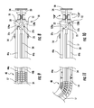
FIG. 14 is a partial cross-sectional view of a tool assembly of the end effector of the surgical instrument ofFIG. 1 when the actuation knob is in the neutral position; -
FIG. 15 is a partial cross-sectional view of the tool assembly ofFIG. 14 when the actuation knob is actuated; -
FIG. 16 is an exploded perspective view of the end effector of the surgical instrument ofFIG. 1 with parts separated; and -
FIG. 17 is a partial perspective view of the tool assembly of the end effector ofFIG. 1 . - Embodiments of the present disclosure will now be described in detail with reference to the drawings, in which like reference numerals designate identical or corresponding elements in each of the several views. As used herein, the term "distal," as is conventional, will refer to that portion of the instrument, apparatus, device or component thereof which is farther from the user while, the term "proximal," will refer to that portion of the instrument, apparatus, device or component thereof which is closer to the user. In the following description, well-known functions or constructions are not described in detail to avoid obscuring the present disclosure in unnecessary detail. Although the present disclosure is discussed in terms of a minimally invasive thoracic procedure, the presently disclosed instrument is usable in other minimally invasive procedures.
- With reference to
FIG. 1 , there is illustrated asurgical instrument 100 for dissecting and removing specimens, e.g., lymph nodes, during Video Assisted Thoracic Surgery (VATS) in accordance with an embodiment of the present disclosure. Lymph nodes are retrieved for specimen pathological analysis for, for example, cancer treatments. - With continued reference to
FIG. 1 ,surgical instrument 100 includes ahandle assembly 10, anelongate body 30 extending distally fromhandle assembly 10, anarticulation neck assembly 40 secured to a distal portion ofelongate body 30 and anend effector 60 operatively coupled to handleassembly 10 and extending distally fromarticulation neck assembly 40.End effector 60 includes a pair ofjaw members jaw members jaw members retractable cutting elements 76, 78 (FIG. 2 ) translatably disposed inrespective jaw members elements - With reference now to
FIGS. 2 and 3 , handleassembly 10 includes anapproximation handle 16, anarticulation knob 18 and/or anactuation knob 20. Approximation handle 16 may be squeezed to approximate the pair ofjaw members jaw members Articulation knob 18 may be rotated to provide articulation ofarticulation neck assembly 40 to enable, for example, a side-to-side, movement ofend effector 60.Actuation knob 20 may be moved distally to slide cuttingelements jaw members actuation knob 20 may be rotated to selectively positionend effector 60 to any rotational orientation about a longitudinal axis "X-X" (FIG. 1 ) of thesurgical instrument 100. - In particular, approximation handle 16 is secured to a
base member 12 ofhandle assembly 10. In addition, making reference toFIGS. 2 and 3 , approximation handle 16 is coupled to anapproximation rod 17 translatably disposed withinelongate body 30.Approximation rod 17 is operatively coupled withjaw members slidable collar 14 and is coupled withapproximation rod 17.Slidable collar 14 includes at least a pair of protrusions or camming pins (not shown) extending radially inward that engages a pair of respective opposing apertures or slots 13 (FIG. 1 ) defined inelongate body 30. In this manner, when approximation handle 16 is squeezed, the camming pins engage and slide withinrespective slots 13, andslidable collar 14 slides on an outer wall ofelongate body 30 alongslots 13. In this manner, translation ofslidable collar 14 causes translation ofapproximation rod 17. Such an arrangement facilitates secure translation ofapproximation rod 17 within a workingchannel 35 defined inelongate body 30. - With particular reference to
FIG. 3 ,approximation rod 17 extends throughelongate body 30 and at least partially intoend effector 60. In particular, a distal end ofapproximation rod 17 extends into asupport member 80 ofend effector 60.Support member 80 includes ananchor wall 81 extending radially inward and defining a bore configured and dimensioned to receive a distal end ofapproximation rod 17 therethrough.Approximation rod 17 may further include astopper 19.Stopper 19 is fixedly attached toapproximation rod 17 and translates withapproximation rod 17. In particular,stopper 19 is configured and adapted to secure a biasingmember 82 thereto. Under such configuration, biasingmember 82 is positioned betweenstopper 19 andanchor wall 81 ofsupport member 80. The bore defined inanchor wall 81 is dimensioned to only receiveapproximation rod 17 therethrough. In this manner, when approximation handle 16 is squeezed (FIGS. 4 and 6 ) inwardly towardelongate body 30,approximation rod 17 is translated distally (FIGS. 5 and 7 ), and thereby compressing biasing member 82 (FIG. 7 ) substantially betweenstopper 19 andanchor wall 81. Translatingapproximation rod 17 distally approximatesjaw members jaw members urges jaw members assembly 10 to lockjaw members U.S. Patent No. 8,336,754, filed on February 4, 2011 , andU.S. Patent Application Publication No. 2013/0012983, filed on July 9, 2012 , the entire contents of each of which are incorporated herein by reference, for a detailed discussion of the construction and operation of a locking mechanism. - With reference back to
FIGS. 2 and 3 , handleassembly 10 further includesarticulation knob 18 to enable, for example, side-to-side, movement ofend effector 60 atarticulation neck assembly 40. Other types of movement ofend effector 60, such as up-and-down or rotational, are also envisioned.Articulation knob 18 is rotatably secured tobase member 12. In particular,articulation knob 18 is rotatably coupled with arotatable hub 22 rotatably disposed withinelongate body 30 for concomitant rotation therewith.Rotatable hub 22 defines ahelical groove 25 on an outer surface of thereof.Rotatable hub 22 further includes a pair ofarms FIG. 3 ) each having arespective finger finger helical groove 25 ofrotatable hub 22. A distal end of eacharm respective articulation cable FIG. 3 ). Whenarticulation neck assembly 40 is in a neutral position, as shown inFIGS. 3 and9 ,articulation neck assembly 40 is aligned with a longitudinal axis "X-X" (FIG. 1 ) ofsurgical instrument 100, andfingers articulation knob 18 about longitudinal axis "X-X," in either direction "CW," "CCW" (FIG. 10 ),fingers helical groove 25 ofrotatable hub 22. In this manner, one ofarms respective articulation cable other arm other articulation cable articulation cables FIG. 11 ) enables articulation ofneck assembly 40, which in turn provides side-to-side movement ofend effector 60, as will be described in detail hereinbelow. - With continued reference to
FIG. 3 , handleassembly 10 includesactuation knob 20 operatively connected to anactuation rod 24.Actuation rod 24 extends through the entire length ofelongate body 30 and is operatively coupled with cuttingelements respective jaw member Actuation rod 24 is configured and dimensioned to extend througharticulation knob 18 andapproximation rod 17, as well asrotatable hub 22. In particular, each cuttingelement FIG. 14 ) ofrespective jaw member flexible shafts FIG. 15 ), respectively.Flexible shafts connector 99 and are coupled to actuation rod 24 (FIG. 3 ).Flexible shaft channels 90 inrespective jaw members flexible shaft - With reference to
FIG. 12 ,actuation rod 24 first extends througharticulation knob 18.Articulation knob 18 may define a passageway or a lumen. In particular, the lumen includes ananchor wall 55 similar to anchorwall 81 ofsupport member 80.Actuation rod 24 may include astopper 57. Similar tostopper 19 ofapproximation rod 17,stopper 57 is fixedly attached toactuation rod 24 and translates withactuation rod 24. A biasingmember 59 is securely interposed betweenanchor wall 55 andstopper 57. Whenactuation knob 20 is moved distally (FIG. 13 ),actuation rod 24 is translated distally andstopper 57compresses biasing member 59 againstanchor wall 55. As such,actuation rod 24 translates against the bias of biasingmember 59.Actuation rod 24 extends throughrotatable hub 22 and throughapproximation rod 17, as shown inFIG. 2 .Actuation rod 24 is coupled withflexible shafts actuation rod 24 causes concomitant translation offlexible shafts moves cutting elements respective jaw members - With reference to
FIGS. 12-15 , whenactuation knob 20 is in a neutral position (FIGS. 12 and 14 ), cuttingelements respective jaw member actuation knob 20 is moved distally (FIG. 13 ) cuttingelements channels 90 ofrespective jaw members FIGS. 13 and 15 ). Release ofactuation knob 20 allows biasingmember 59 to expand and urgesstopper 57 proximally which movesactuation rod 24 proximally and cuttingelements respective channel 90 ofjaw member actuation knob 20 may include a locking mechanism (not shown) that locks the desired retraction positions of cuttingelements respective channels 90. - With reference back to
FIGS. 2 and 3 ,elongate body 30 defines a workingchannel 35 dimensioned and configured to accommodate thereinrotatable hub 22,actuation rod 24,articulation cable approximation rod 17, as described hereinabove. Whileelongate body 30, as shown, is substantially straight, it is also contemplated thatelongate body 30 may be relatively flexible to facilitate insertion into a patient's body. A distal portion ofelongate body 30 is coupled witharticulation neck assembly 40.Articulation neck assembly 40 includes a plurality of articulation links 42. Each articulation link 42 is pivotally associated with adjacent articulation links 42. Each articulation link 42 may have a semi-spherical shape, wherebyadjacent links 42 defines agap 43 therebetween.Such gap 43 enables pivotal rotation of eachlink 42. Other shapes for articulation links, such as spherical or crescent, are also contemplated. In addition, eachlink 42 may define a bore on each opposing side oflink 42 with respect to pivot axis 45 (FIG. 3 ). Each bore is configured and dimensioned to receive therethroughrespective articulation cable distal-most link 42d is securely connected toarticulation cables articulation cables neck assembly 40, thereby enabling, for example, a side-to-side, movement of end effector 60 (FIG. 11 ). - With reference now to
FIGS. 1 and16 ,end effector 60 is operatively coupled to handleassembly 10 and extends distally fromarticulation neck assembly 40.End effector 60 includes atool assembly 70 and asupport member 80.Tool assembly 70 includes a pair ofjaw members jaw members jaw members jaw member pivot bore 73a, 73b, wherebyjaw members pivot pin 62 inpivot bore 73a, 73b. In addition, eachjaw member camming slot camming slot -
Support member 80 securesend effector 60 toarticulation neck assembly 40.Support member 80 may define a lumen therethrough 87 and alongitudinal slot 85 on anouter wall 81 thereof.Longitudinal slot 85 is in communication withlumen 87. A distal end ofapproximation rod 17 is connected to aproximal end 99a of aconnector 99.Connector 99 defines atransverse bore 97 configured and dimensioned to receivecamming pin 64 therein.Camming pin 64 is configured and dimensioned to slidably engagecamming slots jaw members longitudinal slot 85 ofsupport member 80. Under such configuration, ascamming pin 64 slidably translates alonglongitudinal slot 85 through translation ofapproximation rod 17 andconnector 99,camming pin 64 slidably engagescamming slots respective jaw members connector 99 through translation ofapproximation rod 17 enables opening and closing ofjaw members - With particular reference now to
FIGS. 16 and17 , eachjaw member channel 90 configured and dimensioned to slidably receive cuttingelements element flexible shaft Flexible shafts channel 90 defined in eachjaw member actuation rod 24 that is operatively coupled toactuation knob 20. Under such configuration, translation of articulation knob 20 (FIGS. 12 and 13 ) causes translation of cuttingelements respective channel 90, and thereby enabling movement of cuttingelements respective channel 90. Additionally, rotation ofactuation knob 20 causes rotation ofend effector 60 about longitudinal axis "X-X" with respect toarticulation neck assembly 40. - In addition, cutting
elements FIG. 1 ) and a generator 500 (FIG. 1 ).Switch 510 is configured to selectively provide electrical energy to the electrodes to cut tissue disposed therebetween. For example, rocker switches, toggle switches, flip switches, dials, etc. are types of switches that can be commonly employed to accomplish this purpose. These switches can be placed anywhere on the instrument or may be configured as a remote switch, e.g., hand switch or a foot switch.Generator 500 delivers energy to tissue in a pulse-like waveform. RF pulsing may be used to more effectively cut tissue. For example, an initial pulse from the cutting element through the tissue (or the tissue contacting surfaces through the tissue) may be delivered to provide feedback to the smart sensor for selection of the ideal number of subsequent pulses and subsequent pulse intensity to effectively and consistently cut the amount or type of tissue. - The geometry of the electrodes may be configured such that the surface area ratios between the electrical poles focus electrical energy at tissue. An insulator is disposed
adjacent channel 90. The insulator or insulative material may be of any suitable composition such as, for example, glass, polymeric, and ceramic materials. Moreover, the geometrical configurations of the electrodes and insulators may be designed such that they act like electrical sinks or insulators to influence the heat effect within and around tissue during the cutting processes. - With particular reference to
FIG. 16 , cuttingelements element -
Cutting elements actuation knob 20 is actuated (moved distally). Alternatively, a pair of cutting elements may be configured to be in general transverse registration when actuated. For example, each jaw may include a channel that is U-shaped, and the pair of cutting elements may be slidably disposed adjacent the respective lateral sides prior to actuation. Upon actuation, the cutting elements extend out of the jaw in general transverse registration. It is also contemplated that the cutting element may be rotatably mounted in a jaw member such that a cutting element disposed within the jaw member may be rotated to extend out of the jaw member when actuated. For example, the cutting elements may rotate about the ends of the jaw members, respectively. It is also envisioned that both the jaw members and the cutting elements may be curved, and the cutting elements may extend out along the curvature of the jaw members when actuated. During the cutting phase, highly concentrated electrical energy may travel from the cutting element through tissue to cut tissue. The number of pulses required to effectively cut tissue and the intensity of the cutting energy may be determined by measuring tissue impedance. A smart sensor (not shown) or feedback loop may be employed for this purpose. - It is also envisioned that a mechanical or electrical lockout mechanism that prevents cutting
elements jaw members elements respective channels 90 ofrespective jaw member - In use, the surgeon creates an incision through an intercostal space, such as the area between the ribs of a patient into a cavity, such as the thoracic cavity. It will be appreciated that the surgeon may enter any body cavity through any known procedure. A portal, known to those skilled in the art, may optionally be inserted into the incision to prevent the incision from closing. Reference may be made to
U.S. Patent Application Publication Nos. 2012/0245427, filed on February 10, 2012 , and2012/0283520, filed on April 5, 2012 , the entire contents of each of which are incorporated herein by reference, for a detailed discussion of the construction and operation of a portal.Surgical instrument 10 withjaw members surgical instrument 10 is positioned in the thoracic cavity, the surgeon may then adjustmovable handle assembly 10 to orientjaw members neck assembly 40 and rotation ofend effector 60,jaw members jaw members actuation knob 20 may be moved distally to actuate cuttingelements U.S. Patent Application Publication No. 2008/0086154, filed on October 6, 2006 , the entire contents of which are incorporated herein by reference, for a detailed discussion of the construction and operation of an actuation mechanism. - Upon vertical registration of cutting
elements switch 510 to effect cutting of the specimen, e.g., lymph node. Upon cutting of the specimen, cuttingelements respective channel 90 injaw member jaw members jaw members surgical instrument 100 may be removed from the patient. Alternatively, the specimen may be transferred to a storage vessel prior to extraction from the patient. Thesurgical instrument 100 is then removed from the body of the patient and the specimen is removed from the cavity and placed in, for example, a proper receptacle for further examination. The obtained specimen, e.g., lymph node, may be delivered to a technician for further processing. - Although the illustrative embodiments of the present disclosure have been described herein with reference to the accompanying drawings, the above description, disclosure, and figures should not be construed as limiting, but merely as exemplifications of particular embodiments. Persons skilled in the art will understand that the devices and methods specifically described herein and illustrated in the accompanying drawings are non-limiting exemplary embodiments. For example, one skilled in the art may contemplate using a plurality of different cutting mechanisms of different shapes and sizes to cut, for example, a portion of tissue. Any combination of the above embodiments is also envisioned and is within the scope of the claimed invention. Moreover, the
end effector 60 may comprise any suitable shape and material. Solely by way of example, theend effector 60 may comprise stainless steel or a biocompatible plastic. Theend effector 60 may be substantially cylindrically-shaped. It is to be understood, therefore, that the disclosure is not limited to those precise embodiments, and that various other changes and modifications may be effected therein by one skilled in the art without departing from the scope or spirit of the disclosure. - The invention may be described by reference to the following numbered paragraphs:-
- 1. A surgical instrument, comprising:
- a handle assembly including an actuation knob;
- an elongate body extending distally from the handle assembly and defining a longitudinal axis;
- a tool assembly operatively coupled to the handle assembly and extending from a distal end of the elongate body, the tool assembly including:
- first and second jaw members each including an electrically conductive cutting element, the cutting elements operatively coupled to the actuation knob, wherein the cutting elements are movable between a first position in which the cutting elements are disposed within the respective jaw members and a second position in which the cutting elements extend out of the respective jaw members and are in general vertical registration with each other such that electrical energy can be transferred from the first jaw member to the second jaw member; and
- an electrical energy source for providing electrical energy to at least one of the cutting elements.
- 2. The surgical instrument according to paragraph 1, wherein the first and second jaw members are movable between a spaced apart position and an approximated position in which the jaw members are adjacent to each other to clamp tissue therebetween, wherein the first and second jaw members each define a channel configured to slidably receive the respective cutting element.
- 3. The surgical instrument according to paragraph 1, further comprising an actuation rod interconnecting the actuation knob and the cutting elements, wherein translation of the actuation knob causes transition of the cutting elements between the first and second positions, and rotation of the actuation knob causes rotation of the jaw members about the longitudinal axis.
- 4. The surgical instrument according to paragraph 3, further comprising an approximation rod extending through the elongate body and operatively coupled to the first and second jaw members, wherein translation of approximation rod moves the first and second jaw members between the spaced apart and approximated positions.
- 5. The surgical instrument according to paragraph 4, wherein the approximation rod and the actuation rod are concentrically arranged.
- 6. The surgical instrument according to paragraph 5, wherein the handle assembly includes a slidable collar configured and adapted to slide over the elongate body, the slidable collar being operatively coupled with the approximation rod for a concomitant translation therewith.
- 7. The surgical instrument according to paragraph 1, further comprising an articulation assembly including a plurality of articulation links pivotably coupled to each other and at least a pair of articulation cables interconnecting the plurality of articulation links, wherein the at least pair of articulation cables is operatively coupled to the handle assembly.
- 8. The surgical instrument according to paragraph 7, wherein the handle assembly further includes a rotatable hub defining a helical groove on an outer wall thereof, wherein proximal ends of the at least pair of articulation cables are configured and adapted to slidably engage the helical groove, whereby rotation of the rotatable hub translates the at least pair of articulation cables in opposite directions.
- 9. The surgical instrument according to paragraph 1, wherein the tool assembly is rotatable about the longitudinal axis.
- 10. The surgical instrument according to paragraph 1, wherein the cutting elements are substantially dull, the cutting elements being configured and adapted to cut tissue through application of electrical energy thereto.
- 11. The surgical instrument according to paragraph 1, the first and second jaw members each include a tissue contacting surface having teeth configured and adapted to grasp tissue.
- 12. A method of removing tissue, the method comprising:
- providing a surgical instrument including:
- an elongate body defining a longitudinal axis; and
- a tool assembly secured to a distal end of the elongate body, the tool assembly including first and second jaw members each including an electrically conductive cutting element slidably disposed therein, wherein the cutting elements are movable between a first position in which the cutting elements are disposed within the respective jaw members and a second position in which the cutting elements are disposed in general vertical registration to each other such that electrical energy can be transferred through tissue positioned between the cutting elements to cut tissue;
- introducing the surgical instrument into a patient;
- advancing the tool assembly toward a target tissue within the patient;
- placing tissue between the first and second jaw members;
- positioning the cutting elements in general vertical registration to each other;
- cutting tissue positioned between the cutting elements; and
- extracting tissue from the target surgical site.
- providing a surgical instrument including:
- 13. The method according to
paragraph 12, wherein cutting tissue positioned between the cutting elements includes supplying electrical energy to the cutting elements. - 14. The method according to
paragraph 12, wherein the surgical instrument further includes an articulation mechanism for articulating the tool assembly. - 15. The method according to
paragraph 12, wherein the surgical instrument further includes an actuation knob operatively coupled to the cutting elements, wherein translation of the actuation knob causes transition of the cutting elements between the first and second positions, and rotation of the actuation knob causes rotation of the first and second jaw members about the longitudinal axis. - 16. The method according to
paragraph 12, wherein the first and second jaw members are movable between a spaced apart position and an approximated position in which the jaw members are adjacent to each other to clamp tissue therebetween, wherein the first and second jaw members each define a channel configured and dimensioned to slidably receive the respective cutting element therethrough. - 17. The method according to
paragraph 12, wherein the surgical instrument further includes an approximation rod extending through the elongate body and operatively coupled to the first and second jaw members, wherein translation of approximation rod moves the first and second jaw members between the spaced apart and approximated positions. - 18. The method according to
paragraph 17, wherein the surgical instrument further includes a slidable collar configured and adapted to slide over the elongate body, the slidable collar being operatively coupled with the approximation rod for a concomitant translation therewith. - 19. The method according to
paragraph 12, wherein the cutting elements are substantially dull, the cutting elements being configured and adapted to cut tissue through application of electrical energy thereto. - 20. The method according to
paragraph 12, further comprising rotating the tool assembly about the longitudinal axis.
Claims (11)
- A surgical instrument, comprising:a handle assembly including an actuation knob;an elongate body extending distally from the handle assembly and defining a longitudinal axis;a tool assembly operatively coupled to the handle assembly and extending from a distal end of the elongate body, the tool assembly including:first and second jaw members each including an electrically conductive cutting element, the cutting elements operatively coupled to the actuation knob, wherein the cutting elements are movable between a first position in which the cutting elements are disposed within the respective jaw members and a second position in which the cutting elements extend out of the respective jaw members and are in general vertical registration with each other such that electrical energy can be transferred from the first jaw member to the second jaw member; andan electrical energy source for providing electrical energy to at least one of the cutting elements.
- The surgical instrument according to claim 1, wherein the first and second jaw members are movable between a spaced apart position and an approximated position in which the jaw members are adjacent to each other to clamp tissue therebetween, wherein the first and second jaw members each define a channel configured to slidably receive the respective cutting element.
- The surgical instrument according to claim 1 or claim 2, further comprising an actuation rod interconnecting the actuation knob and the cutting elements, wherein translation of the actuation knob causes transition of the cutting elements between the first and second positions, and rotation of the actuation knob causes rotation of the jaw members about the longitudinal axis.
- The surgical instrument according to claim 3, further comprising an approximation rod extending through the elongate body and operatively coupled to the first and second jaw members, wherein translation of approximation rod moves the first and second jaw members between the spaced apart and approximated positions.
- The surgical instrument according to claim 4, wherein the approximation rod and the actuation rod are concentrically arranged.
- The surgical instrument according to any preceding claim, wherein the handle assembly includes a slidable collar configured and adapted to slide over the elongate body, the slidable collar being operatively coupled with the approximation rod for a concomitant translation therewith.
- The surgical instrument according to any preceding claim, further comprising an articulation assembly including a plurality of articulation links pivotably coupled to each other and at least a pair of articulation cables interconnecting the plurality of articulation links, wherein the at least pair of articulation cables is operatively coupled to the handle assembly.
- The surgical instrument according to claim 7, wherein the handle assembly further includes a rotatable hub defining a helical groove on an outer wall thereof, wherein proximal ends of the at least pair of articulation cables are configured and adapted to slidably engage the helical groove, whereby rotation of the rotatable hub translates the at least pair of articulation cables in opposite directions.
- The surgical instrument according to any preceding claim, wherein the tool assembly is rotatable about the longitudinal axis.
- The surgical instrument according to any preceding claim, wherein the cutting elements are substantially dull, the cutting elements being configured and adapted to cut tissue through application of electrical energy thereto.
- The surgical instrument according to any preceding claim, the first and second jaw members each include a tissue contacting surface having teeth configured and adapted to grasp tissue.
Applications Claiming Priority (2)
| Application Number | Priority Date | Filing Date | Title |
|---|---|---|---|
| US201361779198P | 2013-03-13 | 2013-03-13 | |
| US14/197,382 US9427251B2 (en) | 2013-03-13 | 2014-03-05 | Saber tooth harvester |
Publications (2)
| Publication Number | Publication Date |
|---|---|
| EP2777588A2 true EP2777588A2 (en) | 2014-09-17 |
| EP2777588A3 EP2777588A3 (en) | 2014-11-05 |
Family
ID=50342157
Family Applications (1)
| Application Number | Title | Priority Date | Filing Date |
|---|---|---|---|
| EP14159050.5A Withdrawn EP2777588A3 (en) | 2013-03-13 | 2014-03-12 | Saber tooth harvester |
Country Status (6)
| Country | Link |
|---|---|
| US (2) | US9427251B2 (en) |
| EP (1) | EP2777588A3 (en) |
| JP (1) | JP2014176680A (en) |
| CN (1) | CN104042255B (en) |
| AU (1) | AU2014201265A1 (en) |
| CA (1) | CA2845450A1 (en) |
Families Citing this family (24)
| Publication number | Priority date | Publication date | Assignee | Title |
|---|---|---|---|---|
| US9428254B1 (en) | 2010-09-24 | 2016-08-30 | Katalyst Surgical, Llc | Microsurgical handle and instrument |
| US8821444B2 (en) | 2011-10-03 | 2014-09-02 | Katalyst Surgical, Llc | Multi-utility surgical instrument |
| US9138346B2 (en) | 2012-01-26 | 2015-09-22 | Katalyst Surgical, Llc | Surgical instrument sleeve |
| US9629645B2 (en) | 2012-10-30 | 2017-04-25 | Katalyst Surgical, Llc | Atraumatic microsurgical forceps |
| US9226762B2 (en) | 2012-11-07 | 2016-01-05 | Katalyst Surgical, Llc | Atraumatic microsurgical forceps |
| US9427251B2 (en) * | 2013-03-13 | 2016-08-30 | Covidien Lp | Saber tooth harvester |
| US20150088193A1 (en) * | 2013-09-24 | 2015-03-26 | Katalyst Surgical, Llc | Membrane removing forceps |
| KR20160088393A (en) * | 2013-11-19 | 2016-07-25 | 에디컨인코포레이티드 | Thoracoscopic methods for treatment of bronchial disease |
| US10022267B2 (en) | 2014-04-21 | 2018-07-17 | Katalyst Surgical, Llc | Method of manufacturing a microsurgical instrument tip |
| US9775943B2 (en) | 2014-10-10 | 2017-10-03 | Katalyst Surgical, Llc | Cannula ingress system |
| US20160367311A1 (en) * | 2015-06-16 | 2016-12-22 | Lawrence J. Gerrans | Instrumentation with Embedded Imaging Systems |
| EP3471673A1 (en) | 2016-06-16 | 2019-04-24 | Katalyst Surgical, LLC | Reusable instrument handle with single- use tip |
| US11304747B2 (en) * | 2016-11-16 | 2022-04-19 | Boston Scientific Scimed, Inc. | Rotatable snares and related methods |
| CN108078609B (en) * | 2016-11-21 | 2020-09-11 | 张小彤 | Clamping device for cecum surgery |
| US10695043B2 (en) | 2017-02-21 | 2020-06-30 | Katalyst Surgical, Llc | Surgical instrument subcomponent integration by additive manufacturing |
| CN106826943B (en) * | 2017-03-30 | 2018-08-21 | 上海海洋大学 | A kind of sclerous tissues' cutter for primitive cell culture |
| US20210093369A1 (en) * | 2017-12-19 | 2021-04-01 | Intuitive Surgical Operations, Inc. | Simultaneous electrosurgical sealing and cutting |
| US10849640B2 (en) | 2018-05-23 | 2020-12-01 | Katalyst Surgical, Llc | Membrane aggregating forceps |
| CN108618831B (en) * | 2018-05-28 | 2020-08-04 | 刘方舟 | Cervical lymph node cleaning retractor |
| EP3578118B1 (en) * | 2018-06-05 | 2022-08-31 | Erbe Elektromedizin GmbH | Surgical instrument |
| WO2020249089A1 (en) * | 2019-06-14 | 2020-12-17 | 袁美欣 | Sampling device and sampling system |
| CN110432978A (en) * | 2019-08-12 | 2019-11-12 | 南京脑科医院 | A kind of bipolar electrocoagulator with micro- scissors |
| US20230009937A1 (en) * | 2021-07-07 | 2023-01-12 | Covidien Lp | Stapling end effectors for endoscopic procedures |
| CN115836885B (en) * | 2023-02-28 | 2023-05-05 | 吉林大学 | Tumor biopsy forceps |
Citations (5)
| Publication number | Priority date | Publication date | Assignee | Title |
|---|---|---|---|---|
| US20080086154A1 (en) | 2006-10-06 | 2008-04-10 | Taylor Eric J | Coil fastener applier with flexible shaft |
| US20120245427A1 (en) | 2011-03-23 | 2012-09-27 | Tyco Healthcare Group Lp | Surgical retractor including rotatable knobs |
| US20120283520A1 (en) | 2011-05-02 | 2012-11-08 | Tyco Healthcare Group Lp | Surgical retractor including polygonal rolling structure |
| US8336754B2 (en) | 2011-02-04 | 2012-12-25 | Covidien Lp | Locking articulation mechanism for surgical stapler |
| US20130012983A1 (en) | 2011-07-08 | 2013-01-10 | Tyco Healthcare Group Lp | Surgical Instrument with Flexible Shaft |
Family Cites Families (20)
| Publication number | Priority date | Publication date | Assignee | Title |
|---|---|---|---|---|
| US5645075A (en) | 1992-02-18 | 1997-07-08 | Symbiosis Corporation | Jaw assembly for an endoscopic instrument |
| US5636639A (en) | 1992-02-18 | 1997-06-10 | Symbiosis Corporation | Endoscopic multiple sample bioptome with enhanced biting action |
| US5643294A (en) * | 1993-03-01 | 1997-07-01 | United States Surgical Corporation | Surgical apparatus having an increased range of operability |
| US5893873A (en) * | 1995-10-23 | 1999-04-13 | Johns Hopkins University | Surgical instrument having a handle with a removable, rotatable tip |
| US5827281A (en) * | 1996-01-05 | 1998-10-27 | Levin; John M. | Insulated surgical scissors |
| US5683388A (en) | 1996-01-11 | 1997-11-04 | Symbiosis Corporation | Endoscopic bipolar multiple sample bioptome |
| US5908420A (en) * | 1997-10-03 | 1999-06-01 | Everest Medical Corporation | Surgical scissors with bipolar distal electrodes |
| US6514252B2 (en) | 1998-05-01 | 2003-02-04 | Perfect Surgical Techniques, Inc. | Bipolar surgical instruments having focused electrical fields |
| US6632182B1 (en) | 1998-10-23 | 2003-10-14 | The Trustees Of Columbia University In The City Of New York | Multiple bit, multiple specimen endoscopic biopsy forceps |
| US20040162551A1 (en) | 2000-12-15 | 2004-08-19 | Brown Tony R. | Method and device for creating transmural lesions |
| US20020111624A1 (en) * | 2001-01-26 | 2002-08-15 | Witt David A. | Coagulating electrosurgical instrument with tissue dam |
| US7276068B2 (en) * | 2002-10-04 | 2007-10-02 | Sherwood Services Ag | Vessel sealing instrument with electrical cutting mechanism |
| EP1863388A1 (en) * | 2005-03-03 | 2007-12-12 | Granit Medical Innovations, LLC | Needle biopsy forceps with integral sample ejector |
| US7766910B2 (en) * | 2006-01-24 | 2010-08-03 | Tyco Healthcare Group Lp | Vessel sealer and divider for large tissue structures |
| JP2008264253A (en) | 2007-04-20 | 2008-11-06 | Olympus Medical Systems Corp | Medical treatment tool and endoscope treatment system |
| US20110040308A1 (en) * | 2008-06-13 | 2011-02-17 | Ramiro Cabrera | Endoscopic Stitching Devices |
| US20110238057A1 (en) | 2010-02-16 | 2011-09-29 | Angiodynamics, Inc. | Dual Bracketed Energy Delivery Probe and Method of Use |
| US8641712B2 (en) * | 2010-07-28 | 2014-02-04 | Covidien Lp | Local optimization of electrode current densities |
| US10092349B2 (en) * | 2011-05-04 | 2018-10-09 | The University Of Akron | Variable-frequency stimulator for electrosurgery |
| US9427251B2 (en) * | 2013-03-13 | 2016-08-30 | Covidien Lp | Saber tooth harvester |
-
2014
- 2014-03-05 US US14/197,382 patent/US9427251B2/en not_active Expired - Fee Related
- 2014-03-07 AU AU2014201265A patent/AU2014201265A1/en not_active Abandoned
- 2014-03-11 CA CA2845450A patent/CA2845450A1/en not_active Abandoned
- 2014-03-12 EP EP14159050.5A patent/EP2777588A3/en not_active Withdrawn
- 2014-03-13 CN CN201410093102.2A patent/CN104042255B/en active Active
- 2014-03-13 JP JP2014049738A patent/JP2014176680A/en active Pending
-
2016
- 2016-08-01 US US15/224,715 patent/US9775670B2/en active Active
Patent Citations (5)
| Publication number | Priority date | Publication date | Assignee | Title |
|---|---|---|---|---|
| US20080086154A1 (en) | 2006-10-06 | 2008-04-10 | Taylor Eric J | Coil fastener applier with flexible shaft |
| US8336754B2 (en) | 2011-02-04 | 2012-12-25 | Covidien Lp | Locking articulation mechanism for surgical stapler |
| US20120245427A1 (en) | 2011-03-23 | 2012-09-27 | Tyco Healthcare Group Lp | Surgical retractor including rotatable knobs |
| US20120283520A1 (en) | 2011-05-02 | 2012-11-08 | Tyco Healthcare Group Lp | Surgical retractor including polygonal rolling structure |
| US20130012983A1 (en) | 2011-07-08 | 2013-01-10 | Tyco Healthcare Group Lp | Surgical Instrument with Flexible Shaft |
Also Published As
| Publication number | Publication date |
|---|---|
| CN104042255B (en) | 2019-03-12 |
| JP2014176680A (en) | 2014-09-25 |
| US20160338765A1 (en) | 2016-11-24 |
| US20140277049A1 (en) | 2014-09-18 |
| AU2014201265A1 (en) | 2014-10-02 |
| US9775670B2 (en) | 2017-10-03 |
| CN104042255A (en) | 2014-09-17 |
| EP2777588A3 (en) | 2014-11-05 |
| CA2845450A1 (en) | 2014-09-13 |
| US9427251B2 (en) | 2016-08-30 |
Similar Documents
| Publication | Publication Date | Title |
|---|---|---|
| US9775670B2 (en) | Saber tooth harvester | |
| US6017358A (en) | Surgical instrument with multiple rotatably mounted offset end effectors | |
| EP1813303B1 (en) | Medical instrument including an end effector having a medical treatment electrode | |
| US5819738A (en) | Jaw assembly having progressively larger teeth and endoscopic biopsy forceps instrument incorporating same | |
| EP1261286B1 (en) | Surgical instrument | |
| CN103096827B (en) | There is independent closure member and the electrosurgical unit of cutting element | |
| US8968359B2 (en) | Surgical forceps | |
| US5366476A (en) | Handle for laparoscopic instrument | |
| US5797939A (en) | Endoscopic scissors with longitudinal operating channel | |
| US6080180A (en) | Surgical instrument with rotatably mounted offset end effector and method of using the same | |
| US11369401B2 (en) | Reverse seam ripper dissector | |
| JP2008528109A (en) | Biopsy forceps | |
| WO1999017661A1 (en) | Subcutaneous endoscopic dissector | |
| KR102013539B1 (en) | Minimally invasive surgical assembly and methods | |
| WO2008070718A1 (en) | Monopolar resection device and method of use | |
| JP2001512703A (en) | Surgical instrument with arcuately movable offset end effector and method of using same | |
| CN108463182B (en) | Clamp jaw mechanism | |
| US20130237877A1 (en) | Tissue dissection and removal device | |
| US9549661B2 (en) | Medical device actuation systems and related methods of use | |
| US20180110560A1 (en) | Minimally invasive surgical devices | |
| KR20200139430A (en) | Treatment device for endoscope | |
| JP7459311B2 (en) | treatment equipment | |
| WO1995014435A1 (en) | Endocospic surgical instrument |
Legal Events
| Date | Code | Title | Description |
|---|---|---|---|
| 17P | Request for examination filed |
Effective date: 20140312 |
|
| AK | Designated contracting states |
Kind code of ref document: A2 Designated state(s): AL AT BE BG CH CY CZ DE DK EE ES FI FR GB GR HR HU IE IS IT LI LT LU LV MC MK MT NL NO PL PT RO RS SE SI SK SM TR |
|
| AX | Request for extension of the european patent |
Extension state: BA ME |
|
| PUAI | Public reference made under article 153(3) epc to a published international application that has entered the european phase |
Free format text: ORIGINAL CODE: 0009012 |
|
| PUAL | Search report despatched |
Free format text: ORIGINAL CODE: 0009013 |
|
| AK | Designated contracting states |
Kind code of ref document: A3 Designated state(s): AL AT BE BG CH CY CZ DE DK EE ES FI FR GB GR HR HU IE IS IT LI LT LU LV MC MK MT NL NO PL PT RO RS SE SI SK SM TR |
|
| AX | Request for extension of the european patent |
Extension state: BA ME |
|
| RIC1 | Information provided on ipc code assigned before grant |
Ipc: A61B 18/14 20060101AFI20141002BHEP |
|
| R17P | Request for examination filed (corrected) |
Effective date: 20141211 |
|
| RBV | Designated contracting states (corrected) |
Designated state(s): AL AT BE BG CH CY CZ DE DK EE ES FI FR GB GR HR HU IE IS IT LI LT LU LV MC MK MT NL NO PL PT RO RS SE SI SK SM TR |
|
| STAA | Information on the status of an ep patent application or granted ep patent |
Free format text: STATUS: THE APPLICATION HAS BEEN WITHDRAWN |
|
| 18W | Application withdrawn |
Effective date: 20161011 |