EP2777085B1 - One-piece housing with plugs for prismatic cell assembly - Google Patents
One-piece housing with plugs for prismatic cell assembly Download PDFInfo
- Publication number
- EP2777085B1 EP2777085B1 EP12799672.6A EP12799672A EP2777085B1 EP 2777085 B1 EP2777085 B1 EP 2777085B1 EP 12799672 A EP12799672 A EP 12799672A EP 2777085 B1 EP2777085 B1 EP 2777085B1
- Authority
- EP
- European Patent Office
- Prior art keywords
- casing
- cells
- housing system
- plug
- plugs
- Prior art date
- Legal status (The legal status is an assumption and is not a legal conclusion. Google has not performed a legal analysis and makes no representation as to the accuracy of the status listed.)
- Active
Links
Images


Classifications
-
- H—ELECTRICITY
- H01—ELECTRIC ELEMENTS
- H01M—PROCESSES OR MEANS, e.g. BATTERIES, FOR THE DIRECT CONVERSION OF CHEMICAL ENERGY INTO ELECTRICAL ENERGY
- H01M10/00—Secondary cells; Manufacture thereof
- H01M10/04—Construction or manufacture in general
- H01M10/0481—Compression means other than compression means for stacks of electrodes and separators
-
- H—ELECTRICITY
- H01—ELECTRIC ELEMENTS
- H01M—PROCESSES OR MEANS, e.g. BATTERIES, FOR THE DIRECT CONVERSION OF CHEMICAL ENERGY INTO ELECTRICAL ENERGY
- H01M10/00—Secondary cells; Manufacture thereof
- H01M10/60—Heating or cooling; Temperature control
- H01M10/64—Heating or cooling; Temperature control characterised by the shape of the cells
- H01M10/647—Prismatic or flat cells, e.g. pouch cells
-
- H—ELECTRICITY
- H01—ELECTRIC ELEMENTS
- H01M—PROCESSES OR MEANS, e.g. BATTERIES, FOR THE DIRECT CONVERSION OF CHEMICAL ENERGY INTO ELECTRICAL ENERGY
- H01M10/00—Secondary cells; Manufacture thereof
- H01M10/60—Heating or cooling; Temperature control
- H01M10/62—Heating or cooling; Temperature control specially adapted for specific applications
- H01M10/625—Vehicles
-
- H—ELECTRICITY
- H01—ELECTRIC ELEMENTS
- H01M—PROCESSES OR MEANS, e.g. BATTERIES, FOR THE DIRECT CONVERSION OF CHEMICAL ENERGY INTO ELECTRICAL ENERGY
- H01M10/00—Secondary cells; Manufacture thereof
- H01M10/60—Heating or cooling; Temperature control
- H01M10/65—Means for temperature control structurally associated with the cells
- H01M10/655—Solid structures for heat exchange or heat conduction
- H01M10/6554—Rods or plates
-
- H—ELECTRICITY
- H01—ELECTRIC ELEMENTS
- H01M—PROCESSES OR MEANS, e.g. BATTERIES, FOR THE DIRECT CONVERSION OF CHEMICAL ENERGY INTO ELECTRICAL ENERGY
- H01M50/00—Constructional details or processes of manufacture of the non-active parts of electrochemical cells other than fuel cells, e.g. hybrid cells
- H01M50/20—Mountings; Secondary casings or frames; Racks, modules or packs; Suspension devices; Shock absorbers; Transport or carrying devices; Holders
- H01M50/204—Racks, modules or packs for multiple batteries or multiple cells
- H01M50/207—Racks, modules or packs for multiple batteries or multiple cells characterised by their shape
- H01M50/209—Racks, modules or packs for multiple batteries or multiple cells characterised by their shape adapted for prismatic or rectangular cells
-
- H—ELECTRICITY
- H01—ELECTRIC ELEMENTS
- H01M—PROCESSES OR MEANS, e.g. BATTERIES, FOR THE DIRECT CONVERSION OF CHEMICAL ENERGY INTO ELECTRICAL ENERGY
- H01M50/00—Constructional details or processes of manufacture of the non-active parts of electrochemical cells other than fuel cells, e.g. hybrid cells
- H01M50/20—Mountings; Secondary casings or frames; Racks, modules or packs; Suspension devices; Shock absorbers; Transport or carrying devices; Holders
- H01M50/218—Mountings; Secondary casings or frames; Racks, modules or packs; Suspension devices; Shock absorbers; Transport or carrying devices; Holders characterised by the material
- H01M50/22—Mountings; Secondary casings or frames; Racks, modules or packs; Suspension devices; Shock absorbers; Transport or carrying devices; Holders characterised by the material of the casings or racks
- H01M50/227—Organic material
-
- H—ELECTRICITY
- H01—ELECTRIC ELEMENTS
- H01M—PROCESSES OR MEANS, e.g. BATTERIES, FOR THE DIRECT CONVERSION OF CHEMICAL ENERGY INTO ELECTRICAL ENERGY
- H01M50/00—Constructional details or processes of manufacture of the non-active parts of electrochemical cells other than fuel cells, e.g. hybrid cells
- H01M50/20—Mountings; Secondary casings or frames; Racks, modules or packs; Suspension devices; Shock absorbers; Transport or carrying devices; Holders
- H01M50/233—Mountings; Secondary casings or frames; Racks, modules or packs; Suspension devices; Shock absorbers; Transport or carrying devices; Holders characterised by physical properties of casings or racks, e.g. dimensions
-
- H—ELECTRICITY
- H01—ELECTRIC ELEMENTS
- H01M—PROCESSES OR MEANS, e.g. BATTERIES, FOR THE DIRECT CONVERSION OF CHEMICAL ENERGY INTO ELECTRICAL ENERGY
- H01M50/00—Constructional details or processes of manufacture of the non-active parts of electrochemical cells other than fuel cells, e.g. hybrid cells
- H01M50/20—Mountings; Secondary casings or frames; Racks, modules or packs; Suspension devices; Shock absorbers; Transport or carrying devices; Holders
- H01M50/289—Mountings; Secondary casings or frames; Racks, modules or packs; Suspension devices; Shock absorbers; Transport or carrying devices; Holders characterised by spacing elements or positioning means within frames, racks or packs
- H01M50/291—Mountings; Secondary casings or frames; Racks, modules or packs; Suspension devices; Shock absorbers; Transport or carrying devices; Holders characterised by spacing elements or positioning means within frames, racks or packs characterised by their shape
-
- H—ELECTRICITY
- H01—ELECTRIC ELEMENTS
- H01M—PROCESSES OR MEANS, e.g. BATTERIES, FOR THE DIRECT CONVERSION OF CHEMICAL ENERGY INTO ELECTRICAL ENERGY
- H01M10/00—Secondary cells; Manufacture thereof
- H01M10/05—Accumulators with non-aqueous electrolyte
- H01M10/058—Construction or manufacture
- H01M10/0585—Construction or manufacture of accumulators having only flat construction elements, i.e. flat positive electrodes, flat negative electrodes and flat separators
-
- Y—GENERAL TAGGING OF NEW TECHNOLOGICAL DEVELOPMENTS; GENERAL TAGGING OF CROSS-SECTIONAL TECHNOLOGIES SPANNING OVER SEVERAL SECTIONS OF THE IPC; TECHNICAL SUBJECTS COVERED BY FORMER USPC CROSS-REFERENCE ART COLLECTIONS [XRACs] AND DIGESTS
- Y02—TECHNOLOGIES OR APPLICATIONS FOR MITIGATION OR ADAPTATION AGAINST CLIMATE CHANGE
- Y02E—REDUCTION OF GREENHOUSE GAS [GHG] EMISSIONS, RELATED TO ENERGY GENERATION, TRANSMISSION OR DISTRIBUTION
- Y02E60/00—Enabling technologies; Technologies with a potential or indirect contribution to GHG emissions mitigation
- Y02E60/10—Energy storage using batteries
-
- Y—GENERAL TAGGING OF NEW TECHNOLOGICAL DEVELOPMENTS; GENERAL TAGGING OF CROSS-SECTIONAL TECHNOLOGIES SPANNING OVER SEVERAL SECTIONS OF THE IPC; TECHNICAL SUBJECTS COVERED BY FORMER USPC CROSS-REFERENCE ART COLLECTIONS [XRACs] AND DIGESTS
- Y02—TECHNOLOGIES OR APPLICATIONS FOR MITIGATION OR ADAPTATION AGAINST CLIMATE CHANGE
- Y02P—CLIMATE CHANGE MITIGATION TECHNOLOGIES IN THE PRODUCTION OR PROCESSING OF GOODS
- Y02P70/00—Climate change mitigation technologies in the production process for final industrial or consumer products
- Y02P70/50—Manufacturing or production processes characterised by the final manufactured product
-
- Y—GENERAL TAGGING OF NEW TECHNOLOGICAL DEVELOPMENTS; GENERAL TAGGING OF CROSS-SECTIONAL TECHNOLOGIES SPANNING OVER SEVERAL SECTIONS OF THE IPC; TECHNICAL SUBJECTS COVERED BY FORMER USPC CROSS-REFERENCE ART COLLECTIONS [XRACs] AND DIGESTS
- Y10—TECHNICAL SUBJECTS COVERED BY FORMER USPC
- Y10T—TECHNICAL SUBJECTS COVERED BY FORMER US CLASSIFICATION
- Y10T29/00—Metal working
- Y10T29/49—Method of mechanical manufacture
- Y10T29/49002—Electrical device making
- Y10T29/49108—Electric battery cell making
Definitions
- the present disclosure relates generally to the field of batteries and battery modules. More specifically, the present disclosure relates to a housing system for battery modules that may be used particularly in vehicular contexts, as well as other energy storage/expending applications.
- battery module housing systems that may be used to compress one or more battery cells and that may be well suited to xEV applications.
- the cells of the battery module may be retained within a casing using a plug to hold the cells in place with respect to the casing.
- the plug may apply a force to the cells, placing them in compression within the casing.
- the compressive force may extend the life of the cells by limiting their ability to swell within the casing.
- the use of the plug enables the amount of compressive force to be adjusted for a number of cells placed within the housing, despite variances in cell dimensions and tolerances.
- embodiments of the housing systems provided herein may include a one-piece casing.
- the housing system 30 may include compression plates 80.
- FIG. 5 depicts the housing system 30 with two compression plates 80.
- the compression plates 80 may be rigid plastic plates that are placed at each end of the face-to-face cell 34 stack.
- the body portion 66 of the plugs 50 may apply force to the compression plates 80 instead of applying force to the cells 34 directly.
- the compressive force from the plug 50 is applied over the entire surface area of the face of the cell 34, thereby reducing the possibility of damaging the cells 34 with the application of a concentrated force.
Landscapes
- Chemical & Material Sciences (AREA)
- Chemical Kinetics & Catalysis (AREA)
- Electrochemistry (AREA)
- General Chemical & Material Sciences (AREA)
- Engineering & Computer Science (AREA)
- Manufacturing & Machinery (AREA)
- Battery Mounting, Suspending (AREA)
- Electric Propulsion And Braking For Vehicles (AREA)
Description
- The present disclosure relates generally to the field of batteries and battery modules. More specifically, the present disclosure relates to a housing system for battery modules that may be used particularly in vehicular contexts, as well as other energy storage/expending applications.
- This section is intended to introduce the reader to various aspects of art that may be related to various aspects of the present disclosure, which are described and/or claimed below. This discussion is believed to be helpful in providing the reader with background information to facilitate a better understanding of the various aspects of the present disclosure. Accordingly, it should be understood that these statements are to be read in this light, and not as admissions of prior art.
- Vehicles using electric power for all or a portion of their motive power may provide numerous advantages as compared to traditional vehicles powered by internal combustion engines. For example, vehicles using electric power may produce fewer pollutants and may exhibit greater fuel efficiency. In some cases, vehicles using electric power may eliminate the use of gasoline entirely and derive the entirety of their motive force from electric power. As technology continues to evolve, there is a need to provide improved power sources, particularly battery modules, for such vehicles. For example, it is desirable to minimize the complexity of battery modules to decrease the costs associated with manufacturing. It is also desirable to minimize the weight and size of the battery modules to keep the vehicle lightweight and to provide space for additional vehicle components and/or storage.
- Vehicles using electric power for at least a portion of their motive force may derive their electric power from multiple individual prismatic battery cells packaged into battery modules. Unlike the cylindrical containers used to house typical batteries, prismatic containers may have a degree of structural flexibility due to the differences in geometry of the cylinder and the rectangular prism. Such flexibility poses a problem in that the prismatic cells may undergo swelling due to the buildup of pressure within the cell. Swelling may result in shifting of the internal components of the prismatic cells. For example, windings within the electrode of the prismatic cell may separate, degrading the chemical properties of the prismatic cell. Further, uncontrolled swelling of the prismatic cells may drastically decrease their efficiency and product life. Accordingly, it would be desirable to provide compression to the prismatic cells to protect their chemical integrity, and thus their efficiency and product life.
- Such a conventional battery module is shown, e.g., in document
US 2011/027630 A1 , which relates to a battery module comprising a housing system and several prismatic electrochemical cells. The housing comprises a casing forming a generally rectangular internal space, having opposing walls, holes extending through each of said opposing walls and plugs having a head portion and a body portion, wherein each of the body portions extends through each of the holes on the opposing walls and contacts one of the cells at the end of the cell stack. The body portion of a bolt has a thread to fix its position and provide a compressive force on the battery cells. -
EP 0 989 618 A1 relates to a battery cell housing for valve-regulated, lead-acid batteries, wherein the housing comprises a base, vertical side walls attached to the base and a top wall defining a single, shelfless battery compartment. A compression member is positioned in the battery compartment beneath the top wall for movement between the side walls so as to compress a stack of separately cased battery cells stacked in a horizontal position in the battery compartment. Internally threaded members are attached to the top wall, each in alignment with an associated opening in the top wall. A compression bolt extends through each top wall opening and contacts the compression member while threadedly engaging the associated internally threaded member. - The invention is defined by the subject-matter of independent claims 1 and 11. Advantageous embodiments are defined by the subject-matter of the dependent claims.
- Various aspects of this disclosure may be better understood upon reading the following detailed description and upon reference to the drawings in which:
-
FIG. 1 is a perspective view of an embodiment of a vehicle having a battery module contributing all or a portion of the motive power for the vehicle; -
FIG. 2 illustrates a cutaway schematic view of an embodiment of the vehicle ofFIG. 1 provided in the form of a hybrid electric vehicle; -
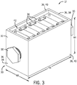
FIG. 3 is a perspective view of an embodiment of the housing system enclosing multiple prismatic cells; -
FIG. 4 is an exploded view of the embodiment of the housing system ofFIG. 3 , having a cooling system; -
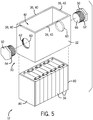
FIG. 5 is an exploded view of the embodiment of the housing system ofFIG. 3 , having compression plates; -
FIG. 6 is a top view of a not-claimed embodiment of the housing system, showing the housing system having one plug; -
FIG. 7 is a top view of an embodiment of the housing system, showing the housing system having two plugs; -
FIG. 8 is a perspective view of an embodiment of a plug, having a ratcheting mechanism as the detention mechanism according to the invention; -
FIG. 9A is a perspective view of a not-claimed embodiment of a plug, having a ribbed structure with a snap ring as the detention mechanism; -
FIG. 9B is a top view of a not-claimed embodiment of a casing incorporating the ribbed plug and snap ring; and -
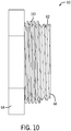
FIG. 10 is a side view of an embodiment of a plug, having a spring-loaded feature. - The term "xEV" is defined herein to include all of the following vehicles, or any variations or combinations thereof, that use electric power for all or a portion of their vehicular motive force. As will be appreciated by those skilled in the art, hybrid electric vehicles (HEVs) combine an internal combustion engine propulsion system and a battery-powered electric propulsion system. The term HEV may include any variation of a hybrid electric vehicle, such as micro-hybrid and mild hybrid systems, which disable the internal combustion engine when the vehicle is idling and utilize a battery system to continue powering the air conditioning unit, radio, or other electronics, as well as to kick-start the engine when propulsion is desired. The mild hybrid system may apply some level of power assist to the internal combustion engine, whereas the micro-hybrid system may not supply power assist to the internal combustion engine. A plug-in electric vehicle (PEV) is any vehicle that can be charged from an external source of electricity, such as wall sockets, and the energy stored in the rechargeable battery packs drives or contributes to drive the wheels. PEVs are a subcategory of electric vehicles that include all-electric or battery electric vehicles (BEVs), plug-in hybrid vehicles (PHEVs), and electric vehicle conversions of hybrid electric vehicles and conventional internal combustion engine vehicles. An electric vehicle (EV) is an all-electric vehicle that uses one or more motors powered by electric energy for its propulsion.
- As described in more detail below, disclosed herein are embodiments of battery module housing systems that may be used to compress one or more battery cells and that may be well suited to xEV applications. The cells of the battery module may be retained within a casing using a plug to hold the cells in place with respect to the casing. The plug may apply a force to the cells, placing them in compression within the casing. In addition to holding the cells in place, the compressive force may extend the life of the cells by limiting their ability to swell within the casing. Further, the use of the plug enables the amount of compressive force to be adjusted for a number of cells placed within the housing, despite variances in cell dimensions and tolerances. Furthermore, embodiments of the housing systems provided herein may include a one-piece casing. Particularly, use of a one-piece structure as the casing may create rigidity within the casing, as compared to a multi-piece casing. This may enable the one-piece casing to provide rigidity and compression for the prismatic cells when they swell during operation. Further, use of a one-piece structure reduces the part count of the battery module housing, thereby decreasing the time and cost of manufacturing associated with the battery modules.
- The battery modules that include the housing system with the one-piece casing and the plug may be easily configured for use in xEVs. In certain embodiments, the xEV may include at least one battery module, and each battery module may include the housing system having the simplified design. To ensure the casing and the plug of the housing system remain coupled, the casing may have a hole for the plug to feed through, and both the plug and the hole may include detention mechanisms on their interfacing surfaces. As such, the plug may securely couple to the casing and provide the ability to apply an adjustable compressive force to the cells within the housing.
- Turning now to the drawings,
FIG. 1 is a perspective view of avehicle 10 in the form of an automobile having abattery module 12 for contributing all or a portion of the motive power for thevehicle 10. Thebattery module 12 may be constructed from multiple individual prismatic cells and may include one or more housing systems as described above. Although illustrated as an automobile inFIG. 1 , the type of thevehicle 10 may be implementation-specific, and, accordingly, may differ in other embodiments, all of which are intended to fall within the scope of the present disclosure. For example, thevehicle 10 may be a truck, bus, industrial vehicle, motorcycle, recreational vehicle, boat, or any other type of vehicle that may benefit from the use of electric power for all or a portion of its propulsion power. For the purposes of the present disclosure, it should be noted that thebattery modules 12 and battery module accessories illustrated and described herein are particularly directed to providing and/or storing energy in xEVs. However, embodiments of thebattery modules 12 having the housing system may be utilized in other, non-vehicular applications as well. - Further, although the
battery module 12 is illustrated inFIG. 1 as being positioned in the trunk or rear of thevehicle 10, according to other embodiments, the location of thebattery module 12 may differ. For example, the position of thebattery module 12 may be selected based on the available space within thevehicle 10, the desired weight balance of thevehicle 10, the location of other components used with the battery module 12 (e.g., battery management modules, vents or cooling devices, etc.), and a variety of other implementation-specific considerations. - For purposes of discussion, it may be helpful to discuss the
battery module 12 with respect to a particular type of xEV, for example, an HEV.FIG. 2 illustrates a cutaway schematic of thevehicle 10 provided in the form of an HEV. In the illustrated embodiment, thebattery module 12 is provided toward the rear of thevehicle 10 near afuel tank 14. Thefuel tank 14 supplies fuel to aninternal combustion engine 16, which is provided for the instances when the HEV utilizes gasoline power to propel thevehicle 10. Anelectric motor 18, apower split device 20, and agenerator 22 are also provided as part of the vehicle drive system. Such an HEV may be powered or driven by only thebattery module 12, by only theengine 16, or by both thebattery module 12 and theengine 16. - As previously described, each
battery module 12 includes a housing system that encloses the cells of thebattery module 12. An embodiment of such ahousing system 30 is illustrated inFIG. 3 . Thehousing system 30 generally includes an electrically insulatingcasing 32 that encloses one or moreprismatic cells 34. Thecasing 32 may be designed to surround or enclose any desired number ofprismatic cells 34. As can be understood, electrically insulating dividers may be placed between thecells 34 in the case that thecasing 32 and/or thecells 34 are polarized. As shown, thecasing 32 of thehousing system 30 may be constructed from fourwalls 36 generally arranged as a box without a top or bottom. Of the fourwalls 36, two end walls 38 may be parallel to one another, and two side walls 40 may be parallel to one another, so that thewalls 36 create a rectangularinternal space 42 within thecasing 32 that accommodates thecells 34. The end walls 38 and side walls 40 may have anequal height 44. However, alength 46 of the side walls 40 may be greater than alength 48 of the end walls 38 to accommodate multipleprismatic cells 34 in a face-to-face arrangement. Thelengths walls 36 may be adjusted to accommodate a different number or arrangement of thecells 34. - In certain embodiments, the
casing 32 may be formed as a single piece. Creating thecasing 32 as a single piece may increase the strength of thecasing 32, thereby enabling thecasing 32 to provide rigidity for thecells 34 as they swell during operation. The structural stability of the single-piece casing 32 may apply compression to thecells 34 as they swell, decreasing the possibility of changing the internal geometry of thecells 34. This may preserve the product life and efficiency of thecells 34. Further, a single-piece casing 32 decreases the part count associated with thehousing system 30 and decreases the number of manufacturing steps needed to create thecasing 32. For example, the one-piece casing 32 may be created in a single step by injection molding of a thermoplastic material, thereby reducing costs associated with manufacturing for thebattery module 12 and making the resultingvehicle 10 more affordable for consumers. Thecasing 32 may be formed to include a hole (seeFIG. 4 ) in at least one end wall 38 to accommodate aplug 50. The hole may be formed simultaneously with thecasing 32 to reduce manufacturing steps/complexity. For example, polyvinyl chloride (PVC) or a similar thermoplastic may be used to form the one-piece casing 32. - To provide a better understanding of how the
plug 50 and other components fit within thecasing 32,FIG. 4 provides an exploded view of an embodiment of thehousing system 30. As previously described, thecasing 32 includesholes 60 to house theplugs 50. In the depicted embodiment, each end wall 38 includes thehole 60 at a generally central location. Theholes 60 enable theplugs 50 to contact and apply compression to thecells 34.Detention mechanisms 62 on the surface of theholes 60 enable theplugs 50 to securely couple to theholes 60 and translate axially through theholes 60. This axial translation may be used to adjust the location of theplugs 36 within theholes 60, enabling the amount of compressive force applied to thecells 34 to be adjustable. It may be desirable to adjust the amount of compressive force applied to thecells 34 to enable thehousing system 30 to accommodate variances within the dimensions of thecells 34. For example, if thecasing 32 accommodates eightcells 34 and each cell is manufactured to a tolerance of ±1/16th of an inch (1.5875 mm), there may be up to ½ of an inch (12.7 mm) that thehousing system 30 must accommodate. Accordingly, the adjustable compressive force may enable the design of thehousing system 30 to be robust with respect to the tolerances and variances of the multipleprismatic cells 34. - Each
plug 50 includes ahead portion 64 and abody portion 66. Thebody portion 66 may be inserted into thehole 60 externally to thecasing 32. Accordingly, thedetention mechanism 62 on the body portion of theplug 50 may mate with thedetention mechanism 62 in thehole 60 to couple theplug 50 to thecasing 32. Although shown as not-claimed matching threaded surfaces inFIG. 4 , thedetention mechanism 62 utilizes a ratchet and pawl system according to the invention. In a not-claimed embodiment, thedetention mechanism 62 may utilize a rib and snap-fit ring system, or another suitable system. A force and/or torque may be applied to thehead portion 64 to translate theplug 50 within thecasing 32, resulting in axial movement of theplug 50. As such, the distance that thebody portion 66 of theplug 50 extends into theinternal space 50 of thecasing 32 may be adjustable, thereby enabling theplug 50 to provide adjustable compressive force to thecells 34 within theinternal space 50. - The
head portion 64 may have a larger cross-section than thebody portion 66 and thehole 60 such that it cannot pass through thecasing 32. Further, thehead portion 64 may have a different geometry than thebody portion 66 and thehole 60. For example, thehead portion 64 may have a geometry that can withstand the force and/or torque applied to thehead portion 64. For example, thehead portion 64 of theplugs 50 may be fastened to thecasing 32 using an automated system or by hand. - The embodiment of the
housing system 30 inFIG. 4 further includes acooling system 68. Because thecasing 32 does not include a bottom piece, thecooling system 68 may have access to, or be in direct contact with, the bottom of thecells 34. Thus, thecooling system 68 may dissipate heat generated by chemical reactions within thecells 34. The use of thecooling system 68 may improve the reliability of thebattery module 12 by preventing thecells 34 from overheating. - The
cooling system 68 may include a liquid or gas coolant circuit, a cooling plate, a heat sink, a fan, a finned structure, or a combination thereof. - To more evenly distribute the compressive force exerted by the
plugs 50, thehousing system 30 may includecompression plates 80. Accordingly,FIG. 5 depicts thehousing system 30 with twocompression plates 80. Thecompression plates 80 may be rigid plastic plates that are placed at each end of the face-to-face cell 34 stack. In this way, thebody portion 66 of theplugs 50 may apply force to thecompression plates 80 instead of applying force to thecells 34 directly. By applying the force to therigid compression plates 80 instead of thecells 34, the compressive force from theplug 50 is applied over the entire surface area of the face of thecell 34, thereby reducing the possibility of damaging thecells 34 with the application of a concentrated force. When included in thehousing system 30, the compression plates may generally be located where aplug 50 contacts acell 34 or where acell 34 contacts thecasing 32. Thecompression plates 80 may be rectangular, circular, triangular, or any other suitable geometry for even force transmission. Particularly, thecompression plates 80 may be included in thehousing system 30 when even compressive force transmission is a primary goal of thehousing system 30, as opposed to reduced part count and/or manufacturing minimization. - An assembled top-view of the
battery module 12 is provided inFIGS. 6 and 7 . These views depict how thecells 34 may fit within the components of thehousing system 30. For example, thecells 34 may fit tightly within thelength 46 from end wall 38 to end wall 38. Within thelength 48, the fit between thecells 34 and the casing may be loose enough to allow thecells 34 to be placed into thecasing 32 via the open top. In this way, any group of a set number ofcells 34 may be housed within a mass-produced version of thecasing 32, and slight variances in the dimensions of thecells 34 and/or thecasing 32 may not affect how thecells 34 fit within thecasing 32. Although not shown, the fit along thelength 46 provides the option of includingcompression plates 80 within thecasing 32. As depicted in not-claimedFIG. 6 , asingle plug 50 applies compressive force to thecells 34 from the end wall 38. However, if it is desirable to provide increased compressive force to thecells 34, twoplugs FIG. 7 . In alternative not-claimed embodiments,multiple holes 60 and plugs 50 may be used at each end wall 38. Accordingly, theplugs 50 may vary in length depending on the number ofcells 34 within thehousing 32, the presence ofcompression plates 80 within thehousing 32, the variance amongcell 34 dimensions, the thickness of the end walls 40, and/or other design considerations. Further, although shown as not-claimed threaded features, theplugs 50 may incorporatedifferent detention mechanisms 62 to fix theplugs holes 60. - One
alternative detention mechanism 62 according to the invention for holding theplug 50 in place within thecasing 32 is aratcheting system 90, as depicted inFIG. 8 . For example, thebody portion 66 of theplug 50 may include multiple rows oftriangular teeth 92 that extend along thebody portion 66 parallel to the axis for theplug 50. Each row ofteeth 92 may interact with apawl 94 disposed within thehole 60 in thecasing 32. Using theratcheting system 90, theplug 50 may only be able to translate axially into thehole 60, being fixed in position by thepawl 94. Accordingly, as thecells 34 begin to swell, theplug 50 may not back out of thehole 60, thereby applying compression to thecells 34. - In a different not-claimed embodiment, depicted in
FIGS. 9A and 9B , thedetention mechanism 62 may utilizeribs 100 and a snap-fit ring 102 to hold theplug 50 in place within thecasing 32. As shown inFIG. 9A ,multiple ribs 100 may radially project from thebody 66 of theplug 50. Accordingly, the space between theribs 100 may formtrenches 102. Thetrenches 102 may accommodate a snap-fit ring 104. InFIG. 9B , the snap-fit ring 104 is shown disposed in one of thetrenches 102, such that thebody portion 66 of theplug 50 is extending a desired distance into the rectangularinner space 42 of thecasing 32. In this way, theplug 50 may apply compression to thecells 34 as they begin to swell within thecasing 32. - The
plug 50 may incorporate additional features to determine how it applies compression to thecells 34. For example, as depicted inFIG. 10 , theplug 50 may include acoil spring 110 to increase the compressive force applied to thecells 34 or allow limited movement of thecells 34 when they begin to expand. Thecoil spring 90 may fit between the inner surface of thecasing 32 and the face of theend cell 34 orcompression plate 80. Theplugs 50 may include other components to facilitate compression, such as polymer gaskets, leaf springs, and other means of compression. Such compression components may be used when applying compression to thecells 34 is the primary goal of thehousing system 30, as opposed to minimizing manufacturing costs and part count. - References herein to the positions of elements (e.g., "top," "bottom," "above," "below," etc.) are merely used to describe the orientation of various elements in the figures. It should be noted that the orientation of various elements may differ according to other embodiments, and that such variations are intended to be encompassed by the present disclosure.
Claims (11)
- A housing system (30) for one or more battery cells, the housing system (30) comprising:- a casing (32) forming a generally rectangular internal space (42), having opposing end pieces (38);- two holes (60) each extending through one of the end pieces (38) in a central location of the end piece (38); and- two plugs (50) each having a head portion and a body portion, wherein the body portion is configured to extend through one of the holes (60) to contact one of the battery cells, and the body portion has a detention mechanism (62) comprising a ratcheting mechanism having at least one set of triangular teeth disposed axially along the body portion of the plug (50) and having at least one pawl to engage the teeth disposed about the hole (50) of the end piece (38) of the casing (32) so as to fix its position to provide a compressive force on the battery cells.
- The housing system (30) of claim 1,
wherein the casing (32) is configured to enclose multiple prismatic cells (34). - The housing system (30) of claim 1,
wherein the casing (32) is of single-piece construction. - The housing system (30) of claim 1,
wherein the casing (32) is formed of a plastic material. - The housing system (30) of claim 1,
wherein the plug (30) is configured to be placed within the hole (30) and have torque applied to the head portion to apply a compressive force to the battery cells within the casing (32). - The housing system (30) of claim 1,
wherein the plug (50) comprises a spring. - The housing system (30) of claim 1, having a cooling system (68) disposed below the casing (32), wherein the cooling system (68) has direct access to the bottom of the cells.
- The housing system (30) of claim 1, having two rectangular compression plates (80), each located within the casing (32) adjacent to each end piece (38) and each compression plate (80) is positioned between with the body portion of the plug (50) and the multiple prismatic cells (34).
- A battery module, comprising:- the housing system (30) of any of the preceding claims; and- a stack of battery cells, each being generally rectangular in shape and having a rigid container, the stack of battery cells fitting within the rectangular internal space of the casing (32).
- An xEV, which is a vehicle which uses electric power for all or a portion of its vehicular motive force, and which includes the battery module of claim 9.
- A method for applying compression to a stack of electrochemical cells comprising:- providing the housing system (30) of any of claims 1 to 8;- placing the stack of electrochemical cells within the rigid casing;- positioning the plugs within holes in the rigid casing; and- applying a desired amount of force to the plugs (50), wherein the plugs (50) apply a compressive force to an end of the stack of electrochemical cells within the casing (32).
Applications Claiming Priority (3)
| Application Number | Priority Date | Filing Date | Title |
|---|---|---|---|
| US201161556747P | 2011-11-07 | 2011-11-07 | |
| US13/665,613 US20130115496A1 (en) | 2011-11-07 | 2012-10-31 | One-piece housing with plugs for prismatic cell assembly |
| PCT/US2012/063693 WO2013070593A1 (en) | 2011-11-07 | 2012-11-06 | One-piece housing with plugs for prismatic cell assembly |
Publications (2)
| Publication Number | Publication Date |
|---|---|
| EP2777085A1 EP2777085A1 (en) | 2014-09-17 |
| EP2777085B1 true EP2777085B1 (en) | 2020-01-22 |
Family
ID=48223896
Family Applications (1)
| Application Number | Title | Priority Date | Filing Date |
|---|---|---|---|
| EP12799672.6A Active EP2777085B1 (en) | 2011-11-07 | 2012-11-06 | One-piece housing with plugs for prismatic cell assembly |
Country Status (4)
| Country | Link |
|---|---|
| US (1) | US20130115496A1 (en) |
| EP (1) | EP2777085B1 (en) |
| CN (1) | CN103999258A (en) |
| WO (1) | WO2013070593A1 (en) |
Families Citing this family (20)
| Publication number | Priority date | Publication date | Assignee | Title |
|---|---|---|---|---|
| CN103400948B (en) * | 2013-08-08 | 2015-10-28 | 安徽江淮汽车股份有限公司 | Hold the outer warehouse of electric commercial vehicle battery pack and the fixed structure of battery pack |
| US9831482B2 (en) | 2013-09-06 | 2017-11-28 | Johnson Controls Technology Company | Battery module lid system and method |
| US9318751B2 (en) * | 2014-03-31 | 2016-04-19 | Ford Global Technologies, Llc | Traction battery assembly with spring component |
| EP3171427B1 (en) * | 2014-07-14 | 2019-12-11 | Kaneka Corporation | Cell pack and power storage unit including plurality of same |
| CN105789505A (en) * | 2014-12-25 | 2016-07-20 | 宁德时代新能源科技股份有限公司 | Power battery pack grouping structure |
| JP6536679B2 (en) * | 2015-09-03 | 2019-07-03 | 株式会社村田製作所 | battery |
| JP6759571B2 (en) * | 2015-12-15 | 2020-09-23 | 株式会社豊田自動織機 | Battery pack |
| DE102016103841A1 (en) * | 2016-03-03 | 2017-09-07 | Johnson Controls Advanced Power Solutions Gmbh | Attachment of electrochemical cells in a housing of a battery module |
| DE102017102064A1 (en) * | 2016-08-29 | 2018-03-01 | Erhardt GmbH Fahrzeug und Teile | ELECTRIC WAGON |
| US20180105062A1 (en) * | 2016-10-14 | 2018-04-19 | Inevit, Inc. | Battery module compartment chamber and battery module mounting area of an energy storage system and method thereof |
| CN114583369A (en) * | 2016-11-09 | 2022-06-03 | Cps 科技控股有限公司 | battery pack |
| CN108075063B (en) | 2016-11-09 | 2021-06-29 | Cps科技控股有限公司 | Battery pack with exhaust passage |
| CN108075062B (en) | 2016-11-09 | 2021-08-06 | Cps科技控股有限公司 | Battery pack with two end plates |
| CN108075060B (en) | 2016-11-09 | 2021-04-23 | Cps科技控股有限公司 | Battery pack having a case made of two materials |
| KR102250204B1 (en) * | 2018-03-07 | 2021-05-10 | 주식회사 엘지화학 | Battery module, battery pack comprising the battery module and vehicle comprising the battery pack |
| DE102018114226A1 (en) * | 2018-06-14 | 2019-12-19 | Volkswagen Aktiengesellschaft | Load-bearing battery module for a motor vehicle and motor vehicle |
| JP7053447B2 (en) * | 2018-12-21 | 2022-04-12 | トヨタ自動車株式会社 | Battery pack |
| CN209747611U (en) * | 2019-06-28 | 2019-12-06 | 江苏时代新能源科技有限公司 | Battery module |
| FR3131447A1 (en) | 2021-12-28 | 2023-06-30 | Commissariat à l'Energie Atomique et aux Energies Alternatives | ELECTROCHEMICAL ACCUMULATOR MODULE CONTAINED BY COMPRESSION BAG |
| DE102023202549A1 (en) * | 2023-03-22 | 2024-09-26 | Robert Bosch Gesellschaft mit beschränkter Haftung | Fastening arrangement for fastening a functional component to a component of an electrochemical energy converter and electrochemical energy converter |
Family Cites Families (14)
| Publication number | Priority date | Publication date | Assignee | Title |
|---|---|---|---|---|
| GB346862A (en) * | 1930-01-23 | 1931-04-23 | Victor England Richards | Improvements in or relating to electric batteries composed of single cells or elements adapted to be connected in series or parallel |
| US2905414A (en) * | 1953-12-28 | 1959-09-22 | Frank P Zierden | Christmas tree stand |
| US2796787A (en) * | 1955-04-01 | 1957-06-25 | Irving E Aske | Doubly padded face-plates for vise jaws |
| US4747590A (en) * | 1986-10-27 | 1988-05-31 | Yang Tai Her | Interconnected C-clamps and tensioning means therefor |
| US4960264A (en) * | 1989-05-09 | 1990-10-02 | Safe-T-Jack, Inc. | Alignment and release mechanism for two-part jack system |
| US6162559A (en) * | 1998-09-21 | 2000-12-19 | Douglas Battery Manufacturing Company | Compressed battery system for motive power applications |
| US6370817B1 (en) * | 2000-07-28 | 2002-04-16 | Alvin E. Brooks | Tree bracing system |
| US20050095485A1 (en) * | 2003-10-31 | 2005-05-05 | 3M Innovative Properties Company | Fuel cell end plate assembly |
| US20060093890A1 (en) * | 2004-10-29 | 2006-05-04 | Steinbroner Matthew P | Fuel cell stack compression systems, and fuel cell stacks and fuel cell systems incorporating the same |
| PL2191524T3 (en) * | 2007-08-14 | 2019-11-29 | Battery Patent Trust | Battery module |
| JPWO2009125544A1 (en) * | 2008-04-11 | 2011-07-28 | 川崎重工業株式会社 | Sealed prismatic battery and battery module using the same |
| DE202009011986U1 (en) * | 2009-08-28 | 2009-12-10 | Illinois Tool Works Inc., Glenview | Device for connecting two components |
| DE102010013034A1 (en) * | 2010-03-26 | 2011-09-29 | Daimler Ag | Battery for storing and supplying electrical power for driving e.g. passenger car, has tensioning arrangements bracing cell stack between two portions of battery housing, and flat individual cells braced to cell stack through arrangements |
| US20130022853A1 (en) * | 2011-07-20 | 2013-01-24 | Robb Protheroe | Modular Variable Compression Thermal Management Battery Retaining System |
-
2012
- 2012-10-31 US US13/665,613 patent/US20130115496A1/en not_active Abandoned
- 2012-11-06 WO PCT/US2012/063693 patent/WO2013070593A1/en not_active Ceased
- 2012-11-06 CN CN201280062752.XA patent/CN103999258A/en active Pending
- 2012-11-06 EP EP12799672.6A patent/EP2777085B1/en active Active
Non-Patent Citations (1)
| Title |
|---|
| None * |
Also Published As
| Publication number | Publication date |
|---|---|
| EP2777085A1 (en) | 2014-09-17 |
| US20130115496A1 (en) | 2013-05-09 |
| WO2013070593A1 (en) | 2013-05-16 |
| CN103999258A (en) | 2014-08-20 |
Similar Documents
| Publication | Publication Date | Title |
|---|---|---|
| EP2777085B1 (en) | One-piece housing with plugs for prismatic cell assembly | |
| US11063326B2 (en) | Biasing features for a battery module | |
| US11462795B2 (en) | Battery module having a cell assembly | |
| EP3201035B1 (en) | Bus bar assembly carrier | |
| EP3491686B1 (en) | Cell assembly for a battery module | |
| US11309604B2 (en) | Thermal epoxy and positioning of electrochemical cells | |
| US9859532B2 (en) | Battery module and method incorporating exterior casing and liner | |
| KR20130069472A (en) | Battery module assembly of improved reliability and battery pack employed with the same | |
| US20220037734A1 (en) | Mounting clip for printed circuit board | |
| EP3195385B1 (en) | Recessed terminal in module body | |
| CN107925023B (en) | System and method for a reinforcement column within a module body | |
| CN221508352U (en) | Insert structure, battery and power device | |
| EP3243233B1 (en) | Biasing features for a battery module | |
| JP7840598B1 (en) | Battery pack storage case | |
| CN118867538B (en) | Battery device and power device | |
| CN112103585B (en) | Bias features for battery modules |
Legal Events
| Date | Code | Title | Description |
|---|---|---|---|
| PUAI | Public reference made under article 153(3) epc to a published international application that has entered the european phase |
Free format text: ORIGINAL CODE: 0009012 |
|
| 17P | Request for examination filed |
Effective date: 20140507 |
|
| AK | Designated contracting states |
Kind code of ref document: A1 Designated state(s): AL AT BE BG CH CY CZ DE DK EE ES FI FR GB GR HR HU IE IS IT LI LT LU LV MC MK MT NL NO PL PT RO RS SE SI SK SM TR |
|
| DAX | Request for extension of the european patent (deleted) | ||
| STAA | Information on the status of an ep patent application or granted ep patent |
Free format text: STATUS: EXAMINATION IS IN PROGRESS |
|
| 17Q | First examination report despatched |
Effective date: 20180413 |
|
| RIC1 | Information provided on ipc code assigned before grant |
Ipc: H01M 2/10 20060101AFI20190529BHEP Ipc: H01M 10/625 20140101ALI20190529BHEP Ipc: H01M 10/04 20060101ALI20190529BHEP Ipc: H01M 10/6554 20140101ALI20190529BHEP Ipc: H01M 10/0585 20100101ALI20190529BHEP Ipc: H01M 10/647 20140101ALI20190529BHEP |
|
| GRAP | Despatch of communication of intention to grant a patent |
Free format text: ORIGINAL CODE: EPIDOSNIGR1 |
|
| STAA | Information on the status of an ep patent application or granted ep patent |
Free format text: STATUS: GRANT OF PATENT IS INTENDED |
|
| INTG | Intention to grant announced |
Effective date: 20190802 |
|
| GRAS | Grant fee paid |
Free format text: ORIGINAL CODE: EPIDOSNIGR3 |
|
| GRAA | (expected) grant |
Free format text: ORIGINAL CODE: 0009210 |
|
| STAA | Information on the status of an ep patent application or granted ep patent |
Free format text: STATUS: THE PATENT HAS BEEN GRANTED |
|
| RAP1 | Party data changed (applicant data changed or rights of an application transferred) |
Owner name: CPS TECHNOLOGY HOLDINGS LLC |
|
| AK | Designated contracting states |
Kind code of ref document: B1 Designated state(s): AL AT BE BG CH CY CZ DE DK EE ES FI FR GB GR HR HU IE IS IT LI LT LU LV MC MK MT NL NO PL PT RO RS SE SI SK SM TR |
|
| REG | Reference to a national code |
Ref country code: GB Ref legal event code: FG4D |
|
| REG | Reference to a national code |
Ref country code: CH Ref legal event code: EP |
|
| REG | Reference to a national code |
Ref country code: DE Ref legal event code: R096 Ref document number: 602012067437 Country of ref document: DE |
|
| REG | Reference to a national code |
Ref country code: AT Ref legal event code: REF Ref document number: 1227511 Country of ref document: AT Kind code of ref document: T Effective date: 20200215 |
|
| REG | Reference to a national code |
Ref country code: IE Ref legal event code: FG4D |
|
| REG | Reference to a national code |
Ref country code: NL Ref legal event code: MP Effective date: 20200122 |
|
| REG | Reference to a national code |
Ref country code: LT Ref legal event code: MG4D |
|
| PG25 | Lapsed in a contracting state [announced via postgrant information from national office to epo] |
Ref country code: RS Free format text: LAPSE BECAUSE OF FAILURE TO SUBMIT A TRANSLATION OF THE DESCRIPTION OR TO PAY THE FEE WITHIN THE PRESCRIBED TIME-LIMIT Effective date: 20200122 Ref country code: FI Free format text: LAPSE BECAUSE OF FAILURE TO SUBMIT A TRANSLATION OF THE DESCRIPTION OR TO PAY THE FEE WITHIN THE PRESCRIBED TIME-LIMIT Effective date: 20200122 Ref country code: NO Free format text: LAPSE BECAUSE OF FAILURE TO SUBMIT A TRANSLATION OF THE DESCRIPTION OR TO PAY THE FEE WITHIN THE PRESCRIBED TIME-LIMIT Effective date: 20200422 Ref country code: PT Free format text: LAPSE BECAUSE OF FAILURE TO SUBMIT A TRANSLATION OF THE DESCRIPTION OR TO PAY THE FEE WITHIN THE PRESCRIBED TIME-LIMIT Effective date: 20200614 Ref country code: NL Free format text: LAPSE BECAUSE OF FAILURE TO SUBMIT A TRANSLATION OF THE DESCRIPTION OR TO PAY THE FEE WITHIN THE PRESCRIBED TIME-LIMIT Effective date: 20200122 |
|
| PG25 | Lapsed in a contracting state [announced via postgrant information from national office to epo] |
Ref country code: LV Free format text: LAPSE BECAUSE OF FAILURE TO SUBMIT A TRANSLATION OF THE DESCRIPTION OR TO PAY THE FEE WITHIN THE PRESCRIBED TIME-LIMIT Effective date: 20200122 Ref country code: SE Free format text: LAPSE BECAUSE OF FAILURE TO SUBMIT A TRANSLATION OF THE DESCRIPTION OR TO PAY THE FEE WITHIN THE PRESCRIBED TIME-LIMIT Effective date: 20200122 Ref country code: IS Free format text: LAPSE BECAUSE OF FAILURE TO SUBMIT A TRANSLATION OF THE DESCRIPTION OR TO PAY THE FEE WITHIN THE PRESCRIBED TIME-LIMIT Effective date: 20200522 Ref country code: GR Free format text: LAPSE BECAUSE OF FAILURE TO SUBMIT A TRANSLATION OF THE DESCRIPTION OR TO PAY THE FEE WITHIN THE PRESCRIBED TIME-LIMIT Effective date: 20200423 Ref country code: BG Free format text: LAPSE BECAUSE OF FAILURE TO SUBMIT A TRANSLATION OF THE DESCRIPTION OR TO PAY THE FEE WITHIN THE PRESCRIBED TIME-LIMIT Effective date: 20200422 Ref country code: HR Free format text: LAPSE BECAUSE OF FAILURE TO SUBMIT A TRANSLATION OF THE DESCRIPTION OR TO PAY THE FEE WITHIN THE PRESCRIBED TIME-LIMIT Effective date: 20200122 |
|
| REG | Reference to a national code |
Ref country code: DE Ref legal event code: R097 Ref document number: 602012067437 Country of ref document: DE |
|
| PG25 | Lapsed in a contracting state [announced via postgrant information from national office to epo] |
Ref country code: SM Free format text: LAPSE BECAUSE OF FAILURE TO SUBMIT A TRANSLATION OF THE DESCRIPTION OR TO PAY THE FEE WITHIN THE PRESCRIBED TIME-LIMIT Effective date: 20200122 Ref country code: LT Free format text: LAPSE BECAUSE OF FAILURE TO SUBMIT A TRANSLATION OF THE DESCRIPTION OR TO PAY THE FEE WITHIN THE PRESCRIBED TIME-LIMIT Effective date: 20200122 Ref country code: SK Free format text: LAPSE BECAUSE OF FAILURE TO SUBMIT A TRANSLATION OF THE DESCRIPTION OR TO PAY THE FEE WITHIN THE PRESCRIBED TIME-LIMIT Effective date: 20200122 Ref country code: ES Free format text: LAPSE BECAUSE OF FAILURE TO SUBMIT A TRANSLATION OF THE DESCRIPTION OR TO PAY THE FEE WITHIN THE PRESCRIBED TIME-LIMIT Effective date: 20200122 Ref country code: DK Free format text: LAPSE BECAUSE OF FAILURE TO SUBMIT A TRANSLATION OF THE DESCRIPTION OR TO PAY THE FEE WITHIN THE PRESCRIBED TIME-LIMIT Effective date: 20200122 Ref country code: CZ Free format text: LAPSE BECAUSE OF FAILURE TO SUBMIT A TRANSLATION OF THE DESCRIPTION OR TO PAY THE FEE WITHIN THE PRESCRIBED TIME-LIMIT Effective date: 20200122 Ref country code: RO Free format text: LAPSE BECAUSE OF FAILURE TO SUBMIT A TRANSLATION OF THE DESCRIPTION OR TO PAY THE FEE WITHIN THE PRESCRIBED TIME-LIMIT Effective date: 20200122 Ref country code: EE Free format text: LAPSE BECAUSE OF FAILURE TO SUBMIT A TRANSLATION OF THE DESCRIPTION OR TO PAY THE FEE WITHIN THE PRESCRIBED TIME-LIMIT Effective date: 20200122 |
|
| REG | Reference to a national code |
Ref country code: AT Ref legal event code: MK05 Ref document number: 1227511 Country of ref document: AT Kind code of ref document: T Effective date: 20200122 |
|
| PLBE | No opposition filed within time limit |
Free format text: ORIGINAL CODE: 0009261 |
|
| REG | Reference to a national code |
Ref country code: DE Ref legal event code: R079 Ref document number: 602012067437 Country of ref document: DE Free format text: PREVIOUS MAIN CLASS: H01M0002100000 Ipc: H01M0050200000 |
|
| STAA | Information on the status of an ep patent application or granted ep patent |
Free format text: STATUS: NO OPPOSITION FILED WITHIN TIME LIMIT |
|
| 26N | No opposition filed |
Effective date: 20201023 |
|
| PG25 | Lapsed in a contracting state [announced via postgrant information from national office to epo] |
Ref country code: IT Free format text: LAPSE BECAUSE OF FAILURE TO SUBMIT A TRANSLATION OF THE DESCRIPTION OR TO PAY THE FEE WITHIN THE PRESCRIBED TIME-LIMIT Effective date: 20200122 Ref country code: AT Free format text: LAPSE BECAUSE OF FAILURE TO SUBMIT A TRANSLATION OF THE DESCRIPTION OR TO PAY THE FEE WITHIN THE PRESCRIBED TIME-LIMIT Effective date: 20200122 |
|
| PG25 | Lapsed in a contracting state [announced via postgrant information from national office to epo] |
Ref country code: SI Free format text: LAPSE BECAUSE OF FAILURE TO SUBMIT A TRANSLATION OF THE DESCRIPTION OR TO PAY THE FEE WITHIN THE PRESCRIBED TIME-LIMIT Effective date: 20200122 Ref country code: PL Free format text: LAPSE BECAUSE OF FAILURE TO SUBMIT A TRANSLATION OF THE DESCRIPTION OR TO PAY THE FEE WITHIN THE PRESCRIBED TIME-LIMIT Effective date: 20200122 |
|
| PG25 | Lapsed in a contracting state [announced via postgrant information from national office to epo] |
Ref country code: MC Free format text: LAPSE BECAUSE OF FAILURE TO SUBMIT A TRANSLATION OF THE DESCRIPTION OR TO PAY THE FEE WITHIN THE PRESCRIBED TIME-LIMIT Effective date: 20200122 |
|
| REG | Reference to a national code |
Ref country code: CH Ref legal event code: PL |
|
| PG25 | Lapsed in a contracting state [announced via postgrant information from national office to epo] |
Ref country code: LU Free format text: LAPSE BECAUSE OF NON-PAYMENT OF DUE FEES Effective date: 20201106 |
|
| REG | Reference to a national code |
Ref country code: BE Ref legal event code: MM Effective date: 20201130 |
|
| PG25 | Lapsed in a contracting state [announced via postgrant information from national office to epo] |
Ref country code: CH Free format text: LAPSE BECAUSE OF NON-PAYMENT OF DUE FEES Effective date: 20201130 Ref country code: LI Free format text: LAPSE BECAUSE OF NON-PAYMENT OF DUE FEES Effective date: 20201130 |
|
| PG25 | Lapsed in a contracting state [announced via postgrant information from national office to epo] |
Ref country code: IE Free format text: LAPSE BECAUSE OF NON-PAYMENT OF DUE FEES Effective date: 20201106 |
|
| PG25 | Lapsed in a contracting state [announced via postgrant information from national office to epo] |
Ref country code: TR Free format text: LAPSE BECAUSE OF FAILURE TO SUBMIT A TRANSLATION OF THE DESCRIPTION OR TO PAY THE FEE WITHIN THE PRESCRIBED TIME-LIMIT Effective date: 20200122 Ref country code: MT Free format text: LAPSE BECAUSE OF FAILURE TO SUBMIT A TRANSLATION OF THE DESCRIPTION OR TO PAY THE FEE WITHIN THE PRESCRIBED TIME-LIMIT Effective date: 20200122 Ref country code: CY Free format text: LAPSE BECAUSE OF FAILURE TO SUBMIT A TRANSLATION OF THE DESCRIPTION OR TO PAY THE FEE WITHIN THE PRESCRIBED TIME-LIMIT Effective date: 20200122 |
|
| PG25 | Lapsed in a contracting state [announced via postgrant information from national office to epo] |
Ref country code: MK Free format text: LAPSE BECAUSE OF FAILURE TO SUBMIT A TRANSLATION OF THE DESCRIPTION OR TO PAY THE FEE WITHIN THE PRESCRIBED TIME-LIMIT Effective date: 20200122 Ref country code: AL Free format text: LAPSE BECAUSE OF FAILURE TO SUBMIT A TRANSLATION OF THE DESCRIPTION OR TO PAY THE FEE WITHIN THE PRESCRIBED TIME-LIMIT Effective date: 20200122 |
|
| PG25 | Lapsed in a contracting state [announced via postgrant information from national office to epo] |
Ref country code: BE Free format text: LAPSE BECAUSE OF NON-PAYMENT OF DUE FEES Effective date: 20201130 |
|
| P01 | Opt-out of the competence of the unified patent court (upc) registered |
Free format text: CASE NUMBER: APP_745/2025 Effective date: 20250108 |
|
| PGFP | Annual fee paid to national office [announced via postgrant information from national office to epo] |
Ref country code: DE Payment date: 20251128 Year of fee payment: 14 |
|
| PGFP | Annual fee paid to national office [announced via postgrant information from national office to epo] |
Ref country code: GB Payment date: 20251127 Year of fee payment: 14 |
|
| PGFP | Annual fee paid to national office [announced via postgrant information from national office to epo] |
Ref country code: FR Payment date: 20251125 Year of fee payment: 14 |