EP0989618A1 - A battery housing and system for motive power applications - Google Patents
A battery housing and system for motive power applications Download PDFInfo
- Publication number
- EP0989618A1 EP0989618A1 EP19990307369 EP99307369A EP0989618A1 EP 0989618 A1 EP0989618 A1 EP 0989618A1 EP 19990307369 EP19990307369 EP 19990307369 EP 99307369 A EP99307369 A EP 99307369A EP 0989618 A1 EP0989618 A1 EP 0989618A1
- Authority
- EP
- European Patent Office
- Prior art keywords
- battery
- compartment
- cells
- compression
- stack
- Prior art date
- Legal status (The legal status is an assumption and is not a legal conclusion. Google has not performed a legal analysis and makes no representation as to the accuracy of the status listed.)
- Granted
Links
Images


Classifications
-
- H—ELECTRICITY
- H01—ELECTRIC ELEMENTS
- H01M—PROCESSES OR MEANS, e.g. BATTERIES, FOR THE DIRECT CONVERSION OF CHEMICAL ENERGY INTO ELECTRICAL ENERGY
- H01M10/00—Secondary cells; Manufacture thereof
- H01M10/42—Methods or arrangements for servicing or maintenance of secondary cells or secondary half-cells
- H01M10/46—Accumulators structurally combined with charging apparatus
-
- H—ELECTRICITY
- H01—ELECTRIC ELEMENTS
- H01M—PROCESSES OR MEANS, e.g. BATTERIES, FOR THE DIRECT CONVERSION OF CHEMICAL ENERGY INTO ELECTRICAL ENERGY
- H01M50/00—Constructional details or processes of manufacture of the non-active parts of electrochemical cells other than fuel cells, e.g. hybrid cells
- H01M50/20—Mountings; Secondary casings or frames; Racks, modules or packs; Suspension devices; Shock absorbers; Transport or carrying devices; Holders
- H01M50/204—Racks, modules or packs for multiple batteries or multiple cells
- H01M50/207—Racks, modules or packs for multiple batteries or multiple cells characterised by their shape
- H01M50/209—Racks, modules or packs for multiple batteries or multiple cells characterised by their shape adapted for prismatic or rectangular cells
-
- H—ELECTRICITY
- H01—ELECTRIC ELEMENTS
- H01M—PROCESSES OR MEANS, e.g. BATTERIES, FOR THE DIRECT CONVERSION OF CHEMICAL ENERGY INTO ELECTRICAL ENERGY
- H01M50/00—Constructional details or processes of manufacture of the non-active parts of electrochemical cells other than fuel cells, e.g. hybrid cells
- H01M50/20—Mountings; Secondary casings or frames; Racks, modules or packs; Suspension devices; Shock absorbers; Transport or carrying devices; Holders
- H01M50/253—Mountings; Secondary casings or frames; Racks, modules or packs; Suspension devices; Shock absorbers; Transport or carrying devices; Holders adapted for specific cells, e.g. electrochemical cells operating at high temperature
-
- H—ELECTRICITY
- H01—ELECTRIC ELEMENTS
- H01M—PROCESSES OR MEANS, e.g. BATTERIES, FOR THE DIRECT CONVERSION OF CHEMICAL ENERGY INTO ELECTRICAL ENERGY
- H01M50/00—Constructional details or processes of manufacture of the non-active parts of electrochemical cells other than fuel cells, e.g. hybrid cells
- H01M50/20—Mountings; Secondary casings or frames; Racks, modules or packs; Suspension devices; Shock absorbers; Transport or carrying devices; Holders
- H01M50/289—Mountings; Secondary casings or frames; Racks, modules or packs; Suspension devices; Shock absorbers; Transport or carrying devices; Holders characterised by spacing elements or positioning means within frames, racks or packs
- H01M50/291—Mountings; Secondary casings or frames; Racks, modules or packs; Suspension devices; Shock absorbers; Transport or carrying devices; Holders characterised by spacing elements or positioning means within frames, racks or packs characterised by their shape
-
- H—ELECTRICITY
- H01—ELECTRIC ELEMENTS
- H01M—PROCESSES OR MEANS, e.g. BATTERIES, FOR THE DIRECT CONVERSION OF CHEMICAL ENERGY INTO ELECTRICAL ENERGY
- H01M10/00—Secondary cells; Manufacture thereof
- H01M10/04—Construction or manufacture in general
- H01M10/0468—Compression means for stacks of electrodes and separators
-
- H—ELECTRICITY
- H01—ELECTRIC ELEMENTS
- H01M—PROCESSES OR MEANS, e.g. BATTERIES, FOR THE DIRECT CONVERSION OF CHEMICAL ENERGY INTO ELECTRICAL ENERGY
- H01M10/00—Secondary cells; Manufacture thereof
- H01M10/06—Lead-acid accumulators
- H01M10/12—Construction or manufacture
- H01M10/121—Valve regulated lead acid batteries [VRLA]
-
- H—ELECTRICITY
- H01—ELECTRIC ELEMENTS
- H01M—PROCESSES OR MEANS, e.g. BATTERIES, FOR THE DIRECT CONVERSION OF CHEMICAL ENERGY INTO ELECTRICAL ENERGY
- H01M10/00—Secondary cells; Manufacture thereof
- H01M10/60—Heating or cooling; Temperature control
- H01M10/62—Heating or cooling; Temperature control specially adapted for specific applications
- H01M10/625—Vehicles
-
- H—ELECTRICITY
- H01—ELECTRIC ELEMENTS
- H01M—PROCESSES OR MEANS, e.g. BATTERIES, FOR THE DIRECT CONVERSION OF CHEMICAL ENERGY INTO ELECTRICAL ENERGY
- H01M10/00—Secondary cells; Manufacture thereof
- H01M10/60—Heating or cooling; Temperature control
- H01M10/65—Means for temperature control structurally associated with the cells
- H01M10/656—Means for temperature control structurally associated with the cells characterised by the type of heat-exchange fluid
- H01M10/6561—Gases
- H01M10/6562—Gases with free flow by convection only
-
- Y—GENERAL TAGGING OF NEW TECHNOLOGICAL DEVELOPMENTS; GENERAL TAGGING OF CROSS-SECTIONAL TECHNOLOGIES SPANNING OVER SEVERAL SECTIONS OF THE IPC; TECHNICAL SUBJECTS COVERED BY FORMER USPC CROSS-REFERENCE ART COLLECTIONS [XRACs] AND DIGESTS
- Y02—TECHNOLOGIES OR APPLICATIONS FOR MITIGATION OR ADAPTATION AGAINST CLIMATE CHANGE
- Y02E—REDUCTION OF GREENHOUSE GAS [GHG] EMISSIONS, RELATED TO ENERGY GENERATION, TRANSMISSION OR DISTRIBUTION
- Y02E60/00—Enabling technologies; Technologies with a potential or indirect contribution to GHG emissions mitigation
- Y02E60/10—Energy storage using batteries
-
- Y—GENERAL TAGGING OF NEW TECHNOLOGICAL DEVELOPMENTS; GENERAL TAGGING OF CROSS-SECTIONAL TECHNOLOGIES SPANNING OVER SEVERAL SECTIONS OF THE IPC; TECHNICAL SUBJECTS COVERED BY FORMER USPC CROSS-REFERENCE ART COLLECTIONS [XRACs] AND DIGESTS
- Y02—TECHNOLOGIES OR APPLICATIONS FOR MITIGATION OR ADAPTATION AGAINST CLIMATE CHANGE
- Y02P—CLIMATE CHANGE MITIGATION TECHNOLOGIES IN THE PRODUCTION OR PROCESSING OF GOODS
- Y02P70/00—Climate change mitigation technologies in the production process for final industrial or consumer products
- Y02P70/50—Manufacturing or production processes characterised by the final manufactured product
Definitions
- the present invention relates to battery cell tray or housing assemblies for motive power applications. More particularly, the invention relates to a battery cell tray or housing assembly having a battery compartment which is capable of holding and compressing a stack of valve-regulated lead-acid battery cells in a horizontal position.
- deep discharge refers to the extent to which a battery is discharged during service before being recharged.
- a shallow discharge application is one such as starting an automobile engine wherein the extent of discharge for each use is relatively small compared to the total battery capacity.
- the discharge is followed soon after by recharging. Over a large number of repeated cycles very little of the battery capacity is used prior to recharging.
- deep discharge duty cycles are characterized by drawing a substantial majority of the battery capacity before the battery is recharged.
- Typical motive power applications that require deep cycle capability include Class 1 electric rider trucks, Class 2 electric narrow isle trucks and Class 3 electric hand trucks.
- batteries installed in these types of vehicles must deliver a number of discharges during a year that may number in the hundreds.
- the cycle life of batteries used in these applications typically can range from 500-2000 total cycles so that the battery lasts a number of years before it needs to be replaced.
- flooded lead-acid batteries are designed to have an excess of electrolyte that floods the cell container, completely saturating the plate group and extending into the head space above the plate group to provide a reservoir.
- the electrolyte reservoir is necessary because as the battery is charged, water in the electrolyte is electrolyzed into oxygen and hydrogen gases, which escape from the cell and deplete the electrolyte volume. To make up for the loss of electrolyte, water must be periodically re-introduced into the cell, or the reservoir must be made large enough to compensate for the expected loss over the life of the battery.
- valve-regulated lead-acid (VRLA) batteries have been introduced that are suitable for deep discharge applications.
- VRLA batteries rely upon internal gas recombination to minimize electrolyte loss over the life of the battery, thereby eliminating the need for re-watering.
- Internal gas recombination is achieved by allowing oxygen generated at the positive electrode to diffuse to the negative electrode, where it recombines to form water and also suppresses the evolution of hydrogen.
- the diffusion of oxygen is facilitated by providing a matrix that has electrolyte-free pathways.
- the recombination process is further enhanced by sealing the cell with a mechanical valve to keep the oxygen from escaping so it has greater opportunity for recombination.
- the valve is designed to regulate the pressure of the cell at a predetermined level, hence the term, "valve-regulated”.
- One technology makes use of a gelled electrolyte.
- the electrolyte is immobilized by introducing a gelling agent such as fumed silica.
- a gelling agent such as fumed silica.
- Gas channels form in the gel matrix in the early stages of the cell's life as water is lost via electrolysis. Once the gas channels are formed, further water loss is minimized by the recombination process.
- the gel matrix keeps the electrolyte immobilized and there is little bulk movement.
- a fibrous material separator between the electrodes.
- a widely used material for this purpose is an absorbed glass mat (AGM).
- the AGM is a non-woven fabric comprised of glass micro-fibers that retain the electrolyte by capillary action, but also provide gas spaces as long as the matrix is not fully saturated with electrolyte. The electrolyte is still free to move within the matrix, but is more confined than in a flooded cell.
- Another fibrous material gaining acceptance is a non-woven mat constructed from a polymeric component such as polypropylene or polyethylene.
- a "monobloc" battery constructed with 12 cells will not fit into a battery compartment sized to accept six cells. Moreover, if an individual cell within the monobloc develops a problem, the entire monobloc may be rendered useless or at least significantly degraded in performance.
- Another disadvantage of the "monobloc" approach is that, for applications requiring large capacity batteries, battery size may increase substantially. This large, heavy battery may be difficult to handle thus raising safety concerns for personnel.
- valve-regulated lead-acid battery housing that takes advantage of horizontal orientation performance and that provides individual battery cells, while providing a convenient means of applying an appropriate amount of compression to each cell.
- Another object of the present invention is to provide users of VRLA batteries more flexibility to create varying battery package configurations than is possible using prior art approaches.
- Still another object of the present invention is to facilitate the use of horizontally oriented VRLA batteries in a variety of configurations while providing compression for each of the configurations in a simple manner.
- One aspect of the present invention is a single shelfless battery compartment in which a stack of horizontally oriented cells is treated as a single unit for compression purposes.
- Another aspect of the present invention is to provide a single battery compartment with a compression member that bears against the stack of VRLA batteries.
- Still another aspect of the present invention is to size a single shelfless battery compartment so that the vertical dimension of the compartment is less than the height of an uncompressed stack of battery cells.
- the present invention relates to a unique and improved housing intended for valve-regulated lead-acid (VRLA) batteries used for motive power applications.
- a shelfless housing having a single compartment for holding a stack of separately formed cells containing horizontally oriented plates. There are no horizontal partitions, only a single compartment.
- Proper compression for each cell making up the stack is provided by suitably sizing the compartment in relation to the cell stack dimensions or, preferably, by introducing a compression member positioned in the upper portion of the housing.
- This arrangement eliminates the need to provide multiple cell compartments for individual cells and any associated dividing members.
- the compression member is positioned atop the stack of battery cells and is biased against the stack so as to provide proper compression. Any simple, mechanical means for biasing the compression member against the stack of cells may be used in the practice of the present invention.
- the battery system includes a housing 100.
- the housing 100 includes a base 102 and vertical side walls 104 that together with rear wall 112 define a single battery compartment 110.
- a compression member 175 is positioned in the battery compartment 110 below a top wall 108 and between the vertical side walls 104 for vertical movement therebetween.
- the top wall 108 includes cable openings (not shown) to permit the battery cables to be routed to the external electrical equipment powered by the battery system.
- Front cover 150 protects the battery cell terminals and includes vent openings 154 to provide proper battery cell ventilation.
- the vent openings 154 also are positioned to provide access to battery terminals 120,122 for testing.
- Front cover 150 further includes rails 156 (Fig. 2) that extend into battery compartment 110 to help hold the battery cells 115 in place.
- cell refers to a single electrochemical unit including multiple positive and negative plates with separators therebetween. Each unit is assembled in a separate container or casing and is electrically connected to other cells at a point outside of the casing via the terminals.
- the front cover 250 is secured to the housing 200 in any suitable manner, as for example, with 4 bolts (not shown) that extend through front cover tabs 252 to engage nuts 262 welded to lifting ear 271, and through holes 253 to engage nuts 262 welded to the backside of base tabs 214.
- the front cover of this alternative embodiment further includes vent openings 254 and rails 256 as was discussed above.
- the front covers of the other embodiments are secured to the housings in a similar fashion.
- housing 100 includes a space 160 between battery compartment rear wall 112 and outer rear wall 118. This double wall arrangement is provided so that the outside dimensions of the housing 100 match those of battery compartments used in lift trucks, pallet jacks and the like. It should be understood that, depending on the width of the cells 115, a spacer 106 may be provided inward of and parallel to the vertical walls 104 to hold the cells in place.
- this embodiment includes a battery charger compartment 264 adjacent space 260. Access to the compartment is provided via hinged cover 266.
- the space 260 between the battery compartment 210 and the battery charger compartment 264 typically is smaller than that in the embodiment described above. Ventilation openings 219 are provided in outer rear wall 218 to provide for proper cooling of the battery charger.
- This embodiment further includes a battery compartment 210 formed by a base 202 and side walls 204.
- a compression member 275 is positioned between side walls 204 and cooperates with compression bolts 270 extending through top wall 208 to provide proper compression for the stack of battery cells 215.
- a spacer 206 may be provided to perform the functions described above.
- the individual cells 215 are arranged to have alternating battery terminals 220, 222 as is well known in the art.
- Each of the embodiments described above accepts six horizontal battery cells 115, 215 arranged in at least one single stack in battery compartment 110, 210.
- the VRLA cells 115, 215 require proper compression between the plates and separators therein to provide maximum performance. If proper compression is not applied, it is possible that the batteries located near the bottom of the stack may perform differently from those located near the top of the stack.
- One approach to solving the compression problem is to size the compartments 110, 210 to be less than the uncompressed height of the stack of cells 115, 215. In this approach, the vertical height of the battery compartment 110 would be chosen to be less than the uncompressed height or equal to the compressed height of the stack of battery cells 115, 215.
- each cell and, accordingly, the cell stack is judiciously sized to be slightly less than, equal to, or slightly greater than the nominal dimension of the cell (or stack), depending on the desired level of compression.
- the cells typically are manufactured to have flexible thermoplastic side walls. Polypropylene is a commonly used material for this application. The side walls provide a sufficient amount of flexure to permit the cells to be compressed properly.
- a preferred embodiment of the present invention addresses the need for compression by providing a means for effecting a prescribed downward pressure against the stack of lead-acid battery cells. That is, the stack of cells is treated as a single unit.
- One component of the means for effecting a prescribed downward pressure is the compression assembly illustrated in Figures 1, 2 and 5.
- Compression plate 175 is free to move upwardly and downwardly inside the battery compartment 110 between the vertical side walls 104.
- the means for effecting a prescribed downward pressure further includes a biasing mechanism for pressing the compression plate downwardly in the directions of arrows "A" (Fig. 2) against the stack of lead-acid cells 115. Any simple mechanical device capable of exerting a downward biasing force against compression plate 175 may be used in the practice of the present invention as a biasing mechanism.
- top cover 108 is provided with at least one and, preferably, a plurality of openings 179 (Fig. 5) through which extend compression bolts 170.
- Each compression bolt engages and is pulled downwardly by internally threaded member 172 secured to the underside of top cover 108.
- the internally threaded member 172 is aligned with the opening 171 to permit passage of the compression bolt 170.
- internally threaded member 172 may comprise a nut that has been welded to the underside of top cover 108. It will be readily that a specially machined member may be used for this function in an equivalent fashion.
- the number of compression bolts 170 provided to bias compression plate 175 against the stack of lead-acid battery cells 115 may vary depending on the size of the battery cells 115. In a preferred embodiment, four compression bolts are provided, although it is believed that, depending on battery performance, six compression bolts may be used. The number of compression bolts 170 used should be chosen to ensure that compression plate 175 remains substantially flat along the length of the top battery cell in the stack. In a preferred embodiment, the top cover may be provided with a plurality of openings and associated internally threaded members so that compression bolts may be installed as needed to provide proper compression depending on the size and number of cells in the stack.
- the opening 179 (Fig. 5) in the top cover 108 could be internally threaded thereby eliminating the need for threaded member 172.
- the opening 179 could be fitted with an internally threaded bushing (not shown) for threaded engagement with the compression bolt 170.
- compression member 175 is sized so as to have substantially the same surface area as that of the top surface of the battery cell stack. Clearance should be provided between the compression member and the battery compartment walls so that the compression member will move downwardly without binding against side walls 104. In a preferred embodiment, a space of between about 1.5 and 3.2mm (0.06 and 0.125 inches) is provided between the edge of compression member 175 and vertical side walls 104. Other clearance dimensions may be used provided that sufficient room is provided between side walls 104 for uninterrupted vertical movement by the compression member even if, during such movement, there is contact between the compression member 175 and side walls 104. With respect to other physical characteristics, the compression member 175 must have sufficient thickness and strength to carry the loads associated with proper compression without deformation. Although the compression member 175 is shown constructed as a one-piece construction, the scope of the present invention includes using a multiple-piece construction as needed.
- the length of the compression bolts 170 should be selected such that, when the bolts are fully extended through internal threaded member 172, the bolt head contacts top cover 108. When properly positioned, the bolt 170 will have an exposed length extending below top cover 108. This exposed length should exceed the distance between the top surface of the compression member 175 and the underside of top wall 108 as measured for an uncompressed stack of battery cells 115. This desired exposed length helps to ensure that compression may be effected.
- a lock washer (not shown) may be provided between the bolt head and top cover 108 to prevent the bolts from loosening due to vibration.
- the means for applying positive pressure to the stack of battery cells 115, 215 may include any suitable mechanical device capable of biasing the compression member against the stack of battery cells.
- springs could be installed in the head space between the compression member 175 and top cover 108. The spring constant of the springs would be selected to provide appropriate compression.
- a lever-operated cam assembly could be provided above compression member. The advantage of this approach is that the compression member 175 may be secured into position quickly.
- Yet another approach would use hydraulic or pneumatic cylinders in the space between the compression member 175 and top cover 108.
- Two other approaches include using an inflatable bladder or a scissors-type mechanism similar to a car jack.
- the top cover 108 could be hingedly attached to the outer rear wall 118 so as to be rotatable into a closed position atop the stack of cells.
- One particularly simple approach is to increase the weight of compression member until it exerts a sufficient downward force to provide proper compression for the stack of batteries.
- the advantages of this approach include: 1) the elimination of any need for maintenance on the biasing mechanism; 2) the requirement for only one part to provide compression; and 3) the ability to vary the amount of compression easily by varying the size of a single compression member.
- a plurality of compression members of different weights may be combined as needed to achieve a particular amount of downward force.
- the top wall and the compression plate 175 would be a single piece in this approach.
- the scope of the present invention includes these and any other equivalent structure as those equivalents would be understood by one of ordinary skill.
- sizing the battery compartment 110 to have a vertical height dimension equal to the compressed height of the stack of battery cells 115 is itself one form of a means for effecting a prescribed downward pressure against the stack of battery cells 115.
- the shelfless housing is more economical to manufacture, and facilitates loading of the individual cells 115.
- the housing is rotated about its bottom rear edge 90 degrees so that it rests on the outer rear wall 118.
- the opening of the battery compartment 110 then points upwardly.
- Individual battery cells are inserted into the housing one by one until the desired number of cells has been installed.
- Compression member 175 is placed in the battery compartment 110 against the uncompressed cell stack.
- the compression bolts 170 are inserted and tightened while the housing is resting on outer rear wall 118.
- the systems embodying the present invention provide other advantages that will be readily apparent to one of ordinary skill but that are not mentioned herein.
- the systems provides solutions to problems that may not be mentioned here, but that will be recognized by one of ordinary skill.
- FIG. 4 this embodiment includes a base 302, vertical'side walls 304 and top wall 308.
- the battery compartment 310 in this embodiment is sized to accommodate two side-by-side stacks of six battery cells 315 having terminals 320,322.
- Compression member 375 is positioned between vertical side walls 304 to provide proper compression for the battery cells 315.
- this embodiment is shown provided with six compression bolts 370, additional compression bolts 370 may be provided as needed to ensure proper battery cell performance.
- Front cover 350 is provided with an appropriate number of vent openings 354 to accommodate the additional battery cells 315.
- Front cover 350 further includes rails 356 that have the same configuration and that serve the same function as was the case with the embodiments discussed above.
- the front cover 350 is secured to the housing 300 using, welded nuts 362 in a similar fashion to that described above.
- This embodiment may include a battery charger compartment provided with a hinged cover 366 as was discussed above. It will be readily appreciated that other numbers and sizes of battery cells may be accommodated by varying the size of the battery compartment and the compression member as needed. For example, 18, 24, 36 or more cells may be accommodated by increasing the size of the shelfless housing as needed.
- FIG. 6 an alternative embodiment 400 having an open top is illustrated.
- This embodiment includes a base 402, side walls 404, a battery compartment 410 and a hinged cover 466.
- the two stacks of cells 415 are arranged side-by-side with alternating terminals 420,422.
- Front cover 450 includes vent openings 454 and rails 456 and is secured to housing 400 using bolts (not shown) and nuts 462.
- the top cover 108 is eliminated completely.
- At least one cross beam 425 would be mounted on the side walls 404 so as to span the gap therebetween.
- the cross beams 425 would be provided with threaded openings or some type of threaded member for receiving the compression bolts 170. This approach could be incorporated in any of the embodiments illustrated in the Figures and offers weight savings as a solid top is not provided on the housing 400.
- FIG 7 is an isometric, partial cutaway view of a housing 500 illustrating a side wall constraint member 513 that may comprise a flat bar, rod, strap or equivalent structure attached to each side wall 504 and spanning the width of the battery compartment 510. The constraint member is secured at each end to the side walls 504.
- a floating plate 515 is positioned between side walls 504 and extends underneath the constraint member 513 to prevent the constraint member 513 from making direct contact with the cells immediately above and below the constraint member 513.
- the floating plate 515 is not attached to the side walls 504 or to the rear wall 512. Thus, it is free to move vertically as the battery cells are compressed.
- the constraint member 513 is positioned in a recess 514 in the floating plate 515.
- the depth of the recess 514 should be selected such that, when the stack of battery cells is compressed fully, the top surface of the floating plate 515 is above the top surface of the constraint member 513.
- the floating plate 515 may be constructed of metal or, more preferably, from a thermoplastic material to conserve weight. Because the floating plate 515 is substantially non-load bearing, its thickness need be only that necessary to protect the battery cell immediately below it from potential point loading by the constraint member 513.
- the constraint member 513 desirably is constructed from metal.
- a fabric strap constructed using well known high strength fibers may be used.
- Non-limiting examples of such fibers include aramids such as that sold under the Kevlar® brand and ultra high molecular weight polyethylenes such as that sold under the Spectra® brand. Straps constructed from these materials can have strength values similar to those of metals and can provide weight savings.
- Figure 7 shows a single constraint member, it will be readily appreciated that two or more constraint members may be used depending on the extent of the bulging expected.
- the vertical positioning of the constraint members may be varied within the battery compartment 510 between base 502 and top cover 508 as needed. Desirably, the constraint members would be positioned near the point of the greatest amount of bulging.
- This constraint member and floating plate arrangement is not intended to act as a shelf for dividing the battery compartment into multiple compartments. Rather, the function of this arrangement is to reinforce the walls of the housing.
- the constraint member is positioned such that it is not supporting the weight of the cells above it. In this manner, the cell stack is still treated as a single unit.
- the need for a side wall constraint will vary depending on the number of cells in the stack and the thickness of the side walls. Making the determination to include a constraint is within the ability of one of ordinary skill. It will be readily appreciated that a combination of increasing wall thickness and providing a constraint member may be used to address side wall bulging.
- the scope of the present invention includes using other structures and means for reinforcing the walls of the housing to prevent bulging.
- each of the embodiments described above the individual cells 115, 215, 315, 415 will be connected as necessary and as is well known in the art to provide the proper voltage. The details of those connections have been omitted from the drawings for the purposes of clarity.
- Each of these embodiments may also include cable access openings (not shown) as needed in the battery compartment top wall to provide an exit point for battery cables connected to the cells.
Landscapes
- Chemical & Material Sciences (AREA)
- Chemical Kinetics & Catalysis (AREA)
- Electrochemistry (AREA)
- General Chemical & Material Sciences (AREA)
- Engineering & Computer Science (AREA)
- Manufacturing & Machinery (AREA)
- Battery Mounting, Suspending (AREA)
- Electromechanical Clocks (AREA)
- Sealing Battery Cases Or Jackets (AREA)
Abstract
Description
- The present invention relates to battery cell tray or housing assemblies for motive power applications. More particularly, the invention relates to a battery cell tray or housing assembly having a battery compartment which is capable of holding and compressing a stack of valve-regulated lead-acid battery cells in a horizontal position.
- For quite some time it has been known that lead-acid batteries are particularly suitable for motive power applications involving "deep discharge" duty cycles. The term "deep discharge" refers to the extent to which a battery is discharged during service before being recharged. By way of counter example, a shallow discharge application is one such as starting an automobile engine wherein the extent of discharge for each use is relatively small compared to the total battery capacity. Moreover, the discharge is followed soon after by recharging. Over a large number of repeated cycles very little of the battery capacity is used prior to recharging.
- Conversely, deep discharge duty cycles are characterized by drawing a substantial majority of the battery capacity before the battery is recharged. Typical motive power applications that require deep cycle capability include Class 1 electric rider trucks, Class 2 electric narrow isle trucks and Class 3 electric hand trucks. Desirably, batteries installed in these types of vehicles must deliver a number of discharges during a year that may number in the hundreds. The cycle life of batteries used in these applications typically can range from 500-2000 total cycles so that the battery lasts a number of years before it needs to be replaced.
- Until recently, only lead-acid batteries of the flooded variety have been utilized for the aforementioned deep discharge applications. Flooded lead-acid batteries are designed to have an excess of electrolyte that floods the cell container, completely saturating the plate group and extending into the head space above the plate group to provide a reservoir. The electrolyte reservoir is necessary because as the battery is charged, water in the electrolyte is electrolyzed into oxygen and hydrogen gases, which escape from the cell and deplete the electrolyte volume. To make up for the loss of electrolyte, water must be periodically re-introduced into the cell, or the reservoir must be made large enough to compensate for the expected loss over the life of the battery.
- More recently, valve-regulated lead-acid (VRLA) batteries have been introduced that are suitable for deep discharge applications. VRLA batteries rely upon internal gas recombination to minimize electrolyte loss over the life of the battery, thereby eliminating the need for re-watering. Internal gas recombination is achieved by allowing oxygen generated at the positive electrode to diffuse to the negative electrode, where it recombines to form water and also suppresses the evolution of hydrogen. The diffusion of oxygen is facilitated by providing a matrix that has electrolyte-free pathways. The recombination process is further enhanced by sealing the cell with a mechanical valve to keep the oxygen from escaping so it has greater opportunity for recombination. The valve is designed to regulate the pressure of the cell at a predetermined level, hence the term, "valve-regulated".
- There are two commercially available technologies for achieving the enhanced oxygen diffusion. One technology makes use of a gelled electrolyte. In gel technology, the electrolyte is immobilized by introducing a gelling agent such as fumed silica. Gas channels form in the gel matrix in the early stages of the cell's life as water is lost via electrolysis. Once the gas channels are formed, further water loss is minimized by the recombination process. Unlike a fibrous matrix, the gel matrix keeps the electrolyte immobilized and there is little bulk movement.
- The other technology for enhancing oxygen diffusion makes use of a fibrous material separator between the electrodes. A widely used material for this purpose is an absorbed glass mat (AGM). The AGM is a non-woven fabric comprised of glass micro-fibers that retain the electrolyte by capillary action, but also provide gas spaces as long as the matrix is not fully saturated with electrolyte. The electrolyte is still free to move within the matrix, but is more confined than in a flooded cell. Another fibrous material gaining acceptance is a non-woven mat constructed from a polymeric component such as polypropylene or polyethylene.
- One important difference between the fibrous mat and gel technologies, stemming from the degree of electrolyte mobility, is the effect of cell orientation on cycle life. With fibrous mat technologies, particularly when dealing with cells over about 35.56 cm (14 inches) tall, it has been discovered that the cycle life in deep discharge applications can be significantly improved by arranging the cells horizontally, i.e. with the planes of their electrodes generally horizontally, rather than vertically. With gel technology, there is little difference in deep cycle life when cells are arranged horizontally or vertically. Thus, to achieve maximum cycle life, it is necessary to orient fibrous mat cells horizontally, but it is not necessary to orient gel cells horizontally. Presumably, this effect can be explained by stratification of the electrolyte in fibrous mat cells when subjected to deep discharge cycling due to the higher degree of mobility compared with gel technology. The stratification results in reduced discharge capacity and can only be reversed with great difficulty.
- The benefits of valve-regulated, lead-acid cell batteries of the fibrous mat variety and plate arrangements for deep discharge applications are discussed in U.S. Patent Nos. 4,425,412 to Dittmann et al. and 5,441,123 to Beckley. Although each of the inventions disclosed in these patents takes advantage of horizontal battery plate orientation, the inventions are not without their shortcomings. Dittimann discloses a "monobloc" battery wherein individual cells are not individually formed and enclosed within separate containers. Rather, they are formed by installing plates in a housing having separate cell compartments, and filling each compartment with acid. Individual cell compartments are defined within the battery case between partitions that are sealed to the battery case walls. A significant disadvantage of this approach is the lack of flexibility to adapt the battery configuration to battery compartments of different sizes. That is, a "monobloc" battery constructed with 12 cells will not fit into a battery compartment sized to accept six cells. Moreover, if an individual cell within the monobloc develops a problem, the entire monobloc may be rendered useless or at least significantly degraded in performance. Another disadvantage of the "monobloc" approach is that, for applications requiring large capacity batteries, battery size may increase substantially. This large, heavy battery may be difficult to handle thus raising safety concerns for personnel.
- Some of these problems are addressed in Beckley which provides for the prefabrication of individual cells and the placement of individual cells in a preformed compartment in a steel tray assembly. The cell compartments are defined by cell-receiving members (partitions) attached to the tray. This approach is still somewhat limited in that no means are provided for applying compressive force to the cells, other than the fixed space between the partitions. Recent research has demonstrated the necessity of applying and maintaining modest to high levels of compression in fibrous mat cells to keep the separator in close contact with the plates. Having fixed partitions does not readily provide this capability.
- In the light of the problems with these prior art approaches, there remains a need for a valve-regulated lead-acid battery housing that takes advantage of horizontal orientation performance and that provides individual battery cells, while providing a convenient means of applying an appropriate amount of compression to each cell.
- Accordingly, it is an object of the present invention to make VRLA batteries easier to use.
- Another object of the present invention is to provide users of VRLA batteries more flexibility to create varying battery package configurations than is possible using prior art approaches.
- Still another object of the present invention is to facilitate the use of horizontally oriented VRLA batteries in a variety of configurations while providing compression for each of the configurations in a simple manner.
- One aspect of the present invention is a single shelfless battery compartment in which a stack of horizontally oriented cells is treated as a single unit for compression purposes.
- Another aspect of the present invention is to provide a single battery compartment with a compression member that bears against the stack of VRLA batteries.
- Still another aspect of the present invention is to size a single shelfless battery compartment so that the vertical dimension of the compartment is less than the height of an uncompressed stack of battery cells.
- The present invention relates to a unique and improved housing intended for valve-regulated lead-acid (VRLA) batteries used for motive power applications. Toward this end there is provided a shelfless housing having a single compartment for holding a stack of separately formed cells containing horizontally oriented plates. There are no horizontal partitions, only a single compartment. Proper compression for each cell making up the stack is provided by suitably sizing the compartment in relation to the cell stack dimensions or, preferably, by introducing a compression member positioned in the upper portion of the housing. This arrangement eliminates the need to provide multiple cell compartments for individual cells and any associated dividing members. Desirably, the compression member is positioned atop the stack of battery cells and is biased against the stack so as to provide proper compression. Any simple, mechanical means for biasing the compression member against the stack of cells may be used in the practice of the present invention.
- Various embodiments of the invention will now be described with reference to the accompanying drawings, in which:-
- FIGURE 1 is a front perspective elevational view of a 6-cell battery system embodying the present invention;
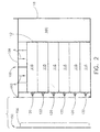
- FIGURE 2 is a side view of the battery system of Figure 1;
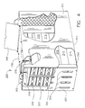
- FIGURE 3 is a front perspective view of a 6-cell battery system according to a first alternative approach;
- FIGURE 4 is a front perspective view of a 12-cell battery system according to a second alternative approach;
- FIGURE 5 is a partial cut away view illustrating the installation and operation of the compression bolt as it is used to bias the compression member against a stack of battery cells in the battery compartment;
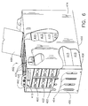
- FIGURE 6 illustrates an open top embodiment of the battery system embodying the present invention; and
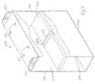
- FIGURE 7 illustrates an alternative embodiment of the present invention that includes a constraint member to address battery compartment side wall bulging.
-
- As illustrated in Figs. 1 and 2, the battery system includes a
housing 100. In accordance with a first embodiment of the present invention thehousing 100 includes abase 102 andvertical side walls 104 that together withrear wall 112 define asingle battery compartment 110. Acompression member 175 is positioned in thebattery compartment 110 below atop wall 108 and between thevertical side walls 104 for vertical movement therebetween. Thetop wall 108 includes cable openings (not shown) to permit the battery cables to be routed to the external electrical equipment powered by the battery system. -
Front cover 150 protects the battery cell terminals and includes ventopenings 154 to provide proper battery cell ventilation. Thevent openings 154 also are positioned to provide access to battery terminals 120,122 for testing.Front cover 150 further includes rails 156 (Fig. 2) that extend intobattery compartment 110 to help hold thebattery cells 115 in place. - The term "cell" as used herein refers to a single electrochemical unit including multiple positive and negative plates with separators therebetween. Each unit is assembled in a separate container or casing and is electrically connected to other cells at a point outside of the casing via the terminals.
- Referring now to the embodiment of Figure 3, the
front cover 250 is secured to the housing 200 in any suitable manner, as for example, with 4 bolts (not shown) that extend throughfront cover tabs 252 to engagenuts 262 welded to liftingear 271, and throughholes 253 to engagenuts 262 welded to the backside ofbase tabs 214. The front cover of this alternative embodiment further includesvent openings 254 andrails 256 as was discussed above. The front covers of the other embodiments are secured to the housings in a similar fashion. - Reverting to the embodiment of Figs. 1 and 2, outer
rear wall 118 is secured to extensions oftop wall 108,base 102, andside walls 104 beyond battery compartmentrear wall 112.Housing 100 includes aspace 160 between battery compartmentrear wall 112 and outerrear wall 118. This double wall arrangement is provided so that the outside dimensions of thehousing 100 match those of battery compartments used in lift trucks, pallet jacks and the like. It should be understood that, depending on the width of thecells 115, aspacer 106 may be provided inward of and parallel to thevertical walls 104 to hold the cells in place. - Referring to the alternative embodiment of the battery system illustrated in Figure 3, this embodiment includes a
battery charger compartment 264adjacent space 260. Access to the compartment is provided via hingedcover 266. Thespace 260 between thebattery compartment 210 and thebattery charger compartment 264 typically is smaller than that in the embodiment described above.Ventilation openings 219 are provided in outerrear wall 218 to provide for proper cooling of the battery charger. - This embodiment further includes a
battery compartment 210 formed by abase 202 andside walls 204. Acompression member 275 is positioned betweenside walls 204 and cooperates withcompression bolts 270 extending through top wall 208 to provide proper compression for the stack ofbattery cells 215. Aspacer 206 may be provided to perform the functions described above. Theindividual cells 215 are arranged to have alternatingbattery terminals - Each of the embodiments described above accepts six
horizontal battery cells battery compartment VRLA cells compartments cells battery compartment 110 would be chosen to be less than the uncompressed height or equal to the compressed height of the stack ofbattery cells - A preferred embodiment of the present invention addresses the need for compression by providing a means for effecting a prescribed downward pressure against the stack of lead-acid battery cells. That is, the stack of cells is treated as a single unit. One component of the means for effecting a prescribed downward pressure is the compression assembly illustrated in Figures 1, 2 and 5.
Compression plate 175 is free to move upwardly and downwardly inside thebattery compartment 110 between thevertical side walls 104. The means for effecting a prescribed downward pressure further includes a biasing mechanism for pressing the compression plate downwardly in the directions of arrows "A" (Fig. 2) against the stack of lead-acid cells 115. Any simple mechanical device capable of exerting a downward biasing force againstcompression plate 175 may be used in the practice of the present invention as a biasing mechanism. In a preferred embodiment,top cover 108 is provided with at least one and, preferably, a plurality of openings 179 (Fig. 5) through which extendcompression bolts 170. Each compression bolt engages and is pulled downwardly by internally threadedmember 172 secured to the underside oftop cover 108. The internally threadedmember 172 is aligned with theopening 171 to permit passage of thecompression bolt 170. In a preferred embodiment, internally threadedmember 172 may comprise a nut that has been welded to the underside oftop cover 108. It will be readily that a specially machined member may be used for this function in an equivalent fashion. - The number of
compression bolts 170 provided to biascompression plate 175 against the stack of lead-acid battery cells 115 may vary depending on the size of thebattery cells 115. In a preferred embodiment, four compression bolts are provided, although it is believed that, depending on battery performance, six compression bolts may be used. The number ofcompression bolts 170 used should be chosen to ensure thatcompression plate 175 remains substantially flat along the length of the top battery cell in the stack. In a preferred embodiment, the top cover may be provided with a plurality of openings and associated internally threaded members so that compression bolts may be installed as needed to provide proper compression depending on the size and number of cells in the stack. - It will be readily appreciated that there are other alternatives for providing a threaded engagement for the
compression bolts 170. By way of non-limiting example, the opening 179 (Fig. 5) in thetop cover 108 could be internally threaded thereby eliminating the need for threadedmember 172. Alternatively, theopening 179 could be fitted with an internally threaded bushing (not shown) for threaded engagement with thecompression bolt 170. - Desirably,
compression member 175 is sized so as to have substantially the same surface area as that of the top surface of the battery cell stack. Clearance should be provided between the compression member and the battery compartment walls so that the compression member will move downwardly without binding againstside walls 104. In a preferred embodiment, a space of between about 1.5 and 3.2mm (0.06 and 0.125 inches) is provided between the edge ofcompression member 175 andvertical side walls 104. Other clearance dimensions may be used provided that sufficient room is provided betweenside walls 104 for uninterrupted vertical movement by the compression member even if, during such movement, there is contact between thecompression member 175 andside walls 104. With respect to other physical characteristics, thecompression member 175 must have sufficient thickness and strength to carry the loads associated with proper compression without deformation. Although thecompression member 175 is shown constructed as a one-piece construction, the scope of the present invention includes using a multiple-piece construction as needed. - The length of the
compression bolts 170 should be selected such that, when the bolts are fully extended through internal threadedmember 172, the bolt head contactstop cover 108. When properly positioned, thebolt 170 will have an exposed length extending belowtop cover 108. This exposed length should exceed the distance between the top surface of thecompression member 175 and the underside oftop wall 108 as measured for an uncompressed stack ofbattery cells 115. This desired exposed length helps to ensure that compression may be effected. A lock washer (not shown) may be provided between the bolt head andtop cover 108 to prevent the bolts from loosening due to vibration. - As stated above, the means for applying positive pressure to the stack of
battery cells compression member 175 andtop cover 108. The spring constant of the springs would be selected to provide appropriate compression. Alternatively, a lever-operated cam assembly could be provided above compression member. The advantage of this approach is that thecompression member 175 may be secured into position quickly. Yet another approach would use hydraulic or pneumatic cylinders in the space between thecompression member 175 andtop cover 108. Two other approaches include using an inflatable bladder or a scissors-type mechanism similar to a car jack. Alternatively, thetop cover 108 could be hingedly attached to the outerrear wall 118 so as to be rotatable into a closed position atop the stack of cells. One particularly simple approach is to increase the weight of compression member until it exerts a sufficient downward force to provide proper compression for the stack of batteries. The advantages of this approach include: 1) the elimination of any need for maintenance on the biasing mechanism; 2) the requirement for only one part to provide compression; and 3) the ability to vary the amount of compression easily by varying the size of a single compression member. Alternatively, a plurality of compression members of different weights may be combined as needed to achieve a particular amount of downward force. It will be readily understood that the top wall and thecompression plate 175 would be a single piece in this approach. The scope of the present invention includes these and any other equivalent structure as those equivalents would be understood by one of ordinary skill. - It should be recognized that sizing the
battery compartment 110 to have a vertical height dimension equal to the compressed height of the stack ofbattery cells 115 is itself one form of a means for effecting a prescribed downward pressure against the stack ofbattery cells 115. - The battery systems embodying the present invention provide many advantages over prior art approaches. As an example, the shelfless housing is more economical to manufacture, and facilitates loading of the
individual cells 115. In the latter respect, the housing is rotated about its bottom rear edge 90 degrees so that it rests on the outerrear wall 118. The opening of thebattery compartment 110 then points upwardly. Individual battery cells are inserted into the housing one by one until the desired number of cells has been installed.Compression member 175 is placed in thebattery compartment 110 against the uncompressed cell stack. Preferably, thecompression bolts 170 are inserted and tightened while the housing is resting on outerrear wall 118. Thus, when the housing is rotated to rest on tray base the cells are already properly compressed. The systems embodying the present invention provide other advantages that will be readily apparent to one of ordinary skill but that are not mentioned herein. Moreover, the systems provides solutions to problems that may not be mentioned here, but that will be recognized by one of ordinary skill. - Although the preferred embodiments depicted in the Figures 1-3 each show a single stack of
battery cells cell tray assembly 300 are shown in Figures 4 and 6. As seen in Fig. 4, this embodiment includes abase 302,vertical'side walls 304 andtop wall 308. Thebattery compartment 310 in this embodiment is sized to accommodate two side-by-side stacks of sixbattery cells 315 having terminals 320,322.Compression member 375 is positioned betweenvertical side walls 304 to provide proper compression for thebattery cells 315. Although this embodiment is shown provided with sixcompression bolts 370,additional compression bolts 370 may be provided as needed to ensure proper battery cell performance.Front cover 350 is provided with an appropriate number ofvent openings 354 to accommodate theadditional battery cells 315.Front cover 350 further includesrails 356 that have the same configuration and that serve the same function as was the case with the embodiments discussed above. Thefront cover 350 is secured to thehousing 300 using, weldednuts 362 in a similar fashion to that described above. This embodiment may include a battery charger compartment provided with a hingedcover 366 as was discussed above. It will be readily appreciated that other numbers and sizes of battery cells may be accommodated by varying the size of the battery compartment and the compression member as needed. For example, 18, 24, 36 or more cells may be accommodated by increasing the size of the shelfless housing as needed. - Referring now to Fig. 6, an
alternative embodiment 400 having an open top is illustrated. This embodiment includes abase 402,side walls 404, abattery compartment 410 and a hingedcover 466. The two stacks ofcells 415 are arranged side-by-side with alternating terminals 420,422.Front cover 450 includesvent openings 454 andrails 456 and is secured tohousing 400 using bolts (not shown) and nuts 462. - In this embodiment the
top cover 108 is eliminated completely. At least onecross beam 425 would be mounted on theside walls 404 so as to span the gap therebetween. The cross beams 425 would be provided with threaded openings or some type of threaded member for receiving thecompression bolts 170. This approach could be incorporated in any of the embodiments illustrated in the Figures and offers weight savings as a solid top is not provided on thehousing 400. - Referring now to Figure 7, in certain housing configurations having a relatively large battery compartment vertical dimension, it may be necessary to take steps to prevent the
side walls 504 from bulging outwardly after the stack of battery cells has been compressed. One approach to address this bulging is to increase the thickness of theside walls 504. That approach, while potentially successful, does require additional expense and tends to increase the overall width and weight of the battery assembly. An alternative approach is to constrain the side walls so as to hold them in a substantially vertical position. Figure 7 is an isometric, partial cutaway view of ahousing 500 illustrating a sidewall constraint member 513 that may comprise a flat bar, rod, strap or equivalent structure attached to eachside wall 504 and spanning the width of thebattery compartment 510. The constraint member is secured at each end to theside walls 504. Used alone, theconstraint member 513 would contact the cells directly above and below it. The compressive force applied to the stack of battery cells could cause theconstraint member 513 to generate unacceptable point loading on those cells. Accordingly, a floatingplate 515 is positioned betweenside walls 504 and extends underneath theconstraint member 513 to prevent theconstraint member 513 from making direct contact with the cells immediately above and below theconstraint member 513. The floatingplate 515 is not attached to theside walls 504 or to therear wall 512. Thus, it is free to move vertically as the battery cells are compressed. In order to conserve space within thebattery compartment 510 theconstraint member 513 is positioned in arecess 514 in the floatingplate 515. The depth of therecess 514 should be selected such that, when the stack of battery cells is compressed fully, the top surface of the floatingplate 515 is above the top surface of theconstraint member 513. The floatingplate 515 may be constructed of metal or, more preferably, from a thermoplastic material to conserve weight. Because the floatingplate 515 is substantially non-load bearing, its thickness need be only that necessary to protect the battery cell immediately below it from potential point loading by theconstraint member 513. - The
constraint member 513 desirably is constructed from metal. Alternatively, a fabric strap constructed using well known high strength fibers may be used. Non-limiting examples of such fibers include aramids such as that sold under the Kevlar® brand and ultra high molecular weight polyethylenes such as that sold under the Spectra® brand. Straps constructed from these materials can have strength values similar to those of metals and can provide weight savings. - Although Figure 7 shows a single constraint member, it will be readily appreciated that two or more constraint members may be used depending on the extent of the bulging expected. The vertical positioning of the constraint members may be varied within the
battery compartment 510 betweenbase 502 and top cover 508 as needed. Desirably, the constraint members would be positioned near the point of the greatest amount of bulging. - This constraint member and floating plate arrangement is not intended to act as a shelf for dividing the battery compartment into multiple compartments. Rather, the function of this arrangement is to reinforce the walls of the housing. The constraint member is positioned such that it is not supporting the weight of the cells above it. In this manner, the cell stack is still treated as a single unit. The need for a side wall constraint will vary depending on the number of cells in the stack and the thickness of the side walls. Making the determination to include a constraint is within the ability of one of ordinary skill. It will be readily appreciated that a combination of increasing wall thickness and providing a constraint member may be used to address side wall bulging. The scope of the present invention includes using other structures and means for reinforcing the walls of the housing to prevent bulging.
- It will be appreciated that, in each of the embodiments described above, the
individual cells - Although the present invention has been described with preferred embodiments, it is to be understood that modifications and variations may be utilized without departing from the scope of this invention as defined in the appended claims.
Claims (18)
- A battery system for battery powered vehicles comprising:a. a shelfless battery compartment having a base, a top, a pair of side walls and a rear wall;b. at least one stack of separately cased, valve-regulated lead-acid battery cells so positioned in said compartment that the plates thereof are horizontally oriented; andc. a means for effecting a prescribed downward pressure against said stack of battery cells.
- The battery system according to claim 1, wherein said means for effecting a prescribed downward pressure comprises said shelfless compartment having a vertical dimension less than the uncompressed height of said stack of valve-regulated lead-acid battery cells.
- The battery system according to claim 1, wherein said means for effecting downward pressure against said stack of battery cells comprises a compression assembly including a compression plate positioned in said battery compartment atop said stack of battery cells and a biasing mechanism for pressing the compression plate downwardly.
- The battery system according to claim 3, wherein the biasing mechanism comprises:i. at least one threaded opening in the top of said battery compartment; andii. at least one threaded compression bolt extending through the battery compartment opening so as to exert a biasing force against the compression plate.
- A shelfless housing for receiving one or more stacks of lead acid cells in a battery assembly for battery powered vehicles, said housing comprising:a. a base;b. vertical side walls and a rear wall attached to the base, and a top, wherein the housing base, vertical side walls, rear wall and top define a shelfless battery compartment; andc. a compression member of size and shape as to be positionable in the battery compartment between the side walls for vertical movement between the top and said cells when positioned therein, so as to compress said stack of battery cells stacked in a horizontal position in the battery compartment.
- The housing according to claim 5, further comprising a means for effecting downward pressure against said compression member and thereby against said stack of battery cells.
- The housing according to claim 5 or 6, further comprising:i. at least one threaded opening in said top, andii. at least one threaded compression bolt extending through the top opening and contacting the compression member while threadedly engaging at least one threaded opening.
- The housing according to claim 7, further comprising between about four and about six compression bolts extending through the top and biasing the compression member against the stack of battery cells.
- A shelfless housing for receiving one or more stacks of lead acid cells in a battery assembly for battery powered vehicles, said housing comprising:a. a base;b. vertical side walls attached to the base; andc. a compression member positionable between the side walls for vertical movement therebetween, wherein the housing base, vertical side walls, and the compression member define a single variable-sized battery compartment for receiving a stack of separately cased battery cells stacked in a horizontal position.
- The housing according to claim 9, further comprising a biasing mechanism for pressing the compression member downwardly against the stack of battery cells.
- The housing according to claim 10, wherein the biasing mechanism comprises:a. at least one cross beam mounted between the vertical side walls, the cross beam including at least one threaded opening;b. at least one threaded compression bolt extending through the threaded opening so as to exert a biasing force against the compression member.
- A shelfless housing for receiving one or more stacks of lead acid cells in a battery assembly for battery powered vehicles, said housing comprising:a. a base;b. vertical side walls and a rear wall attached to the base, andc. a top wall, wherein the housing base, vertical side walls, rear wall and top wall define a shelfless battery compartment having a vertical dimension between said top wall and said base less than the uncompressed height of said one or more stacks of separately cased lead-acid battery cells.
- The system according to any of claims 1 to 4, or housing according to any of claims 5 to 12 further comprising a constraint member for maintaining the side walls in a substantially vertical position.
- The system or housing according to claim 13, wherein the constraint member is attached to each side wall so as to span the width of the shelfless battery compartment.
- The system or housing according to any preceding claim, wherein the battery compartment is sized to accept a single stack of up to about 12 battery cells.
- The system or housing according to any of claims 1 to 14, wherein the battery compartment is sized to accept at least two side-by-side stacks of up to about 12 battery cells.
- The system or housing according to any preceding claim, further comprising a battery charger compartment defined by horizontal extensions of the base and the vertical side walls, wherein the compartment further includes a battery charger compartment rear wall attached to the wall extensions and having a ventilation panel.
- The system or housing according to claim 17, further comprising a battery charger compartment cover hingedly connected to the top of the compartment.
Applications Claiming Priority (2)
| Application Number | Priority Date | Filing Date | Title |
|---|---|---|---|
| US09/157,478 US6162559A (en) | 1998-09-21 | 1998-09-21 | Compressed battery system for motive power applications |
| US157478 | 1998-09-21 |
Publications (2)
| Publication Number | Publication Date |
|---|---|
| EP0989618A1 true EP0989618A1 (en) | 2000-03-29 |
| EP0989618B1 EP0989618B1 (en) | 2003-03-05 |
Family
ID=22563913
Family Applications (1)
| Application Number | Title | Priority Date | Filing Date |
|---|---|---|---|
| EP19990307369 Expired - Lifetime EP0989618B1 (en) | 1998-09-21 | 1999-09-16 | A battery housing and system for motive power applications |
Country Status (8)
| Country | Link |
|---|---|
| US (1) | US6162559A (en) |
| EP (1) | EP0989618B1 (en) |
| AT (1) | ATE233949T1 (en) |
| AU (1) | AU745318B2 (en) |
| CA (1) | CA2285977C (en) |
| DE (1) | DE69905672T2 (en) |
| NZ (1) | NZ504576A (en) |
| WO (1) | WO2000017947A1 (en) |
Cited By (7)
| Publication number | Priority date | Publication date | Assignee | Title |
|---|---|---|---|---|
| US6862801B2 (en) | 2001-11-30 | 2005-03-08 | Ballard Power Systems Inc. | Systems, apparatus and methods for isolating, compressing and/or retaining the structure of a fuel cell stack |
| EP2018989A1 (en) * | 2007-07-25 | 2009-01-28 | Linde Material Handling GmbH | Jack lift with a battery compartment and a battery |
| EP2381506A1 (en) * | 2010-04-21 | 2011-10-26 | SB LiMotive Co., Ltd. | Battery module |
| WO2013070593A1 (en) * | 2011-11-07 | 2013-05-16 | Johnson Controls Technology Llc | One-piece housing with plugs for prismatic cell assembly |
| FR2990062A1 (en) * | 2012-04-30 | 2013-11-01 | Batscap Sa | ENERGY STORAGE MODULE COMPRISING MOVING MEANS FOR MOVING A PLURALITY OF ENERGY STORAGE ELEMENTS |
| CN111630684A (en) * | 2018-01-17 | 2020-09-04 | 斯托克林物流股份有限公司 | Battery power for industrial trucks in potentially explosive areas |
| CN112968244A (en) * | 2021-02-02 | 2021-06-15 | 苏通新材无锡有限公司 | New forms of energy electric automobile lithium cell aluminium alloy shell |
Families Citing this family (29)
| Publication number | Priority date | Publication date | Assignee | Title |
|---|---|---|---|---|
| US6641951B1 (en) * | 1998-09-21 | 2003-11-04 | Douglas Battery Manufacturing Company | Battery cell tray assembly and sytem |
| US6410185B1 (en) * | 1999-02-15 | 2002-06-25 | Sony Corporation | Battery device for loading on moving body |
| FR2790870B1 (en) * | 1999-03-11 | 2001-06-01 | Oldham France Sa | BOX FOR ELECTRICAL BATTERY ASSEMBLY |
| KR100337887B1 (en) * | 2000-06-14 | 2002-05-24 | 김순택 | Charge and discharge system of battery |
| US6719150B2 (en) * | 2001-05-30 | 2004-04-13 | Kim Manufacturing Company | Battery rack and system |
| US20030003350A1 (en) * | 2001-07-02 | 2003-01-02 | C&D Charter Holdings, Inc. | Horizontal tray insert and tray assembly for motive-power applications |
| US6780540B2 (en) | 2001-08-08 | 2004-08-24 | Delphi Technologies, Inc. | Element sleeve for a battery |
| US7740142B2 (en) * | 2001-11-20 | 2010-06-22 | Concorde Battery Corporation | Battery construction for mounting a shelved rack |
| US7791347B2 (en) | 2003-11-18 | 2010-09-07 | Teledyne Technologies Incorporated | Battery assembly with enhanced properties |
| US7548429B2 (en) * | 2004-06-18 | 2009-06-16 | Douglas Battery Manufacturing Company | Battery storage system |
| US20050281002A1 (en) * | 2004-06-18 | 2005-12-22 | Miller Russell L | Battery storage system |
| KR100948970B1 (en) * | 2006-03-13 | 2010-03-23 | 주식회사 엘지화학 | Medium and large battery module with shock absorbing member |
| US8465863B2 (en) * | 2008-04-09 | 2013-06-18 | GM Global Technology Operations LLC | Batteries and components thereof and methods of making and assembling the same |
| US8845762B2 (en) * | 2008-04-09 | 2014-09-30 | GM Global Technology Operations LLC | Batteries and components thereof and methods of making and assembling the same |
| CH703973A1 (en) * | 2010-10-29 | 2012-04-30 | Obrist Engineering Gmbh | Temperature-controlled battery. |
| US20130022853A1 (en) * | 2011-07-20 | 2013-01-24 | Robb Protheroe | Modular Variable Compression Thermal Management Battery Retaining System |
| US8652672B2 (en) * | 2012-03-15 | 2014-02-18 | Aquion Energy, Inc. | Large format electrochemical energy storage device housing and module |
| DE102013001467B4 (en) | 2013-01-29 | 2021-12-09 | Audi Ag | Pressing device, method for operating a pressing device and method for manufacturing a battery |
| WO2017035257A1 (en) * | 2015-08-24 | 2017-03-02 | The Regents Of The University Of California | All-iron redox flow battery tailored for off-grid portable applications |
| JP7203080B2 (en) | 2017-07-13 | 2023-01-12 | イーコントロールズ エルエルシー | Modular lithium-ion battery system for forklifts |
| WO2019146238A1 (en) * | 2018-01-25 | 2019-08-01 | 三洋電機株式会社 | Power supply device, vehicle provided with power supply device, and power storage device |
| US12266953B1 (en) | 2020-08-17 | 2025-04-01 | Econtrols, Llc | Dual chemistry rechargeable battery system for use in electric APU-equipped commercial trucks |
| WO2022256730A1 (en) | 2021-06-04 | 2022-12-08 | Econtrols, Llc | Lithium-ion battery charging system for fork lifts |
| EP4156368A1 (en) | 2021-09-24 | 2023-03-29 | HOPPECKE Batterien GmbH & Co. KG. | System comprising a stacking aid and a plurality of agm batteries |
| DE102022123512A1 (en) | 2022-09-14 | 2024-03-14 | Hoppecke Batterien Gmbh & Co. Kg | Battery, in particular AGM battery and system consisting of a stacking aid and a plurality of AGM batteries |
| EP4340109B1 (en) | 2022-09-14 | 2025-10-01 | HOPPECKE Batterien GmbH & Co. KG. | System consisting of a stacking aid and a plurality of agm batteries |
| DE102022123511A1 (en) | 2022-09-14 | 2024-03-14 | Hoppecke Batterien Gmbh & Co. Kg | System consisting of a stacking aid and a plurality of AGM batteries |
| DE102022123510A1 (en) | 2022-09-14 | 2024-03-14 | Hoppecke Batterien Gmbh & Co. Kg | System consisting of a stacking aid and a plurality of AGM batteries |
| DE102022123509A1 (en) | 2022-09-14 | 2024-03-14 | Hoppecke Batterien Gmbh & Co. Kg | System consisting of a stacking aid and a plurality of AGM batteries |
Citations (4)
| Publication number | Priority date | Publication date | Assignee | Title |
|---|---|---|---|---|
| JPH04282555A (en) * | 1991-03-11 | 1992-10-07 | Nec Corp | Battery storing structure |
| US5409787A (en) * | 1993-02-17 | 1995-04-25 | Electrosource, Inc. | Battery plate compression cage assembly |
| EP0662725A1 (en) * | 1994-01-06 | 1995-07-12 | Gnb Industrial Battery Company | Sealed lead-acid battery tray assemblies and motive power vehicles using such battery tray assemblies |
| US5441123A (en) * | 1993-04-01 | 1995-08-15 | Gnb Battery Technologies Inc. | Sealed lead-acid cell tray assembly and motive powered vehicle using such cell tray assembly |
Family Cites Families (32)
| Publication number | Priority date | Publication date | Assignee | Title |
|---|---|---|---|---|
| US23644A (en) * | 1859-04-12 | Improvement in machines for cutting cornstalks | ||
| USRE23644E (en) | 1945-03-14 | 1953-04-14 | Battery separator | |
| US2956100A (en) * | 1955-10-12 | 1960-10-11 | Yardney International Corp | Electric battery structure |
| US4029855A (en) * | 1975-12-10 | 1977-06-14 | Globe-Union Inc. | Storage battery and method of making the same |
| US4074423A (en) * | 1976-01-27 | 1978-02-21 | General Battery Corporation | System and apparatus for assembling industrial lead-acid storage batteries |
| JPS5445755A (en) * | 1977-09-19 | 1979-04-11 | Yuasa Battery Co Ltd | Separator for storage battery |
| US4383011A (en) * | 1980-12-29 | 1983-05-10 | The Gates Rubber Company | Multicell recombining lead-acid battery |
| US4425412A (en) * | 1982-05-26 | 1984-01-10 | Eagle-Picher Industries, Inc. | Lead/acid battery having horizontal plates |
| GB2129192B (en) * | 1982-10-29 | 1985-10-16 | Chloride Group Plc | Manufacturing recombination electric storage cells |
| PT77569B (en) * | 1982-10-29 | 1986-03-12 | Chloride Group Plc | Multicell electric storage batteries |
| GB2150343B (en) * | 1983-11-29 | 1986-09-17 | Chloride Group Plc | Lead acid recombination cells |
| JPS60189861A (en) * | 1984-03-12 | 1985-09-27 | Nippon Muki Kk | Separator for sealed type lead storage battery and sealed type lead storage battery |
| US4652505A (en) * | 1984-03-29 | 1987-03-24 | Shin-Kobe Machinery Co., Ltd. | Sealed lead storage battery |
| SE454828B (en) * | 1984-05-07 | 1988-05-30 | Erik Sundberg | END BLYACKUMULATOR WITH ELECTROLYTE RESERVE |
| GB2160701B (en) * | 1984-06-22 | 1988-02-24 | Chloride Group Plc | Separators for recombination electric storage cells |
| US4713304A (en) * | 1986-06-18 | 1987-12-15 | Gnb Incorporated | Method of preparing lead-acid battery plates and lead-acid batteries containing plates so prepared |
| DE3622492C2 (en) * | 1986-07-02 | 1996-07-18 | Hagen Batterie Ag | Lead accumulator, the positive electrode plates of which are pocketed in separator pockets that are open at the top |
| US4743270A (en) * | 1987-05-27 | 1988-05-10 | General Motors Corporation | Filling mat-immobilized-electrolyte batteries |
| JP2545878B2 (en) * | 1987-06-26 | 1996-10-23 | 住友化学工業株式会社 | Lead acid battery |
| US4780379A (en) * | 1987-10-06 | 1988-10-25 | Gates Energy Products, Inc. | Multicell recombinant lead-acid battery with vibration resistant intercell connector |
| US5091275A (en) * | 1990-04-25 | 1992-02-25 | Evanite Fiber Corporation | Glass fiber separator and method of making |
| US5250372A (en) * | 1991-08-21 | 1993-10-05 | General Motors Corporation | Separator for mat-immobilized-electrolyte battery |
| US5851695A (en) * | 1992-02-10 | 1998-12-22 | C & D Technologies, Inc. | Recombinant lead-acid cell and long life battery |
| US5336275A (en) * | 1992-05-11 | 1994-08-09 | Hollingsworth & Vose Company | Method for assembling battery cells containing pre-compressed glass fiber separators |
| US5366827A (en) * | 1992-06-10 | 1994-11-22 | Digital Equipment Corporation | Modular housing for batteries and battery charger |
| US5376477A (en) * | 1992-11-10 | 1994-12-27 | Teledyne Industries, Inc. | Storage battery and plate separator systems for a storage battery |
| US5384211A (en) * | 1993-09-27 | 1995-01-24 | W. R. Grace & Co.-Conn. | Oxidation resistant enveloped separator |
| US5512065A (en) * | 1993-10-12 | 1996-04-30 | Gnb Battery Technologies Inc. | Methods for assembling lead-acid batteries |
| US5401279A (en) * | 1993-12-27 | 1995-03-28 | General Motors Corporation | Filling mat-immobilized-electrolyte batteries |
| US5441126A (en) * | 1994-02-25 | 1995-08-15 | Orrick; James | Ladder guard |
| JPH08203539A (en) * | 1994-12-13 | 1996-08-09 | Pioneer Electron Corp | Laminated type battery |
| US5731099A (en) * | 1996-09-27 | 1998-03-24 | Jbi Corporation | Apparatus for charging a controlled volume of an electrolyte to battery case |
-
1998
- 1998-09-21 US US09/157,478 patent/US6162559A/en not_active Expired - Lifetime
-
1999
- 1999-02-17 AU AU26841/99A patent/AU745318B2/en not_active Ceased
- 1999-02-17 NZ NZ504576A patent/NZ504576A/en unknown
- 1999-02-17 WO PCT/US1999/003362 patent/WO2000017947A1/en not_active Ceased
- 1999-02-17 CA CA002285977A patent/CA2285977C/en not_active Expired - Fee Related
- 1999-09-16 DE DE69905672T patent/DE69905672T2/en not_active Expired - Fee Related
- 1999-09-16 AT AT99307369T patent/ATE233949T1/en not_active IP Right Cessation
- 1999-09-16 EP EP19990307369 patent/EP0989618B1/en not_active Expired - Lifetime
Patent Citations (4)
| Publication number | Priority date | Publication date | Assignee | Title |
|---|---|---|---|---|
| JPH04282555A (en) * | 1991-03-11 | 1992-10-07 | Nec Corp | Battery storing structure |
| US5409787A (en) * | 1993-02-17 | 1995-04-25 | Electrosource, Inc. | Battery plate compression cage assembly |
| US5441123A (en) * | 1993-04-01 | 1995-08-15 | Gnb Battery Technologies Inc. | Sealed lead-acid cell tray assembly and motive powered vehicle using such cell tray assembly |
| EP0662725A1 (en) * | 1994-01-06 | 1995-07-12 | Gnb Industrial Battery Company | Sealed lead-acid battery tray assemblies and motive power vehicles using such battery tray assemblies |
Non-Patent Citations (1)
| Title |
|---|
| PATENT ABSTRACTS OF JAPAN vol. 017, no. 089 (E - 1323) 22 February 1993 (1993-02-22) * |
Cited By (15)
| Publication number | Priority date | Publication date | Assignee | Title |
|---|---|---|---|---|
| US6862801B2 (en) | 2001-11-30 | 2005-03-08 | Ballard Power Systems Inc. | Systems, apparatus and methods for isolating, compressing and/or retaining the structure of a fuel cell stack |
| EP2018989A1 (en) * | 2007-07-25 | 2009-01-28 | Linde Material Handling GmbH | Jack lift with a battery compartment and a battery |
| EP2381506A1 (en) * | 2010-04-21 | 2011-10-26 | SB LiMotive Co., Ltd. | Battery module |
| US8465866B2 (en) | 2010-04-21 | 2013-06-18 | Samsung Sdi Co., Ltd. | Battery module including a pressure control unit |
| WO2013070593A1 (en) * | 2011-11-07 | 2013-05-16 | Johnson Controls Technology Llc | One-piece housing with plugs for prismatic cell assembly |
| CN103999258A (en) * | 2011-11-07 | 2014-08-20 | 约翰逊控制技术有限责任公司 | Integral housing with plugs for prismatic battery packs |
| WO2013164335A1 (en) * | 2012-04-30 | 2013-11-07 | Blue Solutions | Power storage module including movable means for setting a plurality of power storage elements |
| WO2013164157A1 (en) * | 2012-04-30 | 2013-11-07 | Blue Solutions | Energy storage module containing a plurality of energy storage elements and improved means of thermal dissipation and method of assembly |
| FR2990062A1 (en) * | 2012-04-30 | 2013-11-01 | Batscap Sa | ENERGY STORAGE MODULE COMPRISING MOVING MEANS FOR MOVING A PLURALITY OF ENERGY STORAGE ELEMENTS |
| CN104272496A (en) * | 2012-04-30 | 2015-01-07 | 布鲁技术公司 | Power storage module including movable means for setting a plurality of power storage elements |
| CN104272496B (en) * | 2012-04-30 | 2017-03-29 | 布鲁技术公司 | Including the energy storage module of the movable fixture for arranging multiple energy storage components |
| US9786875B2 (en) | 2012-04-30 | 2017-10-10 | Blue Solutions | Power storage module including movable means for setting a plurality of power storage elements |
| US9929384B2 (en) | 2012-04-30 | 2018-03-27 | Blue Solutions | Energy storage module containing a plurality of energy storage elements and improved means of thermal dissipation and method of assembly |
| CN111630684A (en) * | 2018-01-17 | 2020-09-04 | 斯托克林物流股份有限公司 | Battery power for industrial trucks in potentially explosive areas |
| CN112968244A (en) * | 2021-02-02 | 2021-06-15 | 苏通新材无锡有限公司 | New forms of energy electric automobile lithium cell aluminium alloy shell |
Also Published As
| Publication number | Publication date |
|---|---|
| CA2285977C (en) | 2003-12-02 |
| CA2285977A1 (en) | 2000-03-21 |
| WO2000017947A1 (en) | 2000-03-30 |
| DE69905672D1 (en) | 2003-04-10 |
| AU2684199A (en) | 2000-04-10 |
| US6162559A (en) | 2000-12-19 |
| AU745318B2 (en) | 2002-03-21 |
| EP0989618B1 (en) | 2003-03-05 |
| ATE233949T1 (en) | 2003-03-15 |
| DE69905672T2 (en) | 2003-12-18 |
| NZ504576A (en) | 2002-02-01 |
Similar Documents
| Publication | Publication Date | Title |
|---|---|---|
| US6162559A (en) | Compressed battery system for motive power applications | |
| US6641951B1 (en) | Battery cell tray assembly and sytem | |
| US5409787A (en) | Battery plate compression cage assembly | |
| KR102891400B1 (en) | Power battery packs and electric vehicles | |
| EP1225651B1 (en) | Electric accumulator battery | |
| CA2661100A1 (en) | Electrochemical cell for hybrid electric vehicle applications | |
| KR20020008128A (en) | Battery with container compartment and end wall stiffening block | |
| US6153335A (en) | Battery cell construction including fiberous mat separator | |
| US3846175A (en) | Storage battery | |
| US6458484B2 (en) | Fiber-structure electrode system for nickel-cadmium batteries and procedure for its manufacture | |
| JP2003508878A (en) | Low profile front terminal lead storage battery | |
| GB2042242A (en) | Charging and discharging lead- acid batteries | |
| US20060216595A1 (en) | Battery assembly having improved lug profile | |
| RU216581U1 (en) | BATTERY WITH BATTERY CELL PRESS DEVICE | |
| CN220086228U (en) | Lithium battery pack | |
| US6235421B1 (en) | Enclosed lead storage battery | |
| RU16804U1 (en) | DEVICE FOR PLACING A BATTERY BLOCK | |
| EP0207742A2 (en) | Multicell recombination electric storage batteries | |
| KR20250154129A (en) | Tray for activating of battery cell and battery cell produced using the same, and battery pack and vehicle comprising battery cells | |
| KR20250084737A (en) | Battery pack and apparatus for manufacturing battery pack | |
| KR20250144714A (en) | Battery pack | |
| KR20240038607A (en) | Battery pack case and battery pack comprising the same | |
| JP2003051288A (en) | Battery case for lead-acid battery |
Legal Events
| Date | Code | Title | Description |
|---|---|---|---|
| PUAI | Public reference made under article 153(3) epc to a published international application that has entered the european phase |
Free format text: ORIGINAL CODE: 0009012 |
|
| 17P | Request for examination filed |
Effective date: 19991004 |
|
| AK | Designated contracting states |
Kind code of ref document: A1 Designated state(s): AT BE CH CY DE DK ES FI FR GB GR IE IT LI LU MC NL PT SE |
|
| AX | Request for extension of the european patent |
Free format text: AL;LT;LV;MK;RO;SI |
|
| AKX | Designation fees paid |
Free format text: AT BE CH CY DE DK ES FI FR GB GR IE IT LI LU MC NL PT SE |
|
| 17Q | First examination report despatched |
Effective date: 20010124 |
|
| GRAH | Despatch of communication of intention to grant a patent |
Free format text: ORIGINAL CODE: EPIDOS IGRA |
|
| GRAH | Despatch of communication of intention to grant a patent |
Free format text: ORIGINAL CODE: EPIDOS IGRA |
|
| GRAA | (expected) grant |
Free format text: ORIGINAL CODE: 0009210 |
|
| AK | Designated contracting states |
Designated state(s): AT BE CH CY DE DK ES FI FR GB GR IE IT LI LU MC NL PT SE |
|
| PG25 | Lapsed in a contracting state [announced via postgrant information from national office to epo] |
Ref country code: NL Free format text: LAPSE BECAUSE OF FAILURE TO SUBMIT A TRANSLATION OF THE DESCRIPTION OR TO PAY THE FEE WITHIN THE PRESCRIBED TIME-LIMIT Effective date: 20030305 Ref country code: LI Free format text: LAPSE BECAUSE OF FAILURE TO SUBMIT A TRANSLATION OF THE DESCRIPTION OR TO PAY THE FEE WITHIN THE PRESCRIBED TIME-LIMIT Effective date: 20030305 Ref country code: IT Free format text: LAPSE BECAUSE OF FAILURE TO SUBMIT A TRANSLATION OF THE DESCRIPTION OR TO PAY THE FEE WITHIN THE PRESCRIBED TIME-LIMIT;WARNING: LAPSES OF ITALIAN PATENTS WITH EFFECTIVE DATE BEFORE 2007 MAY HAVE OCCURRED AT ANY TIME BEFORE 2007. THE CORRECT EFFECTIVE DATE MAY BE DIFFERENT FROM THE ONE RECORDED. Effective date: 20030305 Ref country code: GR Free format text: LAPSE BECAUSE OF FAILURE TO SUBMIT A TRANSLATION OF THE DESCRIPTION OR TO PAY THE FEE WITHIN THE PRESCRIBED TIME-LIMIT Effective date: 20030305 Ref country code: FI Free format text: LAPSE BECAUSE OF FAILURE TO SUBMIT A TRANSLATION OF THE DESCRIPTION OR TO PAY THE FEE WITHIN THE PRESCRIBED TIME-LIMIT Effective date: 20030305 Ref country code: CH Free format text: LAPSE BECAUSE OF FAILURE TO SUBMIT A TRANSLATION OF THE DESCRIPTION OR TO PAY THE FEE WITHIN THE PRESCRIBED TIME-LIMIT Effective date: 20030305 Ref country code: BE Free format text: LAPSE BECAUSE OF FAILURE TO SUBMIT A TRANSLATION OF THE DESCRIPTION OR TO PAY THE FEE WITHIN THE PRESCRIBED TIME-LIMIT Effective date: 20030305 Ref country code: AT Free format text: LAPSE BECAUSE OF FAILURE TO SUBMIT A TRANSLATION OF THE DESCRIPTION OR TO PAY THE FEE WITHIN THE PRESCRIBED TIME-LIMIT Effective date: 20030305 |
|
| REG | Reference to a national code |
Ref country code: GB Ref legal event code: FG4D |
|
| REG | Reference to a national code |
Ref country code: CH Ref legal event code: EP |
|
| REG | Reference to a national code |
Ref country code: IE Ref legal event code: FG4D |
|
| REF | Corresponds to: |
Ref document number: 69905672 Country of ref document: DE Date of ref document: 20030410 Kind code of ref document: P |
|
| PG25 | Lapsed in a contracting state [announced via postgrant information from national office to epo] |
Ref country code: SE Free format text: LAPSE BECAUSE OF FAILURE TO SUBMIT A TRANSLATION OF THE DESCRIPTION OR TO PAY THE FEE WITHIN THE PRESCRIBED TIME-LIMIT Effective date: 20030605 Ref country code: PT Free format text: LAPSE BECAUSE OF FAILURE TO SUBMIT A TRANSLATION OF THE DESCRIPTION OR TO PAY THE FEE WITHIN THE PRESCRIBED TIME-LIMIT Effective date: 20030605 Ref country code: DK Free format text: LAPSE BECAUSE OF FAILURE TO SUBMIT A TRANSLATION OF THE DESCRIPTION OR TO PAY THE FEE WITHIN THE PRESCRIBED TIME-LIMIT Effective date: 20030605 |
|
| NLV1 | Nl: lapsed or annulled due to failure to fulfill the requirements of art. 29p and 29m of the patents act | ||
| PGFP | Annual fee paid to national office [announced via postgrant information from national office to epo] |
Ref country code: GB Payment date: 20030901 Year of fee payment: 5 |
|
| REG | Reference to a national code |
Ref country code: CH Ref legal event code: PL |
|
| PG25 | Lapsed in a contracting state [announced via postgrant information from national office to epo] |
Ref country code: LU Free format text: LAPSE BECAUSE OF NON-PAYMENT OF DUE FEES Effective date: 20030916 Ref country code: IE Free format text: LAPSE BECAUSE OF NON-PAYMENT OF DUE FEES Effective date: 20030916 Ref country code: CY Free format text: LAPSE BECAUSE OF FAILURE TO SUBMIT A TRANSLATION OF THE DESCRIPTION OR TO PAY THE FEE WITHIN THE PRESCRIBED TIME-LIMIT Effective date: 20030916 |
|
| PGFP | Annual fee paid to national office [announced via postgrant information from national office to epo] |
Ref country code: FR Payment date: 20030918 Year of fee payment: 5 |
|
| PG25 | Lapsed in a contracting state [announced via postgrant information from national office to epo] |
Ref country code: MC Free format text: LAPSE BECAUSE OF NON-PAYMENT OF DUE FEES Effective date: 20030930 Ref country code: ES Free format text: LAPSE BECAUSE OF FAILURE TO SUBMIT A TRANSLATION OF THE DESCRIPTION OR TO PAY THE FEE WITHIN THE PRESCRIBED TIME-LIMIT Effective date: 20030930 |
|
| ET | Fr: translation filed | ||
| PGFP | Annual fee paid to national office [announced via postgrant information from national office to epo] |
Ref country code: DE Payment date: 20031124 Year of fee payment: 5 |
|
| PLBE | No opposition filed within time limit |
Free format text: ORIGINAL CODE: 0009261 |
|
| STAA | Information on the status of an ep patent application or granted ep patent |
Free format text: STATUS: NO OPPOSITION FILED WITHIN TIME LIMIT |
|
| 26N | No opposition filed |
Effective date: 20031208 |
|
| REG | Reference to a national code |
Ref country code: IE Ref legal event code: MM4A |
|
| PG25 | Lapsed in a contracting state [announced via postgrant information from national office to epo] |
Ref country code: GB Free format text: LAPSE BECAUSE OF NON-PAYMENT OF DUE FEES Effective date: 20040916 |
|
| PG25 | Lapsed in a contracting state [announced via postgrant information from national office to epo] |
Ref country code: DE Free format text: LAPSE BECAUSE OF NON-PAYMENT OF DUE FEES Effective date: 20050401 |
|
| GBPC | Gb: european patent ceased through non-payment of renewal fee |
Effective date: 20040916 |
|
| PG25 | Lapsed in a contracting state [announced via postgrant information from national office to epo] |
Ref country code: FR Free format text: LAPSE BECAUSE OF NON-PAYMENT OF DUE FEES Effective date: 20050531 |
|
| REG | Reference to a national code |
Ref country code: FR Ref legal event code: ST |