EP2777024B1 - System and method of operation for remotely operated vehicles with superimposed 3d imagery - Google Patents
System and method of operation for remotely operated vehicles with superimposed 3d imagery Download PDFInfo
- Publication number
- EP2777024B1 EP2777024B1 EP12791544.5A EP12791544A EP2777024B1 EP 2777024 B1 EP2777024 B1 EP 2777024B1 EP 12791544 A EP12791544 A EP 12791544A EP 2777024 B1 EP2777024 B1 EP 2777024B1
- Authority
- EP
- European Patent Office
- Prior art keywords
- virtual
- video
- angle
- rov
- video feed
- Prior art date
- Legal status (The legal status is an assumption and is not a legal conclusion. Google has not performed a legal analysis and makes no representation as to the accuracy of the status listed.)
- Active
Links
Images


Classifications
-
- G—PHYSICS
- G06—COMPUTING OR CALCULATING; COUNTING
- G06T—IMAGE DATA PROCESSING OR GENERATION, IN GENERAL
- G06T19/00—Manipulating 3D models or images for computer graphics
- G06T19/006—Mixed reality
-
- G—PHYSICS
- G05—CONTROLLING; REGULATING
- G05D—SYSTEMS FOR CONTROLLING OR REGULATING NON-ELECTRIC VARIABLES
- G05D1/00—Control of position, course, altitude or attitude of land, water, air or space vehicles, e.g. using automatic pilots
- G05D1/0011—Control of position, course, altitude or attitude of land, water, air or space vehicles, e.g. using automatic pilots associated with a remote control arrangement
- G05D1/0038—Control of position, course, altitude or attitude of land, water, air or space vehicles, e.g. using automatic pilots associated with a remote control arrangement by providing the operator with simple or augmented images from one or more cameras located onboard the vehicle, e.g. tele-operation
-
- G—PHYSICS
- G05—CONTROLLING; REGULATING
- G05D—SYSTEMS FOR CONTROLLING OR REGULATING NON-ELECTRIC VARIABLES
- G05D1/00—Control of position, course, altitude or attitude of land, water, air or space vehicles, e.g. using automatic pilots
- G05D1/0011—Control of position, course, altitude or attitude of land, water, air or space vehicles, e.g. using automatic pilots associated with a remote control arrangement
- G05D1/0044—Control of position, course, altitude or attitude of land, water, air or space vehicles, e.g. using automatic pilots associated with a remote control arrangement by providing the operator with a computer generated representation of the environment of the vehicle, e.g. virtual reality, maps
-
- G—PHYSICS
- G06—COMPUTING OR CALCULATING; COUNTING
- G06T—IMAGE DATA PROCESSING OR GENERATION, IN GENERAL
- G06T15/00—3D [Three Dimensional] image rendering
- G06T15/50—Lighting effects
- G06T15/503—Blending, e.g. for anti-aliasing
-
- G—PHYSICS
- G06—COMPUTING OR CALCULATING; COUNTING
- G06T—IMAGE DATA PROCESSING OR GENERATION, IN GENERAL
- G06T7/00—Image analysis
- G06T7/60—Analysis of geometric attributes
-
- G—PHYSICS
- G06—COMPUTING OR CALCULATING; COUNTING
- G06T—IMAGE DATA PROCESSING OR GENERATION, IN GENERAL
- G06T7/00—Image analysis
- G06T7/70—Determining position or orientation of objects or cameras
-
- G—PHYSICS
- G06—COMPUTING OR CALCULATING; COUNTING
- G06V—IMAGE OR VIDEO RECOGNITION OR UNDERSTANDING
- G06V20/00—Scenes; Scene-specific elements
- G06V20/50—Context or environment of the image
- G06V20/56—Context or environment of the image exterior to a vehicle by using sensors mounted on the vehicle
-
- H—ELECTRICITY
- H04—ELECTRIC COMMUNICATION TECHNIQUE
- H04N—PICTORIAL COMMUNICATION, e.g. TELEVISION
- H04N5/00—Details of television systems
- H04N5/222—Studio circuitry; Studio devices; Studio equipment
- H04N5/262—Studio circuits, e.g. for mixing, switching-over, change of character of image, other special effects ; Cameras specially adapted for the electronic generation of special effects
- H04N5/265—Mixing
-
- G—PHYSICS
- G06—COMPUTING OR CALCULATING; COUNTING
- G06T—IMAGE DATA PROCESSING OR GENERATION, IN GENERAL
- G06T2207/00—Indexing scheme for image analysis or image enhancement
- G06T2207/30—Subject of image; Context of image processing
- G06T2207/30248—Vehicle exterior or interior
- G06T2207/30252—Vehicle exterior; Vicinity of vehicle
-
- G—PHYSICS
- G06—COMPUTING OR CALCULATING; COUNTING
- G06T—IMAGE DATA PROCESSING OR GENERATION, IN GENERAL
- G06T2210/00—Indexing scheme for image generation or computer graphics
- G06T2210/62—Semi-transparency
Definitions
- the present invention relates to a three-dimensional (“3D”) navigation and control system for remotely operated vehicles (“ROV”), and methods for its use.
- 3D three-dimensional
- ROV remotely operated vehicles
- the present invention provides for a navigation and control system that is standardized in order to be compatible with a wide range of ROV options.
- Prior art related to augmented reality navigation such as U.S. Pre-grant Publication 2011/0153189 , disclose systems for superimposing 3D objects and a video feed, but do not provide crucial devices for dealing with the vicissitudes of undersea navigation. Meanwhile, powerful graphics systems used for undersea navigation, such as those described in U.S. Pre-grant Publication 2009/0040070 A1 and U.S. Patent 8,015,507 fail to provide a navigation interface that creates an immersive visual experience for the pilot or user.
- ROV navigation technology An important shortcoming of the available ROV navigation technology is its inability to provide complete spatial awareness, i.e., the ability to consistently know the past and current flight path.
- Current navigation systems rely on conventional telemetry information, including depth, pitch, roll, camera tilt and heading.
- positioning systems which provide the geographic location of the ROV, have not been seamlessly integrated with the depth and orientation instruments that constitute conventional telemetry systems.
- ROV pilots Much like jet fighter pilots, ROV pilots must navigate in three dimensions, in real time, and in conditions where visibility may be limited to between 2 and 10 meters. Accordingly, both types of pilots must have fast, reliable and intelligent data presented to them under low visibility conditions.
- the dynamic user interfaces used for complex aviation missions which overlay quantitative environmental information, textual plans and other important graphics, have not been made available for comparably complex undersea missions.
- a key to establishing a successful operating system for ROV missions is providing for effective collaboration and communication between every person involved in the project.
- the ability to introduce new data and share that data among the system users, and particularly with the pilot, advantageously leads to increased efficiency and safety.
- An example system and method for collecting, processing and broadcasting information and images of a seabed is disclosed in FR2949167 .
- the system provides a simulated visual perception of an underwater site visited in real time, which is at least comparable to that which would be experienced by a diver at the actual site.
- the simulation uses, among other technologies, virtual reality and mixed reality to represent the underwater environment.
- a system for exploration according to Claim 1.
- the system allows seamless integration between a wide variety of ROV control systems. That is, the invention enables engineers and supervisors to plan one or several missions on one common, standard system that may be used for the operation and navigation of a wide range of ROVs by pilots and operators.
- the present invention involves the use of computing hardware, one or more display screens, sonar technology, and software for a graphic user interface, all of which may interact with one or more ROV.
- the present invention also involves the use of databases and software for execution by the computing hardware, including numerous modules for: obtaining, saving and modeling 3D elements in the operation environment of the ROV; synchronizing a virtual camera for viewing the modeled image with the real camera of an ROV; providing hybrid 3D imagery by superimposing real camera images and modeled images such that areas of heightened interest are rendered more visible or opaque than areas of lesser interest; and superimposing graphical or textual information on the hybrid 3D imagery.
- Additional software modules which cooperate with the user interface, are provided for planning, supervising, logging, sharing and reporting all aspects of ROV-mediated exploration.
- the invention provides ROV operators with immersive operating systems for mission planning, supervision and reporting. Improved visualization of the subsea environment and improved communication with supervisors and other pilots will lead to better overall efficiency, and less stress during long piloting shifts. The efficiencies of data transfer and task completion created by the operating system will lead to still further benefits, such as operational cost reduction and consequent revenue increase. Additionally, more efficient use of ROVs due to improved mission logistics will lead to an increase in the utilization period of those ROVs.
- the benefits to entities initiating and funding undersea research include improved access to detailed reports, and even to data acquired in real-time, without having to visit the research site. These are just some of the benefits that the system brings.
- the invention provides a system for exploration according to Claim 1.
- the superimposition module is configured to superimpose graphic information, textual information, or both, onto the hybrid 3D imagery.
- the superimposing is based on a luminance threshold, wherein luminance in the Red-Green-Blue hexadecimal format may be set to values between 0-0-0 and 255-255-255, and preferably between 0-0-0 and 40-40-40.
- the operating system is capable of sharing data with a plurality of remote monitors, wherein said plurality of monitors may include up to 12, and preferably between 3 and 9 monitors.
- system further comprises an external system configured to determine whether the system is working or is in a fail state.
- the external system may be configured to switch the monitor input from hybrid 3D imagery to a live video feed if the system is in a fail state.
- the navigation interface comprises at least three networked monitors, wherein said monitors are arranged adjacent to one another such that the middle monitor displays video and augmented reality, while both side monitors display an expanded view of a field of operation.
- the navigation interface comprises one or more touch screens, one or more speakers for providing audio warnings and sounds, one or more microphones for receiving voice commands, one or more joysticks, one or more gamepads, and/or one or more computer mice .
- the functions of the operating system are abstracted such that the operating system is compatible with a plurality of hardware options.
- the invention also provides a method for exploration according to Claim 9.
- the method according to the invention further comprises the step of superimposing graphic information, textual information, or both, onto the hybrid 3D imagery.
- the step of modulating the transparency or opaqueness comprises establishing a luminance threshold.
- establishing the luminance threshold comprises maintaining a background of the virtual video at a higher transparency than the background of the real video.
- Synchronizing the angle and position of the cameras comprises the steps of:
- the method according to the invention also comprises the step of displaying said hybrid 3D imagery on a navigation interface.
- the step of displaying further comprises modulating the amount of 2D or 3D information superimposed onto the video screen based the position of the ROV relative to undersea structures.
- the step of displaying further comprises providing a minimap, said minimap defining a computer-generated graphic showing either or both cardinal points or a position of an object in 3D.
- the method according to the invention comprises analyzing the displayed information to determine the status of procedures.
- the method according to the invention comprises updating the displayed information as tasks are completed .
- the method according to the invention comprises determining the positioning of said 3D elements using a global positioning system.
- the method according to the invention comprises the step of planning an undersea exploration mission, wherein said planning comprises entering user- determined information for display on a navigation interface, said user-determined information comprising any one or combination of bathymetry information, ROV waypoint information, ROV checkpoint information, procedure information, timed procedure information, flight path information, 3D modeled elements, GPS-determined position information and pilot information.
- the method also comprises the step of configuring the operating system such that entering, leaving, or remaining longer than a designated time at a GPS-determined position triggers any one or combination of an alarm, notification, procedure change or task change.
- the method according to the invention comprises the step of logging an undersea exploration mission, wherein said logging comprises recording any one or combination of telemetry data, sonar data, 3D models, bathymetry data, flight path information, ROV waypoint information, ROV checkpoint information, procedure information, positioning information and inertial data.
- the method also comprises reporting information that has been logged.
- the method also comprises saving information that has been logged to a networked database.
- the method also comprises producing a report based on the saved information, wherein said report provides a 3D recreation of the operation.
- the invention also provides a computer program product, stored on a computer-readable medium, for implementing the method according to invention as described herein.
- FIG. 1A diagrammatically depicts a system according to an embodiment of the invention.
- This system includes an ROV and its associated instrumentation 1, an operating system housed within computer hardware 3 and a user interface and its associated devices 2.
- the operating system 3 mediates interaction between the ROV 1 and the user 4, such that the user may submit commands and inquiries for information to the ROV 1, and obtain mechanical responses and data output from the ROV 1.
- the operating system 3 may receive live information obtained by the ROV's 1 multibeam 3D real-time sonar, telemetry data, positioning data and video as well as programmed 3D objects from a database 5, and process that data to provide live 3D models of the environment for both augmented reality and full 3D rendering displayed at the user interface 2.
- the user interface 2 may also be used to display video obtained using the ROV's 1 digital instrumentation, including, for example, cameras and other sensors.
- the ROV 1 utilized in the system of the present invention is equipped with conventional instrumentation for telemetry and positioning, which are responsive to the commands mediated by the operating system 3.
- the hardware for the operating system 3 includes a high-end rack computer that can be easily integrated with any ROV control system.
- the several software modules that further define the operating system will be described in further detail infra.
- the human-machine interface includes at least one monitor 7, and preferably three interactive monitors 7 for navigation.
- the center monitor 7 provides a video feed and augmented reality (AR), while the side monitors provide an expansion of the field of view of operation.
- the side monitors may allow the user to have a panoramic view of the ROV environment using full 3D visualization from the point of view of the ROV.
- the interaction between the user and the system may utilize joysticks 8 or gamepads.
- the user interface 2 may employ touch or multi-touch screen technology, audio warnings and sounds, voice commands, a computer mouse, etc.
- the user 4 By developing a layer of abstraction of drivers for communication between the operating system 3 and the ROV hardware, the user 4 is provided with seamless data communication, and is not restricted to using particular ROV models. This abstraction further allows users 4 and systems 3 to communicate and network information between several systems, and share information among several undersea projects. The use of a single system also allows for cost reduction in training, maintenance and operation of this system.
- Fig. 3A depicts a software architecture overview illustrating the component parts of the ROV 1, user interface 2 and operating system 3.
- Software counterparts are provided for the ROV's telemetry, positioning, video and sonar instrumentation.
- the operating system 3 provides a navigation engine, a visualization engine and a data engine.
- the operating system 3 is networked such that connected services and external command units can provide real-time data input.
- One of such external command units may be configured as a watchdog.
- the external watchdog system may perform periodic checks to determine whether the system is working properly, or is in a fail state. If the system is in a fail state, the watchdog may change the monitors' inputs, or bypass them, to a conventional live video feed until the system is operating correctly.
- Fig. 3B depicts a further software architecture overview illustrating that the operating system 3, which mediates the aforementioned user functions, is networked to provide communication between a multi touch supervision console and a pilot or pilots.
- Fig. 3C illustrates yet another level of connectivity, wherein the navigation system of a first ROV may share all of its dynamic data with the navigation system of another ROV over a network.
- the operating system's 3 visualization engine further includes modules for implementing 3D imagery, two-dimensional ("2D") imagery, and providing a real-time environment update. These modules are shown in Fig. 4 , which illustrates in a stepwise fashion how the system operates to create superimposed hybrid 3D imagery.
- a 3D database module 10 includes advanced 3D rendering technology to allow all the stages of ROV operation to be executed with reference to a visually re-created 3D deep-water environment.
- This environment is composed by the seabed bathymetry and modeled equipment, e.g., structures of ocean energy devices.
- the main sources of image data are prerecorded 3D modeling of sonar data (i.e., computer-generated 3D video) and possibly other video data; live sonar data and video data obtained in real time; user-determined 3D elements; and textual or graphical communications intended to be displayed on the user interface screen.
- the geographical position and depth of any elements or regions included in the image data are known by GPS positioning, by use of acoustic and/or inertial positioning systems, and/or by reference to maps.
- a virtual video generation module 11 is provided for using the aforementioned stored 3D elements or real-time detected 3D elements to create a virtual video of such 3D elements.
- the virtual video generation module 11 may work in concert with a synchronization module 12.
- the synchronization module 12 aligns the position of the virtual camera of the virtual video with the angle and position of a real camera on an ROV.
- the virtual camera defines a field of view for the virtual video, which extends between 45 and 144 degrees from a central point of view.
- the alignment of virtual and real camera angles is accomplished by calculating the angle between the heading of the ROV and the direction of the camera field of view; calculating the angle between the vertical of the ROV and the direction of the camera field of view; and calculating the angle between the ROV and the geographic horizon. These calculated angles are then used to determine an equivalent object screen coordinate of the digital X-Y axis at determined time intervals or anytime a variable changes value.
- a superimposition module 13 whose function is additionally diagrammed in Fig. 5B , is provided for superimposing the generated virtual video 20 and the synchronized, real-time video 21 acquired by the ROVs digital camera.
- the result is hybrid superimposed 3D imagery 22, wherein the system effectively draws the generated 3D environment on top of the non-visible part of the video feed, thus greatly enhancing visibility for the ROV pilot.
- the superimposition software divides the camera-feed video and the generated 3D video into several layers on the z-buffer of the 3D rendering system. This permits the flattening of the layers and their superimposition, which simulates spatial perception and facilitates navigation.
- the superimposition module 13 manipulates either one or both of the virtual 20 or real videos 21, based upon a luminance threshold, to be more transparent in areas of lesser interest, thus allowing the corresponding area of the other video feed to show through.
- luminance in the Red-Green-Blue hexadecimal format may be between 0-0-0 and 255-255-255, and preferably between 0-0-0 and 40-40-40. Areas of lesser interest may be selected by a system default, or by the user.
- the color intensity of images in areas of lesser interest is set at the luminance threshold, and the corresponding region of the other video is set at normal luminance.
- the background of the virtual video 20 is kept relatively more transparent than the foreground.
- the on-screen, 2D Navigation Interface for the ROV pilot involves superimposing geopositioned data or technical information on a 2D rendering system. Geopositioning or geo-tagging of data and elements is executed by reference to maps or to global positioning satellites.
- the resulting Navigation Interface as seen in Figs. 6A-6D , is reminiscent of aviation-type heads up display consoles.
- the display is configured to indicate ROV 1 position based on known coordinates, and by using a sonar system that records 3D images from a ROV's position for later navigation. In this way, the present invention provides immersive visualization of ROV's operation.
- Fig. 6A illustrates the superposition of textual information and symbols 30 onto the 2D video rendering of the ROV user interface.
- Fig. 6B illustrates the superposition of 3D elements 31 onto the video rendering.
- the superposition of these data onto the video feed is useful, not only for navigating and controlling the ROV 1, but also for executing the related planning and supervising functions of the operating system 3.
- This superposition may be accomplished in a similar way to the superimposition of the video feeds, i.e., by obtaining screen coordinates of an object, and rendering text and numbers near those coordinates.
- the planning module enables engineers and/or supervisors to plan one or several ROV missions.
- an important feature of the planning module is the input and presentation of bathymetry information 32 through 3D visualization.
- waypoints 33 and checkpoints 34 are superimposed onto the video feed. These elements may be identified, for example, by number, and/or by distance from a reference point.
- the Navigation Interface also provides GPS-determined positions for navigation and pilot information.
- Procedures 35 including timed procedures (fixed position observation tasks, for example), may be included on the Navigation Interface as text. Given this procedural information, a ROV pilot is enabled to anticipate and complete tasks more accurately.
- a user may also use the system to define actionable areas. Actionable areas are geopositioned areas in the undersea environment that trigger a system action when entering, leaving, or staying longer than a designated time. The triggered action could be an alarm, notification, procedure change, task change, etc.
- the system may show more or less 2D geo-tagged information on the Navigation Interface.
- the system may show only general information relating to the overall structure, or specific information needed for a specific current task in the nearby area.
- the system may incrementally show more information about components of that structure. This dynamic and manual level of detail control may apply to both textual and symbolic information 30, as well as to the augmentation of 3D elements 31.
- the planning module may also provide on-screen information relating to flight path 38.
- a minimap 39 i.e., a graphic superimposed on the video, which may include a variety of different representations, such as small icons representing target objects.
- the minimap 39 may show the cardinal points (North, South, East, West) in a 3D representation, optionally in addition to a representation of a relevant object in tridimensional space.
- the minimap 39 may be positioned in a corner, and may be moved, dismissed and recalled by the user.
- the data engine which mediates the data warehousing and data transfer functions of the invention, therefore incorporates the logging and supervising modules.
- the logging module logs or records all information made available by the operating system and saves such data in a central database for future access.
- the available information may include any or all telemetry, sonar data, 3D models, bathymetry, waypoints, checkpoints, alarms or malfunctions, procedures, operations, and navigation records such as flight path information, positioning and inertial data, etc.
- the debriefing and reporting module may provide a full 3D scenario or reproduction of the operation.
- the debriefing and reporting module may provide a report on the planned flight path versus the actual flight path, waypoints, checkpoints, several deviations on the plan, alarms given by the ROV, including details of alarm type, time and location, procedures, checkpoints, etc. ready to be delivered to the client.
- the operating system is configured to provide four-dimensional (three spatial dimensions plus time) interactive reports for every operation. This enables fast analysis and a comprehensive understanding of operations.
- supervisor module Yet another software element that interacts with of the Navigation Interface is the supervisor module.
- Execution of the supervisor module enables one or more supervisors to view and/or utilize the Navigation Interface, and by extension, any ROV 1 being controlled from the interface.
- These supervisors need not share the location of the ROV pilot or pilots, but rather may employ the connectivity elements depicted in Figs. 3B and 3C .
- a plurality of multi touch supervision consoles may be used at different locations. For example, one could have nine monitors connected to three exemplary hardware structures, including an ROV 1, where only one operating system 3 gathered the ROV data and shared information with the others. Alternatively, between one and 12 networked monitors may be used, and preferably between 3 and 9 may be used. Networking provided as shown in Figs. 3B and 3C may reduce risks, such as human error, in multiple-ROV operations, even those coordinated from separate vessels. Networking through the supervisor module allows for the sharing of information between ROV systems, personnel and operations across the entire operation workflow.
Landscapes
- Engineering & Computer Science (AREA)
- Physics & Mathematics (AREA)
- General Physics & Mathematics (AREA)
- Remote Sensing (AREA)
- Radar, Positioning & Navigation (AREA)
- Theoretical Computer Science (AREA)
- Aviation & Aerospace Engineering (AREA)
- Automation & Control Theory (AREA)
- General Engineering & Computer Science (AREA)
- Computer Graphics (AREA)
- Computer Vision & Pattern Recognition (AREA)
- Software Systems (AREA)
- Computer Hardware Design (AREA)
- Multimedia (AREA)
- Signal Processing (AREA)
- Geometry (AREA)
- Instructional Devices (AREA)
- Processing Or Creating Images (AREA)
- Navigation (AREA)
- Closed-Circuit Television Systems (AREA)
- User Interface Of Digital Computer (AREA)
- Selective Calling Equipment (AREA)
Description
- The present invention relates to a three-dimensional ("3D") navigation and control system for remotely operated vehicles ("ROV"), and methods for its use. In particular, the present invention provides for a navigation and control system that is standardized in order to be compatible with a wide range of ROV options.
- Exploration of last frontier on earth, the sea, is largely driven by the continuing demand for energy resources. Because humans are not able to endure the pressures induced at the depths at which energy reconnaissance occurs, we have become increasingly reliant upon ROV technology. The future of the exploration of the oceans is only as fast, reliable and safe as the available technology.
- Prior art related to augmented reality navigation, such as
U.S. Pre-grant Publication 2011/0153189 , disclose systems for superimposing 3D objects and a video feed, but do not provide crucial devices for dealing with the vicissitudes of undersea navigation. Meanwhile, powerful graphics systems used for undersea navigation, such as those described inU.S. Pre-grant Publication 2009/0040070 A1 andU.S. Patent 8,015,507 fail to provide a navigation interface that creates an immersive visual experience for the pilot or user. - An important shortcoming of the available ROV navigation technology is its inability to provide complete spatial awareness, i.e., the ability to consistently know the past and current flight path. Current navigation systems rely on conventional telemetry information, including depth, pitch, roll, camera tilt and heading. However, positioning systems, which provide the geographic location of the ROV, have not been seamlessly integrated with the depth and orientation instruments that constitute conventional telemetry systems.
- Another important aspect of undersea exploration is the acquisition and application of information relating to the seabed and subsea structures. Modern multibeam sonar devices with modeling software provide detailed, 3D bathymetric data, which is essential to planning and evaluating exploratory missions. This bathymetric data is used extensively by supervisors and client representatives in the energy resources industry. However, conventional systems do not integrate the use of bathymetric modeling with real-time navigation in a way that facilitates the work of the ROV pilots themselves.
- Much like jet fighter pilots, ROV pilots must navigate in three dimensions, in real time, and in conditions where visibility may be limited to between 2 and 10 meters. Accordingly, both types of pilots must have fast, reliable and intelligent data presented to them under low visibility conditions. However, the dynamic user interfaces used for complex aviation missions, which overlay quantitative environmental information, textual plans and other important graphics, have not been made available for comparably complex undersea missions.
- A key to establishing a successful operating system for ROV missions is providing for effective collaboration and communication between every person involved in the project. The ability to introduce new data and share that data among the system users, and particularly with the pilot, advantageously leads to increased efficiency and safety.
- Accordingly, there is a need for an augmented approach to pilot-ROV interactions in which information can be visualized and logged in the three spatial dimensions and in real time.
- An example system and method for collecting, processing and broadcasting information and images of a seabed is disclosed in
FR2949167 - This disclosure provides tools and features that implement systems and methods relating to the operation of ROV with superimposed 3D imagery and navigational information. Although embodiments and examples are provided in the context of undersea missions, one skilled in the art should appreciate that the aspects, features, functionalities, etc., discussed in this disclosure can also be extended to virtually any type of complex navigation project.
- In one aspect of the present invention, there is provided a system for exploration according to
Claim 1. The system allows seamless integration between a wide variety of ROV control systems. That is, the invention enables engineers and supervisors to plan one or several missions on one common, standard system that may be used for the operation and navigation of a wide range of ROVs by pilots and operators. - In another aspect of the present invention, there is provided a method for exploration according to Claim 9.
- The present invention involves the use of computing hardware, one or more display screens, sonar technology, and software for a graphic user interface, all of which may interact with one or more ROV. The present invention also involves the use of databases and software for execution by the computing hardware, including numerous modules for: obtaining, saving and modeling 3D elements in the operation environment of the ROV; synchronizing a virtual camera for viewing the modeled image with the real camera of an ROV; providing
hybrid 3D imagery by superimposing real camera images and modeled images such that areas of heightened interest are rendered more visible or opaque than areas of lesser interest; and superimposing graphical or textual information on thehybrid 3D imagery. Additional software modules, which cooperate with the user interface, are provided for planning, supervising, logging, sharing and reporting all aspects of ROV-mediated exploration. - The various tools and features outlined above and discussed in detail below, can greatly improve the way subsea operations are conducted. For example, the invention provides ROV operators with immersive operating systems for mission planning, supervision and reporting. Improved visualization of the subsea environment and improved communication with supervisors and other pilots will lead to better overall efficiency, and less stress during long piloting shifts. The efficiencies of data transfer and task completion created by the operating system will lead to still further benefits, such as operational cost reduction and consequent revenue increase. Additionally, more efficient use of ROVs due to improved mission logistics will lead to an increase in the utilization period of those ROVs. The benefits to entities initiating and funding undersea research include improved access to detailed reports, and even to data acquired in real-time, without having to visit the research site. These are just some of the benefits that the system brings.
- The aforementioned and other aspects, features and advantages can be better understood from the following detailed description with reference to the accompanying drawings wherein:
-
Fig. 1A shows a diagrammatic view of a system, according to an exemplary embodiment; -
Fig. 1B shows a diagrammatic view of a system and its associated functions, according to another exemplary embodiment; -
Figs. 2A and 2B depict alternative views of a user interface of a system according to another embodiment of the invention; -
Figs. 3A and3B show software architecture overviews of a system, in an exemplary embodiment; -
Fig. 3C is a diagrammatic illustration of networked systems, in an exemplary embodiment; -
Fig. 4 depicts modules for achievinghybrid 3D imagery, and a method for their use, according to yet another embodiment of the invention; -
Fig. 5A illustrates calculations for aligning a virtual video and a real video, according to an exemplary embodiment; -
Fig. 5B illustrateshybrid 3D imagery obtained by superimposing a virtual video and a real video, according to another exemplary embodiment; and -
Figs. 6A-6E depict several views of a navigation interface, according to exemplary embodiments. - The invention provides a system for exploration according to
Claim 1. - The superimposition module is configured to superimpose graphic information, textual information, or both, onto the
hybrid 3D imagery. The superimposing is based on a luminance threshold, wherein luminance in the Red-Green-Blue hexadecimal format may be set to values between 0-0-0 and 255-255-255, and preferably between 0-0-0 and 40-40-40. - In an embodiment of the invention, the operating system is capable of sharing data with a plurality of remote monitors, wherein said plurality of monitors may include up to 12, and preferably between 3 and 9 monitors.
- In another embodiment of the invention, the system further comprises an external system configured to determine whether the system is working or is in a fail state. The external system may be configured to switch the monitor input from hybrid 3D imagery to a live video feed if the system is in a fail state.
- In yet another embodiment of the invention, the navigation interface comprises at least three networked monitors, wherein said monitors are arranged adjacent to one another such that the middle monitor displays video and augmented reality, while both side monitors display an expanded view of a field of operation.
- In yet another embodiment of the invention, the navigation interface comprises one or more touch screens, one or more speakers for providing audio warnings and sounds, one or more microphones for receiving voice commands, one or more joysticks, one or more gamepads, and/or one or more computer mice .
- In yet another embodiment of the invention, the functions of the operating system are abstracted such that the operating system is compatible with a plurality of hardware options.
- The invention also provides a method for exploration according to Claim 9.
- The method according to the invention further comprises the step of superimposing graphic information, textual information, or both, onto the hybrid 3D imagery.
- The step of modulating the transparency or opaqueness comprises establishing a luminance threshold. In an exemplary embodiment, establishing the luminance threshold comprises maintaining a background of the virtual video at a higher transparency than the background of the real video.
- Synchronizing the angle and position of the cameras comprises the steps of:
- a) calculating an angle between a heading of the vehicle and a direction of a real camera field of view;
- b) calculating an angle between a vertical orientation of the vehicle and the direction of the real camera field of view; and
- c) calculating an angle between the vehicle and a geographic horizon.
- In a further embodiment, the method according to the invention also comprises the step of displaying said
hybrid 3D imagery on a navigation interface. The step of displaying further comprises modulating the amount of 2D or 3D information superimposed onto the video screen based the position of the ROV relative to undersea structures. In another embodiment, the step of displaying further comprises providing a minimap, said minimap defining a computer-generated graphic showing either or both cardinal points or a position of an object in 3D. - In yet another embodiment, the method according to the invention comprises analyzing the displayed information to determine the status of procedures.
- In yet another embodiment, the method according to the invention comprises updating the displayed information as tasks are completed .
- In yet another embodiment, the method according to the invention comprises determining the positioning of said 3D elements using a global positioning system.
- In yet another embodiment, the method according to the invention comprises the step of planning an undersea exploration mission, wherein said planning comprises entering user- determined information for display on a navigation interface, said user-determined information comprising any one or combination of bathymetry information, ROV waypoint information, ROV checkpoint information, procedure information, timed procedure information, flight path information, 3D modeled elements, GPS-determined position information and pilot information. In an exemplary embodiment, the method also comprises the step of configuring the operating system such that entering, leaving, or remaining longer than a designated time at a GPS-determined position triggers any one or combination of an alarm, notification, procedure change or task change.
- In yet another embodiment, the method according to the invention comprises the step of logging an undersea exploration mission, wherein said logging comprises recording any one or combination of telemetry data, sonar data, 3D models, bathymetry data, flight path information, ROV waypoint information, ROV checkpoint information, procedure information, positioning information and inertial data. In an exemplary embodiment, the method also comprises reporting information that has been logged. In an exemplary embodiment, the method also comprises saving information that has been logged to a networked database. In an exemplary embodiment, the method also comprises producing a report based on the saved information, wherein said report provides a 3D recreation of the operation.
- The invention also provides a computer program product, stored on a computer-readable medium, for implementing the method according to invention as described herein.
- As mentioned supra, various features and functionalities are discussed herein by way of examples and embodiments in a context of ROV navigation for use in undersea exploration. In describing such examples and exemplary embodiments, specific terminology is employed for the sake of clarity. However, this disclosure is not intended to be limited to the examples and exemplary embodiments discussed herein, nor to the specific terminology utilized in such discussions, and it is to be understood that each specific element includes all technical equivalents that operate in a similar manner.
- The following terms are defined as follows:
- 3D elements; 3D objects - Data defining three-dimensional shapes, obtained by modeling sonar-derived input or user-determined input.
- Abstraction; layer of abstraction - A characteristic of executable software, wherein differing data formats are standardized into a common format such that components are made compatible.
- Data engine - A collection of modules, according to an embodiment of this invention, which is responsible for at least the acquisition, storing and reporting of data collected over the course of a ROV mission.
- Fail state - A state, defined by a user or by a standard, wherein the functionality of the system, according to an embodiment of the invention, has decreased to an unacceptable level.
- Luminance threshold - A system-determined value of RGB (Red, Green, Blue) pixel color intensity which defines a visible but transparent state for the images depicted by a digital image output device.
- Module - A combination of at least one computer processor, computer memory and custom software that performs one or more defined functions.
- Navigation engine - A collection of modules, according to an embodiment of this invention, which is responsible for making the Navigation Interface interactive, and for producing data for displaying on the Navigation Interface.
- Positioned; geopositioned; tagged - Having a location defined by the Global Positioning System of satellites and/or acoustic or inertial positioning systems, and optionally having a location defined by a depth below sea level.
- ROV - A remotely operated vehicle; often an aquatic vehicle.
- Visualization engine - A collection of modules, according to an embodiment of this invention, which is responsible for producing the displayed aspect of the navigation Interface.
- Referring now to the drawings, wherein like reference numerals designate identical or corresponding parts throughout the several views,
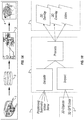
Fig. 1A diagrammatically depicts a system according to an embodiment of the invention. This system includes an ROV and its associatedinstrumentation 1, an operating system housed withincomputer hardware 3 and a user interface and its associateddevices 2. Theoperating system 3 mediates interaction between theROV 1 and theuser 4, such that the user may submit commands and inquiries for information to theROV 1, and obtain mechanical responses and data output from theROV 1. - As seen from
Fig. 1B , theoperating system 3 may receive live information obtained by the ROV's 1 multibeam 3D real-time sonar, telemetry data, positioning data and video as well as programmed 3D objects from adatabase 5, and process that data to provide live 3D models of the environment for both augmented reality and full 3D rendering displayed at theuser interface 2. Theuser interface 2 may also be used to display video obtained using the ROV's 1 digital instrumentation, including, for example, cameras and other sensors. TheROV 1 utilized in the system of the present invention is equipped with conventional instrumentation for telemetry and positioning, which are responsive to the commands mediated by theoperating system 3. - In one embodiment of the invention, the hardware for the
operating system 3 includes a high-end rack computer that can be easily integrated with any ROV control system. The several software modules that further define the operating system will be described in further detail infra. - With reference to
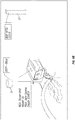
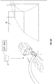
Figs. 2A and 2B , the human-machine interface includes at least onemonitor 7, and preferably threeinteractive monitors 7 for navigation. According to one embodiment shown inFig. 2A , thecenter monitor 7 provides a video feed and augmented reality (AR), while the side monitors provide an expansion of the field of view of operation. In another aspect, the side monitors may allow the user to have a panoramic view of the ROV environment using full 3D visualization from the point of view of the ROV. As seen inFig. 2B , the interaction between the user and the system may utilizejoysticks 8 or gamepads. In another embodiment, theuser interface 2 may employ touch or multi-touch screen technology, audio warnings and sounds, voice commands, a computer mouse, etc. - Rather than developing a
different operating system 3 for each brand and model ofROV 1, the present invention works by abstraction, such that the disclosedoperating system 3 and associated hardware work the same way with allROVs 1. For example, if one component delivers "$DBS,14.0,10.3" as a depth and heading coordinates, and another component delivers "$HD,15.3,16.4" as heading and depth coordinates, these data strings are parsed into their respective variables: Depth1=14.0, Depth2=16.4, Heading1=16.4, Heading2=15.3. This parsing allows both system to work the same way, regardless of the data format details. - By developing a layer of abstraction of drivers for communication between the
operating system 3 and the ROV hardware, theuser 4 is provided with seamless data communication, and is not restricted to using particular ROV models. This abstraction further allowsusers 4 andsystems 3 to communicate and network information between several systems, and share information among several undersea projects. The use of a single system also allows for cost reduction in training, maintenance and operation of this system. -
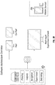
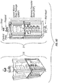
Fig. 3A depicts a software architecture overview illustrating the component parts of theROV 1,user interface 2 andoperating system 3. Software counterparts are provided for the ROV's telemetry, positioning, video and sonar instrumentation. In order to implement user functions including planning, logging, navigation, supervision and debriefing, theoperating system 3 provides a navigation engine, a visualization engine and a data engine. Theoperating system 3 is networked such that connected services and external command units can provide real-time data input. One of such external command units may be configured as a watchdog. The external watchdog system may perform periodic checks to determine whether the system is working properly, or is in a fail state. If the system is in a fail state, the watchdog may change the monitors' inputs, or bypass them, to a conventional live video feed until the system is operating correctly. -
Fig. 3B depicts a further software architecture overview illustrating that theoperating system 3, which mediates the aforementioned user functions, is networked to provide communication between a multi touch supervision console and a pilot or pilots.Fig. 3C illustrates yet another level of connectivity, wherein the navigation system of a first ROV may share all of its dynamic data with the navigation system of another ROV over a network. - As seen from
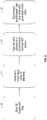
Figs. 1B and3A , the operating system's 3 visualization engine further includes modules for implementing 3D imagery, two-dimensional ("2D") imagery, and providing a real-time environment update. These modules are shown inFig. 4 , which illustrates in a stepwise fashion how the system operates to create superimposedhybrid 3D imagery. - A
3D database module 10 includes advanced 3D rendering technology to allow all the stages of ROV operation to be executed with reference to a visually re-created 3D deep-water environment. This environment is composed by the seabed bathymetry and modeled equipment, e.g., structures of ocean energy devices. - As discussed above, the main sources of image data are prerecorded 3D modeling of sonar data (i.e., computer-generated 3D video) and possibly other video data; live sonar data and video data obtained in real time; user-determined 3D elements; and textual or graphical communications intended to be displayed on the user interface screen. The geographical position and depth of any elements or regions included in the image data are known by GPS positioning, by use of acoustic and/or inertial positioning systems, and/or by reference to maps.
- In a preferred embodiment of the invention, a virtual
video generation module 11 is provided for using the aforementioned stored 3D elements or real-time detected 3D elements to create a virtual video of such 3D elements. The virtualvideo generation module 11 may work in concert with asynchronization module 12. - The
synchronization module 12 aligns the position of the virtual camera of the virtual video with the angle and position of a real camera on an ROV. The virtual camera defines a field of view for the virtual video, which extends between 45 and 144 degrees from a central point of view. As illustrated inFig. 5A , the alignment of virtual and real camera angles is accomplished by calculating the angle between the heading of the ROV and the direction of the camera field of view; calculating the angle between the vertical of the ROV and the direction of the camera field of view; and calculating the angle between the ROV and the geographic horizon. These calculated angles are then used to determine an equivalent object screen coordinate of the digital X-Y axis at determined time intervals or anytime a variable changes value. - A
superimposition module 13, whose function is additionally diagrammed inFig. 5B , is provided for superimposing the generatedvirtual video 20 and the synchronized, real-time video 21 acquired by the ROVs digital camera. The result is hybrid superimposed3D imagery 22, wherein the system effectively draws the generated 3D environment on top of the non-visible part of the video feed, thus greatly enhancing visibility for the ROV pilot. More specifically, the superimposition software divides the camera-feed video and the generated 3D video into several layers on the z-buffer of the 3D rendering system. This permits the flattening of the layers and their superimposition, which simulates spatial perception and facilitates navigation. - The
superimposition module 13 manipulates either one or both of the virtual 20 orreal videos 21, based upon a luminance threshold, to be more transparent in areas of lesser interest, thus allowing the corresponding area of the other video feed to show through. According to one embodiment of the invention, luminance in the Red-Green-Blue hexadecimal format may be between 0-0-0 and 255-255-255, and preferably between 0-0-0 and 40-40-40. Areas of lesser interest may be selected by a system default, or by the user. The color intensity of images in areas of lesser interest is set at the luminance threshold, and the corresponding region of the other video is set at normal luminance. For the example shown inFig. 5B , the background of thevirtual video 20 is kept relatively more transparent than the foreground. Thus, when thereal video 21 is superimposed on thevirtual 3D image 20, thereal video 21 is selectively augmented primarily with the virtual foreground, which contains a subsea structure of interest. - The on-screen, 2D Navigation Interface for the ROV pilot involves superimposing geopositioned data or technical information on a 2D rendering system. Geopositioning or geo-tagging of data and elements is executed by reference to maps or to global positioning satellites. The resulting Navigation Interface, as seen in
Figs. 6A-6D , is reminiscent of aviation-type heads up display consoles. In the case of subsea navigation, the display is configured to indicateROV 1 position based on known coordinates, and by using a sonar system that records 3D images from a ROV's position for later navigation. In this way, the present invention provides immersive visualization of ROV's operation. -
Fig. 6A illustrates the superposition of textual information andsymbols 30 onto the 2D video rendering of the ROV user interface.Fig. 6B illustrates the superposition of3D elements 31 onto the video rendering. The superposition of these data onto the video feed is useful, not only for navigating and controlling theROV 1, but also for executing the related planning and supervising functions of theoperating system 3. This superposition may be accomplished in a similar way to the superimposition of the video feeds, i.e., by obtaining screen coordinates of an object, and rendering text and numbers near those coordinates. - The planning module enables engineers and/or supervisors to plan one or several ROV missions. Referring again to
Fig. 6A , an important feature of the planning module is the input and presentation ofbathymetry information 32 through 3D visualization. As seen on the Navigation Interface,waypoints 33 andcheckpoints 34 are superimposed onto the video feed. These elements may be identified, for example, by number, and/or by distance from a reference point. In other words, in addition to superimposing the technical specifications andstatus information 30 for theROV 1 or other relevant structures, the Navigation Interface also provides GPS-determined positions for navigation and pilot information. -
Procedures 35, including timed procedures (fixed position observation tasks, for example), may be included on the Navigation Interface as text. Given this procedural information, a ROV pilot is enabled to anticipate and complete tasks more accurately. A user may also use the system to define actionable areas. Actionable areas are geopositioned areas in the undersea environment that trigger a system action when entering, leaving, or staying longer than a designated time. The triggered action could be an alarm, notification, procedure change, task change, etc. - Referring to
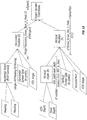
Fig. 6C , using a series of rules established in the planning module, or by manual input, the system may show more or less 2D geo-tagged information on the Navigation Interface. For example, as seen at 36, during a ROV operation when the pilot is at 100 meters from a geo-tagged object, the system may show only general information relating to the overall structure, or specific information needed for a specific current task in the nearby area. As the pilot approaches the geo-tagged structure, shown at 37, the system may incrementally show more information about components of that structure. This dynamic and manual level of detail control may apply to both textual andsymbolic information 30, as well as to the augmentation of3D elements 31. - With reference to
Fig. 6D , the planning module may also provide on-screen information relating toflight path 38. As seen inFig. 6E , another important feature of the invention is embodied by a minimap 39, i.e., a graphic superimposed on the video, which may include a variety of different representations, such as small icons representing target objects. The minimap 39 may show the cardinal points (North, South, East, West) in a 3D representation, optionally in addition to a representation of a relevant object in tridimensional space. The minimap 39 may be positioned in a corner, and may be moved, dismissed and recalled by the user. - The data engine, which mediates the data warehousing and data transfer functions of the invention, therefore incorporates the logging and supervising modules.
- The logging module logs or records all information made available by the operating system and saves such data in a central database for future access. The available information may include any or all telemetry, sonar data, 3D models, bathymetry, waypoints, checkpoints, alarms or malfunctions, procedures, operations, and navigation records such as flight path information, positioning and inertial data, etc.
- An essential part of any offshore operation providing critical data to the client after the operation is concluded. After the operation, during the debriefing and reporting stage, the debriefing and reporting module may provide a full 3D scenario or reproduction of the operation. The debriefing and reporting module may provide a report on the planned flight path versus the actual flight path, waypoints, checkpoints, several deviations on the plan, alarms given by the ROV, including details of alarm type, time and location, procedures, checkpoints, etc. ready to be delivered to the client. Accordingly, the operating system is configured to provide four-dimensional (three spatial dimensions plus time) interactive reports for every operation. This enables fast analysis and a comprehensive understanding of operations.
- Yet another software element that interacts with of the Navigation Interface is the supervisor module. Execution of the supervisor module enables one or more supervisors to view and/or utilize the Navigation Interface, and by extension, any
ROV 1 being controlled from the interface. These supervisors need not share the location of the ROV pilot or pilots, but rather may employ the connectivity elements depicted inFigs. 3B and3C . A plurality of multi touch supervision consoles may be used at different locations. For example, one could have nine monitors connected to three exemplary hardware structures, including anROV 1, where only oneoperating system 3 gathered the ROV data and shared information with the others. Alternatively, between one and 12 networked monitors may be used, and preferably between 3 and 9 may be used. Networking provided as shown inFigs. 3B and3C may reduce risks, such as human error, in multiple-ROV operations, even those coordinated from separate vessels. Networking through the supervisor module allows for the sharing of information between ROV systems, personnel and operations across the entire operation workflow. - Thus, there has been shown and described a system and method relating to navigation and control of ROVs. The method and system are not limited to any particular hardware or software configuration. The many variations, modifications and alternative applications of the invention that would be apparent to those skilled in the art, and that do not depart from the scope of the claims are deemed to be covered by the invention.
Claims (16)
- A system for exploration comprising:a remote operated vehicle (ROV) (1), wherein said ROV (1) comprises a video camera for acquiring a live video feed (21);a networked operating system (3) comprising a visualization engine, wherein said visualization engine further comprises:a database module (10) of 3D elements representing objects disposed in an operation environment of said remote operated vehicle (1);a virtual video generating module (11) for generating a virtual video feed (20) incorporating said 3D elements;a synchronizing module (12) for synchronizing an angle and position of a virtual camera with an angle and position of the video camera mounted to the vehicle, wherein the virtual camera defines a field of view for the virtual video feed (20), wherein the field of view is between about 45 and 144 degrees from a central point of view; anda superimposition module (13) for superimposing said virtual video feed (20) and said live video feed (21), wherein said superimposition module (13) is configured to modulate the transparency or opaqueness of a region of lesser interest in one of the virtual or live video feeds (20, 21) based on a luminance threshold, such that a corresponding region of the other video feed is more visible, said superimposed virtual and live video feeds (20, 21) comprising hybrid 3D imagery (22); anda navigation interface (2) configured to display said hybrid 3D imagery (22), said navigating interface (2) comprising at least one networked monitor (7),characterised in that, synchronizing the angle and position of the video camera comprises the steps of:calculating an angle between a heading of the vehicle (1) and a direction of a field of view of the video camera;calculating an angle between a vertical orientation of the vehicle (1) and the direction of the video camera field of view; andcalculating an angle between the vehicle (1) and a geographic horizon.
- The system according to claim 1, wherein the superimposition module (13) is configured to superimpose graphic information, textual information, or both, onto the hybrid 3D imagery (22).
- The system according to either claim 1 or 2, wherein the luminance threshold is in Red-Green-Blue hexadecimal format, and wherein luminance is set to values between 0-0-0 and 255-255-255.
- The system according to any one of claims 1 - 3, wherein the operating system is capable of sharing data with a plurality of remote monitors, said plurality comprising up to 12 remote monitors, and between 3 and 9 remote monitors.
- The system according to any one of claims 1 - 4, further comprising an external system configured to determine whether the system is working or is in a fail state.
- The system according to claim 5, wherein the external system is configured to switch the monitor input from hybrid 3D imagery (22) to said live video feed (21) if the system is in a fail state.
- The system according to any one of claims 1 - 6, wherein the navigation interface (2) comprises at least three networked monitors (7), wherein said monitors (7) are arranged adjacent to one another such that the middle monitor displays superimposed virtual and live video feeds (20, 21), while both side monitors display an expanded view of a field of operation.
- The system according to any of claims 1 - 7, wherein the 3D elements are obtained from any of pre-recorded sonar data, live sonar data, programmed 3D objects, user-determined inputs, and bathymetry.
- A method for exploration, comprising:storing 3D elements in a database module (10), said 3D elements representing objects disposed in a remotely operated vehicle's (1) operation environment;generating a virtual video feed (20) of said 3D elements;obtaining a live video feed (21) using a video camera;synchronizing an angle and position of a virtual camera with an angle and position of the video camera mounted to the remotely operated vehicle (1), wherein the virtual camera defines a field of view for the virtual video feed (20); andsuperimposing said virtual video feed (20) and said live video feed (21) on a video screen, wherein superimposing further comprises the step of modulating the transparency or opaqueness of a region of lesser interest in one of the virtual or live video feeds (20, 21) based on a luminance threshold, such that a corresponding region of the other video feed is more visible, said superimposed virtual and live video feeds (20, 21) comprising hybrid 3D imagery (22),characterised in that, synchronizing the angle and position of the video camera comprises the steps of:calculating an angle between a heading of the vehicle (1) and a direction of a field of view of the video camera;calculating an angle between a vertical orientation of the vehicle (1) and the direction of the video camera field of view; andcalculating an angle between the vehicle (1) and a geographic horizon.
- The method according to claim 9, further comprising superimposing graphic information, textual information, or both, onto the hybrid 3D imagery (22).
- The method according to claim 9, wherein the modulation based on the luminance threshold comprises maintaining a background of the virtual video feed (20) at a higher transparency than the background of the real video feed (21).
- The method according to one of claims 9 - 11, wherein the step of superimposing further comprises modulating the amount of 2D or 3D information superimposed onto the video screen based on the position of the ROV (1) relative to objects disposed in the remotely operated vehicle's (1) operation environment.
- The method according to one of claims 9 - 12, wherein the step of superimposing further comprises providing a minimap (39), said minimap (39) defining a computer-generated graphic showing either or both cardinal points or a position of an object in 3D.
- The method according to any of claims 9 - 13, comprising the step of configuring the operating system such that entering, leaving, or remaining longer than a designated time at a GPS-determined position triggers any one or combination of an alarm, notification, procedure change or task change.
- The method according to any of claims 9 - 14, wherein the 3D elements are obtained from any of pre-recorded sonar data, live sonar data, programmed 3D objects, user-determined inputs, and bathymetry.
- A computer program product, stored on a computer-readable medium, for implementing the method according to any one of claims 9 - 15.
Priority Applications (1)
| Application Number | Priority Date | Filing Date | Title |
|---|---|---|---|
| HRP20211664TT HRP20211664T1 (en) | 2011-11-09 | 2012-11-08 | System and method of operation for remotely operated vehicles with superimposed 3d imagery |
Applications Claiming Priority (3)
| Application Number | Priority Date | Filing Date | Title |
|---|---|---|---|
| PT10598911 | 2011-11-09 | ||
| US201261681411P | 2012-08-09 | 2012-08-09 | |
| PCT/IB2012/002281 WO2013068821A2 (en) | 2011-11-09 | 2012-11-08 | System and method of operation for remotely operated vehicles with superimposed 3d imagery |
Related Child Applications (1)
| Application Number | Title | Priority Date | Filing Date |
|---|---|---|---|
| EP21183096.3 Division-Into | 2021-07-01 |
Publications (2)
| Publication Number | Publication Date |
|---|---|
| EP2777024A2 EP2777024A2 (en) | 2014-09-17 |
| EP2777024B1 true EP2777024B1 (en) | 2021-08-04 |
Family
ID=48290705
Family Applications (1)
| Application Number | Title | Priority Date | Filing Date |
|---|---|---|---|
| EP12791544.5A Active EP2777024B1 (en) | 2011-11-09 | 2012-11-08 | System and method of operation for remotely operated vehicles with superimposed 3d imagery |
Country Status (10)
| Country | Link |
|---|---|
| US (3) | US9195231B2 (en) |
| EP (1) | EP2777024B1 (en) |
| AU (3) | AU2012335330B2 (en) |
| BR (1) | BR112014011172B1 (en) |
| CA (1) | CA2854595C (en) |
| ES (1) | ES2895454T3 (en) |
| HR (1) | HRP20211664T1 (en) |
| PT (1) | PT2777024T (en) |
| SG (1) | SG11201402114PA (en) |
| WO (1) | WO2013068821A2 (en) |
Families Citing this family (38)
| Publication number | Priority date | Publication date | Assignee | Title |
|---|---|---|---|---|
| US9043483B2 (en) | 2008-03-17 | 2015-05-26 | International Business Machines Corporation | View selection in a vehicle-to-vehicle network |
| US9123241B2 (en) | 2008-03-17 | 2015-09-01 | International Business Machines Corporation | Guided video feed selection in a vehicle-to-vehicle network |
| AU2012335330B2 (en) * | 2011-11-09 | 2017-07-20 | Ocean Infinity (Portugal), S.A. | System and method of operation for remotely operated vehicles with superimposed 3D imagery |
| US9754507B1 (en) * | 2013-07-02 | 2017-09-05 | Rockwell Collins, Inc. | Virtual/live hybrid behavior to mitigate range and behavior constraints |
| WO2016073060A2 (en) * | 2014-09-02 | 2016-05-12 | Flir Systems, Inc. | Augmented reality sonar imagery systems and methods |
| GB201405527D0 (en) * | 2014-03-27 | 2014-05-14 | Mill Facility The Ltd | A driveable vehicle unit |
| DE102014107211A1 (en) * | 2014-05-22 | 2015-11-26 | Atlas Elektronik Gmbh | Device for displaying a virtual reality as well as measuring device |
| US10802141B2 (en) | 2014-05-30 | 2020-10-13 | FLIR Belgium BVBA | Water temperature overlay systems and methods |
| US11181637B2 (en) | 2014-09-02 | 2021-11-23 | FLIR Belgium BVBA | Three dimensional target selection systems and methods |
| US10444349B2 (en) | 2014-09-02 | 2019-10-15 | FLIR Belgium BVBA | Waypoint sharing systems and methods |
| NL2013804B1 (en) * | 2014-11-14 | 2016-10-07 | Fugro Subsea Services Ltd | A method of controlling a subsea platform, a system and a computer program product. |
| US20160259051A1 (en) | 2015-03-05 | 2016-09-08 | Navico Holding As | Systems and associated methods for producing a 3d sonar image |
| US10176643B2 (en) * | 2015-03-30 | 2019-01-08 | Capcom Co., Ltd. | Method of generating virtual three-dimensional space, video system, method of controlling video system, and non-transitory computer readable storage medium |
| FR3037429B1 (en) * | 2015-06-15 | 2018-09-07 | Donecle | SYSTEM AND METHOD FOR AUTOMATIC SURFACE INSPECTION |
| US20170094227A1 (en) * | 2015-09-25 | 2017-03-30 | Northrop Grumman Systems Corporation | Three-dimensional spatial-awareness vision system |
| CA2948761A1 (en) * | 2015-11-23 | 2017-05-23 | Wal-Mart Stores, Inc. | Virtual training system |
| CN105679169A (en) * | 2015-12-31 | 2016-06-15 | 中国神华能源股份有限公司 | Railway electronic sand table system |
| CN115686005A (en) | 2016-06-28 | 2023-02-03 | 柯尼亚塔有限公司 | System and computer-implemented method for training a virtual model of an automated driving system |
| GB2557572B (en) * | 2016-09-20 | 2020-02-12 | Subsea 7 Ltd | Performing remote inspection at subsea locations |
| IL251189A0 (en) | 2017-03-15 | 2017-06-29 | Ophir Yoav | Gradual transitioning between two-dimensional and theree-dimensional augmented reality images |
| US20200386552A1 (en) * | 2017-07-18 | 2020-12-10 | Bechtel Oil, Gas & Chemicals, Inc. | Primary navigation system for tugboats with an obstructed pilot view |
| GB2565101A (en) * | 2017-08-01 | 2019-02-06 | Lobster Pictures Ltd | Method for integrating photographic images and BIM data |
| WO2019109083A1 (en) * | 2017-12-01 | 2019-06-06 | Onesubsea Ip Uk Limited | Systems and methods of pilot assist for subsea vehicles |
| US11010975B1 (en) | 2018-03-06 | 2021-05-18 | Velan Studios, Inc. | Remote camera augmented reality system |
| WO2020030950A1 (en) * | 2018-08-08 | 2020-02-13 | Abyssal S.A. | System and method of operation for remotely operated vehicles leveraging synthetic data to train machine learning models |
| WO2020030948A1 (en) | 2018-08-08 | 2020-02-13 | Abyssal S.A. | System and method of operation for remotely operated vehicles with improved position estimation |
| AU2018436495B2 (en) * | 2018-08-08 | 2023-08-10 | Ocean Infinity (Portugal), S.A. | System and method of operation for remotely operated vehicles for automatic detection of structure integrity threats |
| WO2020030951A1 (en) | 2018-08-08 | 2020-02-13 | Abyssal S.A. | System and method of operation for remotely operated vehicles for simultaneous localization and mapping |
| GB2578592B (en) * | 2018-10-31 | 2023-07-05 | Sony Interactive Entertainment Inc | Apparatus and method of video playback |
| EP3712558A1 (en) | 2019-03-21 | 2020-09-23 | Rovco Limited | Surveying system for surveying in harsh environments |
| US11048760B1 (en) * | 2019-07-31 | 2021-06-29 | Splunk Inc. | Techniques for placing content in and applying layers in an extended reality environment |
| US11228737B2 (en) * | 2019-07-31 | 2022-01-18 | Ricoh Company, Ltd. | Output control apparatus, display terminal, remote control system, control method, and non-transitory computer-readable medium |
| US12365431B2 (en) | 2019-10-07 | 2025-07-22 | Onesubsea Ip Uk Limited | Underwater vehicle control system |
| GB2598345B (en) | 2020-08-27 | 2023-04-19 | Extend Robotics Ltd | Remote operation of robotic systems |
| US20230260240A1 (en) * | 2021-03-11 | 2023-08-17 | Quintar, Inc. | Alignment of 3d graphics extending beyond frame in augmented reality system with remote presentation |
| CN113500601B (en) * | 2021-07-21 | 2022-11-22 | 上海原圈网络科技有限公司 | Robot motion control method and system |
| US11948257B2 (en) | 2022-05-09 | 2024-04-02 | Rovi Guides, Inc. | Systems and methods for augmented reality video generation |
| US20250033749A1 (en) * | 2023-03-09 | 2025-01-30 | Cardinal Point Captains, Inc. | Systems and methods for creating a mission file for an underwater handheld computer |
Family Cites Families (21)
| Publication number | Priority date | Publication date | Assignee | Title |
|---|---|---|---|---|
| US5412569A (en) | 1994-03-29 | 1995-05-02 | General Electric Company | Augmented reality maintenance system with archive and comparison device |
| US5706195A (en) * | 1995-09-05 | 1998-01-06 | General Electric Company | Augmented reality maintenance system for multiple rovs |
| WO1998057222A1 (en) * | 1997-06-10 | 1998-12-17 | Lg. Philips Lcd Co., Ltd. | Liquid crystal display with wide viewing angle and method for making it |
| JPH11139390A (en) | 1997-11-10 | 1999-05-25 | Ishikawajima Harima Heavy Ind Co Ltd | Underwater object search device |
| US6330356B1 (en) | 1999-09-29 | 2001-12-11 | Rockwell Science Center Llc | Dynamic visual registration of a 3-D object with a graphical model |
| JP5306566B2 (en) | 2000-05-01 | 2013-10-02 | アイロボット コーポレーション | Method and system for remotely controlling a mobile robot |
| US8015507B2 (en) | 2001-11-05 | 2011-09-06 | H2Eye (International) Limited | Graphical user interface for a remote operated vehicle |
| US7071970B2 (en) * | 2003-03-10 | 2006-07-04 | Charles Benton | Video augmented orientation sensor |
| US7292257B2 (en) * | 2004-06-28 | 2007-11-06 | Microsoft Corporation | Interactive viewpoint video system and process |
| KR101238608B1 (en) | 2004-07-30 | 2013-02-28 | 익스트림 리얼리티 엘티디. | A system and method for 3D space-dimension based image processing |
| US8423292B2 (en) * | 2008-08-19 | 2013-04-16 | Tomtom International B.V. | Navigation device with camera-info |
| US8577538B2 (en) * | 2006-07-14 | 2013-11-05 | Irobot Corporation | Method and system for controlling a remote vehicle |
| US7352292B2 (en) | 2006-01-20 | 2008-04-01 | Keith Alter | Real-time, three-dimensional synthetic vision display of sensor-validated terrain data |
| US7693617B2 (en) * | 2006-09-19 | 2010-04-06 | The Boeing Company | Aircraft precision approach control |
| US8301318B2 (en) * | 2008-03-05 | 2012-10-30 | Robotic Research Llc | Robotic vehicle remote control system having a virtual operator environment |
| US20100091036A1 (en) * | 2008-10-10 | 2010-04-15 | Honeywell International Inc. | Method and System for Integrating Virtual Entities Within Live Video |
| GB2464985A (en) | 2008-11-03 | 2010-05-05 | Wireless Fibre Systems Ltd | Underwater Vehicle Guidance |
| FR2949167B1 (en) | 2009-08-11 | 2016-07-01 | Alain Dinis | SYSTEM AND METHOD FOR REAL-TIME VIRTUAL DIVING |
| US20110153189A1 (en) | 2009-12-17 | 2011-06-23 | Garmin Ltd. | Historical traffic data compression |
| US8725273B2 (en) | 2010-02-17 | 2014-05-13 | Irobot Corporation | Situational awareness for teleoperation of a remote vehicle |
| AU2012335330B2 (en) * | 2011-11-09 | 2017-07-20 | Ocean Infinity (Portugal), S.A. | System and method of operation for remotely operated vehicles with superimposed 3D imagery |
-
2012
- 2012-11-08 AU AU2012335330A patent/AU2012335330B2/en active Active
- 2012-11-08 WO PCT/IB2012/002281 patent/WO2013068821A2/en not_active Ceased
- 2012-11-08 HR HRP20211664TT patent/HRP20211664T1/en unknown
- 2012-11-08 SG SG11201402114PA patent/SG11201402114PA/en unknown
- 2012-11-08 ES ES12791544T patent/ES2895454T3/en active Active
- 2012-11-08 US US14/357,100 patent/US9195231B2/en active Active
- 2012-11-08 EP EP12791544.5A patent/EP2777024B1/en active Active
- 2012-11-08 CA CA2854595A patent/CA2854595C/en active Active
- 2012-11-08 PT PT127915445T patent/PT2777024T/en unknown
- 2012-11-08 BR BR112014011172-3A patent/BR112014011172B1/en active IP Right Grant
-
2015
- 2015-11-09 US US14/935,979 patent/US9741173B2/en active Active
-
2017
- 2017-07-20 US US15/654,974 patent/US10424119B2/en active Active
- 2017-09-29 AU AU2017236009A patent/AU2017236009B2/en active Active
-
2019
- 2019-11-14 AU AU2019264604A patent/AU2019264604B2/en active Active
Non-Patent Citations (2)
| Title |
|---|
| MARK BILLINGHURST ET AL: "A Survey of Augmented Reality", FOUNDATIONS AND TRENDS? IN HUMAN-COMPUTER INTERACTION, vol. 8, no. 2-3, 1 January 2015 (2015-01-01), pages 73 - 272, XP055421092, ISSN: 1551-3955, DOI: 10.1561/1100000049 * |
| RONALD T AZUMA: "A Survey of Augmented Reality", PRESENCE: TELEOPERATORS AND VIRTUAL ENVIRONMENTS,, vol. 6, no. 4, 1 August 1997 (1997-08-01), pages 355 - 385, XP055178317, DOI: 10.1162/pres.1997.6.4.355 * |
Also Published As
| Publication number | Publication date |
|---|---|
| AU2012335330B2 (en) | 2017-07-20 |
| AU2019264604A1 (en) | 2019-12-05 |
| WO2013068821A3 (en) | 2014-04-24 |
| US10424119B2 (en) | 2019-09-24 |
| AU2019264604B2 (en) | 2020-05-21 |
| CA2854595C (en) | 2022-04-26 |
| EP2777024A2 (en) | 2014-09-17 |
| PT2777024T (en) | 2021-11-08 |
| BR112014011172B1 (en) | 2021-07-27 |
| HRP20211664T1 (en) | 2022-02-18 |
| US9741173B2 (en) | 2017-08-22 |
| US20160063768A1 (en) | 2016-03-03 |
| AU2017236009B2 (en) | 2019-08-22 |
| WO2013068821A2 (en) | 2013-05-16 |
| AU2017236009A1 (en) | 2017-10-26 |
| CA2854595A1 (en) | 2013-05-16 |
| US20140316611A1 (en) | 2014-10-23 |
| SG11201402114PA (en) | 2014-06-27 |
| BR112014011172A2 (en) | 2017-05-09 |
| ES2895454T3 (en) | 2022-02-21 |
| AU2012335330A1 (en) | 2014-06-05 |
| US9195231B2 (en) | 2015-11-24 |
| US20170323487A1 (en) | 2017-11-09 |
Similar Documents
| Publication | Publication Date | Title |
|---|---|---|
| AU2019264604B2 (en) | System and method of operation for remotely operated vehicles with superimposed 3d imagery | |
| AU2018436279B2 (en) | System and method of operation for remotely operated vehicles for simultaneous localization and mapping | |
| AU2018435825B2 (en) | System and method of operation for remotely operated vehicles leveraging synthetic data to train machine learning models | |
| AU2018436495B2 (en) | System and method of operation for remotely operated vehicles for automatic detection of structure integrity threats | |
| US11436807B2 (en) | System and method of operation for remotely operated vehicles with improved position estimation |
Legal Events
| Date | Code | Title | Description |
|---|---|---|---|
| REG | Reference to a national code |
Ref country code: HR Ref legal event code: TUEP Ref document number: P20211664 Country of ref document: HR |
|
| PUAI | Public reference made under article 153(3) epc to a published international application that has entered the european phase |
Free format text: ORIGINAL CODE: 0009012 |
|
| 17P | Request for examination filed |
Effective date: 20140512 |
|
| AK | Designated contracting states |
Kind code of ref document: A2 Designated state(s): AL AT BE BG CH CY CZ DE DK EE ES FI FR GB GR HR HU IE IS IT LI LT LU LV MC MK MT NL NO PL PT RO RS SE SI SK SM TR |
|
| DAX | Request for extension of the european patent (deleted) | ||
| STAA | Information on the status of an ep patent application or granted ep patent |
Free format text: STATUS: EXAMINATION IS IN PROGRESS |
|
| 17Q | First examination report despatched |
Effective date: 20181129 |
|
| GRAP | Despatch of communication of intention to grant a patent |
Free format text: ORIGINAL CODE: EPIDOSNIGR1 |
|
| STAA | Information on the status of an ep patent application or granted ep patent |
Free format text: STATUS: GRANT OF PATENT IS INTENDED |
|
| INTG | Intention to grant announced |
Effective date: 20210311 |
|
| GRAS | Grant fee paid |
Free format text: ORIGINAL CODE: EPIDOSNIGR3 |
|
| GRAA | (expected) grant |
Free format text: ORIGINAL CODE: 0009210 |
|
| STAA | Information on the status of an ep patent application or granted ep patent |
Free format text: STATUS: THE PATENT HAS BEEN GRANTED |
|
| AK | Designated contracting states |
Kind code of ref document: B1 Designated state(s): AL AT BE BG CH CY CZ DE DK EE ES FI FR GB GR HR HU IE IS IT LI LT LU LV MC MK MT NL NO PL PT RO RS SE SI SK SM TR |
|
| REG | Reference to a national code |
Ref country code: GB Ref legal event code: FG4D |
|
| REG | Reference to a national code |
Ref country code: AT Ref legal event code: REF Ref document number: 1417782 Country of ref document: AT Kind code of ref document: T Effective date: 20210815 |
|
| REG | Reference to a national code |
Ref country code: CH Ref legal event code: EP |
|
| REG | Reference to a national code |
Ref country code: DE Ref legal event code: R096 Ref document number: 602012076304 Country of ref document: DE |
|
| REG | Reference to a national code |
Ref country code: IE Ref legal event code: FG4D |
|
| REG | Reference to a national code |
Ref country code: DK Ref legal event code: T3 Effective date: 20211019 |
|
| REG | Reference to a national code |
Ref country code: FI Ref legal event code: FGE |
|
| REG | Reference to a national code |
Ref country code: PT Ref legal event code: SC4A Ref document number: 2777024 Country of ref document: PT Date of ref document: 20211108 Kind code of ref document: T Free format text: AVAILABILITY OF NATIONAL TRANSLATION Effective date: 20211029 |
|
| REG | Reference to a national code |
Ref country code: NL Ref legal event code: FP |
|
| REG | Reference to a national code |
Ref country code: SE Ref legal event code: TRGR |
|
| REG | Reference to a national code |
Ref country code: LT Ref legal event code: MG9D |
|
| REG | Reference to a national code |
Ref country code: GR Ref legal event code: EP Ref document number: 20210402896 Country of ref document: GR Effective date: 20211209 |
|
| REG | Reference to a national code |
Ref country code: AT Ref legal event code: MK05 Ref document number: 1417782 Country of ref document: AT Kind code of ref document: T Effective date: 20210804 |
|
| REG | Reference to a national code |
Ref country code: NO Ref legal event code: T2 Effective date: 20210804 |
|
| PG25 | Lapsed in a contracting state [announced via postgrant information from national office to epo] |
Ref country code: RS Free format text: LAPSE BECAUSE OF FAILURE TO SUBMIT A TRANSLATION OF THE DESCRIPTION OR TO PAY THE FEE WITHIN THE PRESCRIBED TIME-LIMIT Effective date: 20210804 Ref country code: AT Free format text: LAPSE BECAUSE OF FAILURE TO SUBMIT A TRANSLATION OF THE DESCRIPTION OR TO PAY THE FEE WITHIN THE PRESCRIBED TIME-LIMIT Effective date: 20210804 Ref country code: BG Free format text: LAPSE BECAUSE OF FAILURE TO SUBMIT A TRANSLATION OF THE DESCRIPTION OR TO PAY THE FEE WITHIN THE PRESCRIBED TIME-LIMIT Effective date: 20211104 Ref country code: LT Free format text: LAPSE BECAUSE OF FAILURE TO SUBMIT A TRANSLATION OF THE DESCRIPTION OR TO PAY THE FEE WITHIN THE PRESCRIBED TIME-LIMIT Effective date: 20210804 |
|
| REG | Reference to a national code |
Ref country code: HR Ref legal event code: T1PR Ref document number: P20211664 Country of ref document: HR |
|
| REG | Reference to a national code |
Ref country code: ES Ref legal event code: FG2A Ref document number: 2895454 Country of ref document: ES Kind code of ref document: T3 Effective date: 20220221 |
|
| PG25 | Lapsed in a contracting state [announced via postgrant information from national office to epo] |
Ref country code: PL Free format text: LAPSE BECAUSE OF FAILURE TO SUBMIT A TRANSLATION OF THE DESCRIPTION OR TO PAY THE FEE WITHIN THE PRESCRIBED TIME-LIMIT Effective date: 20210804 Ref country code: LV Free format text: LAPSE BECAUSE OF FAILURE TO SUBMIT A TRANSLATION OF THE DESCRIPTION OR TO PAY THE FEE WITHIN THE PRESCRIBED TIME-LIMIT Effective date: 20210804 |
|
| REG | Reference to a national code |
Ref country code: HR Ref legal event code: ODRP Ref document number: P20211664 Country of ref document: HR Payment date: 20220211 Year of fee payment: 10 |
|
| REG | Reference to a national code |
Ref country code: DE Ref legal event code: R097 Ref document number: 602012076304 Country of ref document: DE |
|
| PG25 | Lapsed in a contracting state [announced via postgrant information from national office to epo] |
Ref country code: SM Free format text: LAPSE BECAUSE OF FAILURE TO SUBMIT A TRANSLATION OF THE DESCRIPTION OR TO PAY THE FEE WITHIN THE PRESCRIBED TIME-LIMIT Effective date: 20210804 Ref country code: SK Free format text: LAPSE BECAUSE OF FAILURE TO SUBMIT A TRANSLATION OF THE DESCRIPTION OR TO PAY THE FEE WITHIN THE PRESCRIBED TIME-LIMIT Effective date: 20210804 Ref country code: RO Free format text: LAPSE BECAUSE OF FAILURE TO SUBMIT A TRANSLATION OF THE DESCRIPTION OR TO PAY THE FEE WITHIN THE PRESCRIBED TIME-LIMIT Effective date: 20210804 Ref country code: EE Free format text: LAPSE BECAUSE OF FAILURE TO SUBMIT A TRANSLATION OF THE DESCRIPTION OR TO PAY THE FEE WITHIN THE PRESCRIBED TIME-LIMIT Effective date: 20210804 Ref country code: CZ Free format text: LAPSE BECAUSE OF FAILURE TO SUBMIT A TRANSLATION OF THE DESCRIPTION OR TO PAY THE FEE WITHIN THE PRESCRIBED TIME-LIMIT Effective date: 20210804 Ref country code: AL Free format text: LAPSE BECAUSE OF FAILURE TO SUBMIT A TRANSLATION OF THE DESCRIPTION OR TO PAY THE FEE WITHIN THE PRESCRIBED TIME-LIMIT Effective date: 20210804 |
|
| PLBE | No opposition filed within time limit |
Free format text: ORIGINAL CODE: 0009261 |
|
| STAA | Information on the status of an ep patent application or granted ep patent |
Free format text: STATUS: NO OPPOSITION FILED WITHIN TIME LIMIT |
|
| PG25 | Lapsed in a contracting state [announced via postgrant information from national office to epo] |
Ref country code: MC Free format text: LAPSE BECAUSE OF FAILURE TO SUBMIT A TRANSLATION OF THE DESCRIPTION OR TO PAY THE FEE WITHIN THE PRESCRIBED TIME-LIMIT Effective date: 20210804 |
|
| REG | Reference to a national code |
Ref country code: CH Ref legal event code: PL |
|
| 26N | No opposition filed |
Effective date: 20220506 |
|
| PG25 | Lapsed in a contracting state [announced via postgrant information from national office to epo] |
Ref country code: LU Free format text: LAPSE BECAUSE OF NON-PAYMENT OF DUE FEES Effective date: 20211108 |
|
| PG25 | Lapsed in a contracting state [announced via postgrant information from national office to epo] |
Ref country code: SI Free format text: LAPSE BECAUSE OF FAILURE TO SUBMIT A TRANSLATION OF THE DESCRIPTION OR TO PAY THE FEE WITHIN THE PRESCRIBED TIME-LIMIT Effective date: 20210804 Ref country code: LI Free format text: LAPSE BECAUSE OF NON-PAYMENT OF DUE FEES Effective date: 20211130 Ref country code: CH Free format text: LAPSE BECAUSE OF NON-PAYMENT OF DUE FEES Effective date: 20211130 |
|
| REG | Reference to a national code |
Ref country code: HR Ref legal event code: ODRP Ref document number: P20211664 Country of ref document: HR Payment date: 20221103 Year of fee payment: 11 |
|
| PG25 | Lapsed in a contracting state [announced via postgrant information from national office to epo] |
Ref country code: HU Free format text: LAPSE BECAUSE OF FAILURE TO SUBMIT A TRANSLATION OF THE DESCRIPTION OR TO PAY THE FEE WITHIN THE PRESCRIBED TIME-LIMIT; INVALID AB INITIO Effective date: 20121108 Ref country code: CY Free format text: LAPSE BECAUSE OF FAILURE TO SUBMIT A TRANSLATION OF THE DESCRIPTION OR TO PAY THE FEE WITHIN THE PRESCRIBED TIME-LIMIT Effective date: 20210804 |
|
| P01 | Opt-out of the competence of the unified patent court (upc) registered |
Effective date: 20230530 |
|
| REG | Reference to a national code |
Ref country code: HR Ref legal event code: ODRP Ref document number: P20211664 Country of ref document: HR Payment date: 20231011 Year of fee payment: 12 |
|
| PG25 | Lapsed in a contracting state [announced via postgrant information from national office to epo] |
Ref country code: MK Free format text: LAPSE BECAUSE OF FAILURE TO SUBMIT A TRANSLATION OF THE DESCRIPTION OR TO PAY THE FEE WITHIN THE PRESCRIBED TIME-LIMIT Effective date: 20210804 |
|
| PG25 | Lapsed in a contracting state [announced via postgrant information from national office to epo] |
Ref country code: TR Free format text: LAPSE BECAUSE OF FAILURE TO SUBMIT A TRANSLATION OF THE DESCRIPTION OR TO PAY THE FEE WITHIN THE PRESCRIBED TIME-LIMIT Effective date: 20210804 |
|
| PG25 | Lapsed in a contracting state [announced via postgrant information from national office to epo] |
Ref country code: MT Free format text: LAPSE BECAUSE OF FAILURE TO SUBMIT A TRANSLATION OF THE DESCRIPTION OR TO PAY THE FEE WITHIN THE PRESCRIBED TIME-LIMIT Effective date: 20210804 |
|
| REG | Reference to a national code |
Ref country code: HR Ref legal event code: ODRP Ref document number: P20211664 Country of ref document: HR Payment date: 20241015 Year of fee payment: 13 |
|
| PGFP | Annual fee paid to national office [announced via postgrant information from national office to epo] |
Ref country code: FR Payment date: 20250930 Year of fee payment: 14 |
|
| PGFP | Annual fee paid to national office [announced via postgrant information from national office to epo] |
Ref country code: NL Payment date: 20251003 Year of fee payment: 14 |
|
| REG | Reference to a national code |
Ref country code: HR Ref legal event code: ODRP Ref document number: P20211664 Country of ref document: HR Payment date: 20251016 Year of fee payment: 14 |
|
| PGFP | Annual fee paid to national office [announced via postgrant information from national office to epo] |
Ref country code: PT Payment date: 20251107 Year of fee payment: 14 |
|
| PGFP | Annual fee paid to national office [announced via postgrant information from national office to epo] |
Ref country code: IS Payment date: 20251107 Year of fee payment: 14 Ref country code: DE Payment date: 20250930 Year of fee payment: 14 |
|
| PGFP | Annual fee paid to national office [announced via postgrant information from national office to epo] |
Ref country code: GB Payment date: 20251001 Year of fee payment: 14 |
|
| PGFP | Annual fee paid to national office [announced via postgrant information from national office to epo] |
Ref country code: NO Payment date: 20251113 Year of fee payment: 14 |
|
| PGFP | Annual fee paid to national office [announced via postgrant information from national office to epo] |
Ref country code: FI Payment date: 20251113 Year of fee payment: 14 Ref country code: DK Payment date: 20251112 Year of fee payment: 14 Ref country code: IT Payment date: 20251022 Year of fee payment: 14 |
|
| PGFP | Annual fee paid to national office [announced via postgrant information from national office to epo] |
Ref country code: HR Payment date: 20251016 Year of fee payment: 14 |
|
| PGFP | Annual fee paid to national office [announced via postgrant information from national office to epo] |
Ref country code: BE Payment date: 20251003 Year of fee payment: 14 Ref country code: GR Payment date: 20251014 Year of fee payment: 14 |
|
| PGFP | Annual fee paid to national office [announced via postgrant information from national office to epo] |
Ref country code: SE Payment date: 20251001 Year of fee payment: 14 |
|
| PGFP | Annual fee paid to national office [announced via postgrant information from national office to epo] |
Ref country code: IE Payment date: 20251001 Year of fee payment: 14 |
|
| PGFP | Annual fee paid to national office [announced via postgrant information from national office to epo] |
Ref country code: ES Payment date: 20251210 Year of fee payment: 14 |