EP2776876B1 - Routeur de longueurs d'onde destiné à un réseau optique passif - Google Patents
Routeur de longueurs d'onde destiné à un réseau optique passif Download PDFInfo
- Publication number
- EP2776876B1 EP2776876B1 EP12788395.7A EP12788395A EP2776876B1 EP 2776876 B1 EP2776876 B1 EP 2776876B1 EP 12788395 A EP12788395 A EP 12788395A EP 2776876 B1 EP2776876 B1 EP 2776876B1
- Authority
- EP
- European Patent Office
- Prior art keywords
- optical
- lateral array
- waveguide
- coupled
- router
- Prior art date
- Legal status (The legal status is an assumption and is not a legal conclusion. Google has not performed a legal analysis and makes no representation as to the accuracy of the status listed.)
- Active
Links
- 230000003287 optical effect Effects 0.000 title claims description 160
- 230000003595 spectral effect Effects 0.000 claims description 6
- 239000000758 substrate Substances 0.000 claims description 3
- 230000005540 biological transmission Effects 0.000 description 12
- 238000013461 design Methods 0.000 description 9
- 239000000835 fiber Substances 0.000 description 6
- 239000000463 material Substances 0.000 description 6
- 238000000034 method Methods 0.000 description 6
- 125000004122 cyclic group Chemical group 0.000 description 5
- 230000008878 coupling Effects 0.000 description 4
- 238000010168 coupling process Methods 0.000 description 4
- 238000005859 coupling reaction Methods 0.000 description 4
- 238000010586 diagram Methods 0.000 description 4
- 230000009467 reduction Effects 0.000 description 4
- 238000000926 separation method Methods 0.000 description 4
- VYPSYNLAJGMNEJ-UHFFFAOYSA-N Silicium dioxide Chemical compound O=[Si]=O VYPSYNLAJGMNEJ-UHFFFAOYSA-N 0.000 description 3
- 230000008901 benefit Effects 0.000 description 3
- 239000011162 core material Substances 0.000 description 3
- 230000009977 dual effect Effects 0.000 description 3
- 238000003780 insertion Methods 0.000 description 3
- 230000037431 insertion Effects 0.000 description 3
- 230000002093 peripheral effect Effects 0.000 description 3
- 230000004044 response Effects 0.000 description 3
- UIAFKZKHHVMJGS-UHFFFAOYSA-N 2,4-dihydroxybenzoic acid Chemical compound OC(=O)C1=CC=C(O)C=C1O UIAFKZKHHVMJGS-UHFFFAOYSA-N 0.000 description 2
- 230000009286 beneficial effect Effects 0.000 description 2
- 230000001419 dependent effect Effects 0.000 description 2
- 239000006185 dispersion Substances 0.000 description 2
- 238000007689 inspection Methods 0.000 description 2
- 238000012986 modification Methods 0.000 description 2
- 230000004048 modification Effects 0.000 description 2
- 239000013307 optical fiber Substances 0.000 description 2
- RYGMFSIKBFXOCR-UHFFFAOYSA-N Copper Chemical compound [Cu] RYGMFSIKBFXOCR-UHFFFAOYSA-N 0.000 description 1
- 230000008859 change Effects 0.000 description 1
- 238000006243 chemical reaction Methods 0.000 description 1
- 238000005253 cladding Methods 0.000 description 1
- 238000004891 communication Methods 0.000 description 1
- 230000000295 complement effect Effects 0.000 description 1
- 239000000470 constituent Substances 0.000 description 1
- 229910052802 copper Inorganic materials 0.000 description 1
- 239000010949 copper Substances 0.000 description 1
- 230000003247 decreasing effect Effects 0.000 description 1
- 230000002939 deleterious effect Effects 0.000 description 1
- 238000011982 device technology Methods 0.000 description 1
- 238000010348 incorporation Methods 0.000 description 1
- 238000002372 labelling Methods 0.000 description 1
- 230000000737 periodic effect Effects 0.000 description 1
- 239000002861 polymer material Substances 0.000 description 1
- 239000004065 semiconductor Substances 0.000 description 1
- 229910052710 silicon Inorganic materials 0.000 description 1
- 239000010703 silicon Substances 0.000 description 1
- 239000000377 silicon dioxide Substances 0.000 description 1
- 229910052814 silicon oxide Inorganic materials 0.000 description 1
- 230000002195 synergetic effect Effects 0.000 description 1
- 238000011144 upstream manufacturing Methods 0.000 description 1
Images


Classifications
-
- H—ELECTRICITY
- H04—ELECTRIC COMMUNICATION TECHNIQUE
- H04J—MULTIPLEX COMMUNICATION
- H04J14/00—Optical multiplex systems
- H04J14/02—Wavelength-division multiplex systems
- H04J14/0201—Add-and-drop multiplexing
- H04J14/0202—Arrangements therefor
- H04J14/0204—Broadcast and select arrangements, e.g. with an optical splitter at the input before adding or dropping
Definitions
- the present invention relates to optical communication equipment and, more specifically but not exclusively, to passive wavelength routers.
- An access network also known as a "first-mile network” connects a service provider's central office to businesses and residential subscribers. Access networks are also sometimes referred to in the literature as subscriber access networks or local loops.
- the bandwidth demand in access networks has been increasing rapidly, for example, because residential subscribers expect first-mile access solutions to provide high bandwidth and offer media-rich services.
- corporate users demand broadband infrastructure through which they can reliably connect their local-area networks to the Internet backbone.
- a passive optical network is an optical fiber-based access network that can typically provide much higher bandwidth than, e.g., traditional copper-based access networks.
- WDM wavelength-division multiplexing
- WDM-PONs have not been widely commercialized yet, partly due to their relatively high cost compared to conventional systems and partly due to immature device technologies and insufficiently developed network protocols and software to support various commercially viable WDM-PON architectures.
- US Patent Application US 2004/264857 A1 discloses an arrayed waveguide grating (AWG).
- the AWG includes an input PxM star coupler, an output MxQ star coupler, and M waveguides of unequal length connecting the input and output star couplers.
- US Patent Application US 2004/218259 A1 discloses an AWG with three separate Brillouin zones with an angular separation of outputs equivalent to the separation of the corresponding Brillouin zones.
- European Patent Application EP 1 150 143 A2 discloses a NxN waveguide grating router wherein a technique for maximizing N in a NxN WGR device for channels equally spaced either in frequency or in wavelength is suggested.
- European Patent Application EP 0 613 263 A1 discloses an optical network comprising a compact wavelength-dividing component.
- a passive arrayed-waveguide-grating (AWG) router that can be used to implement the dual functionality of a wavelength router and a 3-dB optical power splitter for one of its wavelength channels while functioning as a conventional wavelength router for the other wavelength channels.
- the passive AWG router can advantageously be used, e.g., in a WDM-PON system to reduce the insertion-loss disparity (i.e., the difference in insertion loss between the wavelength having the greatest insertion loss and the wavelength having the smallest insertion loss) between the various WDM channels that are being used to broadcast optical signals from an optical line terminal located at the service provider's central office, through the passive AWG router, to a plurality of optical network units located near the end users.
- insertion-loss disparity i.e., the difference in insertion loss between the wavelength having the greatest insertion loss and the wavelength having the smallest insertion loss
- an apparatus comprising a passive AWG router (e.g., 210, 300 ).
- the passive AWG router comprises (i) a first optical star coupler (e.g., 320 ) having a first optical waveguide (e.g., 308 ) coupled to a first edge (e.g., 318 ) thereof and a first lateral array of optical waveguides (e.g., 330 ) coupled to an opposite second edge thereof; and (ii) a second optical star coupler (e.g., 340 ) having the first lateral array of optical waveguides coupled to a first edge thereof and a second lateral array of optical waveguides (e.g., 360 ) coupled to an opposite second edge (e.g., 338 ) thereof.
- a first optical star coupler e.g., 320
- a first optical waveguide e.g., 308
- a first edge e.g., 318
- a first lateral array of optical waveguides
- the passive AWG router is configured to route a first carrier wavelength applied to the first optical waveguide to both a first optical waveguide (e.g., 360 A ) of the second lateral array and a second optical waveguide (e.g., 360 E ) of the second lateral array, said first and second optical waveguides of the second lateral array being separated from one another by at least one other optical waveguide (e.g., 360 C ) positioned between them in said second lateral array.
- an apparatus comprising a passive wavelength router.
- the passive wavelength router comprises a grating; a first optical port optically coupled to the grating at a first side thereof; and a linear array of second optical ports optically coupled to the grating at a second side thereof.
- the passive wavelength router is configured to route a first carrier wavelength applied to the first optical port to both a first of the second optical ports and a second of the second optical ports, said first and second of the second optical ports being separated from one another by at least one other of the second optical ports positioned between them in the linear array.
- the grating can be, for example, an Echelle grating or an arrayed waveguide grating.
- a conventional passive optical network is a point-to-multipoint, fiber-to-the-premises network architecture in which unpowered passive optical splitters are used to enable a single optical fiber to serve multiple subscribers, typically 16-128.
- a typical PON includes an optical line terminal (OLT) at the service provider's central office (CO) and a plurality of optical network units (ONUs) near the end users.
- the optical carrier is shared by the ONUs by means of a passive optical splitter.
- Downlink signals are broadcast to all ONUs.
- Uplink signals are routed using a multiple access protocol, usually time division multiple access (TDMA).
- TDMA time division multiple access
- a PON advantageously reduces the amount of fiber and central-office equipment, e.g., compared to that required for point-to-point architectures.
- the number of ONUs in a conventional PON is limited by the system's optical power budget, which depends on the fiber and components' losses and on the attenuation imposed by the passive optical splitter. It is therefore very desirable for a PON system to keep the signal-transport losses to a minimum.
- WDM-PON wavelength-division-multiplexing PON
- multiple carrier wavelengths are used over the same fiber infrastructure, thereby providing scalability.
- multiple carrier wavelengths are used to arrange the ONUs into several virtual PONs. More specifically, each of said virtual PONs is configured to use a respective dedicated carrier wavelength or set of carrier wavelengths but is otherwise operating as a conventional PON, as indicated above.
- Other WDM-PON architectures are also possible.
- FIG. 1 shows a block diagram of a WDM-PON system 100 according to one embodiment of the invention.
- System 100 has an OLT 110 configured to communicate with a plurality of ONUs 160 using N carrier wavelengths ( ⁇ 1 , ⁇ 2 , ... ⁇ N ).
- OLT 110 includes a WDM transmitter 112 and a WDM receiver 114, both coupled, via an optical circulator 120, to an optical feeder fiber 124.
- WDM transmitter 112 is configured to broadcast downlink signals to N groups 170 1 -170 N of ONUs 160 using the N different respective carrier wavelengths.
- WDM receiver 114 is similarly configured to receive uplink signals from ONU groups 170 1 -170 N .
- WDM receiver 114 is illustratively shown in FIG. 1 as comprising a (1 ⁇ N) wavelength de-multiplexer (DMUX) 116 and an array of N optical detectors 118.
- DMUX wavelength de-multiplexer
- optical feeder fiber 124 has a length between about 1 km and
- Optical feeder fiber 124 is configured to connect OLT 110 to a passive wavelength router 130.
- Router 130 is designed to route optical signals based on wavelength and has a single port 128 at its first side and a set of N ports 132 1 -132 N at its second side.
- Wavelength ⁇ 1 is routed between ports 128 and 132 1 ;
- wavelength ⁇ 2 is routed between ports 128 and 132 2 ;
- wavelength ⁇ 3 is routed between ports 128 and 132 3 , etc.
- Router 130 operates as a (1 ⁇ N) wavelength de-multiplexer for downlink signals and as an (N ⁇ 1) wavelength multiplexer for uplink signals.
- Optical splitter/combiner 140 operates as a power splitter for downlink signals and as a power combiner for uplink signals.
- K can be between 4 and 128.
- the number of different ONU groups 170 may be less than or equal to N, and each ONU group 170 n may independently have less than or equal to K different ONUs 160.
- each ONU 160 includes an optical circulator 162, an optical transmitter 164, and an optical receiver 166.
- Optical circulator 162 is configured to (i) direct downlink signals from the corresponding splitter/combiner 140 to optical receiver 166 and (ii) direct uplink signals from optical transmitter 164 to the corresponding splitter/combiner 140.
- Both optical transmitter 164 and optical receiver 166 of ONU 160 are configured to operate using the same corresponding carrier wavelength.
- each of optical transmitters 164 and each of optical receivers 166 in ONU group 170 1 is configured to operate using carrier wavelength ⁇ 1 .
- each of optical transmitters 164 and each of optical receivers 166 in ONU group 170 N is configured to operate using carrier wavelength ⁇ N , etc.
- optical circulator 162 prevents collisions between uplink and downlink signals in the corresponding ONU 160.
- time-division multiplexing e.g., through a suitable TDMA protocol
- each ONU group 170 may be configured to employ different respective carrier wavelengths for uplink and downlink signals, provided that the corresponding configuration modifications are implemented at OLT 110.
- the optical circulator 162 may then be replaced, for example, by an optical pass-band or dichroic filter.
- Certain embodiments of router 130 enable this asymmetric uplink/downlink wavelength configuration without requiring a change in the general architecture of WDM-PON system 100. The relevant principles of operation and certain enabling physical structures are described in more detail below in reference to FIGs. 2-6 .
- WDM-PON system 100 is configured to operate so that all downlink signals are located in a spectral band near 1.55 ⁇ m, and all uplink signals are located in a spectral band near 1.3 ⁇ m.
- various relevant system components with a wavelength-dependent response such as, for example, cyclic or periodic optical filters) need to maintain their functionality across relatively wide wavelength ranges.
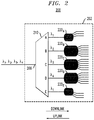
- circuit 200 can be used to implement various respective embodiments of system 100 corresponding to other N and/or K values.
- Circuit 200 includes a passive arrayed-waveguide-grating (AWG) router 210 and five optical power splitters/combiners 220 A -220 E , all implemented on a common planar substrate 202.
- AWG router 210 is illustratively shown as having a single port 208 at its first side and a set of five ports labeled A-E at its second side. Ports A and E are equivalent to each other in terms of their wavelength-routing configuration, with each of them being configured to handle signals with carrier wavelength ⁇ 1 . More specifically, if an optical signal with carrier wavelength ⁇ 1 is applied to port 208, then nominally one half of the transmitted optical power of that signal is routed to port A and nominally one half of the transmitted optical power of that signal is routed to port E.
- AWG router 210 has the dual functionality of a wavelength router and a 3-dB optical power splitter.
- AWG router 210 has the dual functionality of a wavelength router and an optical power combiner.
- Port A is coupled to optical power splitter/combiner 220 A .
- Port E is similarly coupled to optical power splitter/combiner 220 E .
- Each of power splitters/combiners 220 A and 220 E is a (1 ⁇ 3) optical power splitter/combiner. Therefore, for downlink optical signals with carrier wavelength ⁇ 1 , circuit 200 performs one-to-six power splitting. If circuit 200 is deployed in system 100, then the three peripheral ports of optical power splitter/combiner 220 A and the three peripheral ports of optical power splitter/combiner 220 E can be configured, e.g., to direct downlink signals to and receive uplink signals from up to six respective ONUs 160 of ONU group 170 1 (see FIG. 1 ).
- AWG router 210 For optical signals with carrier wavelengths ⁇ 2 , ⁇ 3 , and ⁇ 4 , AWG router 210 has a conventional functionality of a wavelength router only. More specifically, wavelength ⁇ 2 is routed between ports 208 and B; wavelength ⁇ 3 is routed between ports 208 and C; and wavelength ⁇ 4 is routed between ports 208 and D. Ports B-D are coupled to optical power splitters/combiners 220 B -220 D , respectively. Each of optical power splitters/combiners 220 B -220D is a (1 ⁇ 6) optical power splitter/combiner. Therefore, for downlink optical signals with carrier wavelengths ⁇ 2 , ⁇ 3 , and ⁇ 4 , circuit 200 performs one-to-six power splitting for each of said wavelengths.
- each of optical power splitters/combiners 220 B -220 D can be configured, e.g., to direct downlink signals to and receive uplink signals from up to six respective ONUs 160 of ONU groups 170 2 -170 4 , respectively (not explicitly shown in FIG. 1 ).
- different optical power splitters/combiners 220 may be designed to implement different respective splitting ratios for the respective wavelengths.
- circuit 200 in system 100 will become more fully apparent from the description provided below, e.g., in reference to FIGs. 4B-4C .
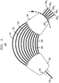
- FIG. 3 schematically shows the layout of a passive AWG router 300 that can be used as AWG router 210 ( FIG. 2 ) according to one embodiment of the invention.
- Passive AWG router 300 has a waveguide 308 at its first side and five waveguides 360 A -360 E at its second side. Waveguides 360 A -360 E are arranged in a planar lateral array. Waveguide 308 in AWG router 300 corresponds to port 208 in AWG router 210. Waveguides 360 A -360 E in AWG router 300 correspond to ports A-E, respectively, in AWG router 210.
- AWG router 300 has two waveguide couplers (also sometimes referred to as star couplers, planar regions, or slabs) 320 and 340 connected by a lateral array of waveguides 330. Different waveguides 330 have different respective lengths, with the lengths generally increasing from the bottom to the top of FIG. 3 .
- a terminus of waveguide 308 is located at an edge 318 of star coupler 320.
- Termini of waveguides 360 A -360 E are located at an edge 338 of star coupler 340.
- the positions, in which the termini of waveguides 360 A -360 E are placed, are selected based on an inventive concept and differ from representative prior-art positions. An explanation of this placement is provided below in reference to FIGs. 4A-4C .
- the cores of waveguides 308, 330, and 360 and the bodies of couplers 320 and 340 are made of the same material, which has a higher refractive index than the cladding material around the cores and the coupler.
- a representative core material is doped silicon oxide.
- FIGs. 4A-4C graphically illustrate methods of selecting waveguide positions in AWG router 300.
- An arrayed waveguide grating such as that used to implement AWG router 300, is usually designed to operate in a relatively high diffraction order, such as about the twentieth or thirtieth diffraction order. If the arrayed waveguide grating is designed for the m -th diffraction order, then it usually has comparable diffraction efficiency for several adjacent orders, such as the ( m -1)-th and the ( m +1)-th, Light corresponding to different adjacent diffraction orders may spatially overlap.
- FIG. 4A graphically shows three representative dispersed-light stripes 402-406 generated by an arrayed waveguide grating at the corresponding edge of its star coupler, such as edge 338 of star coupler 340 in AWG router 300 (see FIG. 3 ).
- Horizontal axis X in FIG. 4A represents the spatial coordinate along the edge of the star coupler, e.g., in the manner indicated by the dashed line in FIG. 3 for edge 338.
- stripes 402-406 are shown as being vertically offset with respect to one another. In reality, stripes 402-406 would be spatially superimposed.
- Stripe 402 corresponds to the ( m -1)-th diffraction order.
- Stripe 404 corresponds to the m -th diffraction order.
- Stripe 406 corresponds to the ( m +1)-th diffraction order.
- Double-headed arrow 410 indicates the width of the grating's Brillouin zone ( W BZ ) .
- This width can be defined as the spatial offset (e.g., measured in microns) between the two instances of the same wavelength, but corresponding to two adjacent diffraction orders, as indicated in FIG. 4A .
- the free spectral range (FSR) of the grating can be defined as the spectral separation (e.g., in Hz or nm) between two spatially superimposed wavelengths corresponding to two adjacent diffraction orders. For example, a spatial location having coordinate x 0 indicated in FIG.
- the FSR value expressed in nm is therefore ⁇ X - ⁇ Y .
- the FSR value expressed in frequency units can be obtained, e.g., by appropriate conversion of nm into Hz.
- a curve 420 in each of these figures shows representative transmission characteristics of the grating as measured along the corresponding edge of its star coupler, such as edge 338 of star coupler 340 in FIG. 3 .
- curve 420 has a bell-like shape.
- the middle portion of curve 420 is relatively flat.
- Vertical dashed lines 422 and 424 mark the locations of the two 3-dB (50%) attenuation points for curve 420.
- the distance between dashed lines 422 and 424 is equal to W BZ , the width of the grating's Brillouin zone as defined above in reference to FIG. 4A , arrow 410.
- Vertical bars 430 A -430 D in FIG. 4B indicate one possible placement of the waveguide termini that meets the above-indicated criteria for an arrayed waveguide grating designed with an FSR that is equal to four inter-channel frequency intervals.
- the filled portions of bars 430 A -430 D indicate the relative optical power received at the respective locations in accordance with transmission curve 420.
- a double-headed arrow 432 indicates the insertion-loss disparity corresponding to this placement of waveguide termini. Note that the insertion-loss disparity indicated by arrow 432 can be slightly decreased if the whole bar comb represented by bars 430 A -430 D is moved slightly to the right so that bars 430 A and 430 D become equidistant from lines 422 and 424, respectively.
- Vertical bars 460 A -460 E in FIG. 4C indicate a placement of the waveguide termini according to one embodiment of the invention. This placement differs from the placement shown in FIG. 4B in that two of the bars, i.e., bars 460 A and 460 E , are placed directly at the BZ edges indicated by dashed lines 422 and 424. Similar to FIG. 4B , the filled portions of bars 460 A -460 E in FIG. 4C indicate the relative optical power received at the respective locations in accordance with transmission curve 420.
- the table located under the abscissa in FIG. 4C lists, by the diffraction order, the wavelengths received at each of the locations corresponding to bars 460 A -460 E .
- both of the locations corresponding to bars 460 A and 460 E receive wavelengths ⁇ 1 and ⁇ 5 . More specifically, the location corresponding to bar 460 A receives wavelengths ⁇ 1 and ⁇ 5 from the m -th and ( m +1)-th diffraction orders, respectively. The location corresponding to bar 460 E receives wavelengths ⁇ 1 and ⁇ 5 from the ( m -1)-th and m -th diffraction orders, respectively.
- the total optical power transmitted by the grating at wavelength ⁇ 1 is represented by the sum of the filled portions of bars 460 A and 460 E and, as such, is very close to the optical power transmitted at wavelength ⁇ 3 represented by the filled portion of bar 460 C .
- wavelength ⁇ 5 A similar observation applies to wavelength ⁇ 5 .
- the resulting effective insertion-loss disparity can be represented by arrows 462, which take into account the fact that the filled portions of bars 460 A and 460 E can be summed up.
- the waveguide configuration of FIG. 4C advantageously provides a smaller insertion-loss disparity than the waveguide configuration of FIG. 4B . It is also worth noting that this reduction in the insertion-loss disparity is achieved without introducing any additional loss to any of the other ports.
- the waveguide configuration of FIG. 4C also provides the 3-dB splitter functionality, which can be used in planar waveguide circuit 200 ( FIG. 2 ) and system 100 ( FIG. 1 ) as already indicated above.
- ONU group 170 2 (not explicitly shown in FIG.
- wavelength ⁇ 2 can be used for downlink signals (as already indicated in FIG. 1 ) and wavelength ⁇ 6 and/or wavelength ⁇ -2 can be used for uplink signals, etc.
- any wavelength ⁇ p ⁇ 2 + p ⁇ FSR, where p is an integer, will satisfy the constraints for being used as a carrier wavelength for uplink signals for channel number 2. This characteristic is important in a WDM-PON system, in which the downstream and upstream wavelengths are assigned to two different wavelength bands. Furthermore, in such a WDM-PON system, the cyclic response of the passive wavelength router significantly reduces the tuning range that the lasers in transmitters 164 ( FIG. 1 ) need to have.
- each transmitter 164 may be tunable over a total range spanning only one FSR of the passive wavelength router and yet be capable to generate one of the accepted carrier wavelengths, regardless of the absolute value of that wavelength. This characteristic greatly reduces the complexity of transmitters 164, which facilitates a concomitant cost reduction as well as a reduction in the power consumption (the latter being particularly important to WDM-PON applications).
- FIG. 5 schematically shows the layout of a circuit portion 500 that can be used to implement the corresponding portion of passive AWG router 300 ( FIG. 3 ) according to one embodiment of the invention.
- the analogous elements in FIGs. 3 and 5 have labels with the same last two digits.
- Dashed lines 522 and 524 mark the boundaries of the grating's Brillouin zone and are analogous to dashed lines 422 and 424, respectively, of FIG. 4C .
- the positions of the termini of waveguides 560 A -560 E at edge 538 correspond to the positions of bars 460 A -460 E , respectively, in FIG. 4C . Therefore, the length of the arc that connects waveguides 560 A and 560 E along edge 538 is W BZ .
- circuit portion 500 advantageously has a relatively small insertion-loss disparity between its wavelength channels and can be used to implement the wavelength-routing configurations that are discussed above in reference to FIG. 4C .
- star coupler 540 has a width, at edge 538, that is larger than the width of the grating's Brillouin zone.
- a representative prior-art star coupler has a width that may be smaller than the grating's Brillouin zone. The latter property is a consequence of the tendency to pack the waveguides as close to the middle portion of the grating's transmission curve as possible, e.g., as already indicated above in reference to FIG. 4B .
- the inter-channel frequency spacing ⁇ F imposed by the specified frequency grid determines the spatial separation a between adjacent waveguides 560 at edge 538.
- the above-described characteristics of an AWG router having circuit portion 500 force a waveguide configuration in which the width ( W BZ ) of the grating's Brillouin zone is approximately equal to 4 a.
- W BZ Na
- prior-art waveguide layouts do not need to satisfy Eq. (2) due to the possible arbitrary positioning of the corresponding waveguides, e.g., as already indicated above in reference to FIG. 4B .
- FIG. 6 graphically illustrates a possible AWG-router design variation according to one embodiment of the invention. More specifically, a curve 620 shown in FIG. 6 is an AWG transmission curve that is analogous to transmission curve 420 shown in FIGs. 4B and 4C . Dashed lines 622 and 624 mark the boundaries of the grating's Brillouin zone and are analogous to dashed lines 422 and 424, respectively, of FIG. 4C .
- Dragone's design compared to the AWG design that produces transmission curve 620 is that the former enables a reduction in the insertion-loss disparity for the waveguides located in the middle of the grating's Brillouin zone.
- both designs have the same W BZ and the same location of the BZ boundaries, as indicated by dashed lines 622 and 624.
- Various embodiments of the present invention e.g., as exemplified by FIG. 4C , can advantageously be used to effectively extend the flat portion of transmission curve 670 substantially all the way to the BZ boundaries.
- various embodiments of the present invention and Dragone's design complement each other and can advantageously be implemented in the same waveguide circuit in a synergistic manner.
- circuit 200 ( FIG. 2 ) has been described as having AWG router 210 coupled to optical power splitters/combiners 220, other circuit configurations are also possible.
- ports A and E of AWG router 210 may both be connected to a single optical power combiner configured to combine downlink signals.
- Such a configuration cancels the power-splitter functionality of AWG router 210 with respect to downlink signals so that the resulting circuit can operate as a conventional AWG router, albeit advantageously having a relatively small insertion-loss disparity between its different wavelength channels.
- AWG router 300 ( FIG. 3 ) has been described as having a single waveguide (e.g., waveguide 308 ) coupled to edge 318 of star coupler 320, embodiments with multiple waveguides coupled to that edge are also possible.
- one or more additional waveguides may be placed along edge 318 so that the resulting AWG router is a cyclic AWG router.
- the two dashed lines next to waveguide 308 in FIG. 3 indicate possible positions of two of such additional waveguides.
- the resulting AWG router can be configured to route a particular carrier wavelength applied to one of the additional optical waveguide to both optical waveguide 360 A and optical waveguide 360 E .
- more waveguides may be added at edge 338, e.g., as indicated by the two dashed lines shown in FIG. 3 next to waveguides 360 A and 360 E , respectively.
- an Echelle grating uses an etched step grating in reflection.
- an Echelle-type router can be integrated on a silica material platform.
- alternative material platforms such as silicon, III-V semiconductor materials, and polymer materials, can also be used.
- Couple refers to any manner known in the art or later developed in which energy is allowed to be transferred between two or more elements, and the interposition of one or more additional elements is contemplated, although not required. Conversely, the terms “directly coupled,” “directly connected,” etc., imply the absence of such additional elements.
- figure numbers and/or figure reference labels in the claims is intended to identify one or more possible embodiments of the claimed subject matter in order to facilitate the interpretation of the claims. Such use is not to be construed as necessarily limiting the scope of those claims to the embodiments shown in the corresponding figures.
Landscapes
- Engineering & Computer Science (AREA)
- Computer Networks & Wireless Communication (AREA)
- Signal Processing (AREA)
- Optical Communication System (AREA)
- Optical Integrated Circuits (AREA)
Claims (11)
- Appareil, comprenant un routeur à réseau sélectif planaire (AWG) passif (par exemple, 210, 300) qui comprend :un premier coupleur optique en étoile (par exemple, 320) ayant un premier guide d'ondes optique (par exemple, 308) couplé à un premier bord (par exemple, 318) de celui-ci et un premier réseau latéral de guides d'ondes optiques (par exemple, 330) couplé à un second bord opposé de celui-ci ; etun second coupleur optique en étoile (par exemple, 340) ayant le premier réseau latéral de guides d'ondes optiques couplé à un premier bord de celui-ci et un second réseau latéral de guides d'ondes optiques (par exemple, 360) couplé à un second bord opposé (par exemple, 338) de celui-ci ; caractérisé en ce que le routeur AWG passif est configuré pour acheminer une première longueur d'onde porteuse appliquée au premier guide d'ondes optique à un premier guide d'ondes optique (par exemple, 360A) du second réseau latéral et à un second guide d'ondes optique (par exemple, 360E) du second réseau latéral, lesdits premier et second guides d'ondes optiques du second réseau latéral étant séparés l'une de l'autre par au moins un autre guide d'ondes optique (par exemple, 360C) positionné entre eux dans ledit second réseau latéral,
le routeur AWG passif est configuré pour transférer des parties environ égales de puissance optique de ladite première longueur d'onde porteuse vers le premier guide d'ondes optique du second réseau latéral et vers le second guide d'ondes optique du second réseau latéral. - Appareil selon la revendication 1, dans lequel :lesdits premier et second guides d'ondes optiques du second réseau latéral sont séparés l'un de l'autre par une distance nominalement égale à la largeur de la zone de Brillouin du routeur AWG passif, ladite distance étant mesurée le long du second bord du second coupleur optique en étoile ; etlesdits premier et second guides d'ondes optiques du second réseau latéral sont équidistants du centre du premier bord.
- Appareil selon la revendication 1, dans lequel lesdits premier et second guides d'ondes optiques du second réseau latéral sont séparés l'un de l'autre par une pluralité de guides d'ondes optiques régulièrement espacés (par exemple, 560B à 560D) positionnés entre eux dans ledit second réseau latéral.
- Appareil selon la revendication 1, dans lequel le second réseau latéral comprend un ou plusieurs guides d'ondes optiques positionnés dans le second réseau latéral en dehors du secteur lié par les premier et second guides d'ondes optiques.
- Appareil selon la revendication 1, dans lequel le second bord du second coupleur optique en étoile a une longueur qui est supérieure à la largeur de la zone de Brillouin du routeur AWG passif.
- Appareil selon la revendication 1, dans lequel le routeur AWG passif est en outre configuré pour acheminer une seconde longueur d'onde porteuse appliquée au premier guide d'ondes optique vers le premier guide d'ondes optique du second réseau latéral et vers le second guide d'ondes optique du second réseau latéral, ladite seconde longueur d'onde porteuse étant décalée par rapport à la première longueur d'onde porteuse selon un intervalle spectral libre du routeur AWG passif exprimé en unités de longueur d'onde.
- Appareil selon la revendication 1, comprenant en outre une pluralité de diviseurs de puissance optique (par exemple, 220), chacun étant couplé à un guide d'ondes respectif parmi les guides d'ondes optiques du second réseau latéral et configuré pour diviser une puissance optique provenant de celui-ci en parties et diriger lesdites parties divisées le long de chemins de propagation respectifs différents.
- Appareil selon la revendication 7, dans lequel :le routeur AWG passif comprend en outre un substrat (par exemple, 202) ayant une surface plane, le premier coupleur optique en étoile, le second coupleur optique en étoile et la pluralité de diviseurs de puissance optique étant mis en oeuvre sur ledit substrat ; etla pluralité de diviseurs de puissance optique comprend :un premier diviseur de puissance optique (par exemple, 220A) couplé au premier guide d'ondes optique du second réseau latéral et configuré pour diviser la puissance optique provenant de celui-ci en k parties divisées, k étant un nombre entier positif supérieur à un ;un deuxième diviseur de puissance optique (par exemple, 220E) couplé au second guide d'ondes optique du second réseau latéral et configuré pour diviser la puissance optique provenant de celui-ci en k parties divisées ; etau moins un troisième diviseur de puissance optique (par exemple, 220c) couplé audit autre guide d'ondes optique du second réseau latéral et configuré pour diviser la puissance optique provenant de celui-ci en 2k parties divisées.
- Appareil selon la revendication 8, comprenant en outre :un premier groupe (par exemple, 1701) d'unités de réseau optique, chacune étant couplée au premier diviseur de puissance optique ou au deuxième diviseur de puissance optique ;un second groupe (par exemple, 170N) d'unités de réseau optique, chacune étant couplée au troisième diviseur de puissance optique ; etun terminal de ligne optique (par exemple, 110) couplé au premier guide d'ondes optique (par exemple, 208) couplé au premier bord du premier coupleur optique en étoile et configuré pour :diffuser, par l'intermédiaire du routeur AWG passif, des signaux optiques ayant la première longueur d'onde porteuse vers le premier groupe d'unités de réseau optique ; etdiffuser, par l'intermédiaire du routeur AWG passif, des signaux optiques ayant une seconde longueur d'onde porteuse vers le second groupe d'unités de réseau optique.
- Appareil selon la revendication 1, dans lequel :le premier coupleur optique en étoile présente en outre un second guide d'ondes optique couplé au premier bord de celui-ci ; etle routeur AWG passif est en outre configuré pour acheminer une seconde longueur d'onde porteuse appliquée au second guide d'ondes optique vers le premier guide d'ondes optique du second réseau latéral et le second guide d'ondes optique du second réseau latéral.
- Appareil selon la revendication 1, dans lequel l'appareil comprend en outre un combineur de puissance optique couplé au premier guide d'ondes optique du second réseau latéral et au second guide d'ondes optique du second réseau latéral et configuré pour combiner une puissance optique provenant desdits premier et second guides d'onde optiques du second réseau latéral.
Applications Claiming Priority (2)
| Application Number | Priority Date | Filing Date | Title |
|---|---|---|---|
| US13/293,787 US8923672B2 (en) | 2011-11-10 | 2011-11-10 | Wavelength router for a passive optical network |
| PCT/US2012/063788 WO2013070654A1 (fr) | 2011-11-10 | 2012-11-07 | Routeur de longueurs d'onde destiné à un réseau optique passif |
Publications (2)
| Publication Number | Publication Date |
|---|---|
| EP2776876A1 EP2776876A1 (fr) | 2014-09-17 |
| EP2776876B1 true EP2776876B1 (fr) | 2018-09-26 |
Family
ID=47215788
Family Applications (1)
| Application Number | Title | Priority Date | Filing Date |
|---|---|---|---|
| EP12788395.7A Active EP2776876B1 (fr) | 2011-11-10 | 2012-11-07 | Routeur de longueurs d'onde destiné à un réseau optique passif |
Country Status (8)
| Country | Link |
|---|---|
| US (1) | US8923672B2 (fr) |
| EP (1) | EP2776876B1 (fr) |
| JP (1) | JP5911592B2 (fr) |
| KR (1) | KR20140074998A (fr) |
| CN (1) | CN103930811B (fr) |
| SG (1) | SG11201402183WA (fr) |
| TW (2) | TW201524147A (fr) |
| WO (1) | WO2013070654A1 (fr) |
Families Citing this family (12)
| Publication number | Priority date | Publication date | Assignee | Title |
|---|---|---|---|---|
| US9720169B2 (en) * | 2013-03-20 | 2017-08-01 | Effect Photonics B.V. | Integrated photonic component and method |
| CN104426739B (zh) * | 2013-09-10 | 2018-08-10 | 上海诺基亚贝尔股份有限公司 | 一种融合城域网和接入网的方法、远程节点以及光线路终端 |
| US9497517B2 (en) | 2014-11-01 | 2016-11-15 | Chin-Tau Lea | ASA: a scalable optical switch |
| CN106605340B (zh) * | 2015-08-18 | 2020-07-10 | 古河电气工业株式会社 | 光半导体装置 |
| US10499125B2 (en) | 2016-12-14 | 2019-12-03 | Chin-Tau Lea | TASA: a TDM ASA-based optical packet switch |
| US20190207702A1 (en) | 2017-12-29 | 2019-07-04 | Nokia Solutions And Networks Oy | Optical receiver |
| US11309973B2 (en) * | 2018-01-31 | 2022-04-19 | Nokia Solutions And Networks Oy | Optical burst monitoring |
| US20190253152A1 (en) | 2018-02-14 | 2019-08-15 | Nokia Solutions And Networks Oy | Multi-rate optical network |
| US11178472B2 (en) | 2018-06-08 | 2021-11-16 | Nokia Solutions And Networks Oy | Monitoring multiple passive optical networks |
| CN111355554B (zh) * | 2018-12-20 | 2023-04-28 | 中兴通讯股份有限公司 | 路由合波器、路由合波方法、波分路由方法及网络系统 |
| US11128498B2 (en) | 2020-02-25 | 2021-09-21 | Nokia Solutions And Networks Oy | Communication-channel tracking aided by reinforcement learning |
| US11616736B2 (en) | 2020-12-17 | 2023-03-28 | Nokia Solutions And Networks Oy | Dynamic resource allocation aided by reinforcement learning |
Citations (1)
| Publication number | Priority date | Publication date | Assignee | Title |
|---|---|---|---|---|
| EP0613263A1 (fr) * | 1993-02-24 | 1994-08-31 | AT&T Corp. | Réseau optique comportant un démultiplexeur de longueur d'onde compact |
Family Cites Families (20)
| Publication number | Priority date | Publication date | Assignee | Title |
|---|---|---|---|---|
| DE69421579T2 (de) * | 1993-08-02 | 2000-06-21 | Nippon Telegraph & Telephone | Integrierter optischer Wellenleiter-Schaltkreis und Test-System für verzweigte optische Leitungen, die ihn benutzen |
| US5600742A (en) * | 1994-09-30 | 1997-02-04 | Lucent Technologies Inc. | Wavelength grating router with output coupler |
| US5680234A (en) * | 1994-10-20 | 1997-10-21 | Lucent Technologies Inc. | Passive optical network with bi-directional optical spectral slicing and loop-back |
| US5864413A (en) * | 1996-02-23 | 1999-01-26 | Lucent Technologies, Inc. | Passive optical network for dense WDM downstream data transmission and upstream data transmission |
| US6014390A (en) * | 1998-01-30 | 2000-01-11 | Lucent Technologies Inc. | Tunable transmitter with Mach-Zehnder modulator |
| US6445847B1 (en) * | 1999-02-24 | 2002-09-03 | Lucent Technologies Inc. | Apparatus and method for achieving a smooth spectral response optical filter |
| US6243402B1 (en) * | 1999-08-31 | 2001-06-05 | Agere Systems Optoelectronics Guardian Corp. | Multi-frequency rapidly tunable laser |
| US6381383B1 (en) | 2000-04-24 | 2002-04-30 | Agere Systems Guardian Corp | Large N×N waveguide grating router |
| US7330659B2 (en) * | 2001-03-02 | 2008-02-12 | Lucent Technologies Inc. | Wavelength filter that operates on sets of wavelength channels |
| US6873766B2 (en) | 2002-04-12 | 2005-03-29 | Corrado P. Dragone | Efficient waveguide arrays with nearly perfect element patterns |
| US7345812B2 (en) | 2003-02-21 | 2008-03-18 | University Of Kansas | Method and apparatus for use of III-nitride wide bandgap semiconductors in optical communications |
| US6956993B2 (en) * | 2003-06-27 | 2005-10-18 | Lucent Technologies Inc. | Arrayed waveguide gratings with improved transmission efficiency |
| US7003198B2 (en) * | 2003-09-09 | 2006-02-21 | Lucent Technologies Inc. | Integrateable band filter using waveguide grating routers |
| US7469079B2 (en) * | 2004-01-26 | 2008-12-23 | The Furukawa Electric Co., Ltd. | Broadband wavelength multiplexing and demultiplexing filter and optical splitter with optical signal multiplexing and demultiplexing function |
| US7149373B2 (en) * | 2004-02-02 | 2006-12-12 | Lucent Technologies Inc. | Active/passive monolithically integrated channel filtering polarization splitter |
| KR100703349B1 (ko) | 2004-11-29 | 2007-04-03 | 삼성전자주식회사 | 파장분할다중 방식의 수동형 광가입자망의 동작 방법 |
| JP4278628B2 (ja) * | 2005-03-30 | 2009-06-17 | 富士通株式会社 | 光伝送システム |
| US7627246B2 (en) * | 2005-07-22 | 2009-12-01 | Novera Optics, Inc. | Wavelength division multiplexing passive optical networks to transport access platforms |
| CN101420285B (zh) | 2007-10-25 | 2012-02-15 | 华为技术有限公司 | 光线路终端、远端节点单元、减少光源数量的方法及系统 |
| PT2332276E (pt) | 2008-09-04 | 2012-03-28 | Ericsson Telefon Ab L M | Redes ópticas passivas |
-
2011
- 2011-11-10 US US13/293,787 patent/US8923672B2/en active Active
-
2012
- 2012-11-05 TW TW104106922A patent/TW201524147A/zh unknown
- 2012-11-05 TW TW101141051A patent/TWI482451B/zh not_active IP Right Cessation
- 2012-11-07 CN CN201280055161.XA patent/CN103930811B/zh active Active
- 2012-11-07 KR KR1020147012444A patent/KR20140074998A/ko not_active Application Discontinuation
- 2012-11-07 SG SG11201402183WA patent/SG11201402183WA/en unknown
- 2012-11-07 EP EP12788395.7A patent/EP2776876B1/fr active Active
- 2012-11-07 JP JP2014541168A patent/JP5911592B2/ja active Active
- 2012-11-07 WO PCT/US2012/063788 patent/WO2013070654A1/fr active Application Filing
Patent Citations (1)
| Publication number | Priority date | Publication date | Assignee | Title |
|---|---|---|---|---|
| EP0613263A1 (fr) * | 1993-02-24 | 1994-08-31 | AT&T Corp. | Réseau optique comportant un démultiplexeur de longueur d'onde compact |
Also Published As
| Publication number | Publication date |
|---|---|
| TW201524147A (zh) | 2015-06-16 |
| WO2013070654A1 (fr) | 2013-05-16 |
| CN103930811B (zh) | 2018-04-03 |
| CN103930811A (zh) | 2014-07-16 |
| US20130121695A1 (en) | 2013-05-16 |
| JP2014534477A (ja) | 2014-12-18 |
| JP5911592B2 (ja) | 2016-04-27 |
| TWI482451B (zh) | 2015-04-21 |
| KR20140074998A (ko) | 2014-06-18 |
| TW201330537A (zh) | 2013-07-16 |
| US8923672B2 (en) | 2014-12-30 |
| SG11201402183WA (en) | 2014-09-26 |
| EP2776876A1 (fr) | 2014-09-17 |
Similar Documents
| Publication | Publication Date | Title |
|---|---|---|
| EP2776876B1 (fr) | Routeur de longueurs d'onde destiné à un réseau optique passif | |
| US10972179B2 (en) | Methods and systems relating to optical networks | |
| EP0985289B1 (fr) | Multiplexage et demultiplexage optiques | |
| US8244133B2 (en) | Optical waveband demultiplexer, optical waveband multiplexer, and optical waveband selective switch | |
| US7321704B2 (en) | Wavelength cross connect with per port performance characteristics | |
| EP1225461B1 (fr) | Multiplexeur et démultiplexeur bidirectionnels basés sur un seul réseau de guides d'onde en échelle | |
| US11101913B2 (en) | Processing of multimode optical signals | |
| US6512864B1 (en) | Optical multiplexer/demultiplexer arrangement for WDM signals having in-band and out-of-band signal components | |
| Niwa et al. | Large port count wavelength routing optical switch consisting of cascaded small-size cyclic arrayed waveguide gratings | |
| WO2011162269A1 (fr) | Multiplexeur/démultiplexeur et procédé de multiplexage/démultiplexage | |
| CN104115047A (zh) | 光板 | |
| Suzuki et al. | Spatial and planar optical circuit | |
| JP5871825B2 (ja) | 波長多重ponシステム | |
| Seno et al. | Wavelength selective switches for SDM photonic nodes based on SPOC platform | |
| GB2595862A (en) | Optical apparatus and associated methods | |
| GB2595863A (en) | Optical apparatus and associated methods | |
| GB2595861A (en) | Optical apparatus and associated methods | |
| Inoue | Recent advances in silica-based PLCs | |
| WO2002098038A1 (fr) | Multiplexeur d'insertion-extraction optique integre utilisant des miroirs de guides d'ondes optiques et multiplexeur/demultiplexeur |
Legal Events
| Date | Code | Title | Description |
|---|---|---|---|
| PUAI | Public reference made under article 153(3) epc to a published international application that has entered the european phase |
Free format text: ORIGINAL CODE: 0009012 |
|
| 17P | Request for examination filed |
Effective date: 20140610 |
|
| AK | Designated contracting states |
Kind code of ref document: A1 Designated state(s): AL AT BE BG CH CY CZ DE DK EE ES FI FR GB GR HR HU IE IS IT LI LT LU LV MC MK MT NL NO PL PT RO RS SE SI SK SM TR |
|
| DAX | Request for extension of the european patent (deleted) | ||
| 17Q | First examination report despatched |
Effective date: 20170511 |
|
| RAP1 | Party data changed (applicant data changed or rights of an application transferred) |
Owner name: ALCATEL LUCENT |
|
| GRAP | Despatch of communication of intention to grant a patent |
Free format text: ORIGINAL CODE: EPIDOSNIGR1 |
|
| RIN1 | Information on inventor provided before grant (corrected) |
Inventor name: BERNASCONI, PIETRO A.G. Inventor name: NEILSON, DAVID T. |
|
| INTG | Intention to grant announced |
Effective date: 20180425 |
|
| GRAS | Grant fee paid |
Free format text: ORIGINAL CODE: EPIDOSNIGR3 |
|
| GRAA | (expected) grant |
Free format text: ORIGINAL CODE: 0009210 |
|
| AK | Designated contracting states |
Kind code of ref document: B1 Designated state(s): AL AT BE BG CH CY CZ DE DK EE ES FI FR GB GR HR HU IE IS IT LI LT LU LV MC MK MT NL NO PL PT RO RS SE SI SK SM TR |
|
| REG | Reference to a national code |
Ref country code: GB Ref legal event code: FG4D |
|
| REG | Reference to a national code |
Ref country code: CH Ref legal event code: EP |
|
| REG | Reference to a national code |
Ref country code: AT Ref legal event code: REF Ref document number: 1046696 Country of ref document: AT Kind code of ref document: T Effective date: 20181015 |
|
| REG | Reference to a national code |
Ref country code: IE Ref legal event code: FG4D |
|
| REG | Reference to a national code |
Ref country code: DE Ref legal event code: R096 Ref document number: 602012051550 Country of ref document: DE |
|
| REG | Reference to a national code |
Ref country code: FR Ref legal event code: PLFP Year of fee payment: 7 |
|
| REG | Reference to a national code |
Ref country code: NL Ref legal event code: MP Effective date: 20180926 |
|
| PG25 | Lapsed in a contracting state [announced via postgrant information from national office to epo] |
Ref country code: FI Free format text: LAPSE BECAUSE OF FAILURE TO SUBMIT A TRANSLATION OF THE DESCRIPTION OR TO PAY THE FEE WITHIN THE PRESCRIBED TIME-LIMIT Effective date: 20180926 Ref country code: BG Free format text: LAPSE BECAUSE OF FAILURE TO SUBMIT A TRANSLATION OF THE DESCRIPTION OR TO PAY THE FEE WITHIN THE PRESCRIBED TIME-LIMIT Effective date: 20181226 Ref country code: GR Free format text: LAPSE BECAUSE OF FAILURE TO SUBMIT A TRANSLATION OF THE DESCRIPTION OR TO PAY THE FEE WITHIN THE PRESCRIBED TIME-LIMIT Effective date: 20181227 Ref country code: NO Free format text: LAPSE BECAUSE OF FAILURE TO SUBMIT A TRANSLATION OF THE DESCRIPTION OR TO PAY THE FEE WITHIN THE PRESCRIBED TIME-LIMIT Effective date: 20181226 Ref country code: SE Free format text: LAPSE BECAUSE OF FAILURE TO SUBMIT A TRANSLATION OF THE DESCRIPTION OR TO PAY THE FEE WITHIN THE PRESCRIBED TIME-LIMIT Effective date: 20180926 Ref country code: RS Free format text: LAPSE BECAUSE OF FAILURE TO SUBMIT A TRANSLATION OF THE DESCRIPTION OR TO PAY THE FEE WITHIN THE PRESCRIBED TIME-LIMIT Effective date: 20180926 Ref country code: LT Free format text: LAPSE BECAUSE OF FAILURE TO SUBMIT A TRANSLATION OF THE DESCRIPTION OR TO PAY THE FEE WITHIN THE PRESCRIBED TIME-LIMIT Effective date: 20180926 |
|
| REG | Reference to a national code |
Ref country code: LT Ref legal event code: MG4D |
|
| PG25 | Lapsed in a contracting state [announced via postgrant information from national office to epo] |
Ref country code: AL Free format text: LAPSE BECAUSE OF FAILURE TO SUBMIT A TRANSLATION OF THE DESCRIPTION OR TO PAY THE FEE WITHIN THE PRESCRIBED TIME-LIMIT Effective date: 20180926 Ref country code: LV Free format text: LAPSE BECAUSE OF FAILURE TO SUBMIT A TRANSLATION OF THE DESCRIPTION OR TO PAY THE FEE WITHIN THE PRESCRIBED TIME-LIMIT Effective date: 20180926 Ref country code: HR Free format text: LAPSE BECAUSE OF FAILURE TO SUBMIT A TRANSLATION OF THE DESCRIPTION OR TO PAY THE FEE WITHIN THE PRESCRIBED TIME-LIMIT Effective date: 20180926 |
|
| REG | Reference to a national code |
Ref country code: AT Ref legal event code: MK05 Ref document number: 1046696 Country of ref document: AT Kind code of ref document: T Effective date: 20180926 |
|
| PG25 | Lapsed in a contracting state [announced via postgrant information from national office to epo] |
Ref country code: ES Free format text: LAPSE BECAUSE OF FAILURE TO SUBMIT A TRANSLATION OF THE DESCRIPTION OR TO PAY THE FEE WITHIN THE PRESCRIBED TIME-LIMIT Effective date: 20180926 Ref country code: PL Free format text: LAPSE BECAUSE OF FAILURE TO SUBMIT A TRANSLATION OF THE DESCRIPTION OR TO PAY THE FEE WITHIN THE PRESCRIBED TIME-LIMIT Effective date: 20180926 Ref country code: IS Free format text: LAPSE BECAUSE OF FAILURE TO SUBMIT A TRANSLATION OF THE DESCRIPTION OR TO PAY THE FEE WITHIN THE PRESCRIBED TIME-LIMIT Effective date: 20190126 Ref country code: AT Free format text: LAPSE BECAUSE OF FAILURE TO SUBMIT A TRANSLATION OF THE DESCRIPTION OR TO PAY THE FEE WITHIN THE PRESCRIBED TIME-LIMIT Effective date: 20180926 Ref country code: IT Free format text: LAPSE BECAUSE OF FAILURE TO SUBMIT A TRANSLATION OF THE DESCRIPTION OR TO PAY THE FEE WITHIN THE PRESCRIBED TIME-LIMIT Effective date: 20180926 Ref country code: CZ Free format text: LAPSE BECAUSE OF FAILURE TO SUBMIT A TRANSLATION OF THE DESCRIPTION OR TO PAY THE FEE WITHIN THE PRESCRIBED TIME-LIMIT Effective date: 20180926 Ref country code: NL Free format text: LAPSE BECAUSE OF FAILURE TO SUBMIT A TRANSLATION OF THE DESCRIPTION OR TO PAY THE FEE WITHIN THE PRESCRIBED TIME-LIMIT Effective date: 20180926 Ref country code: RO Free format text: LAPSE BECAUSE OF FAILURE TO SUBMIT A TRANSLATION OF THE DESCRIPTION OR TO PAY THE FEE WITHIN THE PRESCRIBED TIME-LIMIT Effective date: 20180926 Ref country code: EE Free format text: LAPSE BECAUSE OF FAILURE TO SUBMIT A TRANSLATION OF THE DESCRIPTION OR TO PAY THE FEE WITHIN THE PRESCRIBED TIME-LIMIT Effective date: 20180926 |
|
| PG25 | Lapsed in a contracting state [announced via postgrant information from national office to epo] |
Ref country code: SM Free format text: LAPSE BECAUSE OF FAILURE TO SUBMIT A TRANSLATION OF THE DESCRIPTION OR TO PAY THE FEE WITHIN THE PRESCRIBED TIME-LIMIT Effective date: 20180926 Ref country code: PT Free format text: LAPSE BECAUSE OF FAILURE TO SUBMIT A TRANSLATION OF THE DESCRIPTION OR TO PAY THE FEE WITHIN THE PRESCRIBED TIME-LIMIT Effective date: 20190126 Ref country code: SK Free format text: LAPSE BECAUSE OF FAILURE TO SUBMIT A TRANSLATION OF THE DESCRIPTION OR TO PAY THE FEE WITHIN THE PRESCRIBED TIME-LIMIT Effective date: 20180926 |
|
| REG | Reference to a national code |
Ref country code: DE Ref legal event code: R097 Ref document number: 602012051550 Country of ref document: DE |
|
| REG | Reference to a national code |
Ref country code: CH Ref legal event code: PL |
|
| PG25 | Lapsed in a contracting state [announced via postgrant information from national office to epo] |
Ref country code: DK Free format text: LAPSE BECAUSE OF FAILURE TO SUBMIT A TRANSLATION OF THE DESCRIPTION OR TO PAY THE FEE WITHIN THE PRESCRIBED TIME-LIMIT Effective date: 20180926 Ref country code: LU Free format text: LAPSE BECAUSE OF NON-PAYMENT OF DUE FEES Effective date: 20181107 Ref country code: MC Free format text: LAPSE BECAUSE OF FAILURE TO SUBMIT A TRANSLATION OF THE DESCRIPTION OR TO PAY THE FEE WITHIN THE PRESCRIBED TIME-LIMIT Effective date: 20180926 |
|
| PLBE | No opposition filed within time limit |
Free format text: ORIGINAL CODE: 0009261 |
|
| STAA | Information on the status of an ep patent application or granted ep patent |
Free format text: STATUS: NO OPPOSITION FILED WITHIN TIME LIMIT |
|
| REG | Reference to a national code |
Ref country code: BE Ref legal event code: MM Effective date: 20181130 |
|
| REG | Reference to a national code |
Ref country code: IE Ref legal event code: MM4A |
|
| PG25 | Lapsed in a contracting state [announced via postgrant information from national office to epo] |
Ref country code: LI Free format text: LAPSE BECAUSE OF NON-PAYMENT OF DUE FEES Effective date: 20181130 Ref country code: CH Free format text: LAPSE BECAUSE OF NON-PAYMENT OF DUE FEES Effective date: 20181130 |
|
| 26N | No opposition filed |
Effective date: 20190627 |
|
| PG25 | Lapsed in a contracting state [announced via postgrant information from national office to epo] |
Ref country code: SI Free format text: LAPSE BECAUSE OF FAILURE TO SUBMIT A TRANSLATION OF THE DESCRIPTION OR TO PAY THE FEE WITHIN THE PRESCRIBED TIME-LIMIT Effective date: 20180926 Ref country code: IE Free format text: LAPSE BECAUSE OF NON-PAYMENT OF DUE FEES Effective date: 20181107 |
|
| PG25 | Lapsed in a contracting state [announced via postgrant information from national office to epo] |
Ref country code: BE Free format text: LAPSE BECAUSE OF NON-PAYMENT OF DUE FEES Effective date: 20181130 |
|
| PG25 | Lapsed in a contracting state [announced via postgrant information from national office to epo] |
Ref country code: MT Free format text: LAPSE BECAUSE OF NON-PAYMENT OF DUE FEES Effective date: 20181107 |
|
| PG25 | Lapsed in a contracting state [announced via postgrant information from national office to epo] |
Ref country code: TR Free format text: LAPSE BECAUSE OF FAILURE TO SUBMIT A TRANSLATION OF THE DESCRIPTION OR TO PAY THE FEE WITHIN THE PRESCRIBED TIME-LIMIT Effective date: 20180926 |
|
| PG25 | Lapsed in a contracting state [announced via postgrant information from national office to epo] |
Ref country code: CY Free format text: LAPSE BECAUSE OF FAILURE TO SUBMIT A TRANSLATION OF THE DESCRIPTION OR TO PAY THE FEE WITHIN THE PRESCRIBED TIME-LIMIT Effective date: 20180926 Ref country code: HU Free format text: LAPSE BECAUSE OF FAILURE TO SUBMIT A TRANSLATION OF THE DESCRIPTION OR TO PAY THE FEE WITHIN THE PRESCRIBED TIME-LIMIT; INVALID AB INITIO Effective date: 20121107 Ref country code: MK Free format text: LAPSE BECAUSE OF NON-PAYMENT OF DUE FEES Effective date: 20180926 |
|
| PGFP | Annual fee paid to national office [announced via postgrant information from national office to epo] |
Ref country code: FR Payment date: 20230929 Year of fee payment: 12 |
|
| PGFP | Annual fee paid to national office [announced via postgrant information from national office to epo] |
Ref country code: GB Payment date: 20231006 Year of fee payment: 12 |
|
| PGFP | Annual fee paid to national office [announced via postgrant information from national office to epo] |
Ref country code: DE Payment date: 20230929 Year of fee payment: 12 |