EP2776635B1 - Compactor machine - Google Patents
Compactor machine Download PDFInfo
- Publication number
- EP2776635B1 EP2776635B1 EP12788248.8A EP12788248A EP2776635B1 EP 2776635 B1 EP2776635 B1 EP 2776635B1 EP 12788248 A EP12788248 A EP 12788248A EP 2776635 B1 EP2776635 B1 EP 2776635B1
- Authority
- EP
- European Patent Office
- Prior art keywords
- wheel
- cylindrical
- drum
- compactor machine
- machine according
- Prior art date
- Legal status (The legal status is an assumption and is not a legal conclusion. Google has not performed a legal analysis and makes no representation as to the accuracy of the status listed.)
- Not-in-force
Links
- 238000005096 rolling process Methods 0.000 claims description 24
- 239000000463 material Substances 0.000 claims description 22
- 238000010276 construction Methods 0.000 claims description 13
- 239000012530 fluid Substances 0.000 claims description 7
- 239000002689 soil Substances 0.000 description 7
- 230000007423 decrease Effects 0.000 description 6
- 238000005056 compaction Methods 0.000 description 5
- 230000000694 effects Effects 0.000 description 5
- 230000035515 penetration Effects 0.000 description 4
- 230000008878 coupling Effects 0.000 description 3
- 238000010168 coupling process Methods 0.000 description 3
- 238000005859 coupling reaction Methods 0.000 description 3
- 241001494479 Pecora Species 0.000 description 2
- 239000007788 liquid Substances 0.000 description 2
- 239000007769 metal material Substances 0.000 description 2
- 238000003466 welding Methods 0.000 description 2
- 229910000831 Steel Inorganic materials 0.000 description 1
- 238000006243 chemical reaction Methods 0.000 description 1
- 230000006835 compression Effects 0.000 description 1
- 238000007906 compression Methods 0.000 description 1
- 238000000034 method Methods 0.000 description 1
- 239000010959 steel Substances 0.000 description 1
Images



Classifications
-
- B—PERFORMING OPERATIONS; TRANSPORTING
- B60—VEHICLES IN GENERAL
- B60B—VEHICLE WHEELS; CASTORS; AXLES FOR WHEELS OR CASTORS; INCREASING WHEEL ADHESION
- B60B15/00—Wheels or wheel attachments designed for increasing traction
- B60B15/02—Wheels with spade lugs
-
- B—PERFORMING OPERATIONS; TRANSPORTING
- B60—VEHICLES IN GENERAL
- B60B—VEHICLE WHEELS; CASTORS; AXLES FOR WHEELS OR CASTORS; INCREASING WHEEL ADHESION
- B60B19/00—Wheels not otherwise provided for or having characteristics specified in one of the subgroups of this group
- B60B19/12—Roller-type wheels
-
- E—FIXED CONSTRUCTIONS
- E01—CONSTRUCTION OF ROADS, RAILWAYS, OR BRIDGES
- E01C—CONSTRUCTION OF, OR SURFACES FOR, ROADS, SPORTS GROUNDS, OR THE LIKE; MACHINES OR AUXILIARY TOOLS FOR CONSTRUCTION OR REPAIR
- E01C19/00—Machines, tools or auxiliary devices for preparing or distributing paving materials, for working the placed materials, or for forming, consolidating, or finishing the paving
- E01C19/22—Machines, tools or auxiliary devices for preparing or distributing paving materials, for working the placed materials, or for forming, consolidating, or finishing the paving for consolidating or finishing laid-down unset materials
- E01C19/23—Rollers therefor; Such rollers usable also for compacting soil
- E01C19/236—Construction of the rolling elements, e.g. surface configuration, rolling surface formed by endless track
-
- E—FIXED CONSTRUCTIONS
- E02—HYDRAULIC ENGINEERING; FOUNDATIONS; SOIL SHIFTING
- E02D—FOUNDATIONS; EXCAVATIONS; EMBANKMENTS; UNDERGROUND OR UNDERWATER STRUCTURES
- E02D3/00—Improving or preserving soil or rock, e.g. preserving permafrost soil
- E02D3/02—Improving by compacting
- E02D3/026—Improving by compacting by rolling with rollers usable only for or specially adapted for soil compaction, e.g. sheepsfoot rollers
-
- E—FIXED CONSTRUCTIONS
- E02—HYDRAULIC ENGINEERING; FOUNDATIONS; SOIL SHIFTING
- E02D—FOUNDATIONS; EXCAVATIONS; EMBANKMENTS; UNDERGROUND OR UNDERWATER STRUCTURES
- E02D3/00—Improving or preserving soil or rock, e.g. preserving permafrost soil
- E02D3/02—Improving by compacting
- E02D3/026—Improving by compacting by rolling with rollers usable only for or specially adapted for soil compaction, e.g. sheepsfoot rollers
- E02D3/0265—Wheels specially adapted therefor; Cleats for said wheels
-
- E—FIXED CONSTRUCTIONS
- E02—HYDRAULIC ENGINEERING; FOUNDATIONS; SOIL SHIFTING
- E02D—FOUNDATIONS; EXCAVATIONS; EMBANKMENTS; UNDERGROUND OR UNDERWATER STRUCTURES
- E02D3/00—Improving or preserving soil or rock, e.g. preserving permafrost soil
- E02D3/02—Improving by compacting
- E02D3/026—Improving by compacting by rolling with rollers usable only for or specially adapted for soil compaction, e.g. sheepsfoot rollers
- E02D3/032—Trench rollers
-
- E—FIXED CONSTRUCTIONS
- E02—HYDRAULIC ENGINEERING; FOUNDATIONS; SOIL SHIFTING
- E02D—FOUNDATIONS; EXCAVATIONS; EMBANKMENTS; UNDERGROUND OR UNDERWATER STRUCTURES
- E02D3/00—Improving or preserving soil or rock, e.g. preserving permafrost soil
- E02D3/02—Improving by compacting
- E02D3/046—Improving by compacting by tamping or vibrating, e.g. with auxiliary watering of the soil
Definitions
- the present invention relates to a compactor machine.
- a compactor machine can be used to compact materials for example, but not limited to, refuse at a landfill site, or soil, gravel, etc. at a construction site.
- a conventional compactor machine has wheels and/or rollers with a drum of constant outer diameter.
- the drum may have a smooth exterior or may have teeth (spikes, pads tips, etc.) extending therefrom.
- the teeth are often referred to as "sheep's feet" and aid in compression and traction due to the penetration of the smaller contacting area into the material.
- a compactor machine is known from US3318209A .
- the present invention provides a compactor machine, comprising a plurality of rigid wheels or rollers mounted on axles, each wheel or roller including a rigid drum for contacting material to be compacted, the drum having a profiled outer surface including a first cylindrical portion and a second cylindrical portion, the first cylindrical portion having a larger rolling diameter than the second cylindrical portion, and an inclined portion extending between the first and second cylindrical portions, each wheel or roller including a rigid drum for contacting material to be compacted, the drum having a profiled outer surface including a first cylindrical portion and a second cylindrical portion the first cylindrical portion having a larger rolling diameter than the second cylindrical portion, and an inclined portion extending between the first and second cylindrical portions, wherein the largest diameters of the wheels or rollers mounted on adjacent axles spaced apart along the longitudinal direction of the compactor machine are diametrically overlapping.
- the construction of the wheel/roller is such that the area of contact between the outer surface of the drum and refuse, soil or other material to be compacted varies with the depth of penetration of the wheel into the material.
- the different rolling diameters within the scope of one wheel gives different ground pressures. This means that the pressure applied to the material for compaction varies depending upon the depth of penetration of the wheel.
- the inventors of the present invention have found this to provide more efficient compaction of material.
- the inclined portion of the outer surface of the drum enables infinitely variable pressures. Varying the angle of inclination (with respect to the rotation axis of the wheel) of this inclined portion of the outer surface will have a further effect on the ground pressures which can be obtained.
- One benefit of this wheel/roller design is to allow improved go anywhere mobility - high floatation where needed changing to heavy ground pressure where conditions demand.
- the construction of the wheel/roller also means that the appropriate pressure for a certain volume of material to be compacted is applied by the wheels, without the need to change the wheels.
- Such overlap may be used to remove debris (e.g. refuse or soil) build-up from the wheels and therefore alleviates the need for a scraper system to clean the wheels as used on some vehicles of the prior art.
- debris e.g. refuse or soil
- the angle of the inclined portion of the drum may be set at a range of angles, including but not limited to around 60° to 70° as measured from the wheel axis of rotation.
- the wheel/roller preferably has a centre for coupling to an axle of the machine.
- the centre may be common among various wheel designs, which may include different drums.
- the wheel/roller has a centre for coupling to a specific machine to allow retro-market fitting of the wheel/roller to existing suitable machines.
- the wheel/roller is preferably hollow and may define a sealable interior volume for filling with a ballast fluid.
- the ballast fluid may be used to alter the ground pressure of the wheel/roller as desired.
- the fluid preferably may be drained from the wheel when not required.
- the interior volume may be bounded by the drum and the centre of the wheel.
- the wheel/roller may have a welded metallic construction.
- the metallic material is preferably steel.
- a variety of other metallic and non-metallic materials may alternatively be used, and other wheel construction techniques other than welding may similarly be used.
- the outer surface of the drum may include a plurality of first and/or second cylindrical portions, with a respective inclined portion extending between each first and second cylindrical portions.
- the drum may have further cylindrical portions of a diameter different to the diameter of the first and second cylindrical portions.
- the wheel/roller may include tips (teeth) extending substantially radially outwardly from the first cylindrical portion of the drum.
- the tips knead material to be compacted, for example soil or refuse.
- the tips may be permanently fixed to the-drum. Alternatively, the tips may be removably attached to the drum.
- the wheel/roller may further comprise a cylindrical sleeve carrying the tips, wherein the sleeve is attached to the first cylindrical portion of the drum.
- the sleeve may be interchangeable upon the drum with another sleeve carrying tips selected according to the material to be compacted.
- the sleeve may comprise two or more sections (each defining a half-cylinder) which fit together to form the complete cylindrical sleeve.
- the compactor machine may, for example, have four, six or eight wheels, or a combination of wheels and roller(s).
- the compactor machine may be of the deadweight or vibrating type.
- the machine may be a self-propelling or towed vehicle.
- the compactor machine may have six wheels. This may provide the benefit of increased compounded effort due to a triple rolling effect over the same ground area during one machine pass compared to a conventional four wheel compactor which only has a double rolling effect or in some case only a single rolling effect.
- a compactor vehicle according to an embodiment of the present invention having wheels is indicated generally at 10 in Figure 1 .
- the vehicle 10 in this embodiment is an articulated dump truck (ADT) that has been modified so as to be converted to a compactor.
- Conversion of the six-wheeled ADT vehicle 10 for compactor use includes not only replacement of the wheels for the wheels described herein, but also the inclusion of a front mounted blade, machine under guards to protect from debris getting tangled around any part of the drive train, etc.
- the vehicle may be used to compact refuse for example at a landfill site, and in alternative embodiments the vehicle may be used to compact soil or any other material for compaction.
- the wheels or rollers may be applied to a wide variety of compactor machinery or machinery that can be modified to be used as a compactor, including, but not limited to, any of the following vehicle types: towed deadweight single or double drum units; towed deadweight vibrating single or double drum units; self propelled single drum roller deadweight units; self propelled vibrating single drum units; four wheeled self propelled wheel deadweight rollers; self propelled four wheel vibrating rollers; or self propelled multi-wheel vibrating and deadweight units.
- the vehicle 10 has six wheels; two front wheels 12 and four rear wheels 14. As shown in Figures 1 and 2 , the rear wheels 14 diametrically overlap 16 so as to remove debris, for example refuse or soil, from the adjacent rear wheel which may otherwise build up.
- the provision of six wheels compared to four wheels is advantageous because it improves compaction efficiency by increased compounded effort due to a triple rolling effect over the same ground area.
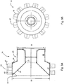
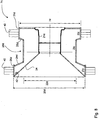
- a wheel according to a first example is indicated generally at 18 in Figures 3A and 3B .
- the wheel 18 includes a drum for contacting material to be compacted, and a centre defining an inner surface 21 for coupling to an axle of the vehicle.
- the wheel has a welded metallic construction.
- the drum is formed such that it has a first cylindrical section 27, a second cylindrical section 29 and a frusto-conical section 24.
- the frusto-conical section 24 is disposed between and adjacent to the first and second cylindrical sections.
- the first cylindrical section 27 has a rolling diameter 20 larger than the rolling diameter 22 of the second cylindrical section.
- the outer surface of the cylindrical sections and frusto-conical section form an outer surface 19 of the drum for contacting material to be compacted, the frusto-conical section forming an inclined surface (or lead angle) from the outer surface 26 of the first cylindrical section to the outer surface 28 of the second cylindrical section.
- the wheel 18 is hollow so that it can be filled with a ballast fluid between the drum and the centre of the wheel.
- the construction of this example is such that when a cross-section of the wheel 18 (as shown in Figure 3A ) is viewed from left to right as shown in the figure (but from right to left in alternative examples) the outer surface 19 has a first portion extending in the longitudinal direction with a constant diameter (i.e. the outer surface 26 of the first cylindrical section 27). The diameter of the outer surface 19 then linearly decreases in the longitudinal direction along the inclined portion (i.e. the outer surface of the frusto-conical section 24) to a second portion of constant diameter (i.e. the outer surface 28 of the second cylindrical section 29).
- the outward facing side of the wheel 18 is formed with a frusto-conical recess such that it has an inclined face 34 that extends from an edge of the outer surface of the first cylindrical section to an edge of the inner surface 21 of the centre of the wheel 18.
- the recess may extend to any position nearer the centre of the wheel than the outer surface, and does not necessarily extend to the inner surface.
- a plug 42 is provided in the inclined face 34 of the recess to fill (and drain) the hollow wheel with ballast fluid.
- the wheel defines a sealable interior volume between the drum and the centre of the wheel.
- the amount of liquid can be chosen to suit a given application.
- the fluid will be a liquid which will not freeze in cold ambient temperatures.
- the plug may be provided in any suitable position, or multiple plugs may be provided.
- Tips (teeth) 40 are arranged in two rows around the perimeter of the wheel and extend substantially radially outwardly from the outer surface of the first cylindrical section 27 of the drum. Alternatively, the tips may be inclined (at a small angle) either towards or away from the direction of forward rotation of the wheel, or towards or away from the vehicle body.
- the tips are of the "sheep's feet" type, but may alternatively take any suitable form.
- the tips 40 are permanently fixed to the drum, e.g. by welding. Alternatively, the tips may be removably attached to the drum, e.g. by bolting.
- an alternative tip 40b is shown.
- the tip 40b protrudes from a base 70 that is attachable to a wheel or a further component that is attachable to a wheel, an example of which is described later.
- the tip 40b is shaped in the form of a cross. The sides of the tip are inclined and the edges 68, that in use initially contact the ground, are chamfered.
- the wheel/roller may not comprise tips, in some such cases the exterior surface of the wheel/roller may be corrugated with any suitable additional pattern.
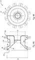
- a wheel according to a second example is indicated generally at 50 in Figures 4A and 4B . Only the differences between the wheel 50 and the wheel 18 will be described in the following and like reference numerals have been used to denote like parts.
- the drum of the wheel 50 is formed such that it has a first cylindrical section 27a, a second cylindrical section 29a, a third cylindrical section 33 and two frusto-conical sections 24a, 25.
- the second cylindrical section 29a is positioned between the first and the third cylindrical sections 27a, 33.
- One of the frusto-conical sections 24a is positioned between and adjacent to the first and second cylindrical sections 27a, 29a and the other frusto-conical section 25 is positioned between and adjacent to the second and third cylindrical sections 29a, 33.
- the outer surface of the cylindrical sections and frusto-conical sections form an outer surface 19a of the drum for contacting material to be compacted, the frusto-conical section 24a forming an inclined surface (or lead angle) from the outer surface 26a of the first cylindrical section 27a to the outer surface 28a of the second cylindrical section, and the frusto-conical section 25 forming an inclined surface (or lead angle) from the outer surface 28a of the second cylindrical section 29a to the outer surface 31 of the third cylindrical section 33.
- the rolling diameters 20a of the first and the third cylindrical sections are equal and larger than the rolling diameter 22a of the second cylindrical section.
- the construction of this example of the wheel is such that when a cross-section of the wheel 50 (as shown in Figure 4A ) is viewed from left to right as shown in the figure (but from right to left in alternative examples) the outer surface 19a has a first portion extending in the longitudinal direction with a constant diameter (i.e. the outer surface 26a of the first cylindrical section 27a).
- the diameter of the outer surface 19a then linearly decreases in the longitudinal direction along a first inclined portion (i.e. the outer surface of the frusto-conical section 24a) to a second portion of constant diameter (i.e. the outer surface 28a of the second cylindrical section 29a).
- the diameter of the outer surface 19a then linearly increases in the longitudinal direction along a second inclined portion (i.e. the outer surface of the frusto-conical section 25) to a third portion of constant diameter (i.e. the outer surface 31 of the third cylindrical section 33).
- the two rows of tips (teeth) 40 are arranged around the perimeter of the wheel with one row extending substantially radially from the outer surface of the first cylindrical section 27a and the other row extending radially from the outer surface of the third cylindrical section 33.
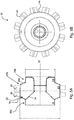
- a wheel according to a third example is indicated generally at 52 in Figures 5A and 5B . Only the differences between the wheel 52 and the wheel 18 will be described in the following and like reference numerals have been used to denote like parts.
- the drum of the wheel 52 is formed such that it has a first cylindrical section 27b, a second cylindrical section 29b, a third cylindrical section 35 and two frusto-conical sections 24b, 54.
- One of the frusto-conical sections 54 is positioned between and adjacent to first and third cylindrical sections 27b, 35 and the other frusto-conical section 24b is positioned between and adjacent to the first and second cylindrical sections 27b, 29b.
- the rolling diameter 20b of the first cylindrical section 27b is larger than the rolling diameter 22b of the second and third cylindrical sections 29b, 35.
- the outer surface of the cylindrical sections and frusto-conical sections form an outer surface 19b of the wheel for contacting material to be compacted.
- One frusto-conical section 54 forms an inclined surface (or lead angle) from an outer surface 35b of the third cylindrical section 35 to the outer surface 26b of the first cylindrical section 27b
- the other frusto-conical section 24b forms an inclined surface (or lead angle) from the outer surface 26b of the first cylindrical section 27b to the outer surface 28b of the second cylindrical section 29b.
- the construction of this example of the wheel is such that when a cross-section of the wheel 52 (as shown in Figure 5A ) is viewed from left to right as shown in the figure (but from right to left in alternative examples) the outer surface 19b has a first portion extending in the longitudinal direction with a constant diameter (i.e. the outer surface 35b of the third cylindrical section 35).
- the diameter of the outer surface 19b then increases linearly in the longitudinal direction along a first inclined portion (i.e. the outer surface of the frusto-conical section 54) to a second portion of constant diameter (i.e. the outer surface 26b of the first cylindrical section 27b).
- the diameter of the outer surface 19b then linearly decreases in the longitudinal direction along a second inclined portion (i.e. the outer surface of the frusto-conical section 24b) to a third portion of constant diameter (i.e. the outer surface 28b of the second cylindrical section 29b).
- the two rows of tips (teeth) 40 are arranged around the perimeter of the wheel and extend substantially radially from the outer surface 26b of the first cylindrical section 27b.
- the wheels 50, 52 which make up each set of rear wheels 14 of the vehicle 10 are diametrically overlapping.
- the tips 40 of the wheels 50 diametrically overlap with the tips 40 of the wheels 52.
- Such overlap may be used to remove debris (e.g. refuse or soil) build-up from the wheels and therefore alleviates the need for a scraper system to clean the wheels as used on some vehicles of the prior art.
- the tips 40 of the wheels 52 are arranged to sweep close to the smooth outer surface 28a of the smaller diameter second cylindrical section 29a of the wheels 50.
- the tips 40 of the wheels 50 are arranged to sweep close to the smooth outer surfaces 28b and 35b of the smaller diameter second and third cylindrical sections 29n and 25 of the wheels 52.
- a wheel according to a fourth example is indicated generally at 71 in Figure 8 . Only the differences between the wheel 71 and the wheel 18 will be described in the following and like reference numerals have been used to denote like parts.
- the drum of the wheel 71 is formed such that it has a first cylindrical section 27d, a second cylindrical section 29d, a third cylindrical section 33d and two frusto-conical sections 24d, 25d.
- the second cylindrical section 29d is positioned between the first and the third cylindrical sections 27d, 33d.
- One of the frusto-conical sections 24d is positioned between and adjacent to the first and second cylindrical sections 27d, 29d and the other frusto-conical section 25d is positioned between and adjacent to the second and third cylindrical sections 29d, 33d.
- the outer surface of the cylindrical sections and frusto-conical sections form an outer surface of the drum for contacting material to be compacted, the frusto-conical section 24d forming an inclined surface (or lead angle) from the outer surface 26d of the first cylindrical section 27d to the outer surface 28d of the second cylindrical section 29d, and the frusto-conical section 25d forming an inclined surface (or lead angle) from the outer surface 28d of the second cylindrical section 29d to the outer surface 31d of the third cylindrical section 33d.
- the rolling diameters 20d of the first cylindrical section is larger than the rolling diameter 74 of the third cylindrical section, and the rolling diameter of the third cylindrical section is larger than the rolling diameter 22d of the second cylindrical section.
- the construction of this example of the wheel is such that when a cross-section of the wheel 71 is viewed from left to right as shown in Figure 8 (but from right to left in alternative examples) the outer surface has a first portion extending in the longitudinal direction with a constant diameter (i.e. the outer surface 26d of the first cylindrical section 27d).
- the diameter of the outer surface then linearly decreases in the longitudinal direction along a first inclined portion (i.e. the outer surface of the frusto-conical section 24d) to a second portion of constant diameter (i.e. the outer surface 28d of the second cylindrical section 29d).
- the diameter of the outer surface then linearly increases in the longitudinal direction along a second inclined portion (i.e. the outer surface of the frusto-conical section 25d) to a third portion of constant diameter (i.e. the outer surface 31d of the third cylindrical section 33d).
- the two rows of tips (teeth) 40 are arranged around the perimeter of the wheel with one row extending substantially radially from the outer surface of the first cylindrical section 27d and the other row extending radially from the outer surface of the third cylindrical section 33d.
- a wheel according to a fifth example is indicated generally at 72 in Figure 9 . Only the differences between the wheel 72 and the wheel 18 will be described in the following and like reference numerals have been used to denote like parts.
- the drum of the wheel 72 is formed such that it has a first cylindrical section 27e, a second cylindrical section 82, a third cylindrical section 84, and a fourth cylindrical section 33e and three frusto-conical sections 24e, 25e and 83.
- the second cylindrical section 82 is positioned between the first and the third cylindrical sections 27e, 84, and the third cylindrical section 84 is positioned between the second and fourth cylindrical sections 82 and 33e.
- One of the frusto-conical sections 24e is positioned between and adjacent to the first and second cylindrical sections 27e, 82, another of the frusto-conical sections 83 is positioned between and adjacent to the second and third cylindrical sections 82, 84, and the other frusto-conical section 25e is positioned between and adjacent to the third and fourth cylindrical sections 84, 33e.
- the outer surface of the cylindrical sections and frusto-conical sections form an outer surface of the drum for contacting material to be compacted, the frusto-conical section 24e forming an inclined surface (or lead angle) from the outer surface 26e of the first cylindrical section 27e to the outer surface 82e of the second cylindrical section 82, the frusto-conical section 83 forming an inclined surface (or lead angle) from the outer surface 82e of the second cylindrical section 82 to the outer surface 84e of the third cylindrical section 84, and the frusto-conical section 25e forming an inclined surface (or lead angle) from the outer surface 84e of the third cylindrical section 84 to the outer surface 31 e of the fourth cylindrical section 33e.
- the rolling diameters 20e of the first cylindrical section is larger than the rolling diameter 80 of the fourth cylindrical section
- the rolling diameter 80 of the fourth cylindrical section is larger than the rolling diameter 78 of the second cylindrical section
- the rolling diameter 78 of the second cylindrical section is larger than the rolling diameter 76 of the third cylindrical section.
- the construction of this example of the wheel is such that when a cross-section of the wheel 72 is viewed from left to right as shown in Figure 8 (but from right to left in alternative examples) the outer surface has a first portion extending in the longitudinal direction with a constant diameter (i.e. the outer surface 26e of the first cylindrical section 27e). The diameter of the outer surface then linearly decreases in the longitudinal direction along a first inclined portion (i.e. the outer surface of the frusto-conical section 24e) to a second portion of constant diameter (i.e. the outer surface 82e of the second cylindrical section 82). The diameter of the outer surface then linearly decreases in the longitudinal direction along a second inclined portion (i.e.
- the outer surface of the frusto-conical section 83 to a second portion of constant diameter (i.e. the outer surface 84e of the third cylindrical section 84).
- the diameter of the outer surface then linearly increases in the longitudinal direction along a third inclined portion (i.e. the outer surface of the frusto-conical section 25e) to a fourth portion of constant diameter (i.e. the outer surface 31e of the third cylindrical section 33e).
- the two rows of tips (teeth) 40 are arranged around the perimeter of the wheel with one row extending substantially radially from the outer surface of the first cylindrical section 27e and the other row extending radially from the outer surface of the fourth cylindrical section 33e.
- the previously described examples advantageously provide a wheel having a construction such that the area of contact of the wheel with material to be compacted varies with the depth of penetration of the wheel into said material.
- the inventors of the present invention have found this to improve the efficiency of compaction.
- Such a profiled outer surface also means that the wheels apply an appropriate pressure for a given ground hardness without the need to change the wheel.
- the larger diameter cylindrical surfaces of the wheel may be fitted with a set of interchangeable "feet", which allow different wheel tips to be introduced quickly and cost effectively simply by replacing the wheel feet as opposed to stocking and changing the complete wheel.
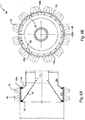
- Figure 6A and 6B illustrates an example of a set of "feet" 56 attached to a wheel.
- the set of feet 56 in this example comprises two similar semi-circular cylindrical sleeve sections 58a, 58b carrying the tips 40.
- the sleeve sections 58a, 58b have an outer surface 19c for contacting the ground and an inner surface 62 for contact with a smooth cylindrical outer surface of the wheel.
- the wheel shown in Figure 6A and 6B has a first cylindrical section 27c and a second cylindrical section 29c, the first cylindrical section 27c having a greater diameter than the second cylindrical section 29c.
- the sleeve sections 58a, 58b are connected to the first cylindrical section by fasteners 64 spaced around the two circumferential edges of the first cylindrical section.
- the two sections 58a, 58b spaced apart by a distance 66 that is set so as to permit easy changing of the sleeve sections 58a, 58b.
Landscapes
- Engineering & Computer Science (AREA)
- Structural Engineering (AREA)
- Life Sciences & Earth Sciences (AREA)
- Civil Engineering (AREA)
- Paleontology (AREA)
- Soil Sciences (AREA)
- General Life Sciences & Earth Sciences (AREA)
- Mining & Mineral Resources (AREA)
- Environmental & Geological Engineering (AREA)
- Agronomy & Crop Science (AREA)
- General Engineering & Computer Science (AREA)
- Mechanical Engineering (AREA)
- Architecture (AREA)
- Investigation Of Foundation Soil And Reinforcement Of Foundation Soil By Compacting Or Drainage (AREA)
- Road Paving Machines (AREA)
- Processing Of Solid Wastes (AREA)
- Soil Working Implements (AREA)
Description
- The present invention relates to a compactor machine.
- A compactor machine can be used to compact materials for example, but not limited to, refuse at a landfill site, or soil, gravel, etc. at a construction site.
- A conventional compactor machine has wheels and/or rollers with a drum of constant outer diameter. The drum may have a smooth exterior or may have teeth (spikes, pads tips, etc.) extending therefrom. The teeth are often referred to as "sheep's feet" and aid in compression and traction due to the penetration of the smaller contacting area into the material.
- A compactor machine is known from
US3318209A . - The present invention provides a compactor machine, comprising a plurality of rigid wheels or rollers mounted on axles, each wheel or roller including a rigid drum for contacting material to be compacted, the drum having a profiled outer surface including a first cylindrical portion and a second cylindrical portion, the first cylindrical portion having a larger rolling diameter than the second cylindrical portion, and an inclined portion extending between the first and second cylindrical portions, each wheel or roller including a rigid drum for contacting material to be compacted, the drum having a profiled outer surface including a first cylindrical portion and a second cylindrical portion the first cylindrical portion having a larger rolling diameter than the second cylindrical portion, and an inclined portion extending between the first and second cylindrical portions, wherein the largest diameters of the wheels or rollers mounted on adjacent axles spaced apart along the longitudinal direction of the compactor machine are diametrically overlapping.
- The construction of the wheel/roller is such that the area of contact between the outer surface of the drum and refuse, soil or other material to be compacted varies with the depth of penetration of the wheel into the material. The different rolling diameters within the scope of one wheel gives different ground pressures. This means that the pressure applied to the material for compaction varies depending upon the depth of penetration of the wheel. The inventors of the present invention have found this to provide more efficient compaction of material. The inclined portion of the outer surface of the drum enables infinitely variable pressures. Varying the angle of inclination (with respect to the rotation axis of the wheel) of this inclined portion of the outer surface will have a further effect on the ground pressures which can be obtained. One benefit of this wheel/roller design is to allow improved go anywhere mobility - high floatation where needed changing to heavy ground pressure where conditions demand.
- The construction of the wheel/roller also means that the appropriate pressure for a certain volume of material to be compacted is applied by the wheels, without the need to change the wheels.
- Advantageously such overlap may be used to remove debris (e.g. refuse or soil) build-up from the wheels and therefore alleviates the need for a scraper system to clean the wheels as used on some vehicles of the prior art.
- The angle of the inclined portion of the drum may be set at a range of angles, including but not limited to around 60° to 70° as measured from the wheel axis of rotation.
- The wheel/roller preferably has a centre for coupling to an axle of the machine. The centre may be common among various wheel designs, which may include different drums. Alternatively, the wheel/roller has a centre for coupling to a specific machine to allow retro-market fitting of the wheel/roller to existing suitable machines.
- The wheel/roller is preferably hollow and may define a sealable interior volume for filling with a ballast fluid. The ballast fluid may be used to alter the ground pressure of the wheel/roller as desired. The fluid preferably may be drained from the wheel when not required. The interior volume may be bounded by the drum and the centre of the wheel.
- The wheel/roller may have a welded metallic construction. The metallic material is preferably steel. However, a variety of other metallic and non-metallic materials may alternatively be used, and other wheel construction techniques other than welding may similarly be used.
- The outer surface of the drum may include a plurality of first and/or second cylindrical portions, with a respective inclined portion extending between each first and second cylindrical portions.
- Optionally, the drum may have further cylindrical portions of a diameter different to the diameter of the first and second cylindrical portions.
- The wheel/roller may include tips (teeth) extending substantially radially outwardly from the first cylindrical portion of the drum. In use, the tips knead material to be compacted, for example soil or refuse.
- The tips may be permanently fixed to the-drum. Alternatively, the tips may be removably attached to the drum.
- The wheel/roller may further comprise a cylindrical sleeve carrying the tips, wherein the sleeve is attached to the first cylindrical portion of the drum. The sleeve may be interchangeable upon the drum with another sleeve carrying tips selected according to the material to be compacted. The sleeve may comprise two or more sections (each defining a half-cylinder) which fit together to form the complete cylindrical sleeve.
- The compactor machine may, for example, have four, six or eight wheels, or a combination of wheels and roller(s).
- The compactor machine may be of the deadweight or vibrating type. The machine may be a self-propelling or towed vehicle.
- In one embodiment, the compactor machine may have six wheels. This may provide the benefit of increased compounded effort due to a triple rolling effect over the same ground area during one machine pass compared to a conventional four wheel compactor which only has a double rolling effect or in some case only a single rolling effect.
- Embodiments of the invention will now be described with reference to the accompanying drawings, in which:
-
Figure 1 shows a side view of an example of a landfill compactor vehicle according to the present invention having six wheels; -
Figure 2 shows a plan view of the vehicle ofFigure 1 ; -
Figure 3A shows a cross-sectional side view of a front wheel of the vehicle according to a first example; -
Figure 3B shows a side view of the wheel shown inFigure 3A ; -
Figure 4A shows a cross-sectional side view of a rear wheel of the vehicle according to a second example; -
Figure 4B shows a side view of the wheel shown inFigure 4A ; -
Figure 5A shows a cross-sectional side view of a rear wheel of the vehicle according to a third example; -
Figure 5B shows a side view of the wheel shown inFigure 5A ; -
Figure 6 shows a side view of a detachable foot in two halves for the wheel according to another example; -
Figure 7A shows a side view of a tip suitable for use on the wheel or detachable feet of any one ofFigures 3 to 6 ; -
Figure 7B shows a front view of the tip ofFigure 7A ; -
Figure 7C shows a plan view of the tip ofFigures 7A and 7B ; -
Figure 8 shows a cross-sectional side view of a wheel according to fourth example; and -
Figure 9 shows a cross-sectional side view of a wheel according to a fifth example. - A compactor vehicle according to an embodiment of the present invention, having wheels is indicated generally at 10 in
Figure 1 . Thevehicle 10 in this embodiment is an articulated dump truck (ADT) that has been modified so as to be converted to a compactor. Conversion of the six-wheeled ADT vehicle 10 for compactor use includes not only replacement of the wheels for the wheels described herein, but also the inclusion of a front mounted blade, machine under guards to protect from debris getting tangled around any part of the drive train, etc. - In some embodiments the vehicle may be used to compact refuse for example at a landfill site, and in alternative embodiments the vehicle may be used to compact soil or any other material for compaction.
- The wheels or rollers may be applied to a wide variety of compactor machinery or machinery that can be modified to be used as a compactor, including, but not limited to, any of the following vehicle types: towed deadweight single or double drum units; towed deadweight vibrating single or double drum units; self propelled single drum roller deadweight units; self propelled vibrating single drum units; four wheeled self propelled wheel deadweight rollers; self propelled four wheel vibrating rollers; or self propelled multi-wheel vibrating and deadweight units.
- In this example, the
vehicle 10 has six wheels; twofront wheels 12 and fourrear wheels 14. As shown inFigures 1 and 2 , therear wheels 14 diametrically overlap 16 so as to remove debris, for example refuse or soil, from the adjacent rear wheel which may otherwise build up. The provision of six wheels compared to four wheels (typical of conventional landfill compactor vehicles) is advantageous because it improves compaction efficiency by increased compounded effort due to a triple rolling effect over the same ground area. - A wheel according to a first example is indicated generally at 18 in
Figures 3A and 3B . Thewheel 18 includes a drum for contacting material to be compacted, and a centre defining aninner surface 21 for coupling to an axle of the vehicle. The wheel has a welded metallic construction. - The drum is formed such that it has a first
cylindrical section 27, a secondcylindrical section 29 and a frusto-conical section 24. The frusto-conical section 24 is disposed between and adjacent to the first and second cylindrical sections. The firstcylindrical section 27 has a rollingdiameter 20 larger than the rollingdiameter 22 of the second cylindrical section. The outer surface of the cylindrical sections and frusto-conical section form anouter surface 19 of the drum for contacting material to be compacted, the frusto-conical section forming an inclined surface (or lead angle) from theouter surface 26 of the first cylindrical section to theouter surface 28 of the second cylindrical section. Thewheel 18 is hollow so that it can be filled with a ballast fluid between the drum and the centre of the wheel. - The construction of this example is such that when a cross-section of the wheel 18 (as shown in
Figure 3A ) is viewed from left to right as shown in the figure (but from right to left in alternative examples) theouter surface 19 has a first portion extending in the longitudinal direction with a constant diameter (i.e. theouter surface 26 of the first cylindrical section 27). The diameter of theouter surface 19 then linearly decreases in the longitudinal direction along the inclined portion (i.e. the outer surface of the frusto-conical section 24) to a second portion of constant diameter (i.e. theouter surface 28 of the second cylindrical section 29). - The outward facing side of the
wheel 18 is formed with a frusto-conical recess such that it has aninclined face 34 that extends from an edge of the outer surface of the first cylindrical section to an edge of theinner surface 21 of the centre of thewheel 18. In other examples the recess may extend to any position nearer the centre of the wheel than the outer surface, and does not necessarily extend to the inner surface. - A
plug 42 is provided in theinclined face 34 of the recess to fill (and drain) the hollow wheel with ballast fluid. The wheel defines a sealable interior volume between the drum and the centre of the wheel. The amount of liquid can be chosen to suit a given application. Preferably, the fluid will be a liquid which will not freeze in cold ambient temperatures. In other examples the plug may be provided in any suitable position, or multiple plugs may be provided. - Tips (teeth) 40 are arranged in two rows around the perimeter of the wheel and extend substantially radially outwardly from the outer surface of the first
cylindrical section 27 of the drum. Alternatively, the tips may be inclined (at a small angle) either towards or away from the direction of forward rotation of the wheel, or towards or away from the vehicle body. The tips are of the "sheep's feet" type, but may alternatively take any suitable form. In this example thetips 40 are permanently fixed to the drum, e.g. by welding. Alternatively, the tips may be removably attached to the drum, e.g. by bolting. - Referring to
Figures 7A to 7C , an alternative tip 40b is shown. In this alternative example the tip 40b protrudes from a base 70 that is attachable to a wheel or a further component that is attachable to a wheel, an example of which is described later. The tip 40b is shaped in the form of a cross. The sides of the tip are inclined and theedges 68, that in use initially contact the ground, are chamfered. - In alternative examples the wheel/roller may not comprise tips, in some such cases the exterior surface of the wheel/roller may be corrugated with any suitable additional pattern.
- A wheel according to a second example is indicated generally at 50 in
Figures 4A and 4B . Only the differences between thewheel 50 and thewheel 18 will be described in the following and like reference numerals have been used to denote like parts. - The drum of the
wheel 50 is formed such that it has a firstcylindrical section 27a, a secondcylindrical section 29a, a thirdcylindrical section 33 and two frusto-conical sections cylindrical section 29a is positioned between the first and the thirdcylindrical sections conical sections 24a is positioned between and adjacent to the first and secondcylindrical sections conical section 25 is positioned between and adjacent to the second and thirdcylindrical sections - The outer surface of the cylindrical sections and frusto-conical sections form an outer surface 19a of the drum for contacting material to be compacted, the frusto-
conical section 24a forming an inclined surface (or lead angle) from the outer surface 26a of the firstcylindrical section 27a to theouter surface 28a of the second cylindrical section, and the frusto-conical section 25 forming an inclined surface (or lead angle) from theouter surface 28a of the secondcylindrical section 29a to the outer surface 31 of the thirdcylindrical section 33. - The rolling diameters 20a of the first and the third cylindrical sections are equal and larger than the rolling diameter 22a of the second cylindrical section.
- The construction of this example of the wheel is such that when a cross-section of the wheel 50 (as shown in
Figure 4A ) is viewed from left to right as shown in the figure (but from right to left in alternative examples) the outer surface 19a has a first portion extending in the longitudinal direction with a constant diameter (i.e. the outer surface 26a of the firstcylindrical section 27a). The diameter of the outer surface 19a then linearly decreases in the longitudinal direction along a first inclined portion (i.e. the outer surface of the frusto-conical section 24a) to a second portion of constant diameter (i.e. theouter surface 28a of the secondcylindrical section 29a). The diameter of the outer surface 19a then linearly increases in the longitudinal direction along a second inclined portion (i.e. the outer surface of the frusto-conical section 25) to a third portion of constant diameter (i.e. the outer surface 31 of the third cylindrical section 33). - In this example the two rows of tips (teeth) 40 are arranged around the perimeter of the wheel with one row extending substantially radially from the outer surface of the first
cylindrical section 27a and the other row extending radially from the outer surface of the thirdcylindrical section 33. - A wheel according to a third example is indicated generally at 52 in
Figures 5A and 5B . Only the differences between thewheel 52 and thewheel 18 will be described in the following and like reference numerals have been used to denote like parts. - The drum of the
wheel 52 is formed such that it has a firstcylindrical section 27b, a secondcylindrical section 29b, a thirdcylindrical section 35 and two frusto-conical sections conical sections 54 is positioned between and adjacent to first and thirdcylindrical sections conical section 24b is positioned between and adjacent to the first and secondcylindrical sections - The rolling diameter 20b of the first
cylindrical section 27b is larger than the rolling diameter 22b of the second and thirdcylindrical sections - The outer surface of the cylindrical sections and frusto-conical sections form an
outer surface 19b of the wheel for contacting material to be compacted. One frusto-conical section 54 forms an inclined surface (or lead angle) from anouter surface 35b of the thirdcylindrical section 35 to theouter surface 26b of the firstcylindrical section 27b, and the other frusto-conical section 24b forms an inclined surface (or lead angle) from theouter surface 26b of the firstcylindrical section 27b to theouter surface 28b of the secondcylindrical section 29b. - The construction of this example of the wheel is such that when a cross-section of the wheel 52 (as shown in
Figure 5A ) is viewed from left to right as shown in the figure (but from right to left in alternative examples) theouter surface 19b has a first portion extending in the longitudinal direction with a constant diameter (i.e. theouter surface 35b of the third cylindrical section 35). The diameter of theouter surface 19b then increases linearly in the longitudinal direction along a first inclined portion (i.e. the outer surface of the frusto-conical section 54) to a second portion of constant diameter (i.e. theouter surface 26b of the firstcylindrical section 27b). The diameter of theouter surface 19b then linearly decreases in the longitudinal direction along a second inclined portion (i.e. the outer surface of the frusto-conical section 24b) to a third portion of constant diameter (i.e. theouter surface 28b of the secondcylindrical section 29b). - In this example the two rows of tips (teeth) 40 are arranged around the perimeter of the wheel and extend substantially radially from the
outer surface 26b of the firstcylindrical section 27b. - Returning to
Figures 1 and 2 , it can be seen that thewheels rear wheels 14 of thevehicle 10 are diametrically overlapping. In particular thetips 40 of thewheels 50 diametrically overlap with thetips 40 of thewheels 52. Advantageously such overlap may be used to remove debris (e.g. refuse or soil) build-up from the wheels and therefore alleviates the need for a scraper system to clean the wheels as used on some vehicles of the prior art. As can be seen fromFigure 2 , thetips 40 of thewheels 52 are arranged to sweep close to the smoothouter surface 28a of the smaller diameter secondcylindrical section 29a of thewheels 50. Similarly, thetips 40 of thewheels 50 are arranged to sweep close to the smoothouter surfaces cylindrical sections 29n and 25 of thewheels 52. - A wheel according to a fourth example is indicated generally at 71 in
Figure 8 . Only the differences between thewheel 71 and thewheel 18 will be described in the following and like reference numerals have been used to denote like parts. - The drum of the
wheel 71 is formed such that it has a firstcylindrical section 27d, a secondcylindrical section 29d, a thirdcylindrical section 33d and two frusto-conical sections cylindrical section 29d is positioned between the first and the thirdcylindrical sections conical sections 24d is positioned between and adjacent to the first and secondcylindrical sections conical section 25d is positioned between and adjacent to the second and thirdcylindrical sections - The outer surface of the cylindrical sections and frusto-conical sections form an outer surface of the drum for contacting material to be compacted, the frusto-
conical section 24d forming an inclined surface (or lead angle) from theouter surface 26d of the firstcylindrical section 27d to theouter surface 28d of the secondcylindrical section 29d, and the frusto-conical section 25d forming an inclined surface (or lead angle) from theouter surface 28d of the secondcylindrical section 29d to theouter surface 31d of the thirdcylindrical section 33d. - The rolling
diameters 20d of the first cylindrical section is larger than the rollingdiameter 74 of the third cylindrical section, and the rolling diameter of the third cylindrical section is larger than the rollingdiameter 22d of the second cylindrical section. - The construction of this example of the wheel is such that when a cross-section of the
wheel 71 is viewed from left to right as shown inFigure 8 (but from right to left in alternative examples) the outer surface has a first portion extending in the longitudinal direction with a constant diameter (i.e. theouter surface 26d of the firstcylindrical section 27d). The diameter of the outer surface then linearly decreases in the longitudinal direction along a first inclined portion (i.e. the outer surface of the frusto-conical section 24d) to a second portion of constant diameter (i.e. theouter surface 28d of the secondcylindrical section 29d). The diameter of the outer surface then linearly increases in the longitudinal direction along a second inclined portion (i.e. the outer surface of the frusto-conical section 25d) to a third portion of constant diameter (i.e. theouter surface 31d of the thirdcylindrical section 33d). - In this example the two rows of tips (teeth) 40 are arranged around the perimeter of the wheel with one row extending substantially radially from the outer surface of the first
cylindrical section 27d and the other row extending radially from the outer surface of the thirdcylindrical section 33d. - A wheel according to a fifth example is indicated generally at 72 in
Figure 9 . Only the differences between the wheel 72 and thewheel 18 will be described in the following and like reference numerals have been used to denote like parts. - The drum of the wheel 72 is formed such that it has a first
cylindrical section 27e, a secondcylindrical section 82, a thirdcylindrical section 84, and a fourthcylindrical section 33e and three frusto-conical sections cylindrical section 82 is positioned between the first and the thirdcylindrical sections cylindrical section 84 is positioned between the second and fourthcylindrical sections conical sections 24e is positioned between and adjacent to the first and secondcylindrical sections conical sections 83 is positioned between and adjacent to the second and thirdcylindrical sections conical section 25e is positioned between and adjacent to the third and fourthcylindrical sections - The outer surface of the cylindrical sections and frusto-conical sections form an outer surface of the drum for contacting material to be compacted, the frusto-
conical section 24e forming an inclined surface (or lead angle) from theouter surface 26e of the firstcylindrical section 27e to theouter surface 82e of the secondcylindrical section 82, the frusto-conical section 83 forming an inclined surface (or lead angle) from theouter surface 82e of the secondcylindrical section 82 to theouter surface 84e of the thirdcylindrical section 84, and the frusto-conical section 25e forming an inclined surface (or lead angle) from theouter surface 84e of the thirdcylindrical section 84 to theouter surface 31 e of the fourthcylindrical section 33e. - The rolling
diameters 20e of the first cylindrical section is larger than the rollingdiameter 80 of the fourth cylindrical section, the rollingdiameter 80 of the fourth cylindrical section is larger than the rollingdiameter 78 of the second cylindrical section, and the rollingdiameter 78 of the second cylindrical section is larger than the rollingdiameter 76 of the third cylindrical section. - The construction of this example of the wheel is such that when a cross-section of the wheel 72 is viewed from left to right as shown in
Figure 8 (but from right to left in alternative examples) the outer surface has a first portion extending in the longitudinal direction with a constant diameter (i.e. theouter surface 26e of the firstcylindrical section 27e). The diameter of the outer surface then linearly decreases in the longitudinal direction along a first inclined portion (i.e. the outer surface of the frusto-conical section 24e) to a second portion of constant diameter (i.e. theouter surface 82e of the second cylindrical section 82). The diameter of the outer surface then linearly decreases in the longitudinal direction along a second inclined portion (i.e. the outer surface of the frusto-conical section 83) to a second portion of constant diameter (i.e. theouter surface 84e of the third cylindrical section 84). The diameter of the outer surface then linearly increases in the longitudinal direction along a third inclined portion (i.e. the outer surface of the frusto-conical section 25e) to a fourth portion of constant diameter (i.e. theouter surface 31e of the thirdcylindrical section 33e). - In this example the two rows of tips (teeth) 40 are arranged around the perimeter of the wheel with one row extending substantially radially from the outer surface of the first
cylindrical section 27e and the other row extending radially from the outer surface of the fourthcylindrical section 33e. - The previously described examples advantageously provide a wheel having a construction such that the area of contact of the wheel with material to be compacted varies with the depth of penetration of the wheel into said material. The inventors of the present invention have found this to improve the efficiency of compaction. Such a profiled outer surface also means that the wheels apply an appropriate pressure for a given ground hardness without the need to change the wheel.
- The ability to change the wheel tips to suit the site condition needs to be performed quickly and at low cost. This is conventionally done by changing the wheels which may involve a contractor stocking different wheels to allow this flexibility.
- According to another example, the larger diameter cylindrical surfaces of the wheel may be fitted with a set of interchangeable "feet", which allow different wheel tips to be introduced quickly and cost effectively simply by replacing the wheel feet as opposed to stocking and changing the complete wheel.
-
Figure 6A and 6B illustrates an example of a set of "feet" 56 attached to a wheel. The set offeet 56 in this example comprises two similar semi-circularcylindrical sleeve sections tips 40. Thesleeve sections outer surface 19c for contacting the ground and aninner surface 62 for contact with a smooth cylindrical outer surface of the wheel. As with the wheels of the previous examples, the wheel shown inFigure 6A and 6B has a firstcylindrical section 27c and a secondcylindrical section 29c, the firstcylindrical section 27c having a greater diameter than the secondcylindrical section 29c. Thesleeve sections fasteners 64 spaced around the two circumferential edges of the first cylindrical section. The twosections distance 66 that is set so as to permit easy changing of thesleeve sections
Claims (13)
- A compactor machine comprising a plurality of rigid wheels (50, 52) or rollers mounted on axles, each wheel or roller including a rigid drum for contacting material to be compacted, the drum having a profiled outer surface including a first cylindrical portion (27a, 27b) and a second cylindrical portion (29a, 29b), the first cylindrical portion having a larger rolling diameter than the second cylindrical portion, and an inclined portion (24a, 24b, 25, 54) extending between the first and second cylindrical portions, wherein the largest diameters of the wheels or rollers mounted on adjacent axles spaced apart along the longitudinal direction of the compactor machine are diametrically overlapping.
- The compactor machine according to claim 1 wherein each wheel (50, 52) or roller further comprises a centre coupled to its axle.
- The compactor machine according to claim 1 or claim 2 wherein each wheel (50, 52) or roller defines a sealable interior volume for filling with a ballast fluid.
- The compactor machine according to any preceding claim wherein each wheel (50, 52) or roller has a welded metallic construction.
- The compactor machine according to any preceding claim wherein the outer surface of the drum includes a plurality of first and/or second cylindrical portions (27a, 27b), with a respective inclined portion (24a, 24b, 25, 54) extending between each first and second cylindrical portions.
- The compactor machine according to any preceding claim further comprising tips (40) extending substantially radially from the first cylindrical portion (27a) of the drum.
- The compactor machine according to claim 6 wherein the tips (40) are permanently fixed to the drum.
- The compactor machine according to claim 6 wherein the tips (40) are removably attached to the drum.
- The compactor machine according to claim 6 further comprising a cylindrical sleeve (58a, 58b) carrying the tips (40), wherein the sleeve is attached to the first cylindrical portion of the drum.
- The compactor machine according to claim 9 wherein the sleeve (58a, 58b) is interchangeable upon the drum with another sleeve (58a, 58b) carrying tips selected according to the material to be compacted.
- The compactor machine according to claim 9 or 10 wherein the sleeve (58a, 58b) comprises two or more sections which fit together to form the complete cylindrical sleeve.
- A compactor machine according to any preceding claim which is of the deadweight or vibrating type.
- A compactor machine according to any preceding claim which is a self-propelling or towed vehicle.
Applications Claiming Priority (2)
| Application Number | Priority Date | Filing Date | Title |
|---|---|---|---|
| GB1119513.8A GB2496432B (en) | 2011-11-11 | 2011-11-11 | Compactor wheel or roller |
| PCT/GB2012/052788 WO2013068756A1 (en) | 2011-11-11 | 2012-11-09 | Compactor machine |
Publications (2)
| Publication Number | Publication Date |
|---|---|
| EP2776635A1 EP2776635A1 (en) | 2014-09-17 |
| EP2776635B1 true EP2776635B1 (en) | 2017-04-26 |
Family
ID=45421652
Family Applications (1)
| Application Number | Title | Priority Date | Filing Date |
|---|---|---|---|
| EP12788248.8A Not-in-force EP2776635B1 (en) | 2011-11-11 | 2012-11-09 | Compactor machine |
Country Status (5)
| Country | Link |
|---|---|
| US (1) | US9181671B2 (en) |
| EP (1) | EP2776635B1 (en) |
| CN (1) | CN104080979B (en) |
| GB (1) | GB2496432B (en) |
| WO (1) | WO2013068756A1 (en) |
Families Citing this family (6)
| Publication number | Priority date | Publication date | Assignee | Title |
|---|---|---|---|---|
| RU2747744C2 (en) * | 2019-08-14 | 2021-05-13 | Федеральное государственное бюджетное учреждение "Центральный научно-исследовательский и проектный институт Министерства строительства и жилищно-коммунального хозяйства Российской Федерации"(ФГБУ "ЦНИИП Минстроя России") | Method for strengthening low-strength water-saturated soils of base of tape foundation and device for its implementation |
| US11111638B2 (en) | 2019-10-01 | 2021-09-07 | Caterpillar Paving Products Inc | Compaction drum and method of compaction |
| CN110894707A (en) * | 2019-12-29 | 2020-03-20 | 姜小贝 | Bridge deck pavement material leveling machine and implementation method |
| CN112663447A (en) * | 2020-12-21 | 2021-04-16 | 刘峰 | Road roller device is pressed in road construction |
| US12041886B2 (en) * | 2021-07-16 | 2024-07-23 | Cnh Industrial America Llc | Silage compactor |
| CN113957770A (en) * | 2021-11-24 | 2022-01-21 | 六安庆超建筑设计有限公司 | Cement foundation tamping device for building and tamping method thereof |
Family Cites Families (41)
| Publication number | Priority date | Publication date | Assignee | Title |
|---|---|---|---|---|
| US466771A (en) | 1892-01-12 | The nordib petf us | ||
| US3128831A (en) | 1964-04-14 | Arndt | ||
| US544837A (en) | 1895-08-20 | Harrow | ||
| US895230A (en) * | 1908-04-06 | 1908-08-04 | August Beier | Land-roller. |
| US1064265A (en) | 1911-12-19 | 1913-06-10 | Emerson Brantingham Co | Land-roller. |
| US1102443A (en) * | 1913-03-11 | 1914-07-07 | Otto A Schamell | Road-roller. |
| US1847280A (en) | 1928-10-15 | 1932-03-01 | Delbert J Tomlinson | Tractor wheel |
| US2024184A (en) | 1933-08-02 | 1935-12-17 | John R Ritchie | Roller for oil mix roads |
| US2410465A (en) * | 1940-08-02 | 1946-11-05 | J D Adams Mfg Company | Tamping roller |
| US2509675A (en) * | 1945-07-19 | 1950-05-30 | Worthington Pump & Mach Corp | Treating plastic concrete pavements |
| US2755713A (en) | 1950-06-22 | 1956-07-24 | Buffalo Springfield Roller Co | Three-axle rollers |
| US2703515A (en) | 1950-10-07 | 1955-03-08 | Atkinson Guy F Co | Compactor |
| GB791975A (en) * | 1955-12-05 | 1958-03-19 | Hyster Co | Earth compacting device |
| US2978967A (en) | 1956-12-24 | 1961-04-11 | Harry J Seaman | Road roller |
| US2959231A (en) | 1957-05-22 | 1960-11-08 | Glenn A Heilman | In row-straddle row cultivator |
| US2991836A (en) | 1959-03-16 | 1961-07-11 | Swanson John Le Roy | Land packer |
| US3080799A (en) | 1959-03-26 | 1963-03-12 | Rudolph E Hikel | Apparatus for compacting earth |
| US3008389A (en) * | 1959-04-27 | 1961-11-14 | William L Hicks | Ballasted earth compaction equipment |
| US3303799A (en) | 1964-10-15 | 1967-02-14 | Britt Amos Edward Boyer | Row shaper |
| US3318209A (en) * | 1964-11-30 | 1967-05-09 | Percy M Schultz | Compactor |
| US3426660A (en) * | 1966-11-02 | 1969-02-11 | John Edward Scott | Soil compactor |
| US4438819A (en) * | 1982-05-21 | 1984-03-27 | Ryals Lloyd E | Rice levee shaper and packer |
| US4610567A (en) | 1984-07-18 | 1986-09-09 | Hosking Raymond E | Trench compaction device |
| US4702643A (en) | 1986-02-06 | 1987-10-27 | Thilmony James C | Compaction wheel |
| US4950102A (en) | 1988-01-27 | 1990-08-21 | Zeitz James H | Wheel compaction unit |
| CN2167124Y (en) * | 1993-06-22 | 1994-06-01 | 常德市公路总段道桥工程处 | Double-roller soil compacting machine |
| US5511901A (en) * | 1994-10-25 | 1996-04-30 | Ingersoll-Rand Company | Removable padfoot shell conversion device |
| DE19540933A1 (en) * | 1995-11-03 | 1997-05-07 | Amazonen Werke Dreyer H | Ground roller for seed drilling machine |
| US5676493A (en) | 1996-02-02 | 1997-10-14 | Terra Compactor Wheel Corp. | Compaction machine wheel |
| US20020000323A1 (en) * | 1997-02-11 | 2002-01-03 | Mcdonald Kevin G. | Cultivator ring and apparatus |
| US6095717A (en) * | 1999-04-23 | 2000-08-01 | Al-Jon | Compaction wheel having replaceable cleats |
| DE29914838U1 (en) * | 1999-08-25 | 2001-01-04 | BOMAG GmbH & Co. oHG, 56154 Boppard | Soil compaction device |
| US6390204B1 (en) * | 1999-12-03 | 2002-05-21 | Diamond Wheel & Fabricating, Inc. | Compaction wheel for landfill compactors |
| GB0227309D0 (en) * | 2002-11-22 | 2002-12-31 | Wealleans Shaun | Press consolidator |
| US7614821B2 (en) | 2003-08-06 | 2009-11-10 | Impact Compaction (Proprietary) Limited | Impact compactor |
| FR2861252B1 (en) * | 2003-10-27 | 2006-02-17 | Otico | AGRICULTURAL MACHINE COMPRISING A TILTED CARRIER AND ROLLERS HAVING A SERIES OF PNEUMATIC DOME-PROFILE TIRES |
| CN2715871Y (en) * | 2004-05-17 | 2005-08-10 | 厦工集团三明重型机器有限公司 | Compacting wheel of trash compactor |
| US6991401B1 (en) | 2005-04-05 | 2006-01-31 | Caron Compactor Company | Compactor wheel with trash exclusion properties |
| DE102007012877A1 (en) * | 2007-03-17 | 2008-09-18 | Amazonen-Werke H. Dreyer Gmbh & Co. Kg | Agricultural soil roller for e.g. agricultural soil cultivation machine, has sealing rings that are spatially arranged to each other, where sealing rings are circularly rotated and emerged from vulcanized shell surface in projecting manner |
| FR2917569B1 (en) * | 2007-06-19 | 2009-09-18 | Otico Soc Par Actions Simplifi | SEMI-HOLLOW PNEUMATIC ROLLER FOR AGRICULTURAL MACHINE, ESPECIALLY A ROLLER COMBINABLE TO A PLANTER OR A TOOL FOR SOIL PREPARATION |
| RU2387753C1 (en) * | 2008-12-22 | 2010-04-27 | Государственное образовательное учреждение высшего профессионального образования "Тюменский государственный нефтегазовый университет" | Roller for flattening road bases |
-
2011
- 2011-11-11 GB GB1119513.8A patent/GB2496432B/en not_active Expired - Fee Related
-
2012
- 2012-11-09 EP EP12788248.8A patent/EP2776635B1/en not_active Not-in-force
- 2012-11-09 CN CN201280055559.3A patent/CN104080979B/en not_active Expired - Fee Related
- 2012-11-09 US US14/357,271 patent/US9181671B2/en not_active Expired - Fee Related
- 2012-11-09 WO PCT/GB2012/052788 patent/WO2013068756A1/en not_active Ceased
Also Published As
| Publication number | Publication date |
|---|---|
| GB201119513D0 (en) | 2011-12-21 |
| US20140321912A1 (en) | 2014-10-30 |
| CN104080979B (en) | 2016-03-02 |
| EP2776635A1 (en) | 2014-09-17 |
| GB2496432A (en) | 2013-05-15 |
| WO2013068756A1 (en) | 2013-05-16 |
| CN104080979A (en) | 2014-10-01 |
| US9181671B2 (en) | 2015-11-10 |
| GB2496432B (en) | 2013-12-11 |
Similar Documents
| Publication | Publication Date | Title |
|---|---|---|
| US9181671B2 (en) | Compactor machine | |
| CN203755291U (en) | Coating device for ground processing roll, in particular for ground compactor | |
| JP4309406B2 (en) | Compactor wheels with dust removal characteristics | |
| US20120003041A1 (en) | Paddle Style Land Fill Compactor Wheel Tip | |
| US7497642B2 (en) | Zero end clearance roller for a drum type compactor | |
| EP2292844A2 (en) | Cutter for generating a road marking and road marking | |
| CN105398501A (en) | Drive wheel for a track assembly of a work vehicle | |
| CN103261009A (en) | Track-type machine having undercarriage system with sweeping track shoe | |
| US6554532B1 (en) | Device for earth packing having at least one vibrating roller | |
| US20100086353A1 (en) | Compactor with smooth hose routing | |
| JP2018127809A (en) | Longitudinal groove forming tool for paving, paving method, and evaluation method for asphalt paving construction | |
| US20120299372A1 (en) | Detachable grouser spikes for enhances traction of continuous track vehicles | |
| DE2629284A1 (en) | MILLING MACHINE FOR BANQUET, DITCH AND EMBOSSING CLEANING | |
| US20130025890A1 (en) | Faceted, Self-Cleaning Compactor Tip | |
| CN106592362A (en) | Method for utilizing building rubbish to construct bottom layer roadbed | |
| EA015433B1 (en) | Coupling device for connecting a heavy vehicle and a towed unit, and towing method | |
| US9210837B2 (en) | Roller cylinder and a band ring segment intended therefore | |
| US20150330049A1 (en) | Compactor wheel having multi-zone tip configuration | |
| CN205930970U (en) | Rubber track for vehicle of mud structure is scraped in area | |
| US2171098A (en) | Earth working apparatus | |
| Wulfsohn et al. | Traction Mechanics. Part VII. Factors That Influence Tractive Performance of Wheels, Tracks, and Vehicles | |
| CN203768769U (en) | Bulldozing bucker | |
| JP5462194B2 (en) | Joint spreader | |
| JP2012511459A (en) | Endless track | |
| JP2011184877A (en) | Snow compaction equipment |
Legal Events
| Date | Code | Title | Description |
|---|---|---|---|
| PUAI | Public reference made under article 153(3) epc to a published international application that has entered the european phase |
Free format text: ORIGINAL CODE: 0009012 |
|
| 17P | Request for examination filed |
Effective date: 20140610 |
|
| AK | Designated contracting states |
Kind code of ref document: A1 Designated state(s): AL AT BE BG CH CY CZ DE DK EE ES FI FR GB GR HR HU IE IS IT LI LT LU LV MC MK MT NL NO PL PT RO RS SE SI SK SM TR |
|
| DAX | Request for extension of the european patent (deleted) | ||
| GRAP | Despatch of communication of intention to grant a patent |
Free format text: ORIGINAL CODE: EPIDOSNIGR1 |
|
| STAA | Information on the status of an ep patent application or granted ep patent |
Free format text: STATUS: GRANT OF PATENT IS INTENDED |
|
| INTG | Intention to grant announced |
Effective date: 20161111 |
|
| GRAS | Grant fee paid |
Free format text: ORIGINAL CODE: EPIDOSNIGR3 |
|
| GRAA | (expected) grant |
Free format text: ORIGINAL CODE: 0009210 |
|
| STAA | Information on the status of an ep patent application or granted ep patent |
Free format text: STATUS: THE PATENT HAS BEEN GRANTED |
|
| RBV | Designated contracting states (corrected) |
Designated state(s): AL AT BE BG CH CY CZ DE DK EE ES FI FR GR HR HU IE IS IT LI LT LU LV MC MK MT NL NO PL PT RO RS SE SI SK SM TR |
|
| AK | Designated contracting states |
Kind code of ref document: B1 Designated state(s): AL AT BE BG CH CY CZ DE DK EE ES FI FR GR HR HU IE IS IT LI LT LU LV MC MK MT NL NO PL PT RO RS SE SI SK SM TR |
|
| REG | Reference to a national code |
Ref country code: CH Ref legal event code: EP |
|
| REG | Reference to a national code |
Ref country code: AT Ref legal event code: REF Ref document number: 887995 Country of ref document: AT Kind code of ref document: T Effective date: 20170515 |
|
| REG | Reference to a national code |
Ref country code: IE Ref legal event code: FG4D |
|
| REG | Reference to a national code |
Ref country code: DE Ref legal event code: R096 Ref document number: 602012031668 Country of ref document: DE |
|
| REG | Reference to a national code |
Ref country code: SE Ref legal event code: TRGR |
|
| REG | Reference to a national code |
Ref country code: NL Ref legal event code: MP Effective date: 20170426 |
|
| REG | Reference to a national code |
Ref country code: LT Ref legal event code: MG4D |
|
| REG | Reference to a national code |
Ref country code: AT Ref legal event code: MK05 Ref document number: 887995 Country of ref document: AT Kind code of ref document: T Effective date: 20170426 |
|
| PG25 | Lapsed in a contracting state [announced via postgrant information from national office to epo] |
Ref country code: NL Free format text: LAPSE BECAUSE OF FAILURE TO SUBMIT A TRANSLATION OF THE DESCRIPTION OR TO PAY THE FEE WITHIN THE PRESCRIBED TIME-LIMIT Effective date: 20170426 |
|
| PG25 | Lapsed in a contracting state [announced via postgrant information from national office to epo] |
Ref country code: AT Free format text: LAPSE BECAUSE OF FAILURE TO SUBMIT A TRANSLATION OF THE DESCRIPTION OR TO PAY THE FEE WITHIN THE PRESCRIBED TIME-LIMIT Effective date: 20170426 Ref country code: FI Free format text: LAPSE BECAUSE OF FAILURE TO SUBMIT A TRANSLATION OF THE DESCRIPTION OR TO PAY THE FEE WITHIN THE PRESCRIBED TIME-LIMIT Effective date: 20170426 Ref country code: HR Free format text: LAPSE BECAUSE OF FAILURE TO SUBMIT A TRANSLATION OF THE DESCRIPTION OR TO PAY THE FEE WITHIN THE PRESCRIBED TIME-LIMIT Effective date: 20170426 Ref country code: GR Free format text: LAPSE BECAUSE OF FAILURE TO SUBMIT A TRANSLATION OF THE DESCRIPTION OR TO PAY THE FEE WITHIN THE PRESCRIBED TIME-LIMIT Effective date: 20170727 Ref country code: NO Free format text: LAPSE BECAUSE OF FAILURE TO SUBMIT A TRANSLATION OF THE DESCRIPTION OR TO PAY THE FEE WITHIN THE PRESCRIBED TIME-LIMIT Effective date: 20170726 Ref country code: ES Free format text: LAPSE BECAUSE OF FAILURE TO SUBMIT A TRANSLATION OF THE DESCRIPTION OR TO PAY THE FEE WITHIN THE PRESCRIBED TIME-LIMIT Effective date: 20170426 Ref country code: LT Free format text: LAPSE BECAUSE OF FAILURE TO SUBMIT A TRANSLATION OF THE DESCRIPTION OR TO PAY THE FEE WITHIN THE PRESCRIBED TIME-LIMIT Effective date: 20170426 |
|
| REG | Reference to a national code |
Ref country code: FR Ref legal event code: PLFP Year of fee payment: 6 |
|
| PG25 | Lapsed in a contracting state [announced via postgrant information from national office to epo] |
Ref country code: PL Free format text: LAPSE BECAUSE OF FAILURE TO SUBMIT A TRANSLATION OF THE DESCRIPTION OR TO PAY THE FEE WITHIN THE PRESCRIBED TIME-LIMIT Effective date: 20170426 Ref country code: IS Free format text: LAPSE BECAUSE OF FAILURE TO SUBMIT A TRANSLATION OF THE DESCRIPTION OR TO PAY THE FEE WITHIN THE PRESCRIBED TIME-LIMIT Effective date: 20170826 Ref country code: BG Free format text: LAPSE BECAUSE OF FAILURE TO SUBMIT A TRANSLATION OF THE DESCRIPTION OR TO PAY THE FEE WITHIN THE PRESCRIBED TIME-LIMIT Effective date: 20170726 Ref country code: RS Free format text: LAPSE BECAUSE OF FAILURE TO SUBMIT A TRANSLATION OF THE DESCRIPTION OR TO PAY THE FEE WITHIN THE PRESCRIBED TIME-LIMIT Effective date: 20170426 Ref country code: LV Free format text: LAPSE BECAUSE OF FAILURE TO SUBMIT A TRANSLATION OF THE DESCRIPTION OR TO PAY THE FEE WITHIN THE PRESCRIBED TIME-LIMIT Effective date: 20170426 |
|
| REG | Reference to a national code |
Ref country code: DE Ref legal event code: R097 Ref document number: 602012031668 Country of ref document: DE |
|
| PG25 | Lapsed in a contracting state [announced via postgrant information from national office to epo] |
Ref country code: SK Free format text: LAPSE BECAUSE OF FAILURE TO SUBMIT A TRANSLATION OF THE DESCRIPTION OR TO PAY THE FEE WITHIN THE PRESCRIBED TIME-LIMIT Effective date: 20170426 Ref country code: RO Free format text: LAPSE BECAUSE OF FAILURE TO SUBMIT A TRANSLATION OF THE DESCRIPTION OR TO PAY THE FEE WITHIN THE PRESCRIBED TIME-LIMIT Effective date: 20170426 Ref country code: EE Free format text: LAPSE BECAUSE OF FAILURE TO SUBMIT A TRANSLATION OF THE DESCRIPTION OR TO PAY THE FEE WITHIN THE PRESCRIBED TIME-LIMIT Effective date: 20170426 Ref country code: CZ Free format text: LAPSE BECAUSE OF FAILURE TO SUBMIT A TRANSLATION OF THE DESCRIPTION OR TO PAY THE FEE WITHIN THE PRESCRIBED TIME-LIMIT Effective date: 20170426 Ref country code: DK Free format text: LAPSE BECAUSE OF FAILURE TO SUBMIT A TRANSLATION OF THE DESCRIPTION OR TO PAY THE FEE WITHIN THE PRESCRIBED TIME-LIMIT Effective date: 20170426 |
|
| PG25 | Lapsed in a contracting state [announced via postgrant information from national office to epo] |
Ref country code: IT Free format text: LAPSE BECAUSE OF FAILURE TO SUBMIT A TRANSLATION OF THE DESCRIPTION OR TO PAY THE FEE WITHIN THE PRESCRIBED TIME-LIMIT Effective date: 20170426 Ref country code: SM Free format text: LAPSE BECAUSE OF FAILURE TO SUBMIT A TRANSLATION OF THE DESCRIPTION OR TO PAY THE FEE WITHIN THE PRESCRIBED TIME-LIMIT Effective date: 20170426 |
|
| PLBE | No opposition filed within time limit |
Free format text: ORIGINAL CODE: 0009261 |
|
| STAA | Information on the status of an ep patent application or granted ep patent |
Free format text: STATUS: NO OPPOSITION FILED WITHIN TIME LIMIT |
|
| 26N | No opposition filed |
Effective date: 20180129 |
|
| PG25 | Lapsed in a contracting state [announced via postgrant information from national office to epo] |
Ref country code: SI Free format text: LAPSE BECAUSE OF FAILURE TO SUBMIT A TRANSLATION OF THE DESCRIPTION OR TO PAY THE FEE WITHIN THE PRESCRIBED TIME-LIMIT Effective date: 20170426 |
|
| PG25 | Lapsed in a contracting state [announced via postgrant information from national office to epo] |
Ref country code: MC Free format text: LAPSE BECAUSE OF FAILURE TO SUBMIT A TRANSLATION OF THE DESCRIPTION OR TO PAY THE FEE WITHIN THE PRESCRIBED TIME-LIMIT Effective date: 20170426 |
|
| PG25 | Lapsed in a contracting state [announced via postgrant information from national office to epo] |
Ref country code: LI Free format text: LAPSE BECAUSE OF NON-PAYMENT OF DUE FEES Effective date: 20171130 Ref country code: CH Free format text: LAPSE BECAUSE OF NON-PAYMENT OF DUE FEES Effective date: 20171130 |
|
| PG25 | Lapsed in a contracting state [announced via postgrant information from national office to epo] |
Ref country code: LU Free format text: LAPSE BECAUSE OF NON-PAYMENT OF DUE FEES Effective date: 20171109 |
|
| REG | Reference to a national code |
Ref country code: BE Ref legal event code: MM Effective date: 20171130 |
|
| PG25 | Lapsed in a contracting state [announced via postgrant information from national office to epo] |
Ref country code: MT Free format text: LAPSE BECAUSE OF NON-PAYMENT OF DUE FEES Effective date: 20171109 |
|
| PG25 | Lapsed in a contracting state [announced via postgrant information from national office to epo] |
Ref country code: BE Free format text: LAPSE BECAUSE OF NON-PAYMENT OF DUE FEES Effective date: 20171130 |
|
| PGFP | Annual fee paid to national office [announced via postgrant information from national office to epo] |
Ref country code: DE Payment date: 20181120 Year of fee payment: 7 Ref country code: IE Payment date: 20181123 Year of fee payment: 7 Ref country code: SE Payment date: 20181120 Year of fee payment: 7 |
|
| PGFP | Annual fee paid to national office [announced via postgrant information from national office to epo] |
Ref country code: FR Payment date: 20181123 Year of fee payment: 7 |
|
| PG25 | Lapsed in a contracting state [announced via postgrant information from national office to epo] |
Ref country code: HU Free format text: LAPSE BECAUSE OF FAILURE TO SUBMIT A TRANSLATION OF THE DESCRIPTION OR TO PAY THE FEE WITHIN THE PRESCRIBED TIME-LIMIT; INVALID AB INITIO Effective date: 20121109 |
|
| PG25 | Lapsed in a contracting state [announced via postgrant information from national office to epo] |
Ref country code: CY Free format text: LAPSE BECAUSE OF NON-PAYMENT OF DUE FEES Effective date: 20170426 |
|
| PG25 | Lapsed in a contracting state [announced via postgrant information from national office to epo] |
Ref country code: MK Free format text: LAPSE BECAUSE OF FAILURE TO SUBMIT A TRANSLATION OF THE DESCRIPTION OR TO PAY THE FEE WITHIN THE PRESCRIBED TIME-LIMIT Effective date: 20170426 |
|
| PG25 | Lapsed in a contracting state [announced via postgrant information from national office to epo] |
Ref country code: TR Free format text: LAPSE BECAUSE OF FAILURE TO SUBMIT A TRANSLATION OF THE DESCRIPTION OR TO PAY THE FEE WITHIN THE PRESCRIBED TIME-LIMIT Effective date: 20170426 |
|
| PG25 | Lapsed in a contracting state [announced via postgrant information from national office to epo] |
Ref country code: PT Free format text: LAPSE BECAUSE OF FAILURE TO SUBMIT A TRANSLATION OF THE DESCRIPTION OR TO PAY THE FEE WITHIN THE PRESCRIBED TIME-LIMIT Effective date: 20170426 |
|
| REG | Reference to a national code |
Ref country code: DE Ref legal event code: R119 Ref document number: 602012031668 Country of ref document: DE |
|
| REG | Reference to a national code |
Ref country code: SE Ref legal event code: EUG |
|
| PG25 | Lapsed in a contracting state [announced via postgrant information from national office to epo] |
Ref country code: AL Free format text: LAPSE BECAUSE OF FAILURE TO SUBMIT A TRANSLATION OF THE DESCRIPTION OR TO PAY THE FEE WITHIN THE PRESCRIBED TIME-LIMIT Effective date: 20170426 |
|
| PG25 | Lapsed in a contracting state [announced via postgrant information from national office to epo] |
Ref country code: SE Free format text: LAPSE BECAUSE OF NON-PAYMENT OF DUE FEES Effective date: 20191110 |
|
| PG25 | Lapsed in a contracting state [announced via postgrant information from national office to epo] |
Ref country code: IE Free format text: LAPSE BECAUSE OF NON-PAYMENT OF DUE FEES Effective date: 20191109 Ref country code: FR Free format text: LAPSE BECAUSE OF NON-PAYMENT OF DUE FEES Effective date: 20191130 Ref country code: DE Free format text: LAPSE BECAUSE OF NON-PAYMENT OF DUE FEES Effective date: 20200603 |