EP2776201B1 - Arc welding apparatus with a gas diffuser ; method using such arc welding apparatus - Google Patents
Arc welding apparatus with a gas diffuser ; method using such arc welding apparatus Download PDFInfo
- Publication number
- EP2776201B1 EP2776201B1 EP12791649.2A EP12791649A EP2776201B1 EP 2776201 B1 EP2776201 B1 EP 2776201B1 EP 12791649 A EP12791649 A EP 12791649A EP 2776201 B1 EP2776201 B1 EP 2776201B1
- Authority
- EP
- European Patent Office
- Prior art keywords
- conductor tube
- contact tip
- diffuser
- contact
- end portion
- Prior art date
- Legal status (The legal status is an assumption and is not a legal conclusion. Google has not performed a legal analysis and makes no representation as to the accuracy of the status listed.)
- Active
Links
- 238000003466 welding Methods 0.000 title claims description 89
- 238000000034 method Methods 0.000 title claims description 9
- 239000004020 conductor Substances 0.000 claims description 182
- 238000001816 cooling Methods 0.000 claims description 9
- 230000002093 peripheral effect Effects 0.000 claims description 5
- 238000007790 scraping Methods 0.000 claims description 3
- 239000007789 gas Substances 0.000 description 75
- 239000002184 metal Substances 0.000 description 11
- 229910052751 metal Inorganic materials 0.000 description 11
- 238000004519 manufacturing process Methods 0.000 description 8
- 239000012212 insulator Substances 0.000 description 6
- 238000004891 communication Methods 0.000 description 4
- 239000012530 fluid Substances 0.000 description 4
- XKRFYHLGVUSROY-UHFFFAOYSA-N Argon Chemical compound [Ar] XKRFYHLGVUSROY-UHFFFAOYSA-N 0.000 description 2
- 229910000881 Cu alloy Inorganic materials 0.000 description 2
- 230000001154 acute effect Effects 0.000 description 2
- 239000011261 inert gas Substances 0.000 description 2
- 238000003754 machining Methods 0.000 description 2
- 229910052786 argon Inorganic materials 0.000 description 1
- 230000008901 benefit Effects 0.000 description 1
- 238000005266 casting Methods 0.000 description 1
- 238000011109 contamination Methods 0.000 description 1
- 230000008878 coupling Effects 0.000 description 1
- 238000010168 coupling process Methods 0.000 description 1
- 238000005859 coupling reaction Methods 0.000 description 1
- 230000007423 decrease Effects 0.000 description 1
- 230000003247 decreasing effect Effects 0.000 description 1
- 239000006185 dispersion Substances 0.000 description 1
- 238000005242 forging Methods 0.000 description 1
- 239000001307 helium Substances 0.000 description 1
- 229910052734 helium Inorganic materials 0.000 description 1
- SWQJXJOGLNCZEY-UHFFFAOYSA-N helium atom Chemical compound [He] SWQJXJOGLNCZEY-UHFFFAOYSA-N 0.000 description 1
- 238000001746 injection moulding Methods 0.000 description 1
- 230000013011 mating Effects 0.000 description 1
- 230000007246 mechanism Effects 0.000 description 1
- 238000003825 pressing Methods 0.000 description 1
- 230000008569 process Effects 0.000 description 1
- 230000005855 radiation Effects 0.000 description 1
- 238000005493 welding type Methods 0.000 description 1
Images


Classifications
-
- B—PERFORMING OPERATIONS; TRANSPORTING
- B23—MACHINE TOOLS; METAL-WORKING NOT OTHERWISE PROVIDED FOR
- B23K—SOLDERING OR UNSOLDERING; WELDING; CLADDING OR PLATING BY SOLDERING OR WELDING; CUTTING BY APPLYING HEAT LOCALLY, e.g. FLAME CUTTING; WORKING BY LASER BEAM
- B23K9/00—Arc welding or cutting
- B23K9/24—Features related to electrodes
- B23K9/28—Supporting devices for electrodes
- B23K9/29—Supporting devices adapted for making use of shielding means
- B23K9/291—Supporting devices adapted for making use of shielding means the shielding means being a gas
- B23K9/295—Supporting devices adapted for making use of shielding means the shielding means being a gas using consumable electrode-wire
-
- B—PERFORMING OPERATIONS; TRANSPORTING
- B23—MACHINE TOOLS; METAL-WORKING NOT OTHERWISE PROVIDED FOR
- B23K—SOLDERING OR UNSOLDERING; WELDING; CLADDING OR PLATING BY SOLDERING OR WELDING; CUTTING BY APPLYING HEAT LOCALLY, e.g. FLAME CUTTING; WORKING BY LASER BEAM
- B23K9/00—Arc welding or cutting
- B23K9/16—Arc welding or cutting making use of shielding gas
- B23K9/173—Arc welding or cutting making use of shielding gas and of a consumable electrode
-
- B—PERFORMING OPERATIONS; TRANSPORTING
- B23—MACHINE TOOLS; METAL-WORKING NOT OTHERWISE PROVIDED FOR
- B23K—SOLDERING OR UNSOLDERING; WELDING; CLADDING OR PLATING BY SOLDERING OR WELDING; CUTTING BY APPLYING HEAT LOCALLY, e.g. FLAME CUTTING; WORKING BY LASER BEAM
- B23K9/00—Arc welding or cutting
- B23K9/24—Features related to electrodes
- B23K9/26—Accessories for electrodes, e.g. ignition tips
-
- B—PERFORMING OPERATIONS; TRANSPORTING
- B23—MACHINE TOOLS; METAL-WORKING NOT OTHERWISE PROVIDED FOR
- B23K—SOLDERING OR UNSOLDERING; WELDING; CLADDING OR PLATING BY SOLDERING OR WELDING; CUTTING BY APPLYING HEAT LOCALLY, e.g. FLAME CUTTING; WORKING BY LASER BEAM
- B23K9/00—Arc welding or cutting
- B23K9/24—Features related to electrodes
- B23K9/28—Supporting devices for electrodes
- B23K9/29—Supporting devices adapted for making use of shielding means
- B23K9/291—Supporting devices adapted for making use of shielding means the shielding means being a gas
Definitions
- the present disclosure relates generally to welding apparatuses, and more particularly to an arc welding apparatus (see claim 1) such as Metal Insert Gas (MIG) or Gas Metal Arc Welding (GMAW) welding guns including consumables for generating welding arc and diffusing shield gas.
- MIG Metal Insert Gas
- GMAW Gas Metal Arc Welding
- the present disclosure relates also to a method of operating such arc welding apparatus (see claim 12).
- arc welding apparatus such as Metal Insert Gas (MIG) or Gas Metal Arc Welding (GMAW) welding gun
- MIG Metal Insert Gas
- GMAW Gas Metal Arc Welding
- a welding wire is fed through the welding gun to provide a molten metal pool to join metal workpieces together.
- An inert gas is directed through the front (distal) end of the welding gun to provide a surrounding layer or blanket of shielding gas to protect the molten metal pool from atmospheric contamination.
- the inert gas is typically a combination of various gases such as argon or helium, among others.
- a prior art MIG or GMAW welding gun typically includes a contact tip and a gas diffuser connected to the contact tip.
- the contact tip has a central bore to guide the welding wire to the workpieces.
- the contact tip transfers electrical current to the welding wire.
- the gas diffuser is threaded to the contact tip and defines gas passageways to direct the shielding gas into forming the blanket of shielding gas around the molten metal pool.
- the contact tip and gas diffuser are constantly subjected to high heat and are susceptible to wear due to high temperature operation.
- US3 249 73 which is considered to represent the most relevant state of the art, describes an arc welding apparatus with a conductor tube, having at least one aperture closed to the distal end of the conductor tube, a contact tip threaded to the distal end of the conductor tube, and a nozzle.
- the present invention defines an arc welding apparatus according to claim 1, and includes a contact tip defining a body having an internal cavity extending from a proximal end portion to a distal end portion and an exit orifice extending through the distal end portion of the body.
- the body further defines a contact surface disposed around the proximal end portion wherein the contact surface defines a profile configured to abut a corresponding profile on a conductor tube.
- the arc welding apparatus further includes a conductor tube defining an internal passageway, at least one aperture, and a contact surface disposed around a distal end.
- the contact surface defines a profile configured to abut a corresponding profile on the contact tip.
- the aperture extends outward from the internal passageway proximate to a distal end portion of the conductor tube and allows shielding gas to flow out of the internal passageway.
- a method of operating such arc welding apparatus is defined in claim 12.
- the method provides for operation by directing a flow of shielding gas through at least one aperture in a distal end portion of a conductor tube.
- the method further discloses directing a welding wire through an exit orifice in a contact tip wherein the at least on aperture diffuses a shielding gas and provides cooling to the tip, and the exit orifice provides contact for the welding wire.
- an arc welding apparatus such as a MIG or GMAW welding gun
- the MIG welding gun 10 includes a handle 12, a conductor tube 14 attached to the handle 12, and a consumable assembly 16 attached to the conductor tube 14.
- the handle 12 is connected to a welding cable 18 that carries welding current, shielding gas, and a welding wire 20 from a power source (not shown), a gas source (not shown), and a wire feeder (not shown) to the welding gun 10.
- the consumable assembly 16 includes a plurality of consumable components and generally includes a nozzle 22 and a contact tip-diffuser 24 disposed inside the nozzle 22 according to a first example of the present disclosure.
- the structure and operation of the arc welding apparatus has been disclosed in U.S. Patent Nos. 5,491,321 and 5,338,917 , which are commonly owned by the assignee of the present application, and the contents of which are incorporated herein by reference in their entirety.
- the consumable assembly 16 is connected to a distal end portion 26 of the conductor tube 14.
- the nozzle 22 is substantially cylindrical and receives the distal end portion 26 of the conductor tube 14 therein.
- the contact tip-diffuser 24 is coaxially disposed inside the nozzle 22 and has a portion inserted into the distal end portion 26 of the conductor tube 14.
- the conductor tube 14 includes a cylindrical conductor body 28 defining an internal passageway 30, and a conduit liner 32 disposed in the internal passageway 30.
- the conduit liner 32 has a guiding channel 34 for guiding the welding wire 20 from the welding cable 18 and the handle 12 to the contact tip-diffuser 24.
- the nozzle 22 includes an outer body 90, an insulator 92 and an inner body 94, which are integrally formed as a single integrated unit.
- the insulator 92 is disposed between the outer body 90 and the inner body 94 for insulating the inner body 94 from the outer body 90.
- the nozzle 22 is disposed around the integrated tip-diffuser 24 and secured to the distal end portion 26 of the conductor tube 14.
- the distal end portion 26 of the conductor tube 14 defines an internal tapered surface 66, an external shoulder 80, and an outer contact surface 82 proximate the external shoulder.
- the contact tip-diffuser 24 has an integrated structure and functions as both a contact tip for transferring electrical current and a gas diffuser for diffusing shielding gas.
- the contact tip-diffuser 24 includes a hollow cylindrical body 36 defining an internal cavity 38 and an exit orifice 40 open to and aligned with the internal cavity 38.
- the internal cavity 38 and the exit orifice 40 jointly extend the entire length of the contact tip-diffuser 24.
- the internal cavity 38 of the contact tip-diffuser 24 is aligned with the internal passageway 30 of the conductor tube 14 such that the conduit liner 32 of the conductor tube 14 can extend into the internal cavity 38 of the contact tip-diffuser 24.
- the cylindrical body 36 of the contact tip-diffuser 24 is made of a copper alloy, such as C18200, C181500 or C12200DHP and can be produced by machining or other large volume manufacturing processes such as cold forming, extruding or the combination of the two.
- the contact tip-diffuser 24 includes the cylindrical body 36 defining a proximal end portion 44 proximate the conductor tube 14 and a distal end portion 46 proximate the workpieces.
- the internal cavity 38 extends from the proximal end portion 44 to the distal end portion 46 and is substantially cylindrical.
- the cylindrical body 36 further includes an outer wall 50, an outer shoulder 52 disposed at the proximal end portion 44, and an inner shoulder 53 disposed near the distal end portion 46 of the cylindrical body 36.
- the inner shoulder 53 is also disposed at a distal end 47 of the internal cavity 38 and provides a stop for the conduit liner 32 of the conductor tube 14.
- a plurality of apertures 54 extend through the outer wall 50 of the cylindrical body 36 into the internal cavity 38 and are located between the proximal end portion 44 and the distal end portion 46.
- four apertures 54 extend normally (e.g. perpendicularly) through the outer wall 50 of the cylindrical body 36 and are spaced at 90°. It is understood that any number of apertures can be formed through the outer wall 50 of the contact tip-diffuser 24 without departing from the scope of the present disclosure.
- the shielding gas is directed from the internal passageway 30 of the conductor tube 14 into the internal cavity 38 of the contact tip-diffuser 24.
- the shielding gas is then directed outside the contact tip-diffuser 24 through the plurality of apertures 54 to form a blanket of shielding gas surrounding the contact tip-diffuser 24 and between the contact tip-diffuser 24 and the nozzle 22.
- the blanket of shielding gas protects the molten metal pool during operation.
- the contact tip-diffuser 24 can be more efficiently cooled by the shielding gas.
- Heat transfer from the contact tip-diffuser 24 to the shielding gas can be achieved via thermal conduction and convection, as opposed to thermal radiation or convection in the prior art arc welding apparatuses where the shielding gas does not flow through the contact tip.
- the shielding gas provides cooling both inside and outside the contact tip-diffuser 24 and thus can more quickly remove heat from the contact tip-diffuser 24.
- the exit orifice 40 extends through the distal end portion 46 of the cylindrical body 36 and has a length L1, which is approximately four times the size (e.g., the diameter D1) of the opening of the exit orifice 40.
- the exit orifice 40 is centered along a centerline C of the cylindrical body 36.
- the exit orifice 40 defines a radiused inlet 60.
- the radiused inlet 60 reduces scraping and shaving of the welding wire 20 when the welding wire 20 moves through the exit orifice 40.
- the length L1 of the exit orifice 40 is made smaller than that of the exit orifice in a prior art contact tip to provide controlled contact between the welding wire 20 and the contact tip-diffuser 24 for improved arc stability and less chance of exit orifice obstruction.
- the smaller length of the exit orifice 40 reduces friction surface between the welding wire 20 and the contact tip-diffuser 24.
- An external contact surface 64 is disposed around the proximal end portion 44 of the cylindrical body 36 and defines a taper configured to abut a corresponding internal tapered surface 66 (shown in FIGs. 2 and 4 ) of the conductor tube 14, which will be described in more detail below.
- the external contact surface 64 is tapered outwardly from the proximal end portion 44 towards the distal end portion 46.
- FIGS. 6 to 13 refer to various examples of the contact tip diffuser similar to that of FIG. 3 .
- another form of a contact tip-diffuser 68 is similar to that of FIG. 3 except for the orientation of the apertures.
- a contact tip-diffuser 68 defines a plurality of apertures 70 extending at an angle through the outer wall 50 of the cylindrical body 36.
- a contact tip-diffuser 69 has a plurality of apertures 71 each having an inlet 73, an axial passage 75, and an outlet 77.
- the axial passage 75 extends along a longitudinal direction of the contact tip-diffuser 69 and connects the inlet 73 open to the internal cavity 38 to the outlet 77 formed on an exterior portion 79 of the outer wall 50.
- FIG. 8 another form of a contact tip-diffuser 72 is similar to that of FIG. 3 , except for the configuration of the exit orifice.
- the contact tip-diffuser 72 defines an exit orifice 74 that is offset from the centerline C of the cylindrical body 36.
- the exit orifice 74 generally defines a wave shape to create a plurality of contact points 76.
- the wave shape may be significantly sinusoidal or have increasing or decreasing wavelengths along the length of passage extending toward the exit orifice.
- contact tip-diffusers 84a to 84d are similar to that of FIG. 3 except for the plurality of apertures 54 are defined various forms and orientations of a plurality of slots 84e to 84h.
- slot shall be construed to mean an aperture or opening defining a geometry having a length greater than or equal to a width in a substantially rectangular form.
- a contact tip-diffuser 84a defines a plurality of slots 84e, having a length and width, the length being longer than the width across a symmetric axis of the slot 84e.
- the plurality of slots further define the length of the each slot 84e extending at an angle perpendicular to the longitudinal axis 84i of the cylindrical body 36.
- the plurality of slots 84e may be defined as a plurality of polygonal openings 84j significantly square in shape that promote more consistent shielding gas flow and coverage.
- a contact tip diffuser 84b has a plurality of slots 84f, the length of each slot extending parallel to the longitudinal axis 84i.
- Each slot may have a significantly rounded profile 84k about two ends. Further, in this example the slots are formed at an angle in relation to the outer wall 50 of the cylindrical body 36 causing the shielding gas to be directed rotationally in the nozzle 22.
- the angle in relation to the outer wall 50 is shown having an acute side extending axially; however the acute side may extend longitudinally or at an intermediate position between the radial and longitudinal axis.
- a contact tip diffuser 84c is shown having plurality of slots 84g each having a length extending parallel to the longitudinal axis 84i and each slot is shown having a rounded internal passage wall 84I.
- the internal passage wall 84I of each slot may also comprise chamfers, fillets or other variations and combinations thereof to optimize the flow of the shielding gas.
- FIG. 12 another example of a contact tip diffuser 84d has plurality of slots 84h each extending at an angle in relation to the longitudinal axis 84i.
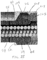
- a contact tip-diffuser 86a defines a plurality of slots 86b and a plurality of holes 86c extending through the outer wall 50 of the cylindrical body 36.
- the plurality of slots 86b is evenly spaced radially in relation to the longitudinal axis 84i and forms a row of slots 86d.
- the plurality of holes 86c is evenly spaced radially about the longitudinal axis and forms a row of holes 86e.
- Each hole 86d and each slot 86c also alternate about the outer wall 50 of the cylindrical body 36.
- This example of the contact tip diffuser further demonstrates the different implementations of the plurality of apertures 54 introduced in all of the previous figures.
- FIG. 13B demonstrates a cross-sectional view of a contact tip diffuser
- FIG. 13C demonstrates a curve representing the relationship between the bore length 88a and the tip inside diameter (I.D.) 88b of the contact tip diffuser 84a
- the bore length 88a represents the length of the contact tip diffuser 84a that contacts the welding wire extending from the distal end portion 46 to the radiused inlet 60.
- the tip inside diameter 88b represents the diameter of the cylindrical exit orifice 40.
- the curve 88c illustrates the ratio between the bore length 88a and the tip inside diameter 88b of the exit orifice 40 for the contact tip diffuser 84a and other contact tip diffuser contemplated by the disclosure.
- the curve 88c demonstrates that for smaller welding wires and tip inside diameters 88b, the bore length ratio 88d may be higher. For example, when the tip inside diameter 88b is 7/64 in., the bore length ratio is between 3 and 4, but when the tip inside diameter 88b is 0.045, the bore length ratio 88d is between 6 and 7. In general, the bore length ratio 88d may be between 2 and 9 for contact tips having tip inside diameters between 1/8 in. and 0.035 in. respectively.
- FIG. 13C illustrates guidelines for implementing the contact tip diffusers disclosed and should not be considered limiting to the scope of the disclosure.
- the curve 88c demonstrates that the bore length ratio 88d increases as the tip inside diameter 88b decreases for contact tip diffusers.
- the implementations of the contact tips shown are only exemplary and should not be considered limiting this disclosure.
- Other examples may include multiple rows comprising a plurality of slots, a plurality of holes or any combination thereof further comprising a plurality of gas outlet passages from the cavity 38.
- the gas outlet passages may be formed symmetrically or a-symmetrically in relation to one another and the individual placement of the each outlet passage about the body.
- the gas outlet passages may be formed in any pattern extending around the circumference of the body and may also comprise rows extending at angles radially about the body with respect to the longitudinal axis 84i.
- a row of holes and a row of slots may overlap or a plurality of slots may comprise individual slots each extending lengthwise at a different angles with respect to the longitudinal axis.
- the gas outlet passages may comprise different shapes including but not limited to ellipses and polygons having a variety of chamfered or filleted sides or edges.
- the inner body 94 of the nozzle 22 is configured to function as a tip holder and secure the integrated tip-diffuser 24 therein.
- the inner body 94 includes a generally cylindrical hollow body 76 and includes a proximal end 100 and a distal end 102.
- the inner body 94 defines an internal distal flange 96 at the distal end portion 102, and an intermediate flange 104 between the proximal end portion 100 and the distal end portion 102.
- the internal distal flange 96 defines a peripheral angled surface 106 for contacting the external shoulder 52 of the contact tip-diffuser 24.
- the intermediate flange 104 defines an inner peripheral contact surface 108.
- the internal distal flange 96 abuts the external shoulder 52 of the contact tip-diffuser 24 to secure and position the integrated tip-diffuser 24.
- the inner peripheral contact surface 108 of the inner body 94 contacts the outer contact surface 82 of the conductor tube 14 and the external shoulder 80 of the conductor tube 14 engages the intermediate flange 104 of the inner body 94.
- the angled surface 106 of the internal distal flange 96 of the inner body 94 contacts the outer shoulder 52 of the contact tip-diffuser 24 and prevents the contact tip-diffuser 24 from moving distally as indicated by arrow X.
- the contact tip-diffuser 24 is prevented from moving proximally as indicated by arrow Y by the internal tapered surface 66 of the conductor tube 14.
- the external contact surface 64 of the contact tip-diffuser 24 is configured to match the internal tapered surface 66 of the conductor tube 14 such that when the proximal end portion 44 of the contact tip-diffuser 24 is secured to the distal end portion 26 of the conductor tube 14, the external contact surface 64 of the contact tip-diffuser 24 is in close contact with the internal tapered surface 66 of the conductor tube 14.
- Sufficient physical contact is provided between the external contact surface 64 of the tip-diffuser 24 and the internal tapered surface 66 of the conductor tube 14 such that electrical current can be reliably transferred from the conductor tube 14 to the contact tip-diffuser 24 and heat can be efficiently transferred from the contact tip-diffuser 24 to the conductor tube 14.
- the contact tip-diffuser 24 can be further cooled due to the increased contact area between the contact tip-diffuser 24 and the conductor tube 14. The increased contact area allows efficient heat transfer from the contact tip-diffuser 24 to the conductor tube 14, as opposed to threaded contact surfaces between the contact tip and the diffuser in a prior art welding gun.
- the outer body 90, the insulator 92 and the inner body 94 are pre-assembled to form an integrated nozzle 22 and the contact tip-diffuser 24 is inserted into the nozzle 22 from the proximal end of the nozzle 22 until the external shoulder 52 of the contact tip-diffuser 24 contacts the angled surface 106 of the internal distal flange 96 of the inner body 94.
- the internal distal flange 96 prevents the contact tip-diffuser 24 from further moving distally.
- the distal end portion 26 of the conductor tube 14 is inserted into the proximal end of the nozzle 22 until the distal end portion 26 of the conductor tube 14 is inserted into the space between the external contact surface 64 of the contact tip-diffuser 24 and the inner peripheral contact surface 108 of the inner body 94.
- No tool is required to connect the conductor tube 14 to the consumable assembly 16 that includes the nozzle 22 and the contact tip-diffuser 24.
- No threaded connection is needed for secured connection.
- the contact tip-diffuser 24, the nozzle 22 and the conductor tube 14 can be assembled by simply pressing these components toward one another. Accordingly, manufacturing costs can be reduced.
- the conductor tube 14 can be secured to the inner body 94 of the nozzle 22 through threaded connection as illustrated in other examples.
- a shielding gas is directed from the internal passageway 30 of the conductor tube 14 and enters the internal cavity 38 of the contact tip-diffuser 24.
- the shielding gas is then directed outside the contact tip-diffuser 24 through the plurality of apertures 54.
- the apertures 54 diffuse the shielding gas and provide cooling to the integrated tip-diffuser 24.
- a welding wire 20 is directed from the conductor tube 14, through the internal cavity 38 of the contact tip-diffuser 24 to the exit orifice 40 of the contact tip-diffuser 24. Electrical current is transferred from the conductor tube 14, through the contact tip-diffuser 24, to the welding wire 20.
- the radiused inlet 60 of the exit orifice 40 reduces scraping and shaving of the welding wire.
- the exit orifice 40 provides contact for the welding wire 20.
- the contact tip-diffuser 24 with the integrated structure can be sufficiently cooled due to increased contact surfaces between the contact tip-diffuser 24 and the conductor tube 14 and due to thermal conduction from the contact tip-diffuser 24 to the shielding gas. Also, the shielding gas provides cooling both inside and outside the contact tip-diffuser 24. With sufficient cooling, the contact tip-diffuser 24 can be formed of a hollow structure using less copper alloy to reduce manufacturing costs and can be used for heavy-duty applications (e.g., high amperage operation).
- the contact tip-diffuser 24 with the hollow and integrated structure is relatively easy to manufacture.
- the contact tip-diffuser 24 can be formed by a forming process, including but not limited to, forging, swaging, cold forming, extruding, metal injection molding (MIM), casting, and machining.
- MIM metal injection molding
- the integrated contact tip-diffuser 24 which functions as both a contact tip for transferring electrical current and a diffuser for diffusing a shielding gas reduces total manufacturing costs by eliminating a separate component for a gas diffuser.
- the consumable assembly 120 includes a contact tip 122 and a nozzle 124.
- the contact tip 120 in the present example has a structure similar to that of the contact tip-diffuser 24 of FIG. 15 , except that the contact tip 120 of FIG. 16 does not have any aperture extending through the outer wall 50 of the contact tip 120 to diffuse gas. Instead, the apertures for diffusing shielding gas are formed in the conductor tube 126.
- the contact tip 120 includes an internal cavity 38 and an exit orifice 40.
- a radiused inlet 60 is formed at a distal end 47 of the internal cavity 38.
- the internal cavity 38 is aligned with an internal passageway 128 of the conductor tube 126 to receive a conduit liner 32 (shown in FIG. 2 ).
- the structure of the contact tip 120 is similar to that the contact tip-diffuser 24 of FIG. 15 and the description thereof should be considered similar hereinafter to avoid redundancy.
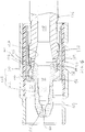
- the conductor tube 126 includes a distal end portion 130 having an internal tapered surface 132 for contacting an external contact surface 134 of the contact tip 122.
- the internal tapered surface 132 and the external contact surface 134 improve electric current transfer and heat transfer between the conductor tube 126 and the contact tip 122.
- the connection among the contact tip 122, the conductor tube 128 and the nozzle 124 is similar to the connection among the contact tip-diffuser 24, the conductor tube 14 and the nozzle 12 of FIG. 15 and thus the detailed description thereof should be considered similar hereinafter to avoid redundancy.
- the distal end portion 130 of the conductor tube 126 defines a plurality of apertures 136 extending through the cylindrical wall 138 of the distal end portion 130. While the plurality of apertures 136 are shown to be oriented in a radial direction of the conductor tube 126, the apertures 136 may be oriented at an angle relative to the longitudinal axis of the conductor tube 126 or has a portion parallel to the longitudinal axis of the conductor tube 126. The plurality of apertures 136 are in fluid communication with the internal passageway 128 of the conductor tube 126. The plurality of apertures 136 are provides proximally from the proximal end portion 44 of the contact tip 122.
- the contact tip 122, a nozzle 124 and the conductor tube 126 are suitable for light-duty application (approximately 250 A and below) by forming the apertures 136 in the conductor tube 126.
- the shielding gas When the shielding gas is directed from a gas source, through the welding cable 18 (shown in FIG. 1 ), and to the distal end portion 130 of the conductor tube 126, the shielding gas can be further directed outside the conductor tube 126 and into a first gas chamber 140 between the nozzle 124 and the distal end portion 130 of the conductor tube 126.
- the first gas chamber 140 is in fluid communication with a second gas chamber 142 between the contact tip 122 and the nozzle 124.
- the shielding gas may be further directed distally to the second gas chamber 142 through vent holes (not shown) formed in the internal distal flange 96 of the nozzle 124 or through gaps (not shown) between the internal distal flange 96 and the contact tip 122.
- a blanket of shielding gas is thus formed around the contact tip 122 to protect the molten metal pool.
- the plurality of apertures 136 may be formed proximate the interface between the conductor tube 126 and the contact tip 122. Therefore, the shielding gas flowing through the apertures 136 may provide sufficient cooling to the contact tip 122 that is subjected to high heat during operation.
- the contact tip 122 is directly secured to the distal end portion 130 of the conductor tube 126 without any intervening component.
- the conductor tube 126 also functions to diffuse shielding gas to form a blanket of shielding gas around the contact tip 122. No separate gas diffuser is needed. Accordingly, the arc welding apparatus 10 that includes the consumable assembly 120 and the conductor tube 126 constructed in accordance with the teachings of the present disclosure has fewer components and thus the manufacturing costs are reduced.
- the apertures can be formed in both the conductor tube 126 and the contact tip 122 such that both conductor tube 126 and the contact tip 122 can diffuse the shielding gas.
- the apertures are formed in both the conductor tube 126 and the contact tip 122, the consumable assembly and the conductor tube are suitable for heavy-duty applications.
- a consumable assembly 202 and a conductor tube 204 for use in the arc welding apparatus 10 and constructed in accordance with a third example of the present disclosure is shown.
- the consumable assembly 202 includes a contact tip 206 and a nozzle 207 surrounding the contact tip 206.
- apertures 130 for directing shielding gas are formed in the conductor tube 204.
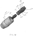
- the contact tip 206 is a stub tip and has a distal end portion 214 defining an elongated exit orifice 216 and a proximal end portion 218 defining an internal cavity 220.
- the elongated exit orifice 216 has a length close to the length of the internal cavity 220, as opposed to the contact tip-diffuser and the contact tip in the first and second examples, where the elongated exit orifice is much shorter than the internal cavity.
- the contact tip 206 of the present example has an external shoulder 240 and a tapered contact surface 219 at the proximal end portion 218.
- the nozzle 207 includes an inner body 208, an outer body 210 surrounding the inner body 208, and an insulator 212 disposed therebetween.
- the inner body 208 of the nozzle 207 includes an enlarged proximal portion 222 and a narrowed distal portion 214.
- the insulator 212 is disposed between the outer body 210 and the enlarged proximal portion 222 of the inner body 208.
- the narrowed distal portion 214 includes an internal distal flange 244 for engaging the external shoulder 240 of the contact tip 206 and a plurality of apertures 226 for diffusing shielding gas. While two apertures 226 are shown in FIGS. 17 and 18 , any number (including one) of apertures 226 can be formed in the inner body 224.
- a gas chamber 228 is defined between the narrowed distal portion 214 of the inner body 208 and the outer body 210 and is in fluid communication with the apertures 226 of the inner body 208.
- the conductor tube 204 includes a distal portion 230 and an engaging portion 232 disposed proximally of the distal portion 230.
- the distal portion 230 defines a plurality of apertures 234 in fluid communication with the apertures 226 of the inner body 208.
- the distal portion 230 further defines an internal tapered surface 235 for contacting the external tapered surface 219 of the contact tip 206.
- the engaging portion 232 may includes a plurality of cam lock connection parts 236 for securing the conductor tube 204 in the nozzle 202.
- three cam lock connection parts 236 may be provided along the circumference of the engaging portion 232 at 120° apart.
- the cam lock connection parts 236 each having opposing ends 250, 252 along the circumference of the conductor tube 204.
- One end 250 has a first thickness greater than a second thickness of the other end 252 such that a tapered surface 254 is formed between the opposing ends 250, 252.
- the cam lock connection parts 236 allow the conductor tube 204 to be secured inside the nozzle 207 in a sliding manner.
- engaging portion 232 may be provided with threads for threaded connection with the inner body 208 of the nozzle 208 threaded connection as illustrated in other examples.
- the cam lock connection parts 236 engage an inner surface 238 of the enlarged proximal portion 222 of the inner body 208. Moreover, the distal portion 230 of the conductor tube 204 engages the inner surface 240 of the narrowed distal portion 224. When the conductor tube 204 is positioned in place, the apertures 230 of the conductor tube are aligned radially with the apertures 226 of the inner body 208 and the outer tapered surface 219 is in close contact with the internal tapered contact surface 235 of the conductor tube 204.
- the internal and external tapered contact surfaces 219 and 235 improve heat transfer from the contact tip 206 to the conductor tube 204, thereby providing more efficient cooling to the contact tip 206.
- the consumable assembly 202 and the conductor tube 204 are suitable for light-duty applications.
- FIGS. 19A and 19B the conductor tube 204 demonstrated in FIGS. 17 and 18 is shown in different variations still in accordance with the third example of the present disclosure.
- FIG. 19A demonstrates an example of a conductor tube 260 variation.
- the plurality of apertures 234 is formed as a plurality of slots 262.
- FIG. 19B demonstrates a conductor tube 264 having a plurality of slots 266 and a plurality of holes 268.
- the conductor tubes 260 and 264 shown in FIGS. 19A and 19B may have other variations similar to those demonstrated in FIGS. 9 to 13 similar to the contact tip diffusers to alter the dispersion and improve the coverage of shielding gas.
- FIGS. 20A and 20B refer back to the consumable assembly 202 and the conductor tube 204 constructed in accordance with the third example of the present disclosure, and further disclose an alignment device 270.
- the alignment device serves as a guide to center a conduit liner (not shown) similar to the conduit liner 32 introduced in FIGS. 2 to 4 within the internal passageway 128 inside the conductor tube 204 and along a longitudinal axis 272.
- the alignment device 270 positions the conduit liner and accordingly the wire such that the portion extending into the internal cavity 220 of the contact tip 206 is aligned with the elongated exit orifice 216 along the longitudinal axis 272.
- the addition of the alignment device 270 to the third example results in the conduit liner extending into the internal cavity 220 from an internal passage 274.
- the internal passage defines an internal tapered surface 276 disposed centrally in the alignment device 270.
- the alignment device 270 provides for the welding wire fed through the conduit liner to consistently enter a radiused inlet 60 and feed outward through the exit orifice 216.
- the alignment device improves operation of the arc welding apparatus 10 by reducing inconsistencies in feeding the welding wire through the contact tip 206.
- the alignment device 270 further comprises a press fit surface 278 being pressed into the distal end portion 130 of the conductor tube 204 in a press fit cavity 280.
- the press fit surface 274 is shown having a chamfer 282 disposed around a proximal end 284 for ease of manufacture when being pressed into the distal end portion 130 of the conductor tube 204 and abutting the press fit cavity 276.
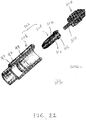
- FIGS. 21A and 21B the inner body 204 demonstrated in FIGS. 17 and 18 is shown in a different variation similar to the third example of the present disclosure.
- An adaptor sleeve 286 having an internal cavity 288 defining cam lock parts 290 attaches to the conductor tube 204 of the third example.
- the adaptor sleeve 206 further comprises a plurality of apertures 292 extending from an outer surface 294 to the internal cavity 288 and a plurality of threads 296 disposed around the outer surface for attachment to a nozzle (not shown) assembly similar to the nozzle 207 disclosed in the third example.
- the inner body 208 of the nozzle 207 attaches to the plurality of threads 296 and comprises an internal distal flange (not shown) to secure the contact tip 206 in conformity with the teachings of the disclosure.
- the consumable assembly 302 includes a nozzle 306 and a contact tip-diffuser 308.
- a conduit liner 310 extends longitudinally through the conductor tube 304.
- the contact tip-diffuser 308 includes apertures 312 for diffusing shielding gas from inside the contact tip-diffuser 308 to outside of the contact tip-diffuser 308 and thus functions as both a contact tip and a gas diffuser in the present embodiment.
- the contact tip-diffuser 308 is structurally similar to the contact tip-diffuser 24 of FIG. 5 except that the proximal end portion 314 of the contact tip-diffuser 308 includes a spherical contact surface 316.
- Like reference numbers will be used for like parts as such these parts may function in a similar manner as previously described in this application.
- the contact tip-diffuser 308 includes a proximal end portion 314 defining an internal cavity 38 and a distal end portion 46 defining an elongated exit orifice 40.
- the proximal end portion 314 includes an external shoulder 52 and a spherical contact surface 316.
- the contact tip-diffuser 308 has a plurality of apertures 54 extending radially through the proximal end portion 314 to diffuse shielding gas. Therefore, the consumable assembly 302 is suitable for heavy-duty (e.g., high amperage) welding operation.
- the nozzle 306 has a structure similar to that the nozzle in FIG. 15 .
- Like reference numbers are used for like parts and thus the description and the description thereof should be considered similar hereinafter to avoid redundancy.
- the conductor tube 304 of the present example is structurally similar to the conductor tube of FIG. 15 , except that the conductor tube 304 defines a spherical contact surface 324 corresponding to the spherical contact surface 316 of the contact tip-diffuser 308.
- the spherical contacts surfaces 316 and 324 of the contact tip-diffuser 308 and the conductor tube 304 improve engagement between the tip/diffuser 308 and the conductor tube 304.
- the consumable assembly 402 includes a contact tip-diffuser 404 and a nozzle 406.
- the contact tip-diffuser 404 is similar to the contact tip-diffuser 308 of FIGS. 15 to 16 except that the contact tip-diffuser 308 has an annular groove 408 formed in the spherical contact surface 316.
- Like reference numbers are used for like parts as such these parts may function in a similar manner as previously described in this application.
- the contact tip-diffuser 308 of the present disclosure has a proximal end portion 314 and a distal end portion 46.
- the proximal end portion 314 has an external shoulder 52 and a spherical contact surface 316.
- An annular groove 418 is formed along the circumference of the spherical contact surface 316.
- the spherical contact surface 316 of the contact tip-diffuser 404 is in close contact with the spherical contact surface 324 of the conductor tube 404.
- the annular groove 408 prevents possible locking of the contact tip-diffuser 404 to the conductor tube 404 due to thermal expansion of the spherical contact surfaces 316 and 324.
- the consumable assembly 402 includes a contact tip 406 and a nozzle assembly 408.
- the contact tip 406 is similar to the contact tip 122 in FIG. 16 and includes an external contact surface 407 that is tapered outwardly from the proximal end portion to the distal end portion.
- the nozzle assembly 408 includes a nozzle housing 410 and a nozzle cup 412 mounted around a distal end 413 of the nozzle housing 410.
- the nozzle cup 412 may be assembled to the nozzle housing 410 through threaded connection, or quick disconnects, among other types of connections.
- the nozzle housing 410 includes an outer body 414, an inner body 416 and an insulator 418 disposed between the outer body 414 and the inner body 416.
- the inner body 414 functions as a tip holder for securing the contact tip 122.
- the conductor tube 404 includes a distal end portion 420 having an internal contact surface 422 and an external connecting surface 423.
- the distal end portion 420 may be formed separately and molded to the main body of the conductor tube 404. Alternatively, the distal end portion 420 may be an integral part of the conductor tube 404.
- the internal contact surface 422 is tapered to match the external contact surface 407 of the contact tip 406.
- the external connecting surface 423 may have threads for threaded connection with the inner body 416 of the nozzle assembly 408.
- a plurality of apertures 424 extend through the internal contact surface 422.
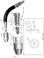
- FIGS. 28 to 30 refer to a consumable assembly 450 and a conductor tube 452 for use in the arc welding apparatus 10 of FIG. 1 and constructed in accordance with a seventh example of the present disclosure.
- a consumable assembly 450 is similar to the consumable assembly 16 of the first example and as such these parts may function in a similar manner as previously described in this application.
- a nozzle assembly 452 attaches to a conductor tube 454 through an intermediate connection in the form of a sleeve 456 and an engaging portion 458 comprising a plurality of threads 460.
- the instant implementations additionally incorporates an alignment device 462 disposed in the conductor tube 454 to align a conduit liner with a contact diffuser tip 464.
- This example provides for an alternative means of connecting the disposable assembly 450 to the conductor tube 454 with an added benefit of a replaceable sleeve 456 to allow for replacement of the plurality of threads 460 without replacing the conductor tube 454.
- the sleeve 456 engages the distal end 466 of the conductor tube 454.
- An inner surface profile 468 of the sleeve 456 is configured to slide over an external surface profile 470 of the conductor tube 454.
- the sleeve 456 is further held in position by a locking ring 472 disposed in an annular groove 474.
- the engaging portion 458 of the sleeve 456 comprises the plurality of threads 460 that connects to an inner body portion 476 of the nozzle assembly 452 also comprising a plurality of threads 478.
- the alignment device 462 serves to center a conduit liner (not shown) similar to the conduit liner 310 introduced in FIG. 20 within an internal passageway 480 inside the conductor tube 454 along a longitudinal axis 482.
- the alignment device 462 positions the conduit liner such that the portion extending into the internal cavity 484 of the contact tip diffuser 464 is aligned with the exit orifice 486 along the longitudinal axis 482.
- the addition of alignment device 462 to this example results in the conduit liner extending into the internal cavity 484 providing for the welding wire fed through the conduit liner to consistently enter a radiused inlet 488 and be fed out through the exit orifice 486.
- Another feature of the alignment device 462 disclosed in the seventh embodiment is a plurality of ports 490 bordering on an internal passage 492.
- the conduit liner is disposed in the internal passage 492 to align the conduit liner with the internal cavity 484 of the contact tip diffuser 464 and the plurality of ports 490 provides increased cross-sectional area within the conductor tube 454.
- the increased cross-sectional area ensures that the alignment device 462 does not restrict the flow of shielding gas through the conductor tube 454.
- the alignment device 462 comprises a press fit surface 502 is pressed into the distal end 466 of the conductor tube 454 into a press fit cavity 504.
- the distal end 466 of the conductor tube 454 further defines an external surface profile 506 that is significantly circular having a radial alignment mechanism such as a flat, tab, keyed-slot, or groove.
- a flat 508 is disposed on two opposing sides for radial alignment.
- the inner profile 468 of the sleeve 456 is configured to slidably engage the external surface profile 508 such that the sleeve 456 can slide along the longitudinal axis 482, but is restricted from rotating around the conductor tube 454.
- the locking ring 472 is disposed in the annular groove 474. With the locking ring 472 in place, the sleeve 456 is sufficiently restrained.
- the contact tip diffuser 464 engages the distal end 466 of the conductor tube 454 and the inner body 476 of the nozzle assembly 452 connects to the engaging portion 458 of the sleeve 456 through the mating surfaces of each of the plurality of threads 460 and 478.
- the assembly of the instant example of the welding apparatus is further detailed in an assembled, cross-sectional view shown in FIG. 30 with only the inner body 476 of the nozzle assembly 452 shown for clarity.
- the inner body 476 further defines an internal distal flange 520 that abuts an external shoulder 522 of the contact tip diffuser 464 and retains the position of the contact tip diffuser 464.
- the engaging portion 458 of the sleeve 456 defined as the plurality of threads 460 is clearly shown engaging the plurality of threads 478 of the inner body 476.
- the press fit cavity 504 of the conductor tube is shown to demonstrate the press fit surface 502 of the alignment device 462 assembled according to the instant example.
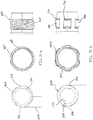
- FIG. 31A illustrates the connection of the sleeve 456 and the conductor tube 454.
- the external surface profile 506 at the distal end 466 of the conductor tube 454 comprises a flat 508 on two opposing sides.
- the inner surface profile 468 of the sleeve 456 is configured to slidably engage the external surface profile 506 such that the sleeve 456 can slide along the longitudinal axis 482, but is restricted from rotating around the conductor tube 454.
- the engaging portion 458 and the plurality of threads 460 are also shown in FIG 31A to provide further detail.
- FIG. 31B a different variation of a sleeve 550 and a conductor tube 552 are shown in FIG. 31B .
- an external surface profile 554 of the conductor tube is defined as having a key slot 556 and a key 558 to engage an inner surface profile 560 of the sleeve 550.
- the sleeve 550 engages the distal end 562 of the conductor tube 552 and is restricted from rotation about the conductor tube 552 with the key 558 disposed in the key slot 556 and in the inner surface profile 560 of the sleeve 550.
- the conductor tube 552 may similarly be configured to engage an inner surface profile of a sleeve through a spline coupling. Further the engaging portion 564 of the sleeve 550 is defined as cam lock parts 566. Similar to the first example, the cam lock parts 566 engage an inner body of a nozzle assembly (not shown) rather than the plurality of threads 460 in the consumable assembly of the seventh example.
- FIG. 32 a different variation of a conductor tube 568 and a sleeve 570 are shown in FIG. 32 .
- This variation is similar to that disclosed in FIG. 31A , but includes a set screw 572 as a means of securing the sleeve 570 to the conductor tube 568.
- the set screw 572 is disposed in a hole 574 in the sleeve 570 and a threaded hole 576 in the conductor tube 568 to secure the sleeve 570 to the conductor tube 568.
- This implementation may further include the sleeve 570 having an elongated surface 578 that extends at least to the distal end 466 of the conductor tube 568 when assembled.
- the instant implementation applies the sleeve 570 to protect the distal end 466 of the conductor tube 568 from wear and protect the distal end 466 from impact.
- FIG. 33A illustrates the alignment device 462.
- the plurality of ports 490 is clearly depicted as being evenly spaced around and bordering the internal passage 492. The even spacing of the plurality of ports allows for consistent passage of shielding gas through alignment device 462.
- the press fit surface 502 is shown having a chamfer 602 disposed in a proximal end 604 for ease of manufacture when being pressed into the distal end 466 of the conductor tube 454 and abutting the press fit cavity 504.
- FIGS. 33B and 33C different variations of the alignment device 462 similar to seventh example are shown providing alternate examples that can be incorporated from the aforementioned teachings of this disclosure.
- the alignment device 606 shown in FIG 33B has a plurality of ports 608 disposed within the wall 610 of the alignment device 606.
- the instant example has as an outer surface 612 defining a plurality of threads 614 configured to connect to a threaded surface disposed in a conductor tube.
- the alignment device 616 shown in FIG 33B has a plurality of ports 618 such that when the alignment device 616 is disposed in a conductor tube (not shown), the plurality of ports 618 border an interior surface 619 (shown as a dotted line) of the conductor tube. Further, an outer surface 620 is disposed around the alignment device 616 and comprises cam lock parts 622. In this example, the interior surface of the conductor tube further defines an engaging portion configured to engage the cam lock parts 622 and retain the alignment device 616.
- the previous examples are not suggested to limit other variations and are presented to teach possible examples of this disclosure.
Landscapes
- Engineering & Computer Science (AREA)
- Physics & Mathematics (AREA)
- Plasma & Fusion (AREA)
- Mechanical Engineering (AREA)
- Arc Welding In General (AREA)
- Butt Welding And Welding Of Specific Article (AREA)
Description
- The present disclosure relates generally to welding apparatuses, and more particularly to an arc welding apparatus (see claim 1) such as Metal Insert Gas (MIG) or Gas Metal Arc Welding (GMAW) welding guns including consumables for generating welding arc and diffusing shield gas.
- The present disclosure relates also to a method of operating such arc welding apparatus (see claim 12).
- The statements in this section merely provide background information related to the present disclosure and may not constitute prior art.
- In an arc welding apparatus, such as Metal Insert Gas (MIG) or Gas Metal Arc Welding (GMAW) welding gun, a welding wire is fed through the welding gun to provide a molten metal pool to join metal workpieces together. An inert gas is directed through the front (distal) end of the welding gun to provide a surrounding layer or blanket of shielding gas to protect the molten metal pool from atmospheric contamination. The inert gas is typically a combination of various gases such as argon or helium, among others.
- A prior art MIG or GMAW welding gun typically includes a contact tip and a gas diffuser connected to the contact tip. The contact tip has a central bore to guide the welding wire to the workpieces. The contact tip transfers electrical current to the welding wire. The gas diffuser is threaded to the contact tip and defines gas passageways to direct the shielding gas into forming the blanket of shielding gas around the molten metal pool. The contact tip and gas diffuser are constantly subjected to high heat and are susceptible to wear due to high temperature operation.
-
US3 249 73 , which is considered to represent the most relevant state of the art, describes an arc welding apparatus with a conductor tube, having at least one aperture closed to the distal end of the conductor tube, a contact tip threaded to the distal end of the conductor tube, and a nozzle. - The present invention defines an arc welding apparatus according to
claim 1, and includes a contact tip defining a body having an internal cavity extending from a proximal end portion to a distal end portion and an exit orifice extending through the distal end portion of the body. The body further defines a contact surface disposed around the proximal end portion wherein the contact surface defines a profile configured to abut a corresponding profile on a conductor tube. The arc welding apparatus further includes a conductor tube defining an internal passageway, at least one aperture, and a contact surface disposed around a distal end. The contact surface defines a profile configured to abut a corresponding profile on the contact tip. The aperture extends outward from the internal passageway proximate to a distal end portion of the conductor tube and allows shielding gas to flow out of the internal passageway. - According also to the present invention, a method of operating such arc welding apparatus is defined in
claim 12.
The method provides for operation by directing a flow of shielding gas through at least one aperture in a distal end portion of a conductor tube. The method further discloses directing a welding wire through an exit orifice in a contact tip wherein the at least on aperture diffuses a shielding gas and provides cooling to the tip, and the exit orifice provides contact for the welding wire. - Further areas of applicability will become apparent from the description provided herein. It should be understood that the description and specific examples are intended for purposes of illustration only and are not intended to limit the scope of the present disclosure.
- The drawings described herein are for illustration purposes only and are not intended to limit the scope of the present disclosure in any way.
-
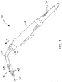
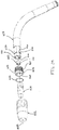
FIG. 1 is a side view of an arc welding apparatus including a contact tip-diffuser; -
FIG. 2 is a cross-sectional perspective view of a consumable assembly connected to a conductor tube and having a contact tip-diffuser; -
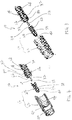
FIG. 3 is a partial exploded, perspective view of a conductor tube and a consumable assembly; -
FIG. 4 is a partial exploded, cross-sectional view of a conductor tube and a consumable assembly; -
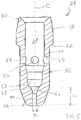
FIG. 5 is a cross-sectional view of a contact tip-diffuser; -
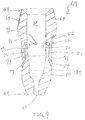
FIG. 6 is a cross-sectional view of a variant form of a contact tip-diffuser; -
FIG. 7 is a cross-sectional view of another form of a contact tip-diffuser; -
FIG. 8 is a cross-sectional view of another form of a contact tip-diffuser; -
FIG. 9 is a cross-sectional view of another form of a contact tip-diffuser; -
FIG. 10 is a cross-sectional view of another form of a contact tip-diffuser; -
FIG. 11 is a cross-sectional view of another form of a contact tip-diffuser; -
FIG. 12 is a cross-sectional view of another form of a contact tip-diffuser; -
FIG. 13A is a cross-sectional view of another form of a contact tip-diffuserFIG. 13B is a cross-sectional view of a contact tip diffuser, and 13C is a curve representing the relationship between the tip bore length and the tip inside diameter; -
FIG. 14 is a cross-sectional, perspective view of an inner body of a nozzle; -
FIG. 15 is a cross-sectional view of a consumable assembly and a conductor tube of the arc welding apparatus ; -
FIG. 16 is a cross-sectional view of a consumable assembly and a conductor tube of an arc welding apparatus; -
FIG. 17 is a partial exploded view of a consumable assembly and a conductor tube of an arc welding apparatus, and -
FIG. 18 is a cross-sectional view of a consumable assembly and a conductor tube of an arc welding apparatus; -
FIG. 19 is a profile and cross-sectional view of the conductor tube of an arc welding apparatus; -
FIG. 20 is a partially exploded profile and cross-sectional view of an arc welding apparatus, and a detail view of an alignment device; -
FIG. 21 is a partially exploded profile and cross-sectional view of the conductor tube and adaptor sleeve of an arc welding apparatus; -
FIG. 22 is a perspective view of a contact tip-diffuser of a consumable assembly; -
FIG. 23 is a cross-sectional view of a consumable assembly and a conductor tube; -
FIG. 24 is a cross-sectional view of a consumable assembly and a conductor tube; -
FIG. 25 is an enlarged view ofFIG. 24 , showing the interface between the contact tip-diffuser and the conductor tube; -
FIG. 26 is a perspective view of a consumable assembly and a conductor tube; -
FIG. 27 is a partial exploded, cross-sectional and perspective view of a consumable assembly and a conductor tube; -
FIG. 28 is a partial exploded perspective view and partial exploded cross-sectional view of a consumable assembly and a conductor tube; -
FIG. 29 is a partial exploded perspective view of a consumable assembly and a conductor tube; -
FIG. 30 is a cross-sectional view of a consumable assembly and a conductor tube -
FIG. 31A is a detail view of a conductor tube and a sleeve , - and
FIG. 31B is a detail view conductor tube and sleeve demonstrating an alternate conductor tube and sleeve related thereto; -
FIG. 32 is perspective view and a partial exploded perspective view of a consumable assembly and a conductor tube, and -
FIG. 33A is a detail view of an alignment device andFIG. 33B and 33C are detail views of alignment devices demonstrating alternate conductor configurations related thereto. - The following description is merely exemplary in nature and is in no way intended to limit the present disclosure or its application or uses. It should be understood that throughout the description and drawings, corresponding reference numerals indicate like or corresponding parts and features. And although the term "MIG" or "GMAW" is used throughout the specification, it should be understood that the teachings of the present disclosure apply to any type of welding gun.
- Referring to
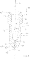
FIG. 1 , an arc welding apparatus, such as a MIG or GMAW welding gun, is illustrated and generally indicated byreference numeral 10. TheMIG welding gun 10 includes ahandle 12, aconductor tube 14 attached to thehandle 12, and aconsumable assembly 16 attached to theconductor tube 14. Thehandle 12 is connected to awelding cable 18 that carries welding current, shielding gas, and awelding wire 20 from a power source (not shown), a gas source (not shown), and a wire feeder (not shown) to thewelding gun 10. - The
consumable assembly 16 includes a plurality of consumable components and generally includes anozzle 22 and a contact tip-diffuser 24 disposed inside thenozzle 22 according to a first example of the present disclosure. The structure and operation of the arc welding apparatus has been disclosed inU.S. Patent Nos. 5,491,321 and5,338,917 , which are commonly owned by the assignee of the present application, and the contents of which are incorporated herein by reference in their entirety. - Referring to
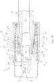
FIGS. 2 through 4 , theconsumable assembly 16 is connected to adistal end portion 26 of theconductor tube 14. Thenozzle 22 is substantially cylindrical and receives thedistal end portion 26 of theconductor tube 14 therein. The contact tip-diffuser 24 is coaxially disposed inside thenozzle 22 and has a portion inserted into thedistal end portion 26 of theconductor tube 14. Theconductor tube 14 includes acylindrical conductor body 28 defining aninternal passageway 30, and aconduit liner 32 disposed in theinternal passageway 30. Theconduit liner 32 has a guidingchannel 34 for guiding thewelding wire 20 from thewelding cable 18 and thehandle 12 to the contact tip-diffuser 24. - The
nozzle 22 includes anouter body 90, aninsulator 92 and aninner body 94, which are integrally formed as a single integrated unit. Theinsulator 92 is disposed between theouter body 90 and theinner body 94 for insulating theinner body 94 from theouter body 90. Thenozzle 22 is disposed around the integrated tip-diffuser 24 and secured to thedistal end portion 26 of theconductor tube 14. Thedistal end portion 26 of theconductor tube 14 defines an internal taperedsurface 66, anexternal shoulder 80, and anouter contact surface 82 proximate the external shoulder. - The contact tip-
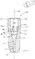
diffuser 24 has an integrated structure and functions as both a contact tip for transferring electrical current and a gas diffuser for diffusing shielding gas. The contact tip-diffuser 24 includes a hollowcylindrical body 36 defining aninternal cavity 38 and anexit orifice 40 open to and aligned with theinternal cavity 38. Theinternal cavity 38 and theexit orifice 40 jointly extend the entire length of the contact tip-diffuser 24. Theinternal cavity 38 of the contact tip-diffuser 24 is aligned with theinternal passageway 30 of theconductor tube 14 such that theconduit liner 32 of theconductor tube 14 can extend into theinternal cavity 38 of the contact tip-diffuser 24. In one example, thecylindrical body 36 of the contact tip-diffuser 24 is made of a copper alloy, such as C18200, C181500 or C12200DHP and can be produced by machining or other large volume manufacturing processes such as cold forming, extruding or the combination of the two. - As clearly shown in
FIG. 5 , the contact tip-diffuser 24 includes thecylindrical body 36 defining aproximal end portion 44 proximate theconductor tube 14 and adistal end portion 46 proximate the workpieces. Theinternal cavity 38 extends from theproximal end portion 44 to thedistal end portion 46 and is substantially cylindrical. Thecylindrical body 36 further includes anouter wall 50, anouter shoulder 52 disposed at theproximal end portion 44, and aninner shoulder 53 disposed near thedistal end portion 46 of thecylindrical body 36. Theinner shoulder 53 is also disposed at adistal end 47 of theinternal cavity 38 and provides a stop for theconduit liner 32 of theconductor tube 14. - A plurality of
apertures 54 extend through theouter wall 50 of thecylindrical body 36 into theinternal cavity 38 and are located between theproximal end portion 44 and thedistal end portion 46. In the present embodiment, four apertures 54 (only three are shown) extend normally (e.g. perpendicularly) through theouter wall 50 of thecylindrical body 36 and are spaced at 90°. It is understood that any number of apertures can be formed through theouter wall 50 of the contact tip-diffuser 24 without departing from the scope of the present disclosure. During operation, the shielding gas is directed from theinternal passageway 30 of theconductor tube 14 into theinternal cavity 38 of the contact tip-diffuser 24. The shielding gas is then directed outside the contact tip-diffuser 24 through the plurality ofapertures 54 to form a blanket of shielding gas surrounding the contact tip-diffuser 24 and between the contact tip-diffuser 24 and thenozzle 22. The blanket of shielding gas protects the molten metal pool during operation. - By directing the shielding gas from inside the contact tip-
diffuser 24 to outside the contact tip-diffuser 24 and making the shielding gas in direct contact with the contact tip-diffuser, the contact tip-diffuser 24 can be more efficiently cooled by the shielding gas. Heat transfer from the contact tip-diffuser 24 to the shielding gas can be achieved via thermal conduction and convection, as opposed to thermal radiation or convection in the prior art arc welding apparatuses where the shielding gas does not flow through the contact tip. Moreover, according to the present disclosure, the shielding gas provides cooling both inside and outside the contact tip-diffuser 24 and thus can more quickly remove heat from the contact tip-diffuser 24. - The
exit orifice 40 extends through thedistal end portion 46 of thecylindrical body 36 and has a length L1, which is approximately four times the size (e.g., the diameter D1) of the opening of theexit orifice 40. In the present example, theexit orifice 40 is centered along a centerline C of thecylindrical body 36. Theexit orifice 40 defines aradiused inlet 60. Theradiused inlet 60 reduces scraping and shaving of thewelding wire 20 when thewelding wire 20 moves through theexit orifice 40. The length L1 of theexit orifice 40 is made smaller than that of the exit orifice in a prior art contact tip to provide controlled contact between thewelding wire 20 and the contact tip-diffuser 24 for improved arc stability and less chance of exit orifice obstruction. Moreover, the smaller length of theexit orifice 40 reduces friction surface between thewelding wire 20 and the contact tip-diffuser 24. - An
external contact surface 64 is disposed around theproximal end portion 44 of thecylindrical body 36 and defines a taper configured to abut a corresponding internal tapered surface 66 (shown inFIGs. 2 and4 ) of theconductor tube 14, which will be described in more detail below. Theexternal contact surface 64 is tapered outwardly from theproximal end portion 44 towards thedistal end portion 46. -
FIGS. 6 to 13 refer to various examples of the contact tip diffuser similar to that ofFIG. 3 . Referring toFIGS. 6 and7 , another form of a contact tip-diffuser 68 is similar to that ofFIG. 3 except for the orientation of the apertures. In the example ofFIG. 6 , a contact tip-diffuser 68 defines a plurality ofapertures 70 extending at an angle through theouter wall 50 of thecylindrical body 36. In the example ofFIG. 7 , a contact tip-diffuser 69 has a plurality of apertures 71 each having aninlet 73, an axial passage 75, and anoutlet 77. The axial passage 75 extends along a longitudinal direction of the contact tip-diffuser 69 and connects theinlet 73 open to theinternal cavity 38 to theoutlet 77 formed on anexterior portion 79 of theouter wall 50. - Referring to
FIG. 8 , another form of a contact tip-diffuser 72 is similar to that ofFIG. 3 , except for the configuration of the exit orifice. The contact tip-diffuser 72 defines an exit orifice 74 that is offset from the centerline C of thecylindrical body 36. The exit orifice 74 generally defines a wave shape to create a plurality of contact points 76. The wave shape may be significantly sinusoidal or have increasing or decreasing wavelengths along the length of passage extending toward the exit orifice. When thewelding wire 20 moves through the exit orifice 74, thewelding wire 20 contacts the plurality of contact points 76, which improve contact between thewelding wire 20 and the contact tip-diffuser 24, thereby providing stable current transfer from the contact tip-diffuser 24 to thewelding wire 20. - Referring to
FIGS. 9 through 12 , other variations of contact tip-diffusers 84a to 84d are similar to that ofFIG. 3 except for the plurality ofapertures 54 are defined various forms and orientations of a plurality ofslots 84e to 84h. As used herein, the term slot shall be construed to mean an aperture or opening defining a geometry having a length greater than or equal to a width in a substantially rectangular form. - In the example of
FIG. 9 , a contact tip-diffuser 84a defines a plurality ofslots 84e, having a length and width, the length being longer than the width across a symmetric axis of theslot 84e. The plurality of slots further define the length of the eachslot 84e extending at an angle perpendicular to thelongitudinal axis 84i of thecylindrical body 36. The plurality ofslots 84e may be defined as a plurality ofpolygonal openings 84j significantly square in shape that promote more consistent shielding gas flow and coverage. In the example ofFIG. 10 , a contact tip diffuser 84b has a plurality ofslots 84f, the length of each slot extending parallel to thelongitudinal axis 84i. Each slot may have a significantly rounded profile 84k about two ends. Further, in this example the slots are formed at an angle in relation to theouter wall 50 of thecylindrical body 36 causing the shielding gas to be directed rotationally in thenozzle 22. The angle in relation to theouter wall 50 is shown having an acute side extending axially; however the acute side may extend longitudinally or at an intermediate position between the radial and longitudinal axis. - Referring now to
FIG. 11 , a contact tip diffuser 84c is shown having plurality ofslots 84g each having a length extending parallel to thelongitudinal axis 84i and each slot is shown having a rounded internal passage wall 84I. The internal passage wall 84I of each slot may also comprise chamfers, fillets or other variations and combinations thereof to optimize the flow of the shielding gas. InFIG. 12 another example of acontact tip diffuser 84d has plurality ofslots 84h each extending at an angle in relation to thelongitudinal axis 84i. - In the example of
FIG. 13A , a contact tip-diffuser 86a defines a plurality ofslots 86b and a plurality ofholes 86c extending through theouter wall 50 of thecylindrical body 36. In this example, the plurality ofslots 86b is evenly spaced radially in relation to thelongitudinal axis 84i and forms a row ofslots 86d. Further the plurality ofholes 86c is evenly spaced radially about the longitudinal axis and forms a row of holes 86e. Eachhole 86d and eachslot 86c also alternate about theouter wall 50 of thecylindrical body 36. This example of the contact tip diffuser further demonstrates the different implementations of the plurality ofapertures 54 introduced in all of the previous figures. - Referring to
FIGS. 13B and 13C, FIG. 13B demonstrates a cross-sectional view of a contact tip diffuser, andFIG. 13C demonstrates a curve representing the relationship between thebore length 88a and the tip inside diameter (I.D.) 88b of thecontact tip diffuser 84a. Thebore length 88a represents the length of thecontact tip diffuser 84a that contacts the welding wire extending from thedistal end portion 46 to theradiused inlet 60. The tip insidediameter 88b represents the diameter of thecylindrical exit orifice 40. The curve 88c illustrates the ratio between thebore length 88a and the tip insidediameter 88b of theexit orifice 40 for thecontact tip diffuser 84a and other contact tip diffuser contemplated by the disclosure. - The curve 88c demonstrates that for smaller welding wires and tip inside
diameters 88b, thebore length ratio 88d may be higher. For example, when the tip insidediameter 88b is 7/64 in., the bore length ratio is between 3 and 4, but when the tip insidediameter 88b is 0.045, thebore length ratio 88d is between 6 and 7. In general, thebore length ratio 88d may be between 2 and 9 for contact tips having tip inside diameters between 1/8 in. and 0.035 in. respectively.FIG. 13C illustrates guidelines for implementing the contact tip diffusers disclosed and should not be considered limiting to the scope of the disclosure. The curve 88c demonstrates that thebore length ratio 88d increases as the tip insidediameter 88b decreases for contact tip diffusers. - The implementations of the contact tips shown are only exemplary and should not be considered limiting this disclosure. Other examples may include multiple rows comprising a plurality of slots, a plurality of holes or any combination thereof further comprising a plurality of gas outlet passages from the
cavity 38. The gas outlet passages may be formed symmetrically or a-symmetrically in relation to one another and the individual placement of the each outlet passage about the body. The gas outlet passages may be formed in any pattern extending around the circumference of the body and may also comprise rows extending at angles radially about the body with respect to thelongitudinal axis 84i. - In yet another implementation a row of holes and a row of slots may overlap or a plurality of slots may comprise individual slots each extending lengthwise at a different angles with respect to the longitudinal axis. Finally the gas outlet passages may comprise different shapes including but not limited to ellipses and polygons having a variety of chamfered or filleted sides or edges. Each of the previous examples demonstrates an implementation of gas outlet passages that direct shielding gas into the
nozzle 22 and provide for improved cooling of thecontact tip diffuser 24 while maintaining shielding gas coverage for improved contact tip life for implementations in accordance with this disclosure. - Referring to
FIG. 14 , theinner body 94 of thenozzle 22 is configured to function as a tip holder and secure the integrated tip-diffuser 24 therein. Theinner body 94 includes a generally cylindricalhollow body 76 and includes aproximal end 100 and adistal end 102. Theinner body 94 defines an internaldistal flange 96 at thedistal end portion 102, and anintermediate flange 104 between theproximal end portion 100 and thedistal end portion 102. The internaldistal flange 96 defines a peripheralangled surface 106 for contacting theexternal shoulder 52 of the contact tip-diffuser 24. Theintermediate flange 104 defines an innerperipheral contact surface 108. The internaldistal flange 96 abuts theexternal shoulder 52 of the contact tip-diffuser 24 to secure and position the integrated tip-diffuser 24. - Referring to
FIG. 15 , when theconductor tube 14 and the contact tip-diffuser 24 are inserted into thenozzle 22, the innerperipheral contact surface 108 of theinner body 94 contacts theouter contact surface 82 of theconductor tube 14 and theexternal shoulder 80 of theconductor tube 14 engages theintermediate flange 104 of theinner body 94. Theangled surface 106 of the internaldistal flange 96 of theinner body 94 contacts theouter shoulder 52 of the contact tip-diffuser 24 and prevents the contact tip-diffuser 24 from moving distally as indicated by arrow X. The contact tip-diffuser 24 is prevented from moving proximally as indicated by arrow Y by the internal taperedsurface 66 of theconductor tube 14. Theexternal contact surface 64 of the contact tip-diffuser 24 is configured to match the internal taperedsurface 66 of theconductor tube 14 such that when theproximal end portion 44 of the contact tip-diffuser 24 is secured to thedistal end portion 26 of theconductor tube 14, theexternal contact surface 64 of the contact tip-diffuser 24 is in close contact with the internal taperedsurface 66 of theconductor tube 14. - Sufficient physical contact is provided between the
external contact surface 64 of the tip-diffuser 24 and the internal taperedsurface 66 of theconductor tube 14 such that electrical current can be reliably transferred from theconductor tube 14 to the contact tip-diffuser 24 and heat can be efficiently transferred from the contact tip-diffuser 24 to theconductor tube 14. In addition to being cooled by the shielding gas, the contact tip-diffuser 24 can be further cooled due to the increased contact area between the contact tip-diffuser 24 and theconductor tube 14. The increased contact area allows efficient heat transfer from the contact tip-diffuser 24 to theconductor tube 14, as opposed to threaded contact surfaces between the contact tip and the diffuser in a prior art welding gun. - Referring back to
FIGS. 3 and 4 , to assemble the MIG welding gun, theouter body 90, theinsulator 92 and theinner body 94 are pre-assembled to form anintegrated nozzle 22 and the contact tip-diffuser 24 is inserted into thenozzle 22 from the proximal end of thenozzle 22 until theexternal shoulder 52 of the contact tip-diffuser 24 contacts theangled surface 106 of the internaldistal flange 96 of theinner body 94. The internaldistal flange 96 prevents the contact tip-diffuser 24 from further moving distally. - Next, the
distal end portion 26 of theconductor tube 14 is inserted into the proximal end of thenozzle 22 until thedistal end portion 26 of theconductor tube 14 is inserted into the space between theexternal contact surface 64 of the contact tip-diffuser 24 and the innerperipheral contact surface 108 of theinner body 94. No tool is required to connect theconductor tube 14 to theconsumable assembly 16 that includes thenozzle 22 and the contact tip-diffuser 24. No threaded connection is needed for secured connection. The contact tip-diffuser 24, thenozzle 22 and theconductor tube 14 can be assembled by simply pressing these components toward one another. Accordingly, manufacturing costs can be reduced. - While not shown in these drawings, the
conductor tube 14 can be secured to theinner body 94 of thenozzle 22 through threaded connection as illustrated in other examples. - Referring to
FIG. 15 , in operation, a shielding gas is directed from theinternal passageway 30 of theconductor tube 14 and enters theinternal cavity 38 of the contact tip-diffuser 24. The shielding gas is then directed outside the contact tip-diffuser 24 through the plurality ofapertures 54. Theapertures 54 diffuse the shielding gas and provide cooling to the integrated tip-diffuser 24. - A
welding wire 20 is directed from theconductor tube 14, through theinternal cavity 38 of the contact tip-diffuser 24 to theexit orifice 40 of the contact tip-diffuser 24. Electrical current is transferred from theconductor tube 14, through the contact tip-diffuser 24, to thewelding wire 20. Theradiused inlet 60 of theexit orifice 40 reduces scraping and shaving of the welding wire. Theexit orifice 40 provides contact for thewelding wire 20. Thenozzle 22, which is disposed around the contact tip-diffuser 24, protects the contact tip-diffuser 22 from contacting the workpiece, which is grounded and also channels the shielding gas to the welding puddle. - The contact tip-
diffuser 24 with the integrated structure can be sufficiently cooled due to increased contact surfaces between the contact tip-diffuser 24 and theconductor tube 14 and due to thermal conduction from the contact tip-diffuser 24 to the shielding gas. Also, the shielding gas provides cooling both inside and outside the contact tip-diffuser 24. With sufficient cooling, the contact tip-diffuser 24 can be formed of a hollow structure using less copper alloy to reduce manufacturing costs and can be used for heavy-duty applications (e.g., high amperage operation). - Moreover, the contact tip-
diffuser 24 with the hollow and integrated structure is relatively easy to manufacture. The contact tip-diffuser 24 can be formed by a forming process, including but not limited to, forging, swaging, cold forming, extruding, metal injection molding (MIM), casting, and machining. The integrated contact tip-diffuser 24 which functions as both a contact tip for transferring electrical current and a diffuser for diffusing a shielding gas reduces total manufacturing costs by eliminating a separate component for a gas diffuser. - Referring to
FIG. 16 , aconsumable assembly 120 and aconductor tube 126 for use in thearc welding apparatus 10 and constructed in accordance with a second example of the present disclosure are shown. Theconsumable assembly 120 includes a contact tip 122 and anozzle 124. Thecontact tip 120 in the present example has a structure similar to that of the contact tip-diffuser 24 ofFIG. 15 , except that thecontact tip 120 ofFIG. 16 does not have any aperture extending through theouter wall 50 of thecontact tip 120 to diffuse gas. Instead, the apertures for diffusing shielding gas are formed in theconductor tube 126. - Similarly, the
contact tip 120 includes aninternal cavity 38 and anexit orifice 40. Aradiused inlet 60 is formed at adistal end 47 of theinternal cavity 38. Theinternal cavity 38 is aligned with aninternal passageway 128 of theconductor tube 126 to receive a conduit liner 32 (shown inFIG. 2 ). The structure of thecontact tip 120 is similar to that the contact tip-diffuser 24 ofFIG. 15 and the description thereof should be considered similar hereinafter to avoid redundancy. - The
conductor tube 126 includes adistal end portion 130 having an internaltapered surface 132 for contacting anexternal contact surface 134 of the contact tip 122. The internal taperedsurface 132 and theexternal contact surface 134 improve electric current transfer and heat transfer between theconductor tube 126 and the contact tip 122. The connection among the contact tip 122, theconductor tube 128 and thenozzle 124 is similar to the connection among the contact tip-diffuser 24, theconductor tube 14 and thenozzle 12 ofFIG. 15 and thus the detailed description thereof should be considered similar hereinafter to avoid redundancy. - The
distal end portion 130 of theconductor tube 126 defines a plurality of apertures 136 extending through thecylindrical wall 138 of thedistal end portion 130. While the plurality of apertures 136 are shown to be oriented in a radial direction of theconductor tube 126, the apertures 136 may be oriented at an angle relative to the longitudinal axis of theconductor tube 126 or has a portion parallel to the longitudinal axis of theconductor tube 126. The plurality of apertures 136 are in fluid communication with theinternal passageway 128 of theconductor tube 126. The plurality of apertures 136 are provides proximally from theproximal end portion 44 of the contact tip 122. - The contact tip 122, a
nozzle 124 and theconductor tube 126 are suitable for light-duty application (approximately 250 A and below) by forming the apertures 136 in theconductor tube 126. When the shielding gas is directed from a gas source, through the welding cable 18 (shown inFIG. 1 ), and to thedistal end portion 130 of theconductor tube 126, the shielding gas can be further directed outside theconductor tube 126 and into afirst gas chamber 140 between thenozzle 124 and thedistal end portion 130 of theconductor tube 126. Thefirst gas chamber 140 is in fluid communication with asecond gas chamber 142 between the contact tip 122 and thenozzle 124. The shielding gas may be further directed distally to thesecond gas chamber 142 through vent holes (not shown) formed in the internaldistal flange 96 of thenozzle 124 or through gaps (not shown) between the internaldistal flange 96 and the contact tip 122. A blanket of shielding gas is thus formed around the contact tip 122 to protect the molten metal pool. - The plurality of apertures 136 may be formed proximate the interface between the
conductor tube 126 and the contact tip 122. Therefore, the shielding gas flowing through the apertures 136 may provide sufficient cooling to the contact tip 122 that is subjected to high heat during operation. - Like the contact tip-
diffuser 24 of the first example, the contact tip 122 is directly secured to thedistal end portion 130 of theconductor tube 126 without any intervening component. In addition to transferring gas and electric current to the contact tip 122, theconductor tube 126 also functions to diffuse shielding gas to form a blanket of shielding gas around the contact tip 122. No separate gas diffuser is needed. Accordingly, thearc welding apparatus 10 that includes theconsumable assembly 120 and theconductor tube 126 constructed in accordance with the teachings of the present disclosure has fewer components and thus the manufacturing costs are reduced. - While not shown in the drawings, it is understood that the apertures can be formed in both the
conductor tube 126 and the contact tip 122 such that bothconductor tube 126 and the contact tip 122 can diffuse the shielding gas. When the apertures are formed in both theconductor tube 126 and the contact tip 122, the consumable assembly and the conductor tube are suitable for heavy-duty applications. - Referring to
FIGS. 17 and18 , a consumable assembly 202 and aconductor tube 204 for use in thearc welding apparatus 10 and constructed in accordance with a third example of the present disclosure is shown. The consumable assembly 202 includes acontact tip 206 and anozzle 207 surrounding thecontact tip 206. As in the second example shown inFIG. 16 ,apertures 130 for directing shielding gas are formed in theconductor tube 204. - As clearly shown in
FIG. 18 , thecontact tip 206 is a stub tip and has adistal end portion 214 defining anelongated exit orifice 216 and a proximal end portion 218 defining aninternal cavity 220. Theelongated exit orifice 216 has a length close to the length of theinternal cavity 220, as opposed to the contact tip-diffuser and the contact tip in the first and second examples, where the elongated exit orifice is much shorter than the internal cavity. Similar to the contact tip-diffusers contact tip 206 of the present example has anexternal shoulder 240 and a tapered contact surface 219 at the proximal end portion 218. - The
nozzle 207 includes aninner body 208, anouter body 210 surrounding theinner body 208, and aninsulator 212 disposed therebetween. Theinner body 208 of thenozzle 207 includes an enlargedproximal portion 222 and a narroweddistal portion 214. Theinsulator 212 is disposed between theouter body 210 and the enlargedproximal portion 222 of theinner body 208. The narroweddistal portion 214 includes an internaldistal flange 244 for engaging theexternal shoulder 240 of thecontact tip 206 and a plurality ofapertures 226 for diffusing shielding gas. While twoapertures 226 are shown inFIGS. 17 and18 , any number (including one) ofapertures 226 can be formed in the inner body 224. Agas chamber 228 is defined between the narroweddistal portion 214 of theinner body 208 and theouter body 210 and is in fluid communication with theapertures 226 of theinner body 208. - The
conductor tube 204 includes adistal portion 230 and an engagingportion 232 disposed proximally of thedistal portion 230. Thedistal portion 230 defines a plurality ofapertures 234 in fluid communication with theapertures 226 of theinner body 208. Thedistal portion 230 further defines an internaltapered surface 235 for contacting the external tapered surface 219 of thecontact tip 206. The engagingportion 232 may includes a plurality of camlock connection parts 236 for securing theconductor tube 204 in the nozzle 202. For example, three camlock connection parts 236 may be provided along the circumference of the engagingportion 232 at 120° apart. The camlock connection parts 236 each having opposing ends 250, 252 along the circumference of theconductor tube 204. Oneend 250 has a first thickness greater than a second thickness of theother end 252 such that atapered surface 254 is formed between the opposing ends 250, 252. The camlock connection parts 236 allow theconductor tube 204 to be secured inside thenozzle 207 in a sliding manner. - While not shown in the drawings, it is understood that the engaging
portion 232 may be provided with threads for threaded connection with theinner body 208 of thenozzle 208 threaded connection as illustrated in other examples. - When the
conductor tube 204 is inserted into thenozzle 207, the camlock connection parts 236 engage aninner surface 238 of the enlargedproximal portion 222 of theinner body 208. Moreover, thedistal portion 230 of theconductor tube 204 engages theinner surface 240 of the narrowed distal portion 224. When theconductor tube 204 is positioned in place, theapertures 230 of the conductor tube are aligned radially with theapertures 226 of theinner body 208 and the outer tapered surface 219 is in close contact with the internal taperedcontact surface 235 of theconductor tube 204. The internal and external tapered contact surfaces 219 and 235 improve heat transfer from thecontact tip 206 to theconductor tube 204, thereby providing more efficient cooling to thecontact tip 206. By forming the apertures in theconductor tube 204, the consumable assembly 202 and theconductor tube 204 are suitable for light-duty applications. - Referring to
FIGS. 19A and 19B , theconductor tube 204 demonstrated inFIGS. 17 and18 is shown in different variations still in accordance with the third example of the present disclosure.FIG. 19A demonstrates an example of aconductor tube 260 variation. In this variation, the plurality ofapertures 234 is formed as a plurality ofslots 262. In yet another example,FIG. 19B demonstrates aconductor tube 264 having a plurality ofslots 266 and a plurality ofholes 268. Theconductor tubes FIGS. 19A and 19B may have other variations similar to those demonstrated inFIGS. 9 to 13 similar to the contact tip diffusers to alter the dispersion and improve the coverage of shielding gas. -
FIGS. 20A and 20B refer back to the consumable assembly 202 and theconductor tube 204 constructed in accordance with the third example of the present disclosure, and further disclose analignment device 270. The alignment device serves as a guide to center a conduit liner (not shown) similar to theconduit liner 32 introduced inFIGS. 2 to 4 within theinternal passageway 128 inside theconductor tube 204 and along alongitudinal axis 272. Thealignment device 270 positions the conduit liner and accordingly the wire such that the portion extending into theinternal cavity 220 of thecontact tip 206 is aligned with theelongated exit orifice 216 along thelongitudinal axis 272. The addition of thealignment device 270 to the third example results in the conduit liner extending into theinternal cavity 220 from aninternal passage 274. The internal passage defines an internal tapered surface 276 disposed centrally in thealignment device 270. Thealignment device 270 provides for the welding wire fed through the conduit liner to consistently enter aradiused inlet 60 and feed outward through theexit orifice 216. The alignment device improves operation of thearc welding apparatus 10 by reducing inconsistencies in feeding the welding wire through thecontact tip 206. - The
alignment device 270 further comprises a pressfit surface 278 being pressed into thedistal end portion 130 of theconductor tube 204 in apress fit cavity 280. The pressfit surface 274 is shown having achamfer 282 disposed around aproximal end 284 for ease of manufacture when being pressed into thedistal end portion 130 of theconductor tube 204 and abutting the press fit cavity 276. - Referring to
FIGS. 21A and 21B , theinner body 204 demonstrated inFIGS. 17 and18 is shown in a different variation similar to the third example of the present disclosure. Anadaptor sleeve 286 having aninternal cavity 288 definingcam lock parts 290 attaches to theconductor tube 204 of the third example. Theadaptor sleeve 206 further comprises a plurality ofapertures 292 extending from anouter surface 294 to theinternal cavity 288 and a plurality ofthreads 296 disposed around the outer surface for attachment to a nozzle (not shown) assembly similar to thenozzle 207 disclosed in the third example. In the instant example theinner body 208 of thenozzle 207 attaches to the plurality ofthreads 296 and comprises an internal distal flange (not shown) to secure thecontact tip 206 in conformity with the teachings of the disclosure. - Referring to
FIG. 22 , aconsumable assembly 302 and aconductor tube 304 for use in thearc welding apparatus 10 ofFIG. 1 and constructed in accordance with a fourth embodiment of the present disclosure are shown. Theconsumable assembly 302 includes anozzle 306 and a contact tip-diffuser 308. Aconduit liner 310 extends longitudinally through theconductor tube 304. The contact tip-diffuser 308 includesapertures 312 for diffusing shielding gas from inside the contact tip-diffuser 308 to outside of the contact tip-diffuser 308 and thus functions as both a contact tip and a gas diffuser in the present embodiment. The contact tip-diffuser 308 is structurally similar to the contact tip-diffuser 24 ofFIG. 5 except that theproximal end portion 314 of the contact tip-diffuser 308 includes aspherical contact surface 316. Like reference numbers will be used for like parts as such these parts may function in a similar manner as previously described in this application. - As clearly shown in
FIG. 23 , the contact tip-diffuser 308 includes aproximal end portion 314 defining aninternal cavity 38 and adistal end portion 46 defining anelongated exit orifice 40. Theproximal end portion 314 includes anexternal shoulder 52 and aspherical contact surface 316. Similarly, the contact tip-diffuser 308 has a plurality ofapertures 54 extending radially through theproximal end portion 314 to diffuse shielding gas. Therefore, theconsumable assembly 302 is suitable for heavy-duty (e.g., high amperage) welding operation. - The
nozzle 306 has a structure similar to that the nozzle inFIG. 15 . Like reference numbers are used for like parts and thus the description and the description thereof should be considered similar hereinafter to avoid redundancy. - The
conductor tube 304 of the present example is structurally similar to the conductor tube ofFIG. 15 , except that theconductor tube 304 defines aspherical contact surface 324 corresponding to thespherical contact surface 316 of the contact tip-diffuser 308. The spherical contacts surfaces 316 and 324 of the contact tip-diffuser 308 and theconductor tube 304 improve engagement between the tip/diffuser 308 and theconductor tube 304. - Referring to
FIGS. 23 to 25 , aconsumable assembly 402 and aconductor tube 404 for use in thearc welding apparatus 10 ofFIG. 1 and constructed in accordance with a fifth example of the present disclosure are shown. Theconsumable assembly 402 includes a contact tip-diffuser 404 and anozzle 406. The contact tip-diffuser 404 is similar to the contact tip-diffuser 308 ofFIGS. 15 to 16 except that the contact tip-diffuser 308 has anannular groove 408 formed in thespherical contact surface 316. Like reference numbers are used for like parts as such these parts may function in a similar manner as previously described in this application. - Similarly, the contact tip-
diffuser 308 of the present disclosure has aproximal end portion 314 and adistal end portion 46. Theproximal end portion 314 has anexternal shoulder 52 and aspherical contact surface 316. Anannular groove 418 is formed along the circumference of thespherical contact surface 316. - As shown in
FIG. 25 , when contact-tip diffuser 308 and theconductor tube 404 are secured inside thenozzle 406, thespherical contact surface 316 of the contact tip-diffuser 404 is in close contact with thespherical contact surface 324 of theconductor tube 404. Theannular groove 408 prevents possible locking of the contact tip-diffuser 404 to theconductor tube 404 due to thermal expansion of the spherical contact surfaces 316 and 324. - Referring to
FIGS. 26 and27 , aconsumable assembly 402 and aconductor tube 404 for used in thearc welding apparatus 10 ofFIG. 1 and constructed in accordance with a sixth example of the present disclosure is shown. Theconsumable assembly 402 includes acontact tip 406 and anozzle assembly 408. Thecontact tip 406 is similar to the contact tip 122 inFIG. 16 and includes anexternal contact surface 407 that is tapered outwardly from the proximal end portion to the distal end portion. - The
nozzle assembly 408 includes anozzle housing 410 and anozzle cup 412 mounted around adistal end 413 of thenozzle housing 410. Thenozzle cup 412 may be assembled to thenozzle housing 410 through threaded connection, or quick disconnects, among other types of connections. Thenozzle housing 410 includes anouter body 414, an inner body 416 and aninsulator 418 disposed between theouter body 414 and the inner body 416. Theinner body 414 functions as a tip holder for securing the contact tip 122. - The
conductor tube 404 includes adistal end portion 420 having aninternal contact surface 422 and an external connectingsurface 423. Thedistal end portion 420 may be formed separately and molded to the main body of theconductor tube 404. Alternatively, thedistal end portion 420 may be an integral part of theconductor tube 404. Theinternal contact surface 422 is tapered to match theexternal contact surface 407 of thecontact tip 406. The external connectingsurface 423 may have threads for threaded connection with the inner body 416 of thenozzle assembly 408. A plurality ofapertures 424 extend through theinternal contact surface 422. When theconductor tube 404 engages thecontact tip 406, the internal taperedcontact surface 422 of theconductor tube 404 is in close contact with the external taperedcontact surface 407. The improved contact between theconductor tube 404 and thecontact tip 406 improves heat transfer from thecontact tip 406 to theconductor tube 404. -
FIGS. 28 to 30 refer to aconsumable assembly 450 and aconductor tube 452 for use in thearc welding apparatus 10 ofFIG. 1 and constructed in accordance with a seventh example of the present disclosure. Referring toFIG. 28 , aconsumable assembly 450 is similar to theconsumable assembly 16 of the first example and as such these parts may function in a similar manner as previously described in this application. Anozzle assembly 452 attaches to aconductor tube 454 through an intermediate connection in the form of asleeve 456 and an engagingportion 458 comprising a plurality ofthreads 460. The instant implementations additionally incorporates analignment device 462 disposed in theconductor tube 454 to align a conduit liner with acontact diffuser tip 464. This example provides for an alternative means of connecting thedisposable assembly 450 to theconductor tube 454 with an added benefit of areplaceable sleeve 456 to allow for replacement of the plurality ofthreads 460 without replacing theconductor tube 454. - The
sleeve 456 engages thedistal end 466 of theconductor tube 454. Aninner surface profile 468 of thesleeve 456 is configured to slide over anexternal surface profile 470 of theconductor tube 454. Thesleeve 456 is further held in position by alocking ring 472 disposed in anannular groove 474. The engagingportion 458 of thesleeve 456 comprises the plurality ofthreads 460 that connects to aninner body portion 476 of thenozzle assembly 452 also comprising a plurality ofthreads 478. - Still referring to
FIG. 28 , thealignment device 462 serves to center a conduit liner (not shown) similar to theconduit liner 310 introduced inFIG. 20 within aninternal passageway 480 inside theconductor tube 454 along alongitudinal axis 482. Thealignment device 462 positions the conduit liner such that the portion extending into the internal cavity 484 of thecontact tip diffuser 464 is aligned with theexit orifice 486 along thelongitudinal axis 482. The addition ofalignment device 462 to this example results in the conduit liner extending into the internal cavity 484 providing for the welding wire fed through the conduit liner to consistently enter a radiused inlet 488 and be fed out through theexit orifice 486. - Another feature of the
alignment device 462 disclosed in the seventh embodiment is a plurality ofports 490 bordering on aninternal passage 492. The conduit liner is disposed in theinternal passage 492 to align the conduit liner with the internal cavity 484 of thecontact tip diffuser 464 and the plurality ofports 490 provides increased cross-sectional area within theconductor tube 454. The increased cross-sectional area ensures that thealignment device 462 does not restrict the flow of shielding gas through theconductor tube 454. - Referring now to
FIG. 29 , thealignment device 462 comprises a pressfit surface 502 is pressed into thedistal end 466 of theconductor tube 454 into apress fit cavity 504. Thedistal end 466 of theconductor tube 454 further defines anexternal surface profile 506 that is significantly circular having a radial alignment mechanism such as a flat, tab, keyed-slot, or groove. In this example a flat 508 is disposed on two opposing sides for radial alignment. Theinner profile 468 of thesleeve 456 is configured to slidably engage theexternal surface profile 508 such that thesleeve 456 can slide along thelongitudinal axis 482, but is restricted from rotating around theconductor tube 454. Finally, to restrict motion along the longitudinal axis, thelocking ring 472 is disposed in theannular groove 474. With thelocking ring 472 in place, thesleeve 456 is sufficiently restrained. Thecontact tip diffuser 464 engages thedistal end 466 of theconductor tube 454 and theinner body 476 of thenozzle assembly 452 connects to the engagingportion 458 of thesleeve 456 through the mating surfaces of each of the plurality ofthreads - The assembly of the instant example of the welding apparatus is further detailed in an assembled, cross-sectional view shown in
FIG. 30 with only theinner body 476 of thenozzle assembly 452 shown for clarity. To retain the position of the contact tip diffuser, theinner body 476 further defines an internaldistal flange 520 that abuts anexternal shoulder 522 of thecontact tip diffuser 464 and retains the position of thecontact tip diffuser 464. The engagingportion 458 of thesleeve 456 defined as the plurality ofthreads 460 is clearly shown engaging the plurality ofthreads 478 of theinner body 476. Further, thepress fit cavity 504 of the conductor tube is shown to demonstrate the pressfit surface 502 of thealignment device 462 assembled according to the instant example. - Still in accordance with the seventh example of the disclosure
FIG. 31A illustrates the connection of thesleeve 456 and theconductor tube 454. Theexternal surface profile 506 at thedistal end 466 of theconductor tube 454 comprises a flat 508 on two opposing sides. Theinner surface profile 468 of thesleeve 456 is configured to slidably engage theexternal surface profile 506 such that thesleeve 456 can slide along thelongitudinal axis 482, but is restricted from rotating around theconductor tube 454. The engagingportion 458 and the plurality ofthreads 460 are also shown inFIG 31A to provide further detail. - Similar to the seventh example of the disclosure and relating back to the aforementioned examples, a different variation of a
sleeve 550 and aconductor tube 552 are shown inFIG. 31B . In this example anexternal surface profile 554 of the conductor tube is defined as having akey slot 556 and a key 558 to engage aninner surface profile 560 of thesleeve 550. In the instant example, thesleeve 550 engages thedistal end 562 of theconductor tube 552 and is restricted from rotation about theconductor tube 552 with the key 558 disposed in thekey slot 556 and in theinner surface profile 560 of thesleeve 550. Theconductor tube 552 may similarly be configured to engage an inner surface profile of a sleeve through a spline coupling. Further the engagingportion 564 of thesleeve 550 is defined as cam lockparts 566. Similar to the first example, thecam lock parts 566 engage an inner body of a nozzle assembly (not shown) rather than the plurality ofthreads 460 in the consumable assembly of the seventh example. - In yet another implementation of the seventh example of the disclosure and relating back to the aforementioned examples, a different variation of a
conductor tube 568 and asleeve 570 are shown inFIG. 32 . This variation is similar to that disclosed inFIG. 31A , but includes aset screw 572 as a means of securing thesleeve 570 to theconductor tube 568. Theset screw 572 is disposed in a hole 574 in thesleeve 570 and a threadedhole 576 in theconductor tube 568 to secure thesleeve 570 to theconductor tube 568. This implementation may further include thesleeve 570 having anelongated surface 578 that extends at least to thedistal end 466 of theconductor tube 568 when assembled. The instant implementation applies thesleeve 570 to protect thedistal end 466 of theconductor tube 568 from wear and protect thedistal end 466 from impact. - Referring back to the seventh example introduced in
FIG. 28 ,FIG. 33A illustrates thealignment device 462. The plurality ofports 490 is clearly depicted as being evenly spaced around and bordering theinternal passage 492. The even spacing of the plurality of ports allows for consistent passage of shielding gas throughalignment device 462. Further, the pressfit surface 502 is shown having achamfer 602 disposed in aproximal end 604 for ease of manufacture when being pressed into thedistal end 466 of theconductor tube 454 and abutting thepress fit cavity 504. - Referring now to
FIGS. 33B and 33C , different variations of thealignment device 462 similar to seventh example are shown providing alternate examples that can be incorporated from the aforementioned teachings of this disclosure. Thealignment device 606 shown inFIG 33B has a plurality ofports 608 disposed within thewall 610 of thealignment device 606. Further, instead of having a pressfit surface 502 as disclosed in the seventh example, the instant example has as anouter surface 612 defining a plurality ofthreads 614 configured to connect to a threaded surface disposed in a conductor tube. - The
alignment device 616 shown inFIG 33B has a plurality ofports 618 such that when thealignment device 616 is disposed in a conductor tube (not shown), the plurality ofports 618 border an interior surface 619 (shown as a dotted line) of the conductor tube. Further, anouter surface 620 is disposed around thealignment device 616 and comprisescam lock parts 622. In this example, the interior surface of the conductor tube further defines an engaging portion configured to engage thecam lock parts 622 and retain thealignment device 616. The previous examples are not suggested to limit other variations and are presented to teach possible examples of this disclosure. - The present disclosure is merely exemplary in nature and, thus, variations are intended to be within the scope of the present disclosure. Such variations are not to be regarded as a departure from the scope contemplated in the present disclosure.
Claims (14)
- An arc welding apparatus (10), comprising- a conductor tube (14) defining an internal passageway (30), a distal end portion (26) defining an internal tapered surface (66), an external shoulder (80) and a contact surface (82) proximate the external shoulder (80),- a contact tip (24, 122) comprising:a body (36) defining an internal cavity (38) extending from a proximal end portion (44) to a distal end portion (46) of the body (36);an exit orifice (40) extending through the distal end portion (46) of the body (36); andan external contact surface disposed around the proximal end portion (44) of the body (36), the contact surface defining an external shoulder 52 and an external tapered contact surface (64) profiled to abut a corresponding profile on the conductor tube (104), the corresponding profile being the internal tapered surface (66), intended to contact an angled surface 106 of the internal distal flange 96 of the inner body 94 of the nozzle.- at least one aperture (54) disposed proximate the distal end portion (26) of the conductor tube (14), wherein a gas flowing through the internal passageway (30) is at least partially dispersed through the at least one aperture (54), the at least one aperture (54) extending outward from the internal passageway (30) proximate the distal end portion (26) of the conductor tube (14), and- a nozzle (22) comprising an inner body (94) defining a cavity of which the inner body (94) has an intermediate flange (104) configured to contact the external shoulder (80) of the conductor tube (14) betwenn a proximal end portion (100) and a distal end portion (102) of the inner body (94), and an internal distal flange (96) at the distal end portion (102) and comprising a peripheral angled surface (106) configured to contact the external shoulder (52) of the contact tip in order to secure the conductor tube (14) the contact tip and the nozzle (22).
- The arc welding apparatus according to Claim 1, wherein the at least one aperture (54) extends normally in relation to an outer wall of the conductor tube (14).
- The arc welding apparatus according to Claim 1, wherein the at least one aperture (54) extends at an angle in relation to an outer wall of the conductor tube (14).
- The arc welding apparatus according to Claim 1, wherein the at least one aperture (54) defines at least one angled passage wall in relation to an angle normal to an outer wall of the conductor tube (14).
- The arc welding apparatus according to Claim 1, wherein the at least one aperture (54) defines one of the following: at least one rounded passage wall, at least one aperture (54) comprises at least one polygonal opening, at least one aperture (54) comprises at least one slot.
- The arc welding apparatus according to Claim 5, wherein the at least one aperture (54) is at least one slot, and at least one slot extends in one of the following: at an angle in relation to the longitudinal axis of the conductor tube (14), at an angle perpendicular to the longitudinal axis of the conductor tube (14), and at least one slot extends parallel to the longitudinal axis of the conductor tube (14).
- The arc welding apparatus according to Claims 1 wherein the apertures (54) are defined a combination of holes and slots.
- The arc welding apparatus according to Claim 7 wherein the slots are evenly spaced radially about the internal cavity (38) and the holes are evenly spaced radially about the internal cavity (38).
- The arc welding apparatus according to Claim 7 wherein the slots define at least one row of slots in relation to the longitudinal axis of the conductor tube (14) and the holes define at least one row of holes in relation to the longitudinal axis of the conductor tube (104).
- The arc welding apparatus according to Claim 1, wherein the contact tip further comprising the exit orifice (40) defining a radiused inlet.
- The arc welding apparatus according to Claims 1 or 10, further comprising the external contact surface defining one of a spherical contact surface expanding outward from the proximal end, and of a spherical contact surface expanding outward from the proximal end and an annular groove.
- A method of operating an arc welding apparatus according to Claim 1 comprising :directing a flow of shielding gas through at least one aperture (54) in a distal end portion of a conductor tube (14); anddirecting a welding wire through an exit orifice (40) in a contact tip, wherein the at least one aperture (54) diffuses a shielding gas and provides cooling to the tip, and the exit orifice (40) provides contact for the welding wire.
- The method according to Claim 12 further comprising conducting current through a spherical external contact surface of a contact tip, from the conductor tube (14).
- The method according to Claim 12 further comprising directing the welding wire along a radiused inlet of the exit orifice (40) to reduce scraping and shaving of the welding wire.
Applications Claiming Priority (2)
| Application Number | Priority Date | Filing Date | Title |
|---|---|---|---|
| US201161559111P | 2011-11-13 | 2011-11-13 | |
| PCT/US2012/064694 WO2013071248A1 (en) | 2011-11-13 | 2012-11-12 | Gas diffuser for gmaw manual/robotic arc welding mig apparatus apparatus and method with such gas diffusor |
Publications (2)
| Publication Number | Publication Date |
|---|---|
| EP2776201A1 EP2776201A1 (en) | 2014-09-17 |
| EP2776201B1 true EP2776201B1 (en) | 2017-01-04 |
Family
ID=47228076
Family Applications (4)
| Application Number | Title | Priority Date | Filing Date |
|---|---|---|---|
| EP12791647.6A Active EP2776199B1 (en) | 2011-11-13 | 2012-11-12 | Hollow contact tip-diffuser for gmaw manual/robotic arc welding mig guns with at least one slot extending from te exterior portion to an internal cavity : arc welding apparatus with such contact tip-diffuser |
| EP12791648.4A Not-in-force EP2776200B1 (en) | 2011-11-13 | 2012-11-12 | Arc welding apparatuses with an alignment device, a conductor tube and a conduit liner |
| EP12791650.0A Active EP2776202B1 (en) | 2011-11-13 | 2012-11-12 | Gmaw manual/robotic arc welding mig gun with connector for conductor tube |
| EP12791649.2A Active EP2776201B1 (en) | 2011-11-13 | 2012-11-12 | Arc welding apparatus with a gas diffuser ; method using such arc welding apparatus |
Family Applications Before (3)
| Application Number | Title | Priority Date | Filing Date |
|---|---|---|---|
| EP12791647.6A Active EP2776199B1 (en) | 2011-11-13 | 2012-11-12 | Hollow contact tip-diffuser for gmaw manual/robotic arc welding mig guns with at least one slot extending from te exterior portion to an internal cavity : arc welding apparatus with such contact tip-diffuser |
| EP12791648.4A Not-in-force EP2776200B1 (en) | 2011-11-13 | 2012-11-12 | Arc welding apparatuses with an alignment device, a conductor tube and a conduit liner |
| EP12791650.0A Active EP2776202B1 (en) | 2011-11-13 | 2012-11-12 | Gmaw manual/robotic arc welding mig gun with connector for conductor tube |
Country Status (9)
| Country | Link |
|---|---|
| US (4) | US9216471B2 (en) |
| EP (4) | EP2776199B1 (en) |
| CN (5) | CN103998174B (en) |
| AU (4) | AU2012334996B2 (en) |
| CA (4) | CA2855817C (en) |
| ES (2) | ES2613842T3 (en) |
| MX (4) | MX352896B (en) |
| PL (2) | PL2776200T3 (en) |
| WO (4) | WO2013071245A1 (en) |
Families Citing this family (32)
| Publication number | Priority date | Publication date | Assignee | Title |
|---|---|---|---|---|
| KR101341872B1 (en) * | 2013-05-03 | 2013-12-17 | 양춘자 | Diffuser to maximize the heat dissipation area with gas welding torch |
| MX2016006072A (en) | 2013-11-13 | 2016-12-16 | Victor Equipment Co | Positioning system and method for arc welding consumables. |
| US10293426B2 (en) | 2014-01-07 | 2019-05-21 | Lincoln Global, Inc. | Increased durability welding torch assembly and components |
| US20140319103A1 (en) * | 2014-07-04 | 2014-10-30 | Caterpillar Inc. | Welding assembly for gas shielded arc welding |
| US10422451B2 (en) | 2014-09-10 | 2019-09-24 | International Business Machines Corporation | Tapering couplers for connecting fluid flow components |
| US9833859B2 (en) * | 2014-09-15 | 2017-12-05 | Lincoln Global, Inc. | Electric arc torch with cooling conduit |
| USD744560S1 (en) * | 2014-09-22 | 2015-12-01 | Victor Equipment Company | Tapered contact tip |
| US10610948B2 (en) | 2014-09-22 | 2020-04-07 | Victor Equipment Company | Two-piece nozzle assembly for an arc welding apparatus |
| AU2015346239A1 (en) * | 2014-11-13 | 2017-06-15 | Victor Equipment Company | Connector for arc welding conductor tube for gmaw manual/robotic arc welding mig guns |
| US20170080510A1 (en) * | 2015-09-18 | 2017-03-23 | Illinois Tool Works Inc. | Contact tip and coupling assembly of a welding torch |
| US10583514B2 (en) | 2015-09-18 | 2020-03-10 | Illinois Tool Works Inc. | Contact tip rotary lock of a welding torch |
| US10773332B2 (en) | 2015-09-18 | 2020-09-15 | Illinois Tool Works Inc. | Contact tip and receiving assembly of a welding torch |
| WO2017142992A1 (en) * | 2016-02-18 | 2017-08-24 | Illinois Tool Works Inc. | Reversible contact tips and welding assemblies for reversible contact tips |
| CN106077903A (en) * | 2016-08-02 | 2016-11-09 | 无锡研奥电子科技有限公司 | A kind of rotary arc sensor |
| CN106112209A (en) * | 2016-08-02 | 2016-11-16 | 无锡研奥电子科技有限公司 | Rotary arc sensor housing |
| CA3040310A1 (en) * | 2016-11-08 | 2018-05-17 | Belvac Production Machinery, Inc. | Method and apparatus for trimming a can |
| WO2018118790A1 (en) * | 2016-12-19 | 2018-06-28 | Hypertherm, Inc. | Connecting plasma arc torches and related systems and methods |
| US10786863B2 (en) * | 2016-12-28 | 2020-09-29 | Illinois Tool Works Inc. | Nozzle and gas diffuser assemblies for welding torches |
| US10710189B2 (en) | 2017-01-31 | 2020-07-14 | Illinois Tool Works Inc. | Tip-retention device for use with a welding system |
| US10882133B2 (en) | 2017-01-31 | 2021-01-05 | Illinois Tool Works Inc. | Tip-retention device for use with a welding system |
| US11103949B2 (en) | 2017-04-03 | 2021-08-31 | Illinois Tool Works Inc. | Quick connect configurations for welding necks and gas diffusers |
| US11938573B2 (en) * | 2017-04-19 | 2024-03-26 | Illlinois Tool Works Inc. | Welding systems for cooling welding contact tips |
| US11590597B2 (en) * | 2017-06-09 | 2023-02-28 | Illinois Tool Works Inc. | Systems, methods, and apparatus to preheat welding wire |
| DE202017007077U1 (en) * | 2017-07-24 | 2019-06-24 | Sks Welding Systems Gmbh | Arc welding torch and its wear parts |
| US11268693B2 (en) | 2018-02-06 | 2022-03-08 | Illinois Tool Works Inc. | Nozzle assemblies having multiple attachment methods |
| US11192202B2 (en) | 2018-02-06 | 2021-12-07 | Illinois Tool Works Inc. | Gas diffuser assemblies for nozzle assemblies having multiple attachment methods |
| US11267069B2 (en) | 2018-04-06 | 2022-03-08 | The Esab Group Inc. | Recognition of components for welding and cutting torches |
| US11047139B2 (en) | 2019-07-09 | 2021-06-29 | Schluter Systems L.P. | Veneer profile with fastening feature and related methods |
| EP3799995A1 (en) * | 2019-10-03 | 2021-04-07 | SKS Welding Systems GmbH | Arc welding torch |
| CA3197921A1 (en) * | 2020-11-10 | 2022-05-19 | Edward L. Cooper | End assembly for welding device |
| US11839015B2 (en) | 2021-02-04 | 2023-12-05 | The Esab Group Inc. | Consumables for processing torches |
| CN114289840A (en) * | 2021-11-17 | 2022-04-08 | 江西阿玛瑞机械设备制造有限公司 | Welding gun graphite protective sleeve conductive nozzle with low welding slag splashing viscosity |
Family Cites Families (114)
| Publication number | Priority date | Publication date | Assignee | Title |
|---|---|---|---|---|
| US1508711A (en) | 1921-07-27 | 1924-09-16 | Gen Electric | Apparatus for arc welding |
| US1508689A (en) | 1921-09-23 | 1924-09-16 | Gen Electric | Metallic arc welding |
| US1578033A (en) | 1923-03-27 | 1926-03-23 | Hohl John | Electric socket |
| US1903751A (en) | 1930-05-06 | 1933-04-18 | Bader Kaspar | Device for feeding the casting pots of linotype and similar machines working with soft metals |
| US1933938A (en) | 1933-03-24 | 1933-11-07 | Gen Aviat Mfg Corp | Apparatus for welding |
| US2051284A (en) | 1934-07-30 | 1936-08-18 | Briggs Mfg Co | Welding tip |
| US2442798A (en) | 1946-08-02 | 1948-06-08 | Crabtree Ernest | Spot welder tip |
| US2690542A (en) | 1949-11-10 | 1954-09-28 | Albert & J M Anderson Mfg Co | Electrical connector |
| US2659796A (en) | 1951-02-05 | 1953-11-17 | Air Reduction | Electric welding apparatus |
| US2685632A (en) | 1951-07-17 | 1954-08-03 | Union Carbide & Carbon Corp | Gas blanketed arc welding torch |
| US2761049A (en) | 1953-09-28 | 1956-08-28 | Union Carbide & Carbon Corp | Water cooled sigma guide tube |
| US2992320A (en) | 1959-03-24 | 1961-07-11 | Union Carbide Corp | Gas shielded arc welding torch nozzle |
| US3189723A (en) | 1962-10-16 | 1965-06-15 | Westinghouse Electric Corp | Arc welding gun |
| US3249734A (en) * | 1963-11-20 | 1966-05-03 | Machinery And Welder Corp | Welding torch for continuous wire feed |
| US3302195A (en) | 1965-01-08 | 1967-01-31 | Korry Mfg Co | Relampable cap assembly with camseated lamp holder members |
| US3265856A (en) | 1965-10-20 | 1966-08-09 | X3 Corp | Welding apparatus |
| US3488468A (en) | 1966-06-24 | 1970-01-06 | Air Reduction | Welding nozzle locking mechanism |
| AT271150B (en) * | 1967-04-04 | 1969-05-27 | Olaf Reeh | Inert gas welding torch |
| US3783233A (en) | 1967-10-04 | 1974-01-01 | Co Ordinated Ind Inc | Welding gun cooling structure and electrode tip retainer |
| US3517371A (en) | 1968-03-04 | 1970-06-23 | Itt | Coupling locking device |
| US3562482A (en) | 1968-07-16 | 1971-02-09 | Northern Electric Co | Self-aligning electrode tip holder |
| US3596786A (en) | 1968-12-04 | 1971-08-03 | Dover Corp | Dual-purpose welding cable |
| US3601764A (en) | 1969-01-28 | 1971-08-24 | Bunker Ramo | Lock device for coupling means |
| US3590212A (en) * | 1969-05-23 | 1971-06-29 | Miller Electric Mfg | Anodized aluminum welding torch |
| US3596049A (en) | 1969-07-02 | 1971-07-27 | Ralph Ogden | Air-cooled welding gun |
| US3813512A (en) | 1970-01-02 | 1974-05-28 | Ny Wire Mills Corp | Welding tip assembly |
| US3690567A (en) | 1970-03-09 | 1972-09-12 | Lawrence A Borneman | Electric arc welding gun having a nozzle with a removable metal liner to protect the nozzle from weld splatter |
| US3689732A (en) | 1970-09-09 | 1972-09-05 | Union Carbide Corp | Electric arc working torch |
| DE2210692A1 (en) | 1972-03-06 | 1973-09-13 | Daimler Benz Ag | Welder contact nozzle - which can be rapidly removed, for use with a tuyere connection |
| US3825720A (en) | 1973-07-27 | 1974-07-23 | A Zillinger | Adapter for a mig welder |
| US3869186A (en) | 1973-10-09 | 1975-03-04 | Trw Inc | Electrical connector with automatic thread locking mechanism |
| US3917373A (en) | 1974-06-05 | 1975-11-04 | Bunker Ramo | Coupling ring assembly |
| US4105891A (en) | 1975-01-13 | 1978-08-08 | Union Carbide Corporation | Metal-inert-gas welding torch |
| JPS5298646A (en) | 1976-02-16 | 1977-08-18 | Matsushita Electric Ind Co Ltd | Construction of torch |
| US4158763A (en) | 1977-08-04 | 1979-06-19 | Moerke Delford A | Curved nozzle welding gun |
| US4200235A (en) | 1978-04-03 | 1980-04-29 | Victor Equipment Company | Multiple piece torch tip |
| US4255007A (en) | 1978-05-12 | 1981-03-10 | Trw Inc. | Multi-terminal rotary connector |
| US4284313A (en) | 1979-10-17 | 1981-08-18 | International Telephone And Telegraph Corporation | Quick detachable electrical connector |
| US4343526A (en) | 1980-02-06 | 1982-08-10 | Hobson Bros., Inc. | Quick disconnect assembly |
| US4429938A (en) | 1982-01-06 | 1984-02-07 | Midland-Ross Corporation | Locking device for interfitting members |
| DE3304996A1 (en) | 1983-02-04 | 1984-08-09 | Rolf 5909 Burbach Schönau | Contact nozzle |
| US4531802A (en) | 1984-04-27 | 1985-07-30 | Allied Corporation | Electrical connector assembly having locking means |
| US4553013A (en) * | 1984-08-08 | 1985-11-12 | Lenco, Inc. | Gas seal for MIG gun systems |
| US4600824A (en) * | 1984-09-10 | 1986-07-15 | Moerke Delford A | Arc welding system and docking assembly therefor |
| JPS61182886A (en) | 1985-02-12 | 1986-08-15 | Hitoshi Ashina | Contact tip of gas shield arc welder |
| SE8500714L (en) | 1985-02-15 | 1986-05-12 | Esab Ab | CONTACT NOZZLE WITH A SCRIPTURAL PASSAGE FOR A MELTABLE SWEET STRING |
| US4629272A (en) | 1985-04-04 | 1986-12-16 | Matrix Science Corporation | Electrical connector assembly with anti-rotation latch mechanism |
| US4675493A (en) | 1986-01-31 | 1987-06-23 | Eutectic Corporation | Gas-constricted arc nozzle |
| US4695702A (en) * | 1986-04-11 | 1987-09-22 | Eutectic Corporation | Welding-process handle for interchangeable welding-process heads |
| US4820185A (en) | 1988-01-20 | 1989-04-11 | Hughes Aircraft Company | Anti-backlash automatic locking connector coupling mechanism |
| CN1012044B (en) | 1988-05-12 | 1991-03-20 | 国家机械工业委员会哈尔滨焊接研究所 | Single-power plasma welding method with molten electrode protected by gas |
| US5215476A (en) | 1991-06-21 | 1993-06-01 | Mac Panel Company | Interface connector assembly |
| JPH0596376A (en) | 1991-10-03 | 1993-04-20 | Daido Steel Co Ltd | Contact tip for gas shielded arc welding |
| US5491321A (en) | 1992-02-26 | 1996-02-13 | Tweco Products, Inc. | Welding gun assembly |
| US5338917A (en) | 1992-02-26 | 1994-08-16 | Tweco Products, Inc. | Ergonomic welding gun with quick disconnect cable assembly |
| US5248868A (en) * | 1992-05-22 | 1993-09-28 | Cusick Iii Joseph B | Melding gun |
| US5308122A (en) | 1992-07-06 | 1994-05-03 | Tylok International, Inc. | Tube coupling |
| US5462439A (en) * | 1993-04-19 | 1995-10-31 | Keith; Arlie L. | Charging batteries of electric vehicles |
| US5635091A (en) | 1993-04-21 | 1997-06-03 | Babcock-Hitachi Kabushiki Kaisha | Tips for welding and their manufacturing process |
| DE9311828U1 (en) | 1993-08-07 | 1993-12-16 | T+B Schweisstechnik GmbH, 01324 Dresden | Gas distributor for inert gas welding and cutting torches |
| US5380980A (en) | 1993-10-25 | 1995-01-10 | Miller Electric Manufacturing Co. | Adjustable slip-fit welding nozzle |
| US5760373A (en) | 1995-12-27 | 1998-06-02 | Miller Electric Manufacturing Company | Enhanced contact area quick release mig gun tip |
| US5726420A (en) | 1996-09-18 | 1998-03-10 | Tregaskiss Ltd. | Taper lock contact tip and head assembly for welding device |
| US5662488A (en) | 1996-10-31 | 1997-09-02 | Alden; Peter H. | Quick connect coupling system for rapidly joining connectors and/or other elongated bodies |
| EP0849026A1 (en) * | 1996-12-12 | 1998-06-24 | Mechafin AG | Welding torch using protective gas |
| US5725259A (en) | 1996-12-19 | 1998-03-10 | Dials; Carroll P. | Conduit coupling |
| US5974917A (en) * | 1997-11-21 | 1999-11-02 | Way; Michael A. | MIG welding gun contact tip changing tool |
| JPH11254142A (en) | 1998-03-11 | 1999-09-21 | Hitachi Constr Mach Co Ltd | Automatic welding equipment |
| WO1999065635A1 (en) * | 1998-06-18 | 1999-12-23 | Tregaskiss Ltd. | Gas-metal-arc welding contact tip |
| ES2151430B1 (en) * | 1998-11-23 | 2001-07-01 | Ap Amortiguadores S A | TORCH FOR WELDING SYSTEM IN AUTOMATIC PROCESSES. |
| US6011237A (en) | 1999-06-17 | 2000-01-04 | Yang; Daniel | Locking electrode tip for resistance spot-welding |
| US6226068B1 (en) | 1999-08-27 | 2001-05-01 | Amphenol Corporation | Self-locking bayonet coupling mechanism |
| US6307179B1 (en) * | 1999-10-15 | 2001-10-23 | American Torch Tip Company | Wire welding gun having improved connection between a contact tip and its mating part |
| US6331694B1 (en) | 1999-12-08 | 2001-12-18 | Lincoln Global, Inc. | Fuel cell operated welder |
| US6163008A (en) * | 1999-12-09 | 2000-12-19 | Thermal Dynamics Corporation | Plasma arc torch |
| KR100389584B1 (en) | 2000-09-05 | 2003-07-02 | 장희석 | Apparatus for feeding electrode in Servogun |
| US6689987B2 (en) | 2001-02-16 | 2004-02-10 | Illinois Tool Works Inc. | Welding contact tip with rolled threads |
| US6943318B2 (en) | 2001-06-14 | 2005-09-13 | Daido Tokushuko Kabushiki Kaisha | Welding tip for arc welding and arc welding apparatus |
| US6634897B2 (en) | 2001-06-26 | 2003-10-21 | Delphi Technologies, Inc. | Twist-lock connector |
| MY136134A (en) | 2001-11-07 | 2008-08-29 | Migfast Pty Ltd | Improved consumable electrode arc welding |
| US6713711B2 (en) | 2001-11-09 | 2004-03-30 | Thermal Dynamics Corporation | Plasma arc torch quick disconnect |
| US6974929B2 (en) | 2002-05-09 | 2005-12-13 | Jeffrey Walters | Electrodes and nozzles having improved connection and quick release |
| AU2003233496A1 (en) * | 2002-05-10 | 2003-11-11 | Tweco Products, Inc. | Welding contact tip and diffuser |
| US6666701B1 (en) | 2002-07-22 | 2003-12-23 | Signet Scientific Company | Bayonet-type electrical connector assembly |
| US6852950B2 (en) | 2002-08-09 | 2005-02-08 | Illinois Tool Works Inc. | Welding gun having a removable nozzle end portion and method for operating same |
| US7105775B2 (en) | 2002-08-09 | 2006-09-12 | Illinois Tool Works Inc. | Welding gun having contact tip and method of operating same |
| US6995331B2 (en) | 2002-09-16 | 2006-02-07 | Illinois Tool Works Inc. | Welding torch having collet and backcap adapted for securing engagement and method for operating same |
| AT411881B (en) | 2002-09-19 | 2004-07-26 | Fronius Int Gmbh | GAS NOZZLE FOR A WELDING TORCH AND GAS NOZZLE MOUNTING SYSTEM |
| US6720528B1 (en) * | 2002-10-16 | 2004-04-13 | Illinois Tool Works Inc. | Head tube assembly having insulated mechanical interface with welding gun body |
| CN1272136C (en) | 2004-01-14 | 2006-08-30 | 天津大学 | Welding gun of semi-automatic gas-particle protection welding machine |
| GB2411527B (en) | 2004-02-26 | 2006-06-28 | Itt Mfg Enterprises Inc | Electrical connector |
| US7176412B2 (en) | 2004-03-31 | 2007-02-13 | Tregaskiss Ltd | Taper locking features between components of a welding device |
| US7025616B2 (en) | 2004-04-02 | 2006-04-11 | Michael B. Hopper | Quick release connector assembly |
| US7271366B2 (en) | 2004-04-05 | 2007-09-18 | M.K. Products, Inc. | Welding gun contact tip |
| US7262386B2 (en) | 2004-05-12 | 2007-08-28 | Lincoln Global, Inc. | Method of pulse welding and contact tip therefor |
| DE202005002921U1 (en) | 2005-02-23 | 2005-04-21 | Magcode Ag | Connection system, especially electrical connection system, with bayonet connection plug and socket has end of socket for connection to plug covered by cover adjustably arranged in socket so opening is exposed when plug inserted |
| US8552341B2 (en) * | 2005-09-19 | 2013-10-08 | Lincoln Global, Inc. | Torch for arc welding gun |
| US20070102410A1 (en) * | 2005-11-07 | 2007-05-10 | Lincoln Global, Inc. | Torch hex end structure |
| US7800017B2 (en) * | 2005-11-15 | 2010-09-21 | Lincoln Global, Inc. | Integral handle |
| JP2007179860A (en) | 2005-12-27 | 2007-07-12 | Jst Mfg Co Ltd | Connector |
| US7319416B2 (en) | 2006-01-30 | 2008-01-15 | Hewlett-Packard Development Company, L.P. | Tunneling-resistor-junction-based microscale/nanoscale demultiplexer arrays |
| US8604388B2 (en) * | 2006-03-13 | 2013-12-10 | Illinois Tool Works Inc. | Contact tip assembly for a welding torch |
| US9889518B2 (en) | 2006-08-11 | 2018-02-13 | Daihen Corporation | Consumable electrode gas shield arc welding torch and power feed tip |
| US8222561B2 (en) * | 2007-09-04 | 2012-07-17 | Thermal Dynamics Corporation | Drag tip for a plasma cutting torch |
| CN101541463B (en) * | 2007-10-09 | 2011-11-02 | 松下电器产业株式会社 | Welding torch |
| US8450646B2 (en) * | 2007-12-18 | 2013-05-28 | Illinois Tool Works Inc. | Retaining head and contact tip for controlling wire contour and contacting point for GMAW torches |
| AT505658B1 (en) * | 2008-01-23 | 2009-03-15 | Fronius Int Gmbh | GAS JET FIXING |
| AT506998B1 (en) * | 2008-06-30 | 2010-03-15 | Fronius Int Gmbh | CONTACT TUBE FOR A WELDING BURNER |
| AT508695B1 (en) * | 2008-11-27 | 2014-02-15 | Fronius Int Gmbh | CONTACT DISHES FOR CONTACTING A WELDING WIRE IN A WELDING BURNER |
| US7740499B1 (en) | 2009-02-11 | 2010-06-22 | Itt Manufacturing Enterprises, Inc. | Electrical connector including a bayonet locking device |
| US8357877B2 (en) * | 2009-06-11 | 2013-01-22 | Illinois Tool Works Inc. | Front consumables for pulse GMAW torches |
| US8025528B2 (en) | 2010-01-21 | 2011-09-27 | Smith Benjamin J | Quick mounting device with modules |
| US8338753B2 (en) * | 2010-04-30 | 2012-12-25 | Lincoln Global, Inc. | Contact tip and diffuser |
| CN101844267B (en) * | 2010-06-07 | 2012-05-09 | 石建荣 | Long-acting electric conduction nozzle |
-
2012
- 2012-11-12 MX MX2014005806A patent/MX352896B/en active IP Right Grant
- 2012-11-12 MX MX2014005807A patent/MX350134B/en active IP Right Grant
- 2012-11-12 US US13/674,852 patent/US9216471B2/en active Active
- 2012-11-12 AU AU2012334996A patent/AU2012334996B2/en active Active
- 2012-11-12 EP EP12791647.6A patent/EP2776199B1/en active Active
- 2012-11-12 US US13/674,843 patent/US9481047B2/en active Active
- 2012-11-12 CN CN201280062692.1A patent/CN103998174B/en not_active Expired - Fee Related
- 2012-11-12 WO PCT/US2012/064691 patent/WO2013071245A1/en active Application Filing
- 2012-11-12 EP EP12791648.4A patent/EP2776200B1/en not_active Not-in-force
- 2012-11-12 PL PL12791648T patent/PL2776200T3/en unknown
- 2012-11-12 US US13/674,840 patent/US9545686B2/en active Active
- 2012-11-12 CN CN201280066864.2A patent/CN104245209B/en active Active
- 2012-11-12 CA CA2855817A patent/CA2855817C/en active Active
- 2012-11-12 AU AU2012334989A patent/AU2012334989B2/en not_active Ceased
- 2012-11-12 ES ES12791649.2T patent/ES2613842T3/en active Active
- 2012-11-12 AU AU2012334995A patent/AU2012334995B2/en active Active
- 2012-11-12 CN CN201280066817.8A patent/CN104066541B/en not_active Expired - Fee Related
- 2012-11-12 US US13/674,829 patent/US9199330B2/en active Active
- 2012-11-12 CA CA2855814A patent/CA2855814A1/en not_active Abandoned
- 2012-11-12 MX MX2014005809A patent/MX350135B/en active IP Right Grant
- 2012-11-12 WO PCT/US2012/064695 patent/WO2013071249A1/en active Application Filing
- 2012-11-12 WO PCT/US2012/064685 patent/WO2013071242A1/en active Application Filing
- 2012-11-12 EP EP12791650.0A patent/EP2776202B1/en active Active
- 2012-11-12 CN CN201280062930.9A patent/CN104010757A/en active Pending
- 2012-11-12 WO PCT/US2012/064694 patent/WO2013071248A1/en active Application Filing
- 2012-11-12 CA CA2855816A patent/CA2855816A1/en not_active Abandoned
- 2012-11-12 ES ES12791648.4T patent/ES2614866T3/en active Active
- 2012-11-12 CN CN201810516356.9A patent/CN108480827A/en active Pending
- 2012-11-12 MX MX2014005876A patent/MX350327B/en active IP Right Grant
- 2012-11-12 CA CA2855811A patent/CA2855811C/en not_active Expired - Fee Related
- 2012-11-12 EP EP12791649.2A patent/EP2776201B1/en active Active
- 2012-11-12 AU AU2012334992A patent/AU2012334992B2/en not_active Ceased
- 2012-11-12 PL PL12791649T patent/PL2776201T3/en unknown
Also Published As
Similar Documents
| Publication | Publication Date | Title |
|---|---|---|
| EP2776201B1 (en) | Arc welding apparatus with a gas diffuser ; method using such arc welding apparatus | |
| US20150136747A1 (en) | Connector for arc welding conductor tube for gmaw manual/robotic arc welding mig guns | |
| EP3068571B1 (en) | Nozzle insert for an arc welding apparatus, with an internal gas diverter ; arc welding apparatus with such nozzle insert | |
| AU2014348569A1 (en) | Nozzle insert for an arc welding apparatus, with an internal gas diverter | |
| CA2969212A1 (en) | Connector for arc welding conductor tube for gmaw manual/robotic arc welding mig guns |
Legal Events
| Date | Code | Title | Description |
|---|---|---|---|
| PUAI | Public reference made under article 153(3) epc to a published international application that has entered the european phase |
Free format text: ORIGINAL CODE: 0009012 |
|
| 17P | Request for examination filed |
Effective date: 20140528 |
|
| AK | Designated contracting states |
Kind code of ref document: A1 Designated state(s): AL AT BE BG CH CY CZ DE DK EE ES FI FR GB GR HR HU IE IS IT LI LT LU LV MC MK MT NL NO PL PT RO RS SE SI SK SM TR |
|
| DAX | Request for extension of the european patent (deleted) | ||
| 17Q | First examination report despatched |
Effective date: 20150710 |
|
| GRAP | Despatch of communication of intention to grant a patent |
Free format text: ORIGINAL CODE: EPIDOSNIGR1 |
|
| INTG | Intention to grant announced |
Effective date: 20160609 |
|
| GRAS | Grant fee paid |
Free format text: ORIGINAL CODE: EPIDOSNIGR3 |
|
| GRAA | (expected) grant |
Free format text: ORIGINAL CODE: 0009210 |
|
| AK | Designated contracting states |
Kind code of ref document: B1 Designated state(s): AL AT BE BG CH CY CZ DE DK EE ES FI FR GB GR HR HU IE IS IT LI LT LU LV MC MK MT NL NO PL PT RO RS SE SI SK SM TR |
|
| REG | Reference to a national code |
Ref country code: GB Ref legal event code: FG4D |
|
| REG | Reference to a national code |
Ref country code: CH Ref legal event code: EP |
|
| REG | Reference to a national code |
Ref country code: AT Ref legal event code: REF Ref document number: 858761 Country of ref document: AT Kind code of ref document: T Effective date: 20170115 |
|
| REG | Reference to a national code |
Ref country code: IE Ref legal event code: FG4D |
|
| REG | Reference to a national code |
Ref country code: NL Ref legal event code: FP |
|
| REG | Reference to a national code |
Ref country code: DE Ref legal event code: R096 Ref document number: 602012027454 Country of ref document: DE |
|
| REG | Reference to a national code |
Ref country code: LT Ref legal event code: MG4D |
|
| REG | Reference to a national code |
Ref country code: ES Ref legal event code: FG2A Ref document number: 2613842 Country of ref document: ES Kind code of ref document: T3 Effective date: 20170526 |
|
| REG | Reference to a national code |
Ref country code: AT Ref legal event code: MK05 Ref document number: 858761 Country of ref document: AT Kind code of ref document: T Effective date: 20170104 |
|
| PG25 | Lapsed in a contracting state [announced via postgrant information from national office to epo] |
Ref country code: LT Free format text: LAPSE BECAUSE OF FAILURE TO SUBMIT A TRANSLATION OF THE DESCRIPTION OR TO PAY THE FEE WITHIN THE PRESCRIBED TIME-LIMIT Effective date: 20170104 Ref country code: HR Free format text: LAPSE BECAUSE OF FAILURE TO SUBMIT A TRANSLATION OF THE DESCRIPTION OR TO PAY THE FEE WITHIN THE PRESCRIBED TIME-LIMIT Effective date: 20170104 Ref country code: FI Free format text: LAPSE BECAUSE OF FAILURE TO SUBMIT A TRANSLATION OF THE DESCRIPTION OR TO PAY THE FEE WITHIN THE PRESCRIBED TIME-LIMIT Effective date: 20170104 Ref country code: IS Free format text: LAPSE BECAUSE OF FAILURE TO SUBMIT A TRANSLATION OF THE DESCRIPTION OR TO PAY THE FEE WITHIN THE PRESCRIBED TIME-LIMIT Effective date: 20170504 Ref country code: NO Free format text: LAPSE BECAUSE OF FAILURE TO SUBMIT A TRANSLATION OF THE DESCRIPTION OR TO PAY THE FEE WITHIN THE PRESCRIBED TIME-LIMIT Effective date: 20170404 Ref country code: GR Free format text: LAPSE BECAUSE OF FAILURE TO SUBMIT A TRANSLATION OF THE DESCRIPTION OR TO PAY THE FEE WITHIN THE PRESCRIBED TIME-LIMIT Effective date: 20170405 |
|
| PG25 | Lapsed in a contracting state [announced via postgrant information from national office to epo] |
Ref country code: SE Free format text: LAPSE BECAUSE OF FAILURE TO SUBMIT A TRANSLATION OF THE DESCRIPTION OR TO PAY THE FEE WITHIN THE PRESCRIBED TIME-LIMIT Effective date: 20170104 Ref country code: BG Free format text: LAPSE BECAUSE OF FAILURE TO SUBMIT A TRANSLATION OF THE DESCRIPTION OR TO PAY THE FEE WITHIN THE PRESCRIBED TIME-LIMIT Effective date: 20170404 Ref country code: AT Free format text: LAPSE BECAUSE OF FAILURE TO SUBMIT A TRANSLATION OF THE DESCRIPTION OR TO PAY THE FEE WITHIN THE PRESCRIBED TIME-LIMIT Effective date: 20170104 Ref country code: LV Free format text: LAPSE BECAUSE OF FAILURE TO SUBMIT A TRANSLATION OF THE DESCRIPTION OR TO PAY THE FEE WITHIN THE PRESCRIBED TIME-LIMIT Effective date: 20170104 Ref country code: PT Free format text: LAPSE BECAUSE OF FAILURE TO SUBMIT A TRANSLATION OF THE DESCRIPTION OR TO PAY THE FEE WITHIN THE PRESCRIBED TIME-LIMIT Effective date: 20170504 Ref country code: RS Free format text: LAPSE BECAUSE OF FAILURE TO SUBMIT A TRANSLATION OF THE DESCRIPTION OR TO PAY THE FEE WITHIN THE PRESCRIBED TIME-LIMIT Effective date: 20170104 |
|
| REG | Reference to a national code |
Ref country code: DE Ref legal event code: R097 Ref document number: 602012027454 Country of ref document: DE |
|
| PG25 | Lapsed in a contracting state [announced via postgrant information from national office to epo] |
Ref country code: SK Free format text: LAPSE BECAUSE OF FAILURE TO SUBMIT A TRANSLATION OF THE DESCRIPTION OR TO PAY THE FEE WITHIN THE PRESCRIBED TIME-LIMIT Effective date: 20170104 Ref country code: EE Free format text: LAPSE BECAUSE OF FAILURE TO SUBMIT A TRANSLATION OF THE DESCRIPTION OR TO PAY THE FEE WITHIN THE PRESCRIBED TIME-LIMIT Effective date: 20170104 Ref country code: CZ Free format text: LAPSE BECAUSE OF FAILURE TO SUBMIT A TRANSLATION OF THE DESCRIPTION OR TO PAY THE FEE WITHIN THE PRESCRIBED TIME-LIMIT Effective date: 20170104 Ref country code: RO Free format text: LAPSE BECAUSE OF FAILURE TO SUBMIT A TRANSLATION OF THE DESCRIPTION OR TO PAY THE FEE WITHIN THE PRESCRIBED TIME-LIMIT Effective date: 20170104 |
|
| PLBE | No opposition filed within time limit |
Free format text: ORIGINAL CODE: 0009261 |
|
| STAA | Information on the status of an ep patent application or granted ep patent |
Free format text: STATUS: NO OPPOSITION FILED WITHIN TIME LIMIT |
|
| REG | Reference to a national code |
Ref country code: FR Ref legal event code: PLFP Year of fee payment: 6 |
|
| PG25 | Lapsed in a contracting state [announced via postgrant information from national office to epo] |
Ref country code: DK Free format text: LAPSE BECAUSE OF FAILURE TO SUBMIT A TRANSLATION OF THE DESCRIPTION OR TO PAY THE FEE WITHIN THE PRESCRIBED TIME-LIMIT Effective date: 20170104 Ref country code: SM Free format text: LAPSE BECAUSE OF FAILURE TO SUBMIT A TRANSLATION OF THE DESCRIPTION OR TO PAY THE FEE WITHIN THE PRESCRIBED TIME-LIMIT Effective date: 20170104 |
|
| 26N | No opposition filed |
Effective date: 20171005 |
|
| PG25 | Lapsed in a contracting state [announced via postgrant information from national office to epo] |
Ref country code: SI Free format text: LAPSE BECAUSE OF FAILURE TO SUBMIT A TRANSLATION OF THE DESCRIPTION OR TO PAY THE FEE WITHIN THE PRESCRIBED TIME-LIMIT Effective date: 20170104 |
|
| PG25 | Lapsed in a contracting state [announced via postgrant information from national office to epo] |
Ref country code: MC Free format text: LAPSE BECAUSE OF FAILURE TO SUBMIT A TRANSLATION OF THE DESCRIPTION OR TO PAY THE FEE WITHIN THE PRESCRIBED TIME-LIMIT Effective date: 20170104 |
|
| PG25 | Lapsed in a contracting state [announced via postgrant information from national office to epo] |
Ref country code: CH Free format text: LAPSE BECAUSE OF NON-PAYMENT OF DUE FEES Effective date: 20171130 Ref country code: LI Free format text: LAPSE BECAUSE OF NON-PAYMENT OF DUE FEES Effective date: 20171130 |
|
| PG25 | Lapsed in a contracting state [announced via postgrant information from national office to epo] |
Ref country code: LU Free format text: LAPSE BECAUSE OF NON-PAYMENT OF DUE FEES Effective date: 20171112 |
|
| REG | Reference to a national code |
Ref country code: BE Ref legal event code: MM Effective date: 20171130 |
|
| REG | Reference to a national code |
Ref country code: IE Ref legal event code: MM4A |
|
| PG25 | Lapsed in a contracting state [announced via postgrant information from national office to epo] |
Ref country code: MT Free format text: LAPSE BECAUSE OF NON-PAYMENT OF DUE FEES Effective date: 20171112 |
|
| PG25 | Lapsed in a contracting state [announced via postgrant information from national office to epo] |
Ref country code: IE Free format text: LAPSE BECAUSE OF NON-PAYMENT OF DUE FEES Effective date: 20171112 |
|
| PG25 | Lapsed in a contracting state [announced via postgrant information from national office to epo] |
Ref country code: BE Free format text: LAPSE BECAUSE OF NON-PAYMENT OF DUE FEES Effective date: 20171130 |
|
| PG25 | Lapsed in a contracting state [announced via postgrant information from national office to epo] |
Ref country code: HU Free format text: LAPSE BECAUSE OF FAILURE TO SUBMIT A TRANSLATION OF THE DESCRIPTION OR TO PAY THE FEE WITHIN THE PRESCRIBED TIME-LIMIT; INVALID AB INITIO Effective date: 20121112 |
|
| PG25 | Lapsed in a contracting state [announced via postgrant information from national office to epo] |
Ref country code: CY Free format text: LAPSE BECAUSE OF NON-PAYMENT OF DUE FEES Effective date: 20170104 |
|
| PG25 | Lapsed in a contracting state [announced via postgrant information from national office to epo] |
Ref country code: MK Free format text: LAPSE BECAUSE OF FAILURE TO SUBMIT A TRANSLATION OF THE DESCRIPTION OR TO PAY THE FEE WITHIN THE PRESCRIBED TIME-LIMIT Effective date: 20170104 |
|
| PG25 | Lapsed in a contracting state [announced via postgrant information from national office to epo] |
Ref country code: TR Free format text: LAPSE BECAUSE OF FAILURE TO SUBMIT A TRANSLATION OF THE DESCRIPTION OR TO PAY THE FEE WITHIN THE PRESCRIBED TIME-LIMIT Effective date: 20170104 |
|
| PG25 | Lapsed in a contracting state [announced via postgrant information from national office to epo] |
Ref country code: AL Free format text: LAPSE BECAUSE OF FAILURE TO SUBMIT A TRANSLATION OF THE DESCRIPTION OR TO PAY THE FEE WITHIN THE PRESCRIBED TIME-LIMIT Effective date: 20170104 |
|
| P01 | Opt-out of the competence of the unified patent court (upc) registered |
Effective date: 20230522 |
|
| PGFP | Annual fee paid to national office [announced via postgrant information from national office to epo] |
Ref country code: NL Payment date: 20231126 Year of fee payment: 12 |
|
| PGFP | Annual fee paid to national office [announced via postgrant information from national office to epo] |
Ref country code: GB Payment date: 20231127 Year of fee payment: 12 |
|
| PGFP | Annual fee paid to national office [announced via postgrant information from national office to epo] |
Ref country code: ES Payment date: 20231201 Year of fee payment: 12 |
|
| PGFP | Annual fee paid to national office [announced via postgrant information from national office to epo] |
Ref country code: IT Payment date: 20231122 Year of fee payment: 12 Ref country code: FR Payment date: 20231127 Year of fee payment: 12 Ref country code: DE Payment date: 20231129 Year of fee payment: 12 |
|
| PGFP | Annual fee paid to national office [announced via postgrant information from national office to epo] |
Ref country code: PL Payment date: 20231019 Year of fee payment: 12 |