EP2775492A1 - Kapazitives Element, das einen Separator mit Protuberanzen umfasst, die sein Herausziehen verhindern - Google Patents
Kapazitives Element, das einen Separator mit Protuberanzen umfasst, die sein Herausziehen verhindern Download PDFInfo
- Publication number
- EP2775492A1 EP2775492A1 EP14156775.0A EP14156775A EP2775492A1 EP 2775492 A1 EP2775492 A1 EP 2775492A1 EP 14156775 A EP14156775 A EP 14156775A EP 2775492 A1 EP2775492 A1 EP 2775492A1
- Authority
- EP
- European Patent Office
- Prior art keywords
- separator
- capacitive element
- protuberances
- separators
- complexes
- Prior art date
- Legal status (The legal status is an assumption and is not a legal conclusion. Google has not performed a legal analysis and makes no representation as to the accuracy of the status listed.)
- Granted
Links
- 239000000463 material Substances 0.000 claims abstract description 20
- 239000004033 plastic Substances 0.000 claims abstract description 14
- 229920003023 plastic Polymers 0.000 claims abstract description 14
- 238000004519 manufacturing process Methods 0.000 claims abstract description 11
- 238000000034 method Methods 0.000 claims abstract description 10
- 238000010438 heat treatment Methods 0.000 claims description 19
- -1 polypropylene Polymers 0.000 claims description 12
- 238000004146 energy storage Methods 0.000 claims description 11
- 239000004743 Polypropylene Substances 0.000 claims description 4
- 229910052751 metal Inorganic materials 0.000 claims description 4
- 239000002184 metal Substances 0.000 claims description 4
- 229920001155 polypropylene Polymers 0.000 claims description 4
- 238000007789 sealing Methods 0.000 claims description 4
- 239000000155 melt Substances 0.000 claims description 2
- 239000003792 electrolyte Substances 0.000 description 8
- 238000003860 storage Methods 0.000 description 8
- 238000002844 melting Methods 0.000 description 6
- 230000008018 melting Effects 0.000 description 6
- OKTJSMMVPCPJKN-UHFFFAOYSA-N Carbon Chemical compound [C] OKTJSMMVPCPJKN-UHFFFAOYSA-N 0.000 description 4
- 230000015572 biosynthetic process Effects 0.000 description 4
- 239000004696 Poly ether ether ketone Substances 0.000 description 3
- 239000004734 Polyphenylene sulfide Substances 0.000 description 3
- 240000008042 Zea mays Species 0.000 description 3
- 229920002530 polyetherether ketone Polymers 0.000 description 3
- 229920000139 polyethylene terephthalate Polymers 0.000 description 3
- 239000005020 polyethylene terephthalate Substances 0.000 description 3
- 229920000069 polyphenylene sulfide Polymers 0.000 description 3
- 229920001343 polytetrafluoroethylene Polymers 0.000 description 3
- 239000004810 polytetrafluoroethylene Substances 0.000 description 3
- 230000000717 retained effect Effects 0.000 description 3
- 239000002033 PVDF binder Substances 0.000 description 2
- 230000000712 assembly Effects 0.000 description 2
- 238000000429 assembly Methods 0.000 description 2
- 230000000694 effects Effects 0.000 description 2
- 230000002093 peripheral effect Effects 0.000 description 2
- 229920000642 polymer Polymers 0.000 description 2
- 239000011148 porous material Substances 0.000 description 2
- 230000035882 stress Effects 0.000 description 2
- 238000004804 winding Methods 0.000 description 2
- 239000004698 Polyethylene Substances 0.000 description 1
- 241001080024 Telles Species 0.000 description 1
- 239000000853 adhesive Substances 0.000 description 1
- 230000001070 adhesive effect Effects 0.000 description 1
- 230000032683 aging Effects 0.000 description 1
- 229910052782 aluminium Inorganic materials 0.000 description 1
- XAGFODPZIPBFFR-UHFFFAOYSA-N aluminium Chemical compound [Al] XAGFODPZIPBFFR-UHFFFAOYSA-N 0.000 description 1
- 239000003990 capacitor Substances 0.000 description 1
- 229910052799 carbon Inorganic materials 0.000 description 1
- 239000004020 conductor Substances 0.000 description 1
- 230000003247 decreasing effect Effects 0.000 description 1
- 230000000593 degrading effect Effects 0.000 description 1
- 238000010292 electrical insulation Methods 0.000 description 1
- 239000012777 electrically insulating material Substances 0.000 description 1
- 230000004927 fusion Effects 0.000 description 1
- 238000005470 impregnation Methods 0.000 description 1
- 239000010416 ion conductor Substances 0.000 description 1
- 238000005342 ion exchange Methods 0.000 description 1
- 239000011244 liquid electrolyte Substances 0.000 description 1
- 239000007769 metal material Substances 0.000 description 1
- 239000000203 mixture Substances 0.000 description 1
- 229920000573 polyethylene Polymers 0.000 description 1
- 238000006116 polymerization reaction Methods 0.000 description 1
- 229920002981 polyvinylidene fluoride Polymers 0.000 description 1
- 229910000679 solder Inorganic materials 0.000 description 1
- 238000003466 welding Methods 0.000 description 1
Images


Classifications
-
- H—ELECTRICITY
- H01—ELECTRIC ELEMENTS
- H01G—CAPACITORS; CAPACITORS, RECTIFIERS, DETECTORS, SWITCHING DEVICES, LIGHT-SENSITIVE OR TEMPERATURE-SENSITIVE DEVICES OF THE ELECTROLYTIC TYPE
- H01G9/00—Electrolytic capacitors, rectifiers, detectors, switching devices, light-sensitive or temperature-sensitive devices; Processes of their manufacture
- H01G9/004—Details
- H01G9/02—Diaphragms; Separators
-
- H—ELECTRICITY
- H01—ELECTRIC ELEMENTS
- H01M—PROCESSES OR MEANS, e.g. BATTERIES, FOR THE DIRECT CONVERSION OF CHEMICAL ENERGY INTO ELECTRICAL ENERGY
- H01M50/00—Constructional details or processes of manufacture of the non-active parts of electrochemical cells other than fuel cells, e.g. hybrid cells
- H01M50/40—Separators; Membranes; Diaphragms; Spacing elements inside cells
- H01M50/463—Separators, membranes or diaphragms characterised by their shape
-
- H—ELECTRICITY
- H01—ELECTRIC ELEMENTS
- H01G—CAPACITORS; CAPACITORS, RECTIFIERS, DETECTORS, SWITCHING DEVICES, LIGHT-SENSITIVE OR TEMPERATURE-SENSITIVE DEVICES OF THE ELECTROLYTIC TYPE
- H01G11/00—Hybrid capacitors, i.e. capacitors having different positive and negative electrodes; Electric double-layer [EDL] capacitors; Processes for the manufacture thereof or of parts thereof
- H01G11/52—Separators
-
- H—ELECTRICITY
- H01—ELECTRIC ELEMENTS
- H01M—PROCESSES OR MEANS, e.g. BATTERIES, FOR THE DIRECT CONVERSION OF CHEMICAL ENERGY INTO ELECTRICAL ENERGY
- H01M50/00—Constructional details or processes of manufacture of the non-active parts of electrochemical cells other than fuel cells, e.g. hybrid cells
- H01M50/40—Separators; Membranes; Diaphragms; Spacing elements inside cells
- H01M50/409—Separators, membranes or diaphragms characterised by the material
- H01M50/411—Organic material
- H01M50/414—Synthetic resins, e.g. thermoplastics or thermosetting resins
- H01M50/417—Polyolefins
-
- H—ELECTRICITY
- H01—ELECTRIC ELEMENTS
- H01M—PROCESSES OR MEANS, e.g. BATTERIES, FOR THE DIRECT CONVERSION OF CHEMICAL ENERGY INTO ELECTRICAL ENERGY
- H01M50/00—Constructional details or processes of manufacture of the non-active parts of electrochemical cells other than fuel cells, e.g. hybrid cells
- H01M50/40—Separators; Membranes; Diaphragms; Spacing elements inside cells
- H01M50/409—Separators, membranes or diaphragms characterised by the material
- H01M50/411—Organic material
- H01M50/429—Natural polymers
- H01M50/4295—Natural cotton, cellulose or wood
-
- H—ELECTRICITY
- H01—ELECTRIC ELEMENTS
- H01M—PROCESSES OR MEANS, e.g. BATTERIES, FOR THE DIRECT CONVERSION OF CHEMICAL ENERGY INTO ELECTRICAL ENERGY
- H01M50/00—Constructional details or processes of manufacture of the non-active parts of electrochemical cells other than fuel cells, e.g. hybrid cells
- H01M50/40—Separators; Membranes; Diaphragms; Spacing elements inside cells
- H01M50/409—Separators, membranes or diaphragms characterised by the material
- H01M50/44—Fibrous material
-
- H—ELECTRICITY
- H01—ELECTRIC ELEMENTS
- H01M—PROCESSES OR MEANS, e.g. BATTERIES, FOR THE DIRECT CONVERSION OF CHEMICAL ENERGY INTO ELECTRICAL ENERGY
- H01M50/00—Constructional details or processes of manufacture of the non-active parts of electrochemical cells other than fuel cells, e.g. hybrid cells
- H01M50/40—Separators; Membranes; Diaphragms; Spacing elements inside cells
- H01M50/489—Separators, membranes, diaphragms or spacing elements inside the cells, characterised by their physical properties, e.g. swelling degree, hydrophilicity or shut down properties
-
- Y—GENERAL TAGGING OF NEW TECHNOLOGICAL DEVELOPMENTS; GENERAL TAGGING OF CROSS-SECTIONAL TECHNOLOGIES SPANNING OVER SEVERAL SECTIONS OF THE IPC; TECHNICAL SUBJECTS COVERED BY FORMER USPC CROSS-REFERENCE ART COLLECTIONS [XRACs] AND DIGESTS
- Y02—TECHNOLOGIES OR APPLICATIONS FOR MITIGATION OR ADAPTATION AGAINST CLIMATE CHANGE
- Y02E—REDUCTION OF GREENHOUSE GAS [GHG] EMISSIONS, RELATED TO ENERGY GENERATION, TRANSMISSION OR DISTRIBUTION
- Y02E60/00—Enabling technologies; Technologies with a potential or indirect contribution to GHG emissions mitigation
- Y02E60/10—Energy storage using batteries
Definitions
- the invention relates to a set of electrical energy storage, for example battery type or supercapacitance, and more particularly the capacitive element of such an assembly.
- energy storage assemblies comprising at least a first electrode and a second electrode, the charges being transmitted via an electrolyte in which the electrodes are immersed.
- An electrically insulating separator is also interposed between the two electrodes, to avoid any short-circuit between the electrodes.
- the capacitive element is formed by forming a first electrode / separator / second electrode / separator stack which is wound and inserted into an envelope comprising a body and at least one cover, the electrolyte also being contained in this envelope.
- separator made of plastic such as porous polypropylene, which has advantages in terms of costs and electrical insulation and is in particular more chemically stable than separators made of paper, which makes it possible to limit the aging of the storage assembly.
- Steps for heating the envelope are in fact generally provided, such as a polymerization step of an adhesive for connecting the body and the lid, and / or a welding step for electrically connecting the electrodes to the envelope and or a heat treatment step of the assembly.
- the temperature of the separator can increase by thermal conduction.
- this separator being porous, it is likely to undergo a substantial enough shrinkage for temperatures corresponding to those it reaches during the above-mentioned steps of the process. This may result in areas at the ends of the electrodes that are in direct contact and thus in short circuits occurring in the storage assembly.
- the invention aims to overcome the disadvantages of the state of the art and to allow the use of a plastic separator in a set of energy storage, overcoming the aforementioned drawbacks.
- the subject of the invention is a capacitive element comprising at least two complexes, each complex comprising at least one electrode, the complexes being superimposed, an electrically insulating separator made of porous plastic material being interposed between each pair of complexes.
- the or at least one of the separators comprises at least two protuberances, at least one protuberance being situated in the vicinity of one end of the separator in a direction normal to the superposition direction, the protuberances being each formed by one or more clusters of the plastic material of the remelted separator.
- a separator comprising at least one protuberance located in the vicinity of one of its ends may comprise the second protuberance in a zone distant from its end.
- An area is considered to be "near" one end if the distance between the zone and the end is less than or equal to 25% of the total dimension of the separator in that direction, whether on the outside or on the inside of the complex.
- the protuberances according to the invention provide mechanical locking of the separator between the complexes pressed against each other. They therefore make it possible to prevent, on the one hand, a sliding of the separator sheets capable of discovering one of the electrodes during the operation of the element and, on the other hand, of limiting the withdrawal of the separator when the latter is exposed to high temperatures, especially reached during one or more of the above steps, the portion of the separator between the protuberances (mechanically locked) not undergoing withdrawal. In this way, the length of the separator can not be greatly reduced and the electrodes are in direct contact at their ends.
- the separator in the capacitive element without the need to modify the manufacturing process of the assembly and without increasing the risk of short circuit or the amount of material used to form the separator significantly. Thus, it optimizes the manufacture of the whole without altering its properties and its lifetime.
- the shrinkage being prevented by mechanical locking of the separator, it is possible to increase the porosity of the separator without worrying about the shrinkage possibly induced by this porosity. It is thus possible to use a separator having a greater porosity in order to optimize the impregnation of the capacitive element.
- the thickness of the protuberance is at least equal to 1.2 times the thickness of the adjacent zone of the protuberance-free separator, very preferably greater than 1.5 times the thickness of the protuberance. the adjacent area of the separator free of protuberance.
- the directions along which the various protuberances extend are preferably substantially parallel. They preferably extend essentially over an entire dimension of the separator.
- the protuberances may be formed in the central portion of the separator, sandwiched between the complexes.
- At least one of the protuberances is located at least one, in particular each end (s) of the separator in at least one predetermined direction normal to the direction of stacking.
- the removal of the separator can then be completely prevented.
- the separator is in particular larger than the electrodes in said predetermined direction or directions, so that each protrusion protrudes from the two electrodes, according to this or these directions.
- the mechanical locking is then optimal.
- each protuberance having already been remelted it is no longer porous.
- the porous material of the separator is likely to melt during the steps as mentioned above or even during normal use of the storage assembly because it is not protected by the complexes.
- the protuberance remains stable at these temperatures, and does not melt again even though it is more exposed to heat when in this configuration.
- the invention also relates to at least one energy storage assembly comprising at least one capacitive element according to the invention.
- the set can be a supercapacity - or supercapacitor -. It can however also be a battery, a capacitor, etc.
- the method comprises a step in which at least one separator and at least two complexes are superimposed so that a separator is interposed between each pair of complexes, this step of interposing a separator between two complexes being carried out as a function of the configuration chosen after the heating step (case of the protuberances in the central part) or before the heating step (case of protuberances protruding from the electrodes).
- the separator is dimensioned so that its length in the predetermined direction is at least 3% greater than the length of the electrode of the complex, especially between 3 and 10% higher before the heating step. This makes it possible to form a protuberance of sufficient size, despite the shrinkage undergone by the separator during the heating step before the formation of the protuberance, without using too much material.
- the separator Before the heating step, the separator is arranged so that it has at least one fold, the heating step being carried out locally in an area comprising this fold, which facilitates the formation of the protuberance.
- the separator can be deposited on the or one of the complexes so that the fold is formed as early as the superposition step (in this case before or during the superposition step). Alternatively, the separator can be folded following the superposition step.
- the complexes and the separator (s) are also wound once these have been stacked, to form a coil, this winding step being carried out before or after the heating step.
- the stacked complexes and separators are placed in an envelope and two edge portions of the envelope are brought closer to at least one of its ends and these edge portions are thermoformed. sealing.
- the edge portions with interposition of the or at least one of the separators and optionally of one or more of the collectors are brought together, the heat-sealing step corresponding to the step of heating said one or more separators for form the protuberances near these ends.
- the capacitive element assembled during this process may comprise all or part of the characteristics listed above.
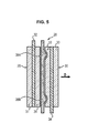
- This assembly 10 comprises an envelope comprising a cylindrical body 12 comprising a lateral wall 14 and a bottom 16 forming an end face of the assembly, and an opening at its end opposite the bottom 16.
- the envelope also comprises a cover 18 having a main face 20 covering the opening of the body 12 and forming the other end face of the assembly and a peripheral skirt 22 intended to follow the upper part of the side wall 14 of the assembly, outside thereof.
- the assembly 10 comprises, inside the envelope, a capacitive element 24 composed of a positive electrode complex 26, two separators 28A, 28B and a negative electrode complex 30 superimposed and then wound.
- the stacking is carried out in the following order: positive electrode complex 26, separator 28A, negative electrode complex 30, separator 28B.
- Each complex 26, 30 comprises in central part a current collector 32, 34 and, on each face of the collector, an electrode layer 31, 33, respectively positive for the complex 26 or negative for the complex 30.
- the electrodes positive and negative also referred to as cathode and anode respectively, comprise a porous activated carbon for storing the charges.
- Current collectors 32; 34 generally made of a metallic material, make it possible to transmit the current thus created to the outside of the storage assembly.
- the separator made of an electrically insulating and porous material, electrically isolates the two electrodes (to avoid short circuits) while allowing the charges to flow between them.
- the separator is made of porous plastic, for example polypropylene.
- a liquid electrolyte is contained in the envelope of the assembly. This electrolyte allows the circulation of charges between two adjacent electrodes.
- each electrode complex of a particular type is connected to an end face of the storage assembly.
- the connection between the collectors 32, 34 and the envelope is in particular carried out using a weld.
- the collectors 32 of the positive electrode therefore exceed the electrode stack at a first end of the stack, in a predetermined direction normal to the direction of superposition, while the collectors 34 of the negative electrode. of the stack protrude at an opposite end, also in the predetermined direction.
- the body 12 and the cover 18 are each made of a conductive material, in particular metal, and form the respective terminals of the assembly.
- the lid forms the positive terminal while the body forms the negative terminal of the assembly.
- the collector 32 associated with the positive electrodes is therefore connected to the cover 18 while the collector 34 associated with the negative electrodes is connected to the bottom 16 of the envelope.
- the body and the lid are electrically insulated by means of a gasket 35 placed between the inner face of the peripheral skirt 22 and the outer face of the side wall 14. This material also helps to seal the assembly and prevent leakage of the electrolyte.
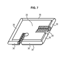
- This set comprises a casing 102 of the type "coffee bag", well known in the trade, which comprises a cylindrical body open at each of these ends 103 but closed on itself at each of these ends to form a sealed envelope.
- a capacitive element 104 comprising four complexes 106A, 106B; 108A, 108B stacked with interposing a separator 110A, 110B, 110C between each pair of adjacent complexes.
- Each positive complex 106A, 106B is placed next to a negative complex 108A, 108B to form an elementary capacitive cell.
- each complex 106, 108 is composed of two electrodes between which is placed a metal current collector protruding electrodes in a predetermined direction.
- the collectors of the positive complexes 106A, 106B protrude from the electrode at a first end of the stack in the predetermined direction while the collectors of the negative complexes 108A, 108B protrude from the electrode at a second end of the stack according to the predetermined direction.
- Separators 110A-110C also protrude from the stack at both ends of the stack in the predetermined direction.
- the collectors of the positive complexes 106A, 106B and the separators 110A-110C at a first end of the stack and the collectors of the negative complexes 108A, 108B and the separators at a second end of the stack. stack are thermo-sealed with the edge of the envelope at this end. The collectors and separators are thus brought together to be in contact at each end 103 of the stack. It should be noted that the collectors and / or the separators are not necessarily heat-sealed.
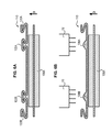
- the separator 28 comprises at each of its ends in the predetermined direction, normal to the superposition direction D, a protuberance 36A, 36B.
- This protuberance is made by locally remelting the plastic material which is constituted by the separator. It is performed continuously along the entire end of the separator. The protrusion therefore extends perpendicularly to the predetermined direction.
- the protuberances 36A, 36B abut against the ends of the adjacent electrodes between which the separator is interposed, if an attempt is made to modify the position of the separator in the predetermined direction.
- this withdrawal in the predetermined direction is prevented by the abutment of the protuberances against the electrodes.
- the capacitive element 24 is inserted into the envelope, it is connected to the body 12 and to the cover 18, the cover 18 and the body 12 are connected and the assembly is impregnated by inserting the electrolyte into the the envelope.
- the positive 26 and negative 30 complexes are identical to those of the figure 3 and will not be detailed.
- the separator 28 however comprises, in replacement of the protuberances 36A, 36B, protuberances 38A, 38B in the portion of the separator 28 located between the electrodes 31, 33.
- These protuberances 38A, 38B are also produced by refounding the material of the separator 28 and are therefore non-porous. They are clamped between the respective electrodes 31, 33 of the positive 26 and negative 30 complexes and are even likely to slightly deform the surface of the electrode. 31, 33.
- protuberances 38A, 38B When the separator 28 is heated, these protuberances 38A, 38B remain in their initial positions because of the clamping exerted thereon by the electrodes 31, 33 and exert a locking preventing the removal of the separator 28 in its central part, located between the protuberances 38A, 38B. These protuberances 38A, 38B extend continuously over the entire dimension of the separator.
- protuberances 38A, 38B opposite the electrodes 31, 33 and preferably in the vicinity of the ends thereof
- They can also be used in combination with protuberances such as 36A, 36B (made on the outside of the ends of the electrodes) in order to distribute the stresses on the separator 28 in case of withdrawal.
- protuberances 38A, 38B facing the electrodes 31, 33 does not prevent the ionic conduction and the ion exchange between two electrodes 31, 33 facing each other since the separator 28 is only remelted locally. The parts of the separator comprising no protuberance therefore remain naturally porous.
- the embodiment of the protuberances from a fold leads to protuberances protruding substantially on one side of the separators.
- the plies and / or the melting modalities of the material may be adapted to make projecting protuberances on the two main faces of the separators, at least substantially symmetrically with respect to the mean plane of the separators.
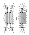
- FIG. 6A to 6E another variant of a method of assembling an energy storage assembly, this assembly being an assembly such as that of the figure 2 in which is placed a capacitive element comprising extreme protuberances such as those of the figure 3 and central protuberances.
- a separator 110 is stacked on a complex 106A, the separator being disposed on the complex 106A so that it protrudes from the electrode on each side thereof in the predetermined direction and has folds 120A, 120B at its ends and folds 122A, 122B in its portion superimposed on the electrode.
- the separator has at least two superimposed layers ( ⁇ -shaped for the folds 122A and 122B and S-shaped for the folds 120A and 120B).
- the separator 110 is heated to the right of the folds 122A, 122B.
- the rollers 40, 42 are applied above the separator 110 in the superposition direction D of the various elements, so as to locally heat it and form a non-porous protuberance 138A, 138B in place of the folds 122A, 122B.
- the presence of the folds facilitates the formation of the protuberances by providing a local surplus of material.
- the electrode is heated in this embodiment but that the melting temperature thereof is higher than the melting temperature of the separator.
- a negative complex 108A is then stacked above the separator 110A and another separator 110B, which is heated, etc. to form a stack as shown on the Figure 6C .
- This stack is then slid into an envelope 102, open at both ends, as indicated in this figure.
- the two ends of the envelope are closed so that the separators 110A-110C and the collector of a type of complex (ie, either positive or negative) is interposed between the edge portions of the envelope 102. one of its ends.
- the separators 110A, 110B, 110C are withdrawn at their ends (not important since the protuberances 138A, 138B located between the electrodes hold the separator in place over a large part of its length). Then they remelt locally at their ends to form a respective protuberance 136A, 136B.
- the envelope 102 made of aluminum, and the electrodes 106, 108 do not melt at the melting temperature of the separators 110A, 110B, 110C. Once these separator 110A, 110B, 110C remelted, increasing temperature and pressure at the ends 103 to heat seal the two ends of the envelope by compressing the stack of collectors and separators against each other and solder the different elements of stacking through this. This is achieved using pairs of rollers referenced 40A, 40B and 42A, 42B on the figures 6 attached.
- the thickness of the protrusion 36, 38, 136, 138 is at least 1.2 times the thickness of the adjacent zone of the separator 28 free. protrusion, very preferably greater than 1.5 times the thickness of the adjacent zone of the separator free protrusion, to ensure the previously described mechanical locking effect.
- the thickness of the separator 28 is generally between 5 and 40 microns, advantageously of the order of 30 microns.
- the capacitive element may be a stacked element but arranged in an envelope of a different type from what has been described.
- the separators and / or the collectors are not necessarily connected, or not necessarily all connected, with the envelope at its ends.
- the protuberances may also be provided on the separator on portions thereof in the predetermined direction, and not the entire of its dimension in this direction. They are then constituted by a plurality of clusters separated by portions devoid of clusters.
- the protrusion may also be provided on the separator in more than one direction and could for example be formed zig-zag. This is particularly the case when the separator belongs to a stacked capacitive element.
- the protuberance can be arranged in at least two directions, each being normal to the direction of superposition.
- the protuberances 36 form a continuous frame which extends all around a separator.
- the separator is folded so as to surround an electrode and comprises a protuberance in the vicinity of an end retained between a first and a second complex, and a protuberance in the vicinity of the other end retained between the second and a third complex.
- the electrode may not be integral with a collector or that a complex may comprise only a collector and a single electrode layer.
- the winding step is carried out before the step of heating and forming the protuberance, or that, in the case of a stacked together, the separator is not sealed with the envelope or has no folds for example.
- a separator placed in a wound element may also comprise protuberances in its superimposed portion with the electrode and / or folds for the formation of the protuberances.
- the separator may be in a configuration different from those described.
Landscapes
- Chemical & Material Sciences (AREA)
- Chemical Kinetics & Catalysis (AREA)
- Electrochemistry (AREA)
- General Chemical & Material Sciences (AREA)
- Engineering & Computer Science (AREA)
- Power Engineering (AREA)
- Microelectronics & Electronic Packaging (AREA)
- Electric Double-Layer Capacitors Or The Like (AREA)
- Secondary Cells (AREA)
Applications Claiming Priority (1)
| Application Number | Priority Date | Filing Date | Title |
|---|---|---|---|
| FR1351949A FR3003074B1 (fr) | 2013-03-05 | 2013-03-05 | Element capacitif comprenant un separateur comprenant des protuberances interdisant son retrait |
Publications (2)
| Publication Number | Publication Date |
|---|---|
| EP2775492A1 true EP2775492A1 (de) | 2014-09-10 |
| EP2775492B1 EP2775492B1 (de) | 2018-05-23 |
Family
ID=48613842
Family Applications (1)
| Application Number | Title | Priority Date | Filing Date |
|---|---|---|---|
| EP14156775.0A Not-in-force EP2775492B1 (de) | 2013-03-05 | 2014-02-26 | Kapazitives Element, das einen Separator mit Protuberanzen umfasst, die sein Herausziehen verhindern |
Country Status (4)
| Country | Link |
|---|---|
| EP (1) | EP2775492B1 (de) |
| ES (1) | ES2682926T3 (de) |
| FR (1) | FR3003074B1 (de) |
| HK (1) | HK1201981A1 (de) |
Families Citing this family (1)
| Publication number | Priority date | Publication date | Assignee | Title |
|---|---|---|---|---|
| US20230062789A1 (en) * | 2019-12-27 | 2023-03-02 | Zeon Corporation | Laminate for secondary battery, secondary battery, and method of producing laminate for secondary battery |
Citations (7)
| Publication number | Priority date | Publication date | Assignee | Title |
|---|---|---|---|---|
| GB2031300A (en) * | 1978-08-30 | 1980-04-23 | Grace W R & Co | Method of producing battery separators |
| US20060141350A1 (en) * | 2003-06-13 | 2006-06-29 | Daniel Dreyer | Separator material for forming a separator for an acid accumulator |
| WO2007080469A1 (en) * | 2006-01-10 | 2007-07-19 | Toyota Jidosha Kabushiki Kaisha | Fuel cell stack with integrated alignment means |
| EP2086044A2 (de) * | 2008-02-04 | 2009-08-05 | Fuji Jukogyo Kabushiki Kaisha | Elektrische Speichervorrichtung |
| US20100129720A1 (en) * | 2006-10-30 | 2010-05-27 | Kentaro Sako | Polyolefin microporous membrane |
| FR2970594A1 (fr) * | 2011-01-13 | 2012-07-20 | Batscap Sa | Ensemble de stockage d'energie electrique a element empile en accordeon |
| JP2012209072A (ja) * | 2011-03-29 | 2012-10-25 | Nec Corp | 電極積層型電池の電極積層体、および該電極積層体の製造方法 |
-
2013
- 2013-03-05 FR FR1351949A patent/FR3003074B1/fr not_active Expired - Fee Related
-
2014
- 2014-02-26 EP EP14156775.0A patent/EP2775492B1/de not_active Not-in-force
- 2014-02-26 ES ES14156775.0T patent/ES2682926T3/es active Active
-
2015
- 2015-03-06 HK HK15102304.0A patent/HK1201981A1/xx not_active IP Right Cessation
Patent Citations (7)
| Publication number | Priority date | Publication date | Assignee | Title |
|---|---|---|---|---|
| GB2031300A (en) * | 1978-08-30 | 1980-04-23 | Grace W R & Co | Method of producing battery separators |
| US20060141350A1 (en) * | 2003-06-13 | 2006-06-29 | Daniel Dreyer | Separator material for forming a separator for an acid accumulator |
| WO2007080469A1 (en) * | 2006-01-10 | 2007-07-19 | Toyota Jidosha Kabushiki Kaisha | Fuel cell stack with integrated alignment means |
| US20100129720A1 (en) * | 2006-10-30 | 2010-05-27 | Kentaro Sako | Polyolefin microporous membrane |
| EP2086044A2 (de) * | 2008-02-04 | 2009-08-05 | Fuji Jukogyo Kabushiki Kaisha | Elektrische Speichervorrichtung |
| FR2970594A1 (fr) * | 2011-01-13 | 2012-07-20 | Batscap Sa | Ensemble de stockage d'energie electrique a element empile en accordeon |
| JP2012209072A (ja) * | 2011-03-29 | 2012-10-25 | Nec Corp | 電極積層型電池の電極積層体、および該電極積層体の製造方法 |
Also Published As
| Publication number | Publication date |
|---|---|
| ES2682926T3 (es) | 2018-09-24 |
| FR3003074A1 (fr) | 2014-09-12 |
| FR3003074B1 (fr) | 2016-09-02 |
| HK1201981A1 (en) | 2015-09-11 |
| EP2775492B1 (de) | 2018-05-23 |
Similar Documents
| Publication | Publication Date | Title |
|---|---|---|
| FR2471659A1 (fr) | Condensateur electrique a double couche du type a auto-support | |
| EP0310075B1 (de) | Aktivierbarer elektrochemischer Lithium-Oxyhalogenid-Generator | |
| EP2699376B1 (de) | Verfahren und vorrichtung zum reibrührschweissen einer elektrischen energiespeicheranordnung | |
| CA2631864A1 (fr) | Systeme de stockage d'energie electrique | |
| WO2020245521A1 (fr) | Film conducteur composite pour la réalisation d'accumulateurs d'énergie électrique, procédé de réalisation d'un tel film, et accumulateur électrique utilisant un tel film | |
| FR2928035A1 (fr) | Connexion electrique pour accumulateur de courant. | |
| EP2775492B1 (de) | Kapazitives Element, das einen Separator mit Protuberanzen umfasst, die sein Herausziehen verhindern | |
| WO2007068810A1 (fr) | Pile a combustible avec collecteurs de courant integres a l'electrolyte solide et procede de fabrication d'une telle pile a combustible. | |
| EP0350366B1 (de) | Festelektrolytkondensator, insbesondere aus Tantal, mit einer eingebauten Schmelzsicherung | |
| EP3035411B1 (de) | Verbindungsverfahren in einem akkumulator, und so verbundener akkumulator | |
| EP0587710B1 (de) | Alkali-akkumulator mit bipolarer elektrode und verfahren zu dessen herstellung | |
| EP2724408B1 (de) | Gasdiffusionselektrode von hoher kapazität | |
| EP2775491B1 (de) | Kapazitives Element, das einen auf einen Komplex geklebten Separator umfasst | |
| FR2824667A1 (fr) | Connectique interne pour generateur electrochimique de forte puissance | |
| WO2013117654A1 (fr) | Couvercle pour ensemble de stockage d'energie, ensemble de stockage d'energie comportant ledit couvercle, et procede de fabrication d'un tel ensemble de stockage d'energie | |
| EP3985769A1 (de) | Batteriemodul mit stapel von weich verpackten akkumulatoren, die in festen halterungen zwischen ihnen durch knappen oder klippen und stützklemmen in druckkontakt mit den akkumulatorklemmen gehäuset werden. | |
| FR3016241A1 (fr) | Ensemble de stockage d'energie electrique, et procede de fabrication associe | |
| CA3062030A1 (fr) | Procede d'assemblage pour pile a combustible | |
| FR3054403A1 (fr) | Vitrage avec element electriquement conducteur et sa connexion electrique | |
| FR3059159A1 (fr) | Electrode pour faisceau electrochimique d'un accumulateur metal-ion a forte densite d'energie, accumulateur cylindrique ou prismatique associe | |
| WO2023117952A1 (fr) | Elément de batterie et procédé de fabrication associé | |
| EP4342018A1 (de) | Elektrochemisches element für eine batterie und entsprechende batterie | |
| FR3106939A1 (fr) | Element electrochimique de type pochette de format semi-circulaire | |
| FR3109673A1 (fr) | Composant à reliefs de rétention de matière active pour accumulateur d’énergie électrique, accumulateur d’énergie électrique utilisant le composant et procédé de fabrication | |
| EP0459873A1 (de) | Festelektrolytkondensator, insbesondere aus Tantal, mit gestanzter eingebauter Schmelzsicherung und Verfahren zu seiner Herstellung |
Legal Events
| Date | Code | Title | Description |
|---|---|---|---|
| PUAI | Public reference made under article 153(3) epc to a published international application that has entered the european phase |
Free format text: ORIGINAL CODE: 0009012 |
|
| 17P | Request for examination filed |
Effective date: 20140226 |
|
| AK | Designated contracting states |
Kind code of ref document: A1 Designated state(s): AL AT BE BG CH CY CZ DE DK EE ES FI FR GB GR HR HU IE IS IT LI LT LU LV MC MK MT NL NO PL PT RO RS SE SI SK SM TR |
|
| AX | Request for extension of the european patent |
Extension state: BA ME |
|
| RIN1 | Information on inventor provided before grant (corrected) |
Inventor name: VIGNERAS, ERWAN |
|
| REG | Reference to a national code |
Ref country code: HK Ref legal event code: DE Ref document number: 1201981 Country of ref document: HK |
|
| REG | Reference to a national code |
Ref country code: DE Ref legal event code: R079 Ref document number: 602014025749 Country of ref document: DE Free format text: PREVIOUS MAIN CLASS: H01G0009020000 Ipc: H01G0011520000 |
|
| GRAP | Despatch of communication of intention to grant a patent |
Free format text: ORIGINAL CODE: EPIDOSNIGR1 |
|
| STAA | Information on the status of an ep patent application or granted ep patent |
Free format text: STATUS: GRANT OF PATENT IS INTENDED |
|
| RIC1 | Information provided on ipc code assigned before grant |
Ipc: H01M 2/14 20060101ALI20171107BHEP Ipc: H01G 11/52 20130101AFI20171107BHEP Ipc: H01M 2/18 20060101ALI20171107BHEP Ipc: H01G 9/02 20060101ALI20171107BHEP Ipc: H01M 2/16 20060101ALI20171107BHEP |
|
| INTG | Intention to grant announced |
Effective date: 20171124 |
|
| GRAS | Grant fee paid |
Free format text: ORIGINAL CODE: EPIDOSNIGR3 |
|
| GRAJ | Information related to disapproval of communication of intention to grant by the applicant or resumption of examination proceedings by the epo deleted |
Free format text: ORIGINAL CODE: EPIDOSDIGR1 |
|
| GRAL | Information related to payment of fee for publishing/printing deleted |
Free format text: ORIGINAL CODE: EPIDOSDIGR3 |
|
| STAA | Information on the status of an ep patent application or granted ep patent |
Free format text: STATUS: REQUEST FOR EXAMINATION WAS MADE |
|
| GRAR | Information related to intention to grant a patent recorded |
Free format text: ORIGINAL CODE: EPIDOSNIGR71 |
|
| STAA | Information on the status of an ep patent application or granted ep patent |
Free format text: STATUS: GRANT OF PATENT IS INTENDED |
|
| GRAA | (expected) grant |
Free format text: ORIGINAL CODE: 0009210 |
|
| STAA | Information on the status of an ep patent application or granted ep patent |
Free format text: STATUS: THE PATENT HAS BEEN GRANTED |
|
| INTC | Intention to grant announced (deleted) | ||
| INTG | Intention to grant announced |
Effective date: 20180411 |
|
| AK | Designated contracting states |
Kind code of ref document: B1 Designated state(s): AL AT BE BG CH CY CZ DE DK EE ES FI FR GB GR HR HU IE IS IT LI LT LU LV MC MK MT NL NO PL PT RO RS SE SI SK SM TR |
|
| REG | Reference to a national code |
Ref country code: GB Ref legal event code: FG4D Free format text: NOT ENGLISH |
|
| REG | Reference to a national code |
Ref country code: CH Ref legal event code: EP |
|
| REG | Reference to a national code |
Ref country code: IE Ref legal event code: FG4D Free format text: LANGUAGE OF EP DOCUMENT: FRENCH |
|
| REG | Reference to a national code |
Ref country code: AT Ref legal event code: REF Ref document number: 1002169 Country of ref document: AT Kind code of ref document: T Effective date: 20180615 |
|
| REG | Reference to a national code |
Ref country code: DE Ref legal event code: R096 Ref document number: 602014025749 Country of ref document: DE |
|
| REG | Reference to a national code |
Ref country code: CH Ref legal event code: NV Representative=s name: MICHELI AND CIE SA, CH |
|
| REG | Reference to a national code |
Ref country code: ES Ref legal event code: FG2A Ref document number: 2682926 Country of ref document: ES Kind code of ref document: T3 Effective date: 20180924 |
|
| REG | Reference to a national code |
Ref country code: NL Ref legal event code: MP Effective date: 20180523 |
|
| REG | Reference to a national code |
Ref country code: LT Ref legal event code: MG4D |
|
| PG25 | Lapsed in a contracting state [announced via postgrant information from national office to epo] |
Ref country code: BG Free format text: LAPSE BECAUSE OF FAILURE TO SUBMIT A TRANSLATION OF THE DESCRIPTION OR TO PAY THE FEE WITHIN THE PRESCRIBED TIME-LIMIT Effective date: 20180823 Ref country code: FI Free format text: LAPSE BECAUSE OF FAILURE TO SUBMIT A TRANSLATION OF THE DESCRIPTION OR TO PAY THE FEE WITHIN THE PRESCRIBED TIME-LIMIT Effective date: 20180523 Ref country code: NO Free format text: LAPSE BECAUSE OF FAILURE TO SUBMIT A TRANSLATION OF THE DESCRIPTION OR TO PAY THE FEE WITHIN THE PRESCRIBED TIME-LIMIT Effective date: 20180823 Ref country code: SE Free format text: LAPSE BECAUSE OF FAILURE TO SUBMIT A TRANSLATION OF THE DESCRIPTION OR TO PAY THE FEE WITHIN THE PRESCRIBED TIME-LIMIT Effective date: 20180523 Ref country code: LT Free format text: LAPSE BECAUSE OF FAILURE TO SUBMIT A TRANSLATION OF THE DESCRIPTION OR TO PAY THE FEE WITHIN THE PRESCRIBED TIME-LIMIT Effective date: 20180523 |
|
| PG25 | Lapsed in a contracting state [announced via postgrant information from national office to epo] |
Ref country code: LV Free format text: LAPSE BECAUSE OF FAILURE TO SUBMIT A TRANSLATION OF THE DESCRIPTION OR TO PAY THE FEE WITHIN THE PRESCRIBED TIME-LIMIT Effective date: 20180523 Ref country code: NL Free format text: LAPSE BECAUSE OF FAILURE TO SUBMIT A TRANSLATION OF THE DESCRIPTION OR TO PAY THE FEE WITHIN THE PRESCRIBED TIME-LIMIT Effective date: 20180523 Ref country code: RS Free format text: LAPSE BECAUSE OF FAILURE TO SUBMIT A TRANSLATION OF THE DESCRIPTION OR TO PAY THE FEE WITHIN THE PRESCRIBED TIME-LIMIT Effective date: 20180523 Ref country code: HR Free format text: LAPSE BECAUSE OF FAILURE TO SUBMIT A TRANSLATION OF THE DESCRIPTION OR TO PAY THE FEE WITHIN THE PRESCRIBED TIME-LIMIT Effective date: 20180523 Ref country code: GR Free format text: LAPSE BECAUSE OF FAILURE TO SUBMIT A TRANSLATION OF THE DESCRIPTION OR TO PAY THE FEE WITHIN THE PRESCRIBED TIME-LIMIT Effective date: 20180824 |
|
| REG | Reference to a national code |
Ref country code: AT Ref legal event code: MK05 Ref document number: 1002169 Country of ref document: AT Kind code of ref document: T Effective date: 20180523 |
|
| PG25 | Lapsed in a contracting state [announced via postgrant information from national office to epo] |
Ref country code: EE Free format text: LAPSE BECAUSE OF FAILURE TO SUBMIT A TRANSLATION OF THE DESCRIPTION OR TO PAY THE FEE WITHIN THE PRESCRIBED TIME-LIMIT Effective date: 20180523 Ref country code: PL Free format text: LAPSE BECAUSE OF FAILURE TO SUBMIT A TRANSLATION OF THE DESCRIPTION OR TO PAY THE FEE WITHIN THE PRESCRIBED TIME-LIMIT Effective date: 20180523 Ref country code: SK Free format text: LAPSE BECAUSE OF FAILURE TO SUBMIT A TRANSLATION OF THE DESCRIPTION OR TO PAY THE FEE WITHIN THE PRESCRIBED TIME-LIMIT Effective date: 20180523 Ref country code: AT Free format text: LAPSE BECAUSE OF FAILURE TO SUBMIT A TRANSLATION OF THE DESCRIPTION OR TO PAY THE FEE WITHIN THE PRESCRIBED TIME-LIMIT Effective date: 20180523 Ref country code: DK Free format text: LAPSE BECAUSE OF FAILURE TO SUBMIT A TRANSLATION OF THE DESCRIPTION OR TO PAY THE FEE WITHIN THE PRESCRIBED TIME-LIMIT Effective date: 20180523 Ref country code: CZ Free format text: LAPSE BECAUSE OF FAILURE TO SUBMIT A TRANSLATION OF THE DESCRIPTION OR TO PAY THE FEE WITHIN THE PRESCRIBED TIME-LIMIT Effective date: 20180523 Ref country code: RO Free format text: LAPSE BECAUSE OF FAILURE TO SUBMIT A TRANSLATION OF THE DESCRIPTION OR TO PAY THE FEE WITHIN THE PRESCRIBED TIME-LIMIT Effective date: 20180523 |
|
| REG | Reference to a national code |
Ref country code: DE Ref legal event code: R097 Ref document number: 602014025749 Country of ref document: DE |
|
| PG25 | Lapsed in a contracting state [announced via postgrant information from national office to epo] |
Ref country code: SM Free format text: LAPSE BECAUSE OF FAILURE TO SUBMIT A TRANSLATION OF THE DESCRIPTION OR TO PAY THE FEE WITHIN THE PRESCRIBED TIME-LIMIT Effective date: 20180523 |
|
| PLBE | No opposition filed within time limit |
Free format text: ORIGINAL CODE: 0009261 |
|
| STAA | Information on the status of an ep patent application or granted ep patent |
Free format text: STATUS: NO OPPOSITION FILED WITHIN TIME LIMIT |
|
| 26N | No opposition filed |
Effective date: 20190226 |
|
| PG25 | Lapsed in a contracting state [announced via postgrant information from national office to epo] |
Ref country code: SI Free format text: LAPSE BECAUSE OF FAILURE TO SUBMIT A TRANSLATION OF THE DESCRIPTION OR TO PAY THE FEE WITHIN THE PRESCRIBED TIME-LIMIT Effective date: 20180523 |
|
| PG25 | Lapsed in a contracting state [announced via postgrant information from national office to epo] |
Ref country code: MC Free format text: LAPSE BECAUSE OF FAILURE TO SUBMIT A TRANSLATION OF THE DESCRIPTION OR TO PAY THE FEE WITHIN THE PRESCRIBED TIME-LIMIT Effective date: 20180523 Ref country code: LU Free format text: LAPSE BECAUSE OF NON-PAYMENT OF DUE FEES Effective date: 20190226 |
|
| REG | Reference to a national code |
Ref country code: BE Ref legal event code: MM Effective date: 20190228 |
|
| REG | Reference to a national code |
Ref country code: IE Ref legal event code: MM4A |
|
| PG25 | Lapsed in a contracting state [announced via postgrant information from national office to epo] |
Ref country code: AL Free format text: LAPSE BECAUSE OF FAILURE TO SUBMIT A TRANSLATION OF THE DESCRIPTION OR TO PAY THE FEE WITHIN THE PRESCRIBED TIME-LIMIT Effective date: 20180523 |
|
| PG25 | Lapsed in a contracting state [announced via postgrant information from national office to epo] |
Ref country code: IE Free format text: LAPSE BECAUSE OF NON-PAYMENT OF DUE FEES Effective date: 20190226 |
|
| PG25 | Lapsed in a contracting state [announced via postgrant information from national office to epo] |
Ref country code: BE Free format text: LAPSE BECAUSE OF NON-PAYMENT OF DUE FEES Effective date: 20190228 |
|
| PG25 | Lapsed in a contracting state [announced via postgrant information from national office to epo] |
Ref country code: TR Free format text: LAPSE BECAUSE OF FAILURE TO SUBMIT A TRANSLATION OF THE DESCRIPTION OR TO PAY THE FEE WITHIN THE PRESCRIBED TIME-LIMIT Effective date: 20180523 |
|
| PGFP | Annual fee paid to national office [announced via postgrant information from national office to epo] |
Ref country code: DE Payment date: 20200211 Year of fee payment: 7 Ref country code: IT Payment date: 20200212 Year of fee payment: 7 Ref country code: GB Payment date: 20200219 Year of fee payment: 7 |
|
| PGFP | Annual fee paid to national office [announced via postgrant information from national office to epo] |
Ref country code: CH Payment date: 20200225 Year of fee payment: 7 |
|
| PG25 | Lapsed in a contracting state [announced via postgrant information from national office to epo] |
Ref country code: PT Free format text: LAPSE BECAUSE OF FAILURE TO SUBMIT A TRANSLATION OF THE DESCRIPTION OR TO PAY THE FEE WITHIN THE PRESCRIBED TIME-LIMIT Effective date: 20180924 Ref country code: MT Free format text: LAPSE BECAUSE OF FAILURE TO SUBMIT A TRANSLATION OF THE DESCRIPTION OR TO PAY THE FEE WITHIN THE PRESCRIBED TIME-LIMIT Effective date: 20180523 |
|
| PGFP | Annual fee paid to national office [announced via postgrant information from national office to epo] |
Ref country code: FR Payment date: 20200207 Year of fee payment: 7 |
|
| PGFP | Annual fee paid to national office [announced via postgrant information from national office to epo] |
Ref country code: ES Payment date: 20200331 Year of fee payment: 7 |
|
| PG25 | Lapsed in a contracting state [announced via postgrant information from national office to epo] |
Ref country code: CY Free format text: LAPSE BECAUSE OF FAILURE TO SUBMIT A TRANSLATION OF THE DESCRIPTION OR TO PAY THE FEE WITHIN THE PRESCRIBED TIME-LIMIT Effective date: 20180523 |
|
| PG25 | Lapsed in a contracting state [announced via postgrant information from national office to epo] |
Ref country code: IS Free format text: LAPSE BECAUSE OF FAILURE TO SUBMIT A TRANSLATION OF THE DESCRIPTION OR TO PAY THE FEE WITHIN THE PRESCRIBED TIME-LIMIT Effective date: 20180923 |
|
| PG25 | Lapsed in a contracting state [announced via postgrant information from national office to epo] |
Ref country code: HU Free format text: LAPSE BECAUSE OF FAILURE TO SUBMIT A TRANSLATION OF THE DESCRIPTION OR TO PAY THE FEE WITHIN THE PRESCRIBED TIME-LIMIT; INVALID AB INITIO Effective date: 20140226 |
|
| REG | Reference to a national code |
Ref country code: DE Ref legal event code: R119 Ref document number: 602014025749 Country of ref document: DE |
|
| GBPC | Gb: european patent ceased through non-payment of renewal fee |
Effective date: 20210226 |
|
| PG25 | Lapsed in a contracting state [announced via postgrant information from national office to epo] |
Ref country code: LI Free format text: LAPSE BECAUSE OF NON-PAYMENT OF DUE FEES Effective date: 20210228 Ref country code: CH Free format text: LAPSE BECAUSE OF NON-PAYMENT OF DUE FEES Effective date: 20210228 |
|
| PG25 | Lapsed in a contracting state [announced via postgrant information from national office to epo] |
Ref country code: GB Free format text: LAPSE BECAUSE OF NON-PAYMENT OF DUE FEES Effective date: 20210226 Ref country code: FR Free format text: LAPSE BECAUSE OF NON-PAYMENT OF DUE FEES Effective date: 20210228 Ref country code: DE Free format text: LAPSE BECAUSE OF NON-PAYMENT OF DUE FEES Effective date: 20210901 |
|
| PG25 | Lapsed in a contracting state [announced via postgrant information from national office to epo] |
Ref country code: IT Free format text: LAPSE BECAUSE OF NON-PAYMENT OF DUE FEES Effective date: 20210226 |
|
| REG | Reference to a national code |
Ref country code: ES Ref legal event code: FD2A Effective date: 20220513 |
|
| PG25 | Lapsed in a contracting state [announced via postgrant information from national office to epo] |
Ref country code: MK Free format text: LAPSE BECAUSE OF FAILURE TO SUBMIT A TRANSLATION OF THE DESCRIPTION OR TO PAY THE FEE WITHIN THE PRESCRIBED TIME-LIMIT Effective date: 20180523 |
|
| PG25 | Lapsed in a contracting state [announced via postgrant information from national office to epo] |
Ref country code: ES Free format text: LAPSE BECAUSE OF NON-PAYMENT OF DUE FEES Effective date: 20210227 |