EP2775487A1 - Reactor and production method thereof - Google Patents
Reactor and production method thereof Download PDFInfo
- Publication number
- EP2775487A1 EP2775487A1 EP11875123.9A EP11875123A EP2775487A1 EP 2775487 A1 EP2775487 A1 EP 2775487A1 EP 11875123 A EP11875123 A EP 11875123A EP 2775487 A1 EP2775487 A1 EP 2775487A1
- Authority
- EP
- European Patent Office
- Prior art keywords
- resin
- reactor
- bobbin
- coil
- slit
- Prior art date
- Legal status (The legal status is an assumption and is not a legal conclusion. Google has not performed a legal analysis and makes no representation as to the accuracy of the status listed.)
- Withdrawn
Links
- 238000004519 manufacturing process Methods 0.000 title claims description 8
- 239000011347 resin Substances 0.000 claims abstract description 70
- 229920005989 resin Polymers 0.000 claims abstract description 70
- 238000000034 method Methods 0.000 claims description 6
- 238000005266 casting Methods 0.000 abstract description 13
- 238000004804 winding Methods 0.000 description 7
- 239000000463 material Substances 0.000 description 5
- 239000011810 insulating material Substances 0.000 description 4
- 238000009499 grossing Methods 0.000 description 3
- 238000010125 resin casting Methods 0.000 description 3
- 238000007789 sealing Methods 0.000 description 3
- 125000006850 spacer group Chemical group 0.000 description 3
- 238000002347 injection Methods 0.000 description 2
- 239000007924 injection Substances 0.000 description 2
- 238000003780 insertion Methods 0.000 description 2
- 230000037431 insertion Effects 0.000 description 2
- 229910000859 α-Fe Inorganic materials 0.000 description 2
- 239000000853 adhesive Substances 0.000 description 1
- 230000001070 adhesive effect Effects 0.000 description 1
- 230000004075 alteration Effects 0.000 description 1
- PNEYBMLMFCGWSK-UHFFFAOYSA-N aluminium oxide Inorganic materials [O-2].[O-2].[O-2].[Al+3].[Al+3] PNEYBMLMFCGWSK-UHFFFAOYSA-N 0.000 description 1
- 239000000919 ceramic Substances 0.000 description 1
- 230000001419 dependent effect Effects 0.000 description 1
- 238000009413 insulation Methods 0.000 description 1
- 239000000696 magnetic material Substances 0.000 description 1
- 238000012986 modification Methods 0.000 description 1
- 230000004048 modification Effects 0.000 description 1
- 230000002265 prevention Effects 0.000 description 1
- 239000011265 semifinished product Substances 0.000 description 1
Images


Classifications
-
- H—ELECTRICITY
- H01—ELECTRIC ELEMENTS
- H01F—MAGNETS; INDUCTANCES; TRANSFORMERS; SELECTION OF MATERIALS FOR THEIR MAGNETIC PROPERTIES
- H01F41/00—Apparatus or processes specially adapted for manufacturing or assembling magnets, inductances or transformers; Apparatus or processes specially adapted for manufacturing materials characterised by their magnetic properties
- H01F41/02—Apparatus or processes specially adapted for manufacturing or assembling magnets, inductances or transformers; Apparatus or processes specially adapted for manufacturing materials characterised by their magnetic properties for manufacturing cores, coils, or magnets
- H01F41/04—Apparatus or processes specially adapted for manufacturing or assembling magnets, inductances or transformers; Apparatus or processes specially adapted for manufacturing materials characterised by their magnetic properties for manufacturing cores, coils, or magnets for manufacturing coils
- H01F41/10—Connecting leads to windings
-
- H—ELECTRICITY
- H01—ELECTRIC ELEMENTS
- H01F—MAGNETS; INDUCTANCES; TRANSFORMERS; SELECTION OF MATERIALS FOR THEIR MAGNETIC PROPERTIES
- H01F37/00—Fixed inductances not covered by group H01F17/00
-
- H—ELECTRICITY
- H01—ELECTRIC ELEMENTS
- H01F—MAGNETS; INDUCTANCES; TRANSFORMERS; SELECTION OF MATERIALS FOR THEIR MAGNETIC PROPERTIES
- H01F27/00—Details of transformers or inductances, in general
- H01F27/28—Coils; Windings; Conductive connections
- H01F27/32—Insulating of coils, windings, or parts thereof
- H01F27/324—Insulation between coil and core, between different winding sections, around the coil; Other insulation structures
- H01F27/325—Coil bobbins
-
- H—ELECTRICITY
- H01—ELECTRIC ELEMENTS
- H01F—MAGNETS; INDUCTANCES; TRANSFORMERS; SELECTION OF MATERIALS FOR THEIR MAGNETIC PROPERTIES
- H01F5/00—Coils
- H01F5/04—Arrangements of electric connections to coils, e.g. leads
-
- H—ELECTRICITY
- H01—ELECTRIC ELEMENTS
- H01F—MAGNETS; INDUCTANCES; TRANSFORMERS; SELECTION OF MATERIALS FOR THEIR MAGNETIC PROPERTIES
- H01F17/00—Fixed inductances of the signal type
- H01F17/04—Fixed inductances of the signal type with magnetic core
- H01F17/045—Fixed inductances of the signal type with magnetic core with core of cylindric geometry and coil wound along its longitudinal axis, i.e. rod or drum core
- H01F2017/046—Fixed inductances of the signal type with magnetic core with core of cylindric geometry and coil wound along its longitudinal axis, i.e. rod or drum core helical coil made of flat wire, e.g. with smaller extension of wire cross section in the direction of the longitudinal axis
-
- Y—GENERAL TAGGING OF NEW TECHNOLOGICAL DEVELOPMENTS; GENERAL TAGGING OF CROSS-SECTIONAL TECHNOLOGIES SPANNING OVER SEVERAL SECTIONS OF THE IPC; TECHNICAL SUBJECTS COVERED BY FORMER USPC CROSS-REFERENCE ART COLLECTIONS [XRACs] AND DIGESTS
- Y10—TECHNICAL SUBJECTS COVERED BY FORMER USPC
- Y10T—TECHNICAL SUBJECTS COVERED BY FORMER US CLASSIFICATION
- Y10T29/00—Metal working
- Y10T29/49—Method of mechanical manufacture
- Y10T29/49002—Electrical device making
- Y10T29/4902—Electromagnet, transformer or inductor
Definitions
- the present application relates to a reactor (a passive element utilizing a coil) and its manufacturing method.
- the reactor is also referred to as an "inductor”.
- hybrid and electric vehicles have been fully put into practical use and have been gaining popularity. These vehicles use a motor as a power source and have a reactor in their electric circuit for the motor in many cases.
- the reactor is used in an inverter or voltage converter for smoothing an electric current.
- the main body of the reactor is configured of a core and a winding wire (a coil) wound onto the core. Ferrite is often used as the core.
- the reactor may or may not contain a bobbin onto which the coil (the winding wire) is wound.
- Many reactors for smoothing a large current are generally provided with the bobbin.
- the core is passed through the bobbin having flanges at both sides and the coil (the winding wire) is wound between the flanges of the bobbin.
- Such reactors are disclosed in Patent documents 1 to 3 for example.
- the whole of the coil is covered by an insulating material for insulation.
- the cover of the coil is advantageously formed by resin casting from a cost viewpoint.
- a casting equipment in which the resin is filled so as to surround the lead may have a complicated structure. For example, in such equipment, positions of the lead and a die need to be precisely adjusted so that the lead is enclosed in the closed die. If a cavity through which the lead is passed is extended, the resin may leak from around the lead upon casting the resin. It is provided herein a reactor which reduces a possibility of leakage of resin into the vicinity of the lead. It is also provided herein a technique which allows production of the reactor at low cost while reducing the possibility of leakage of resin into the vicinity of the lead.
- the technique disclosed herein surrounds a part (or all) of a lead of a coil (a winding wire) with resin before casting the resin, for which a flange of a bobbin is utilized.
- the bobbin is often made of resin, and therefore is an insulating material. An end of the coil comes into contact with the flange of the bobbin.
- a slit is provided on a flange of the bobbin, and a lead of the coil extends through the slit.
- the coil is covered by resin from one flange to the other flange of the bobbin. More specifically, the resin contacts both flanges as well as covers the coil from one flange to the other.
- the reactor is provided in which the whole of the coil is covered by the resin while reducing the possibility of leakage of the resin into the vicinity of the lead.
- Providing the slit at the flange for holding the lead can eliminate the need for providing a space for enclosing the lead in the die for casting the resin.
- the above reactor allows the resin being produced with a simple die.
- the above reactor does not require a complicated die or production equipment and therefore can be manufactured at low cost.
- a window may be provided on the resin and a portion of the coil may be exposed through the window.
- the above reactor can be suitably manufactured by the following steps. First, a bobbin containing a core is prepared which is divided into two parts along a longitudinal direction of the bobbin. Next, each of the parts of the bobbin is inserted from each side of the coil. Then, resin is formed so as to cover the coil between flanges of the bobbin. As described above, at least one flange of the bobbin is provided with a slit. A lead of the coil is drawn out from the slit while inserting the parts of the bobbin into the coil. Upon casting the resin, an opening of the slit is covered by a cover.
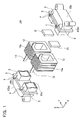
- FIG. 1 shows an exploded perspective view of a reactor 100
- FIG. 2 shows a perspective view of a bobbin
- FIG. 3 shows a perspective view of the reactor (semifinished, without resin). The resin is omitted in FIG. 1
- FIG. 4 shows an enlarged plan view around a slit provided on a flange.
- FIG. 5 shows a perspective view of the completed reactor.
- the reactor 100 may for example be used for smoothing an electric current in an electric vehicle.
- the reactor 100 is for a large electric current and a rectangular wire is used as a winding wire.
- the rectangular wire is a conductive wire having a rectangular cross section.
- the reactor 100 is now outlined.
- a ring-shaped core is covered by a bobbin 2 made of resin. Winding wires are wound at two positions of the bobbin 2 to form two coils 10a and 10b (see FIG. 3 ).
- the coils 10a and 10b are formed between flanges 3 at both sides of the bobbin ( FIG. 3 ).
- the coils 10a and 10b are covered by resin 30 (a resin cover portion) between the flanges 3 ( FIG. 5 ).
- Each lead 12 of each coil is drawn out between the flange 3 and resin 30.
- the reactor 100 is illustrated in detail hereinbelow.
- the ring-shaped bobbin 2 is divided into two parts 2a and 2b roughly at a center in a longitudinal direction (an x-axis direction). Accordingly, each part 2a or 2b has a c-shape.
- Cores 22a and 22b having a c-shape are embedded in the bobbin parts 2a and 2b, respectively.
- the cores 22a and 22b are made of ferrite. When the bobbin parts 2a and 2b face each other, the cores 22a and 22b also face each other, thereby forming the core having the ring shape.
- the flanges 3 are provided on both sides of the bobbin 2.
- the wires are wound between the flanges 3 on both sides to form the coils 10a and 10b.
- the flanges 3 define a position of each coil. In other words, the flanges 3 are positioned at both sides of each coil.
- the flange 3 is provided with slits 5.
- the leads 12 of the coils 10a and 10b pass through the slits 5.
- Ribs 4 extend from the flange 3 which flank the slit 5.
- Ribs 4 secure a height of the slit 5 corresponding to a width of the lead 12 having the rectangular cross section. Namely, a size of the cross section of the slit 5 is approximately the same as a size of the cross section of the lead 12 of the coil.
- the reactor 100 is illustrated according to manufacturing procedures.
- the bobbin 2 which is divided into two parts along the longitudinal direction is prepared ( FIG. 2 ).
- the bobbin part 2a is formed by placing the c-shaped core 22a in a die and injecting resin into a cavity around the core 22a.
- the bobbin part 2a containing the core is formed by resin injection casting.
- the other bobbin part 2b is produced in a similar manner.
- the bobbin parts 2a and 2b are then respectively inserted from the respective sides of the coils 10a and 10b.
- spacers 21 are placed between two bobbin parts 2a and 2b.
- the spacers 21 are made of a non-magnetic material.
- a material for the spacers 21 is, for example, alumina ceramics.
- the bobbins 2a and 2b are connected by an adhesive.
- the leads 12 of the coils pass through the slits 5 provided on the flanges 3 of the bobbins 2a and 2b.
- the size of the slit 5 is approximately the same as the cross sectional size of the lead 12, so that the lead 12 fits into the slit 5 substantially without space.
- FIG. 4 shows the plan view of the vicinity of the slit 5.
- corners 5a at an inner side (a side facing the coil 10a) of the slit 5 curve from an inner surface of the flange toward side walls of the slit.
- the lead 12 enters from one side of the slit 5 along a curved corner 5a of the slit to the other side of the slit 5. In other words, the lead 12 curves along the curved corner 5a of the slit.
- a semifinished reactor 90 is obtained as shown in FIG. 3 .
- the semifinished product 90 is then placed in another die, resin is filled between the flanges 3 on both sides, thereby forming the resin 30 ( FIG. 5 ).
- the resin 30 covers above the rib 4 and lead 12. Namely, the resin 30 blocks the opening of the slit 5.
- a symbol 31 in FIG. 5 represents a sealing part that covers above the rib 4 and lead 12. The vicinity of each lead 12 is sealed by the slit 5 at the flange 3 and the sealing part 31 of the resin 30. Thereby the reactor 100 is completed.
- the reactor 100 is a device in which the bobbin 2 made of resin is formed so as to cover the ring-shaped cores 22a and 22b, and the coils 10a and 10b (winding wires) are wound between the flanges 3 at both sides of the bobbin.
- the coils 10a and 10b are covered by the flanges 3 of the bobbin 2 and the resin 30.
- the leads 12 of the coils 10a and 10b are drawn out from the slits 5 provided on the flanges 3.
- the openings from which the leads 12 are drawn out are surrounded and sealed by the slits 5 and the resin 30. Prior to casting the resin 30, the leads 12 fit into the slits 5.
- the reactor 100 can be obtained which reduces a possibility of leakage of resin in the vicinity of the leads 12.
- the corners 5a at the inner side of the slit 5 curve, and the lead 12 enters into the slit 5 curving along a curved corner (see FIG. 4 ).
- one face of the lead 12 attaches firmly to a wall surface of the slit (the curved corner 5a).
- This configuration contributes to prevention of the leakage of molten resin.
- the corner 5a at the inner side of the slit 5 advantageously curves, the lead 12 can be easily extended through the slit 5.
- a side with a broader space between the curved corner 5a and the lead 12 is filled with molten resin.
- a step of manufacturing the bobbin part 2a containing the core 22a therein and the bobbin part 2b containing the core 22b therein may be referred to as a primary casting, and a step of injection casting the resin 30 may be referred to as a secondary casting.
- the bobbin 2 and the resin 30 are made of the same material. Accordingly, the flanges 3 (ribs 4) can fuse with the resin 30 (sealing parts 31).
- the rectangular wire is used. Most portions of the rectangular wire having a large width are surrounded by the slits 5 of the flanges 3, so that the resin 30 needs to cover only a small part (the upper side of the rectangular wire). Accordingly the die for forming the resin 30 does not need to comprise a space where the rectangular wire is sandwiched. Therefore the resin 30 of the reactor can be formed with the die having a simple shape.
- FIG. 6 shows a reactor 200 of the second embodiment.
- the resin is omitted in FIG. 6 .
- each flange 3 is provided with ribs 204, and each rib 204 (flange 3) is provided with a closed slit 205 which surrounds the whole circumference of a lead 12.
- the size of the slit 205 is approximately the same as the cross sectional size of the lead 12.
- Other configurations are the same as those of the reactor 100 of the first embodiment.
- the whole circumference of the lead 12 is surrounded by the closed slit 205, and leakage of molten resin through a side of the lead 12 upon casting the resin is further effectively prevented.
- FIG. 7 shows a reactor 300 of the third embodiment.
- windows 341 are provided on resin 330, and a portion of the coil 10a and a portion of the coil 10b are exposed through the windows 341.
- a heat-transfer material is subsequently applied to each exposed portion in order to release heat of the coil 10a (10b) through the heat-transfer material. Because the heat-transfer material is also an insulating material, the whole coil is covered by the insulating material when completed.
Landscapes
- Engineering & Computer Science (AREA)
- Power Engineering (AREA)
- Manufacturing & Machinery (AREA)
- Insulating Of Coils (AREA)
Abstract
Description
- The present application relates to a reactor (a passive element utilizing a coil) and its manufacturing method. The reactor is also referred to as an "inductor".
- In recent years, hybrid and electric vehicles have been fully put into practical use and have been gaining popularity. These vehicles use a motor as a power source and have a reactor in their electric circuit for the motor in many cases. The reactor is used in an inverter or voltage converter for smoothing an electric current. The main body of the reactor is configured of a core and a winding wire (a coil) wound onto the core. Ferrite is often used as the core.
- The reactor may or may not contain a bobbin onto which the coil (the winding wire) is wound. Many reactors for smoothing a large current are generally provided with the bobbin. The core is passed through the bobbin having flanges at both sides and the coil (the winding wire) is wound between the flanges of the bobbin. Such reactors are disclosed in Patent documents 1 to 3 for example. In all these reactors, the whole of the coil is covered by an insulating material for insulation. The cover of the coil is advantageously formed by resin casting from a cost viewpoint.
-
- Patent document 1: Japanese Patent Application Publication No.
2010-245457 - Patent document 2: Japanese Patent Application Publication No.
2011-100842 - Patent document 3: Japanese Patent Application Publication No.
2010-245154 - When a coil is covered by resin, a lead of the coil needs to be drawn out from the resin. A casting equipment in which the resin is filled so as to surround the lead may have a complicated structure. For example, in such equipment, positions of the lead and a die need to be precisely adjusted so that the lead is enclosed in the closed die. If a cavity through which the lead is passed is extended, the resin may leak from around the lead upon casting the resin. It is provided herein a reactor which reduces a possibility of leakage of resin into the vicinity of the lead. It is also provided herein a technique which allows production of the reactor at low cost while reducing the possibility of leakage of resin into the vicinity of the lead.
- The technique disclosed herein surrounds a part (or all) of a lead of a coil (a winding wire) with resin before casting the resin, for which a flange of a bobbin is utilized. The bobbin is often made of resin, and therefore is an insulating material. An end of the coil comes into contact with the flange of the bobbin. According to a novel reactor disclosed herein, a slit is provided on a flange of the bobbin, and a lead of the coil extends through the slit. The coil is covered by resin from one flange to the other flange of the bobbin. More specifically, the resin contacts both flanges as well as covers the coil from one flange to the other. When casting the resin, resin needs to be filled only at an opening of the slit. When the resin is filled into a die, the flange holding the lead in its slit can prevent the leakage of the resin. Accordingly, the reactor is provided in which the whole of the coil is covered by the resin while reducing the possibility of leakage of the resin into the vicinity of the lead.
- Providing the slit at the flange for holding the lead can eliminate the need for providing a space for enclosing the lead in the die for casting the resin.
- The above reactor allows the resin being produced with a simple die. The above reactor does not require a complicated die or production equipment and therefore can be manufactured at low cost.
- It is not necessary that the whole coil is completely covered by the resin. A window may be provided on the resin and a portion of the coil may be exposed through the window.
- The above reactor can be suitably manufactured by the following steps. First, a bobbin containing a core is prepared which is divided into two parts along a longitudinal direction of the bobbin. Next, each of the parts of the bobbin is inserted from each side of the coil. Then, resin is formed so as to cover the coil between flanges of the bobbin. As described above, at least one flange of the bobbin is provided with a slit. A lead of the coil is drawn out from the slit while inserting the parts of the bobbin into the coil. Upon casting the resin, an opening of the slit is covered by a cover.
- Further improvements according to the present invention are illustrated by embodiments of the present invention.
-
-
FIG. 1 is an exploded perspective view of a reactor (without resin); -
FIG. 2 is a perspective view of a bobbin; -
FIG. 3 is a perspective view of the reactor (without resin); -
FIG. 4 is an enlarged plan view around a slit of a flange; -
FIG. 5 is a perspective view of the reactor (with resin); -
FIG. 6 is a perspective view of a reactor (without resin) of a second embodiment; and -
FIG. 7 is a perspective view of a reactor of a third embodiment. - (First embodiment) A reactor of the first embodiment is illustrated with referring to the figures.
FIG. 1 shows an exploded perspective view of areactor 100,FIG. 2 shows a perspective view of a bobbin andFIG. 3 shows a perspective view of the reactor (semifinished, without resin). The resin is omitted inFIG. 1 .FIG. 4 shows an enlarged plan view around a slit provided on a flange.FIG. 5 shows a perspective view of the completed reactor. Thereactor 100 may for example be used for smoothing an electric current in an electric vehicle. Thereactor 100 is for a large electric current and a rectangular wire is used as a winding wire. The rectangular wire is a conductive wire having a rectangular cross section. - The
reactor 100 is now outlined. In thereactor 100, a ring-shaped core is covered by abobbin 2 made of resin. Winding wires are wound at two positions of thebobbin 2 to form twocoils FIG. 3 ). Thecoils flanges 3 at both sides of the bobbin (FIG. 3 ). Thecoils FIG. 5 ). Eachlead 12 of each coil is drawn out between theflange 3 andresin 30. - The
reactor 100 is illustrated in detail hereinbelow. As shown inFIG. 2 , the ring-shapedbobbin 2 is divided into twoparts part -
Cores bobbin parts cores bobbin parts cores - On both sides of the
bobbin 2, theflanges 3 are provided. The wires are wound between theflanges 3 on both sides to form thecoils flanges 3 define a position of each coil. In other words, theflanges 3 are positioned at both sides of each coil. Theflange 3 is provided withslits 5. As shown inFIG. 3 , theleads 12 of thecoils slits 5.Ribs 4 extend from theflange 3 which flank theslit 5.Ribs 4 secure a height of theslit 5 corresponding to a width of thelead 12 having the rectangular cross section. Namely, a size of the cross section of theslit 5 is approximately the same as a size of the cross section of thelead 12 of the coil. - The
reactor 100 is illustrated according to manufacturing procedures. First of all, thebobbin 2 which is divided into two parts along the longitudinal direction is prepared (FIG. 2 ). Thebobbin part 2a is formed by placing the c-shapedcore 22a in a die and injecting resin into a cavity around thecore 22a. Namely, thebobbin part 2a containing the core is formed by resin injection casting. Theother bobbin part 2b is produced in a similar manner. - As shown in
FIG. 1 , thebobbin parts coils bobbin parts coils spacers 21 are placed between twobobbin parts spacers 21 are made of a non-magnetic material. A material for thespacers 21 is, for example, alumina ceramics. - The
bobbins slits 5 provided on theflanges 3 of thebobbins slit 5 is approximately the same as the cross sectional size of thelead 12, so that thelead 12 fits into theslit 5 substantially without space. -
FIG. 4 shows the plan view of the vicinity of theslit 5. As shown inFIG. 4 ,corners 5a at an inner side (a side facing thecoil 10a) of theslit 5 curve from an inner surface of the flange toward side walls of the slit. When thebobbin part 2a (2b) is inserted into thecoil 10a (10b), thelead 12 enters from one side of theslit 5 along acurved corner 5a of the slit to the other side of theslit 5. In other words, thelead 12 curves along thecurved corner 5a of the slit. - After insertion of the
bobbin parts coils semifinished reactor 90 is obtained as shown inFIG. 3 . Thesemifinished product 90 is then placed in another die, resin is filled between theflanges 3 on both sides, thereby forming the resin 30 (FIG. 5 ). As shown inFIG. 5 , theresin 30 covers above therib 4 and lead 12. Namely, theresin 30 blocks the opening of theslit 5. Asymbol 31 inFIG. 5 represents a sealing part that covers above therib 4 and lead 12. The vicinity of each lead 12 is sealed by theslit 5 at theflange 3 and the sealingpart 31 of theresin 30. Thereby thereactor 100 is completed. - Features of the
reactor 100 are as follows. Thereactor 100 is a device in which thebobbin 2 made of resin is formed so as to cover the ring-shapedcores coils flanges 3 at both sides of the bobbin. Thecoils flanges 3 of thebobbin 2 and theresin 30. The leads 12 of thecoils slits 5 provided on theflanges 3. The openings from which the leads 12 are drawn out are surrounded and sealed by theslits 5 and theresin 30. Prior to casting theresin 30, theleads 12 fit into theslits 5. Therefore it is not necessary to fill molten resin to the whole circumference of each lead 12 upon resin casting, and the molten resin seldom leaks from around theleads 12 upon resin casting. According to the above technique, thereactor 100 can be obtained which reduces a possibility of leakage of resin in the vicinity of the leads 12. - Particularly, the
corners 5a at the inner side of the slit 5 (a corner facing the coil) curve, and thelead 12 enters into theslit 5 curving along a curved corner (seeFIG. 4 ). Thus, one face of thelead 12 attaches firmly to a wall surface of the slit (thecurved corner 5a). This configuration contributes to prevention of the leakage of molten resin. Further, because thecorner 5a at the inner side of theslit 5 advantageously curves, thelead 12 can be easily extended through theslit 5. In addition, a side with a broader space between thecurved corner 5a and thelead 12 is filled with molten resin. - A step of manufacturing the
bobbin part 2a containing the core 22a therein and thebobbin part 2b containing the core 22b therein may be referred to as a primary casting, and a step of injection casting theresin 30 may be referred to as a secondary casting. Thebobbin 2 and theresin 30 are made of the same material. Accordingly, the flanges 3 (ribs 4) can fuse with the resin 30 (sealing parts 31). - In the
reactor 100, the rectangular wire is used. Most portions of the rectangular wire having a large width are surrounded by theslits 5 of theflanges 3, so that theresin 30 needs to cover only a small part (the upper side of the rectangular wire). Accordingly the die for forming theresin 30 does not need to comprise a space where the rectangular wire is sandwiched. Therefore theresin 30 of the reactor can be formed with the die having a simple shape. - (Second embodiment)
FIG. 6 shows areactor 200 of the second embodiment. The resin is omitted inFIG. 6 . In thereactor 200, eachflange 3 is provided withribs 204, and each rib 204 (flange 3) is provided with aclosed slit 205 which surrounds the whole circumference of alead 12. In thereactor 200 as well, the size of theslit 205 is approximately the same as the cross sectional size of thelead 12. Other configurations are the same as those of thereactor 100 of the first embodiment. In thereactor 200 of the second embodiment, the whole circumference of thelead 12 is surrounded by theclosed slit 205, and leakage of molten resin through a side of thelead 12 upon casting the resin is further effectively prevented. - (Third embodiment)
FIG. 7 shows areactor 300 of the third embodiment. In thereactor 300,windows 341 are provided onresin 330, and a portion of thecoil 10a and a portion of thecoil 10b are exposed through thewindows 341. A heat-transfer material is subsequently applied to each exposed portion in order to release heat of thecoil 10a (10b) through the heat-transfer material. Because the heat-transfer material is also an insulating material, the whole coil is covered by the insulating material when completed. - Representative and non-limiting specific examples of the present invention have been illustrated in detail with referring to the drawings. The detailed description intends to illustrate the details for practicing the preferred embodiments of the present invention to a person skilled in the art and does not intend to limit the scope of the present invention. The disclosed additional features and inventions can be used with or without other features and inventions in order to provide a further improved reactor or a manufacturing method thereof.
- The combinations of the features and steps disclosed hereinabove are not essential for practicing the present invention in its broadest meaning and are described merely for particularly illustrating representative specific embodiments of the present invention. Further, it is not required that the various features of the representative specific embodiments and the various features described in independent and dependent claims are combined in the same manner as described in the specific embodiments or in the same order as listed herein.
- All the features described in the specification and /or claims are intended to be disclosed, apart from the configurations of the features described in embodiments and/or claims, individually and independently from each other as limitations to the original disclosure at the filing and the claimed specific matters. All descriptions on numerical ranges and groups or sets are intended to disclose the configurations in between as the limitations to the original disclosure at the time of filing and the claimed specific matters.
- Specific embodiments of the present invention have been illustrated hereinabove in detail. However, they are merely examples and do not limit the scope of the claims. The technique described in the claims comprises various modification and alterations of the above specific embodiments. The technical elements illustrated in the specification and drawings exert technical values alone or in various combinations and are not limited to the combination described in the claims at the time of filing. The techniques exemplified in the specification or drawings can achieve multiple purposes simultaneously and are technically valuable by merely achieving one of the purposes.
Claims (5)
- A reactor in which a coil is wound on a bobbin, wherein:a slit is provided on a flange of the bobbin;a lead of the coil extends through the slit; andthe coil is covered by resin from one flange to the other flange of the bobbin.
- The reactor of claim 1 wherein a corner of the slit facing the coil is curved.
- The reactor of claim 2 wherein the lead curves along the corner of the slit.
- The reactor of any one of claims 1 to 3 wherein:a window is provided on the resin covering the coil, anda portion of the coil is exposed through the window.
- A method of manufacturing a reactor, the method comprising:preparing a bobbin divided into two parts along a longitudinal direction of the bobbin;inserting each of the parts of the bobbin from each side of a coil; andforming resin so as to cover the coil between flanges of the bobbin;wherein:a slit is provided on at least one of the flanges; anda lead of the coil is passed through the slit while inserting the parts of the bobbin.
Applications Claiming Priority (1)
| Application Number | Priority Date | Filing Date | Title |
|---|---|---|---|
| PCT/JP2011/075472 WO2013065183A1 (en) | 2011-11-04 | 2011-11-04 | Reactor and production method thereof |
Publications (2)
| Publication Number | Publication Date |
|---|---|
| EP2775487A1 true EP2775487A1 (en) | 2014-09-10 |
| EP2775487A4 EP2775487A4 (en) | 2015-03-04 |
Family
ID=48191572
Family Applications (1)
| Application Number | Title | Priority Date | Filing Date |
|---|---|---|---|
| EP11875123.9A Withdrawn EP2775487A4 (en) | 2011-11-04 | 2011-11-04 | REACTOR AND METHOD FOR PRODUCING THE SAME |
Country Status (5)
| Country | Link |
|---|---|
| US (1) | US20140230238A1 (en) |
| EP (1) | EP2775487A4 (en) |
| JP (1) | JP5365745B1 (en) |
| CN (1) | CN103229257A (en) |
| WO (1) | WO2013065183A1 (en) |
Cited By (3)
| Publication number | Priority date | Publication date | Assignee | Title |
|---|---|---|---|---|
| CN104485200A (en) * | 2014-12-19 | 2015-04-01 | 上海楚尧电子科技有限公司 | Electric reactor |
| EP4184533A1 (en) * | 2021-11-17 | 2023-05-24 | SMA Solar Technology AG | Filter-choke, production method thereof and electrical device |
| WO2023088672A1 (en) * | 2021-11-17 | 2023-05-25 | Sma Solar Technology Ag | Filter-choke, production method thereof and electrical device |
Families Citing this family (16)
| Publication number | Priority date | Publication date | Assignee | Title |
|---|---|---|---|---|
| JP5917996B2 (en) * | 2012-04-24 | 2016-05-18 | 株式会社タムラ製作所 | Reactor |
| JP6343141B2 (en) * | 2013-11-22 | 2018-06-13 | 株式会社タムラ製作所 | Reactor |
| JP6278250B2 (en) * | 2013-08-28 | 2018-02-14 | 日立金属株式会社 | Reactor |
| JP6153900B2 (en) * | 2014-07-31 | 2017-06-28 | 株式会社タムラ製作所 | Reactor |
| JP6106646B2 (en) * | 2014-09-25 | 2017-04-05 | 株式会社タムラ製作所 | Reactor |
| JP6106645B2 (en) * | 2014-09-25 | 2017-04-05 | 株式会社タムラ製作所 | Reactor |
| JP6570876B2 (en) * | 2015-05-21 | 2019-09-04 | 株式会社タムラ製作所 | Reactor |
| JP6491065B2 (en) * | 2015-09-07 | 2019-03-27 | トヨタ自動車株式会社 | Reactor |
| JP2018006460A (en) * | 2016-06-29 | 2018-01-11 | 株式会社トーキン | Line filter |
| CN107786021B (en) * | 2016-08-29 | 2019-10-11 | 光宝电子(广州)有限公司 | Insulating sleeve with around wire work |
| JP6745442B2 (en) | 2016-10-28 | 2020-08-26 | パナソニックIpマネジメント株式会社 | Manufacturing method of wiring integrated resin pipe |
| JP7017076B2 (en) * | 2017-12-25 | 2022-02-08 | トヨタ自動車株式会社 | Reactor |
| JP7049207B2 (en) * | 2018-07-31 | 2022-04-06 | 株式会社デンソー | Reactor manufacturing method |
| JP2020141025A (en) * | 2019-02-27 | 2020-09-03 | トヨタ自動車株式会社 | Reactor |
| KR102724003B1 (en) * | 2022-07-13 | 2024-10-30 | 용인전자 주식회사 | Inductor |
| FR3143185B1 (en) * | 2022-12-08 | 2025-01-10 | Valeo Eautomotive France Sas | Electronic component, including three-phase transformer for isolated voltage converter |
Family Cites Families (18)
| Publication number | Priority date | Publication date | Assignee | Title |
|---|---|---|---|---|
| JP2569556Y2 (en) * | 1993-06-30 | 1998-04-28 | ティーディーケイ株式会社 | High current choke coil |
| US6144280A (en) * | 1996-11-29 | 2000-11-07 | Taiyo Yuden Co., Ltd. | Wire wound electronic component and method of manufacturing the same |
| JP3844170B2 (en) * | 1998-05-08 | 2006-11-08 | Tdk株式会社 | Box noise filter |
| JP2002291186A (en) * | 2001-03-23 | 2002-10-04 | Nissan Motor Co Ltd | Flat wire winding structure and winding method |
| US6598824B2 (en) * | 2001-11-20 | 2003-07-29 | Trombetta, Llc | Electrical and mechanical coil system for dual and single action solenoids |
| CN1894755B (en) * | 2003-12-10 | 2011-11-16 | 株式会社田村制作所 | Transformer |
| JP4513805B2 (en) * | 2004-03-09 | 2010-07-28 | パナソニック株式会社 | Trance |
| JPWO2006016554A1 (en) * | 2004-08-10 | 2008-05-01 | 株式会社タムラ製作所 | Reactor |
| JP2007180140A (en) * | 2005-12-27 | 2007-07-12 | Denso Corp | Magnetic parts |
| JP2007200926A (en) * | 2006-01-23 | 2007-08-09 | Tdk Corp | Coil part |
| JP4740774B2 (en) * | 2006-03-15 | 2011-08-03 | 株式会社多賀製作所 | Winding terminal processing method and apparatus |
| EP2315220B1 (en) * | 2008-08-22 | 2016-03-30 | Sumitomo Electric Industries, Ltd. | Reactor component and reactor |
| JP5234517B2 (en) * | 2009-03-05 | 2013-07-10 | 住友電気工業株式会社 | Reactor, reactor manufacturing method, and converter |
| JP2010245154A (en) | 2009-04-02 | 2010-10-28 | Denso Corp | Reactor |
| JP5344158B2 (en) | 2009-04-09 | 2013-11-20 | 住友電気工業株式会社 | Reactor, reactor bobbin, and converter |
| JP5240860B2 (en) | 2009-11-05 | 2013-07-17 | Necトーキン株式会社 | Magnetic element |
| JP5428996B2 (en) * | 2010-03-29 | 2014-02-26 | 株式会社豊田自動織機 | Reactor |
| JP5932245B2 (en) * | 2011-06-06 | 2016-06-08 | 株式会社タムラ製作所 | Bobbin for coil device and coil device |
-
2011
- 2011-11-04 WO PCT/JP2011/075472 patent/WO2013065183A1/en not_active Ceased
- 2011-11-04 US US14/237,650 patent/US20140230238A1/en not_active Abandoned
- 2011-11-04 EP EP11875123.9A patent/EP2775487A4/en not_active Withdrawn
- 2011-11-04 CN CN201180057353XA patent/CN103229257A/en active Pending
- 2011-11-04 JP JP2012531584A patent/JP5365745B1/en not_active Expired - Fee Related
Cited By (3)
| Publication number | Priority date | Publication date | Assignee | Title |
|---|---|---|---|---|
| CN104485200A (en) * | 2014-12-19 | 2015-04-01 | 上海楚尧电子科技有限公司 | Electric reactor |
| EP4184533A1 (en) * | 2021-11-17 | 2023-05-24 | SMA Solar Technology AG | Filter-choke, production method thereof and electrical device |
| WO2023088672A1 (en) * | 2021-11-17 | 2023-05-25 | Sma Solar Technology Ag | Filter-choke, production method thereof and electrical device |
Also Published As
| Publication number | Publication date |
|---|---|
| WO2013065183A1 (en) | 2013-05-10 |
| CN103229257A (en) | 2013-07-31 |
| US20140230238A1 (en) | 2014-08-21 |
| EP2775487A4 (en) | 2015-03-04 |
| JP5365745B1 (en) | 2013-12-11 |
| JPWO2013065183A1 (en) | 2015-04-02 |
Similar Documents
| Publication | Publication Date | Title |
|---|---|---|
| EP2775487A1 (en) | Reactor and production method thereof | |
| CN104871269B (en) | Reactor, transducer and power inverter | |
| KR101854386B1 (en) | Coil insulating structure of electromagnetic motor stator | |
| US10530211B2 (en) | Coil winding component and rotary electric machine | |
| US10665386B2 (en) | Reactor and reactor manufacturing method | |
| US20190019613A1 (en) | Hollow toroidal magnetic power unit | |
| US20140218158A1 (en) | Reactor | |
| RU2280935C2 (en) | Electric motor stator assembly and method for its manufacture | |
| JP2014192516A (en) | Reactor | |
| KR102302913B1 (en) | Core case unit, coil component, and method for producing coil component | |
| US20090152976A1 (en) | Dynamo-electrical machine with tooth-wound coils | |
| EP2551864A1 (en) | Method of manufacture for encased coil body and encased coil body | |
| US20140218156A1 (en) | Reactor | |
| EP2669911B1 (en) | Reactor and reactor apparatus | |
| EP2980814B1 (en) | Winding component | |
| US20130120099A1 (en) | Transformer | |
| US11948718B2 (en) | Reactor | |
| JP5246411B2 (en) | Reactor, converter, and reactor manufacturing method | |
| JP7733796B2 (en) | Molded coils and reactors | |
| EP2660833B1 (en) | Ignition coil | |
| JP7355398B2 (en) | Contactless charging coil unit and its manufacturing method | |
| US20180268992A1 (en) | Three-phase reactor having insulating structure | |
| JP6075678B2 (en) | Composite magnetic core, reactor and power supply | |
| JP2017183476A (en) | Coil unit, wireless power feeding device, wireless power receiving device, and wireless power transmission device | |
| JP5900741B2 (en) | Composite magnetic core, reactor and power supply |
Legal Events
| Date | Code | Title | Description |
|---|---|---|---|
| PUAI | Public reference made under article 153(3) epc to a published international application that has entered the european phase |
Free format text: ORIGINAL CODE: 0009012 |
|
| 17P | Request for examination filed |
Effective date: 20130610 |
|
| AK | Designated contracting states |
Kind code of ref document: A1 Designated state(s): AL AT BE BG CH CY CZ DE DK EE ES FI FR GB GR HR HU IE IS IT LI LT LU LV MC MK MT NL NO PL PT RO RS SE SI SK SM TR |
|
| DAX | Request for extension of the european patent (deleted) | ||
| A4 | Supplementary search report drawn up and despatched |
Effective date: 20150130 |
|
| RIC1 | Information provided on ipc code assigned before grant |
Ipc: H01F 27/32 20060101ALI20150126BHEP Ipc: H01F 5/04 20060101ALI20150126BHEP Ipc: H01F 37/00 20060101AFI20150126BHEP Ipc: H01F 41/10 20060101ALI20150126BHEP Ipc: H01F 17/04 20060101ALI20150126BHEP |
|
| RIC1 | Information provided on ipc code assigned before grant |
Ipc: H01F 41/10 20060101ALI20150826BHEP Ipc: H01F 5/04 20060101ALI20150826BHEP Ipc: H01F 37/00 20060101AFI20150826BHEP Ipc: H01F 17/04 20060101ALI20150826BHEP Ipc: H01F 27/32 20060101ALI20150826BHEP |
|
| GRAP | Despatch of communication of intention to grant a patent |
Free format text: ORIGINAL CODE: EPIDOSNIGR1 |
|
| INTG | Intention to grant announced |
Effective date: 20151009 |
|
| STAA | Information on the status of an ep patent application or granted ep patent |
Free format text: STATUS: THE APPLICATION IS DEEMED TO BE WITHDRAWN |
|
| 18D | Application deemed to be withdrawn |
Effective date: 20160220 |