EP2660833B1 - Ignition coil - Google Patents
Ignition coil Download PDFInfo
- Publication number
- EP2660833B1 EP2660833B1 EP13165719.9A EP13165719A EP2660833B1 EP 2660833 B1 EP2660833 B1 EP 2660833B1 EP 13165719 A EP13165719 A EP 13165719A EP 2660833 B1 EP2660833 B1 EP 2660833B1
- Authority
- EP
- European Patent Office
- Prior art keywords
- core
- ignition coil
- over
- legs
- molding material
- Prior art date
- Legal status (The legal status is an assumption and is not a legal conclusion. Google has not performed a legal analysis and makes no representation as to the accuracy of the status listed.)
- Active
Links
Images


Classifications
-
- H—ELECTRICITY
- H01—ELECTRIC ELEMENTS
- H01F—MAGNETS; INDUCTANCES; TRANSFORMERS; SELECTION OF MATERIALS FOR THEIR MAGNETIC PROPERTIES
- H01F27/00—Details of transformers or inductances, in general
- H01F27/02—Casings
- H01F27/022—Encapsulation
-
- H—ELECTRICITY
- H01—ELECTRIC ELEMENTS
- H01F—MAGNETS; INDUCTANCES; TRANSFORMERS; SELECTION OF MATERIALS FOR THEIR MAGNETIC PROPERTIES
- H01F38/00—Adaptations of transformers or inductances for specific applications or functions
- H01F38/12—Ignition, e.g. for IC engines
Definitions
- the present invention relates to an ignition coil for developing a spark firing voltage that is applied to one or more spark plugs of an internal combustion engine.
- Ignition coils are known for use in connection with an internal combustion engine such as an automobile engine.
- Ignition coils typically include a primary winding, a secondary winding, and a magnetic circuit.
- the magnetic circuit conventionally may include a central core extending along an axis and located radially inward of the primary and secondary windings and magnetically coupled thereto.
- a C-shaped high permeance structure is included to provide a high permeance magnetic return path.
- the high permeance structure may include a base section from which a pair of legs extends.
- the central core is placed between the legs such that the axis of the core extends through the legs of the high permeance structure and such that at least one end of the core is spaced apart from the leg to which it is adjacent to define an air gap.
- the primary winding, secondary winding, core and high permeance structure are contained in a case formed of an electrical insulating material.
- the case is filled with an insulating resin or the like for insulating purposes.
- insulating resin that fills the air gap may be subject to stress from the core during operation of the ignition coil. This stress may lead to undesired performance of the ignition coil.
- the invention consists on an ignition coil for an internal combustion engine includes a magnetically-permeable core extending along a core longitudinal axis, the core having a pair of end surfaces on axially-opposite ends thereof.
- the ignition coil also includes a primary winding disposed outward of the core, a secondary winding disposed outward of the primary winding, and a structure comprising magnetically-permeable steel laminations having a base and a pair of legs, the structure defining a magnetic return path.
- the core is disposed between the pair of legs such that the core longitudinal axis extends through the legs and the end surfaces face toward the legs and at least one of the end surfaces of the core is spaced apart from a respective one of the legs to define an air gap.
- the core has a radial cross-section that is non-circular in shape and is substantially oval in radial cross-section.
- the substantially oval shape in radial cross-section includes a pair of straight sides that are parallel to each other and connected at each end by arcuate ends that oppose each other.
- the structure is over-molded with an over-molding material such that the over-molding material fills at least a portion of the air gap.
- the over-molding material is an elastomeric polymer.
- the over-molding material defines a recessed region within at least one of the end surfaces of the core is received.
- the recessed region which is located on one of the legs, includes an air gap setting window through said over-molding material to expose said structure.
- the recessed region is defined by a lip.
- the lip follows a portion of the perimeter of at least one of the end surfaces of the core.
- the lip substantially prevents movement in three directions in a plane defined by the region.
- a first direction of the three directions is parallel to a width of the structure, the width being defined by the sum of the steel laminations.
- a second direction of the three directions is opposite to the first direction; and a third direction of the three directions is perpendicular to the first and second directions and in a direction toward said base.
- the lip prevents movement of the core in a fourth direction in the plane, wherein the fourth direction is opposite to the third direction.
- the sum of the steel laminations defines a width of the structure and wherein the core includes:
- the dimension of the core along the major axis is greater than a dimension of the core along said minor axis.
- the at least one of the legs includes a face that faces toward the core and is tapered from a thicker section that is proximal to the base to a thinner section that is distal from the base.
- Each of the legs includes a face that is that faces toward the core and is tapered from a thicker section that is proximal to the base to a thinner section that is distal from the base.
- the face of one of the legs is free of the over-molding material such that the core is in intimate contact with the face.
- the face of the other legs includes the over-molding material that fills at least the portion of the air gap.
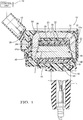
- FIG. 1 is a simplified cross-section view of an ignition coil 10.
- Ignition coil 10 may be controlled by a control unit 12 or the like.
- Ignition coil 10 is configured for connection to a spark plug 14 that is in threaded engagement with a spark plug opening (not shown) in an internal combustion engine (also not shown).
- Ignition coil 10 is configured to output a high-voltage (HV) output to spark plug 14, as shown.
- HV high-voltage
- control unit 12 One ignition coil 10 may be provided per spark plug 14.
- Ignition coil 10 may include a magnetically-permeable core 16, a magnetically-permeable structure 18 configured to provide a high permeance magnetic return path which has a base section 20 and a pair of legs 22 and 24, a primary winding spool 26, a primary winding 28, a quantity of encapsulant 30 such as an epoxy potting material, a secondary winding spool 32, a secondary winding 34, a case 36, a low-voltage (LV) connector body 38 having primary terminals 40 (only one primary terminal 40 is visible in the figures due to being hidden behind primary terminal 40 shown in Fig. 1 ), and a high-voltage (HV) tower 42 having a high-voltage (HV) terminal 44.
- LV low-voltage
- core 16 extends along a core longitudinal axis A and is generally oval in overall shape in radial cross-section as shown in Fig. 2 , which is a radial cross-section view of core 16.
- Core 16 includes an upper end surface 46 at one axial end and a lower end surface 48 at the other axial end which is opposite of upper end surface 46.
- Core 16 may comprise laminated steel plates 50 1 , 50 2 ... 50 n as shown in Fig. 2 .
- core 16 may comprise compression molded insulated iron particles rather than laminated steel plates 50. Core 16 will be described in more detail later.
- primary winding spool 26 is configured to receive and retain primary winding 28.
- Primary winding spool 26 is disposed adjacent to and radially outward of core 16 and is preferably in coaxial relationship therewith.
- Primary winding spool 26 may comprise any one of a number of conventional spool configurations known to those of ordinary skill in the art.
- primary winding spool 26 is configured to receive one continuous primary winding.
- Primary winding spool 26 may be formed generally of electrical insulating material having properties suitable for use in a relatively high temperature environment.
- primary winding spool 26 may comprise plastic material such as PPO/PS (e.g., NORYL® available from General Electric) or polybutylene terephthalate (PBT) thermoplastic polyester. It should be understood that there are a variety of alternative materials that may be used for primary winding spool 26.
- plastic material such as PPO/PS (e.g., NORYL® available from General Electric) or polybutylene terephthalate (PBT) thermoplastic polyester.
- PPO/PS polybutylene terephthalate
- PBT polybutylene terephthalate
- Primary winding 28 as described above, is wound onto primary winding spool 26.
- Primary winding 28 includes first and second ends that are connected to the primary terminals 40 in LV connector body 38.
- Primary winding 28 is configured to carry a primary current I P for charging ignition coil 10 upon control of control unit 12.
- Primary winding 28 may comprise copper, insulated magnet wire, with a size typically between about 20-23 AWG.
- Secondary winding spool 32 is configured to receive and retain secondary winding 34. Secondary winding spool 32 is disposed adjacent to and radially outward of the central components comprising core 16, primary winding spool 26 and primary winding 28 and, preferably, is in coaxial relationship therewith. Secondary winding spool 32 may comprise any one of a number of conventional spool configurations known to those of ordinary skill in the art. In the illustrated embodiment, secondary winding spool 32 is configured for use with a segmented winding strategy where a plurality of axially spaced ribs forms a plurality of channels therebetween for accepting the windings.
- Secondary winding spool 32 may be formed generally of electrical insulating material having properties suitable for use in a relatively high temperature environment.
- Secondary winding spool 32 may comprise plastic material such as PPO/PS (e.g., NORYL available from General Electric) or polybutylene terephthalate (PBT) thermoplastic polyester.
- PPO/PS e.g., NORYL available from General Electric
- PBT polybutylene terephthalate
- Encapsulant 30 may be suitable for providing electrical insulation within ignition coil 10.
- encapsulant 30 may comprise an epoxy potting material.
- Sufficient encapsulant 30 is introduced in ignition coil 10, in the illustrated embodiment, to substantially fill the interior of case 36.
- Encapsulant 30 also provides protection from environmental factors which may be encountered during the service life of ignition coil 10. There are a number of encapsulant materials known in the art.
- Secondary winding 34 includes a low-voltage (LV) end and a high-voltage (HV) end.
- the LV end may be connected to ground by way of a ground connection through LV connector body 38 or in other ways known in the art.
- the HV end is connected to HV terminal 44, a metal post or the like that may be formed in secondary winding spool 32 or elsewhere.
- Secondary winding 34 may be implemented using conventional approaches and material (e.g. copper, insulate magnet wire) known to those of ordinary skill in the art.
- high permeance structure 18 is configured to provide a high permeance magnetic return path for the magnetic flux produced in core 16 during operation of ignition coil 10.
- High permeance structure 18 may be formed, for example, from a lamination stack that includes a plurality of silicon steel laminations 52 1 , 52 2 ,... 52 m or other adequate magnetic material (i.e., magnetically-permeable material), roughly in the form of a C-shape.
- high permeance structure 18 includes base section 20 and a pair of legs 22 and 24.
- Leg 22 may extend substantially perpendicular from an end of base section 20 that is proximal to upper end surface 46 of core 16 while leg 24 may extend substantially perpendicular from an end of base section 20 that is proximal to lower end surface 48 of core 16.
- a face 22a of leg 22 that faces the concave portion (faces core 16) of high permeance structure 18 may be tapered from a thicker section that is proximal to base section 20 to a thinner section that is distal from base section 20.
- Upper end surface 46 of core 16 is tapered to be substantially parallel to face 22a of leg 22.
- a face 24a of leg 24 that faces the concave portion of high permeance structure 18 may be tapered from a thicker section that is proximal to base section 20 to a thinner section that is distal from base section 20.
- Lower end surface 48 of core 16 is tapered to be substantially parallel to face 24a of leg 24.
- only one of face 22a and face 24a may be tapered while the other of face 22a and face 24a may be substantially perpendicular to base section 20.
- face 22a and face 24a may both be substantially perpendicular to base section 20.
- lower end surface 48 of core 16 mates with face 24a of leg 24 of high permeance structure 18.
- Upper end surface 46 of core 16 is spaced apart from the leg 24 by a predetermined distance defining an air gap 54.
- Core 16 in combination with high permeance structure 18, in view air gap 54 forms a magnetic circuit having a high magnetic permeability.
- the typical range for air gap 54 is 0.5 mm to 2 mm. To maximize energy stored, air gap 54 should be large enough to keep core 16 from saturating to the normal operating current, or level of ampere-turns (primary current x primary turns).
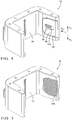
- high permeance structure 18 may be over-molded with an over-molding material 56 which may be an elastomeric polymer, for example, Hytrel®. While the majority of high permeance structure 18 is covered with over-molding material 56, the portion of face 24a of leg 24 which mates with lower end surface 48 of core 16 is not covered with over-molding material 56 because intimate contact between face 24a of leg 24 which mates with lower end surface 48 of core 16 is needed. Over-molding material 56 may reduce the stress concentrations in encapsulant 30 at upper end surface 46 of core 16. It should be noted that for clarity, high permeance structure 18 is shown in Fig. 3 without over-molding material 56.
- Over-molding material 56 may be formed with lip 58 to aid in holding core 16 in place during assembly.
- Lip 58 may be shaped to be substantially similar to a portion of the perimeter of upper end surface 46 of core 16 and defines recessed region 60 within which upper end surface 46 of core 16 is received.
- lip 58 is arranged to prevent movement of core 16 (not shown in Fig. 4 ) in three directions during manufacture as indicated by arrows A 1 , A 2 , A 3 . As shown, the three directions indicated by arrows A 1 , A 2 , A 3 lie in a plane defined by recessed region 60.
- Recessed region 60 may include air gap setting window 62 therethrough which exposes a portion of face 22a of high permeance structure 18.
- Air gap setting window 62 is formed with a part of the mold (not shown) which is used to form over-molding material 56 on high permeance structure 18. This allows for a precise thickness of over-molding material 56 on face 22a of high permeance structure 18 which is needed for a maintaining air gap 54 at a desired thickness.
- Air gap setting window 62 may preferably be spaced away from lip 58 and may preferably be substantially centered within recessed region 60 so that core 16 may be supported by recessed region 60 around the perimeter of core 16. While lip 58 has been described to be shaped to be substantially similar to a portion of the perimeter of upper end surface 46 of core 16 and defines recessed region 60 within which upper end surface 46 of core 16 is received, it should now be understood that the shape of lip 58 need not be substantially similar to a portion of the perimeter of upper end surface 46 of core 16, but rather may be shaped substantially different, but sized to substantially prevent movement of core 16 in the direction of arrows A 1 , A 2 , A 3 . For example only, while core 16 is substantially oval in cross-sectional shape, lip 58 may be substantially rectangular in shape.
- lip 58 may be modified as indicated by lip 58' shown in Fig. 6 .
- Lip 58' differs from lip 58 in that lip 58' completely surrounds core 16 (not shown in Fig. 6 ) and is shaped to be substantially similar to the entire perimeter of upper end surface 46 of core 16. In this way, lip 58' not only prevents movement in the three directions indicated by arrows A 1 , A 2 , A 3 , but also a fourth direction A 4 which is in the opposite direction as arrow A 3 .
- lip 58' has been described to be shaped to be substantially similar to the entire perimeter of upper end surface 46 of core 16 and defines recessed region 60 within which upper end surface 46 of core 16 is received, it should now be understood that the shape of lip 58' need not be substantially similar to a portion of the perimeter of upper end surface 46 of core 16, but rather may be shaped substantially different, but sized to substantially prevent movement of core 16 in the direction of arrows A 1 , A 2 , A 3 , A 4 .
- core 16 is substantially oval in cross-sectional shape
- lip 58 may be substantially rectangular in shape.
- FIGs. 4, 5 , and 6 there are additional openings through over-molding material 56 that exposes other areas of high permeance structure 18 besides portions of face 22a and face 24a.
- silicon steel lamination 52 m (numbered in Fig. 3 ) is exposed through six circular shaped openings (not numbered) through over-molding material 56.
- silicon steel lamination 52 1 (numbered in Fig. 3 ) is exposed through six circular shaped openings (not numbered) through over-molding material 56.
- Figs. 4, 5 , and 6 also show that several silicon steel laminations 52 (numbered in Fig.
- Over-molding material 56 is applied to high permeance structure 18 by a conventional over-molding process in which high permeance structure 18 is placed in a mold (not shown) and over-molding material 56 in liquid form is injected into the mold, thereby filling the void between the mold and high permeance structure 18.
- the mold that is used includes features that contact high permeance structure 18 to keep high permeance structure precisely positioned in the mold to accurately apply over-molding material 56.
- Over-molding material 56 is allowed to solidify and the mold is removed to reveal high permeance structure 18 that is substantially over-molded with over-molding material 56.
- Fig. 7A is a view in the direction of arrow 7A of Fig. 3 of a portion of core 16 and leg 22 of high permeance structure 18 and Fig. 7B is a radial cross-section view of core 16.
- core 16 is preferably generally oval in overall radial cross-sectional shape. Accordingly, core 16 includes major axis A major and minor axis A minor .
- Major axis A major extends in the direction across the radial cross-section of core 16 defined by each laminated steel plate 50 1 -50 n while minor axis A minor extends in the direction across the radial cross-section of core 16 which is perpendicular to major axis A major .
- Major axis A major also extends in the same direction as the width W (parallel to the direction in which silicon steel laminations 52 are stacked) of high permeance structure 18 which is the sum of the thicknesses of silicon steel laminations 52 1 -52 m .
- the generally oval shape of core 16 is accomplished by varying the width of each laminated steel plate 50 1 -50 n in the direction of minor axis A minor . As shown in Fig.
- a core middle section 64 may have laminated steel plates of common width in the direction of minor axis A minor while a first core end section 66 and a second core end section 68 have laminated steel plates of decreasing width from core middle section 64 to laminated steel plates 50 1 and 50 n respectively.
- This arrangement produces a generally oval or racetrack shape with straight sides 70a, 70b that are parallel to each other and connected at each end by arcuate ends 72a, 72b that oppose each other.
- Fig. 8A is a view similar to that of Fig 7A except that core 16 is replaced with core 16' which is generally circular in radial cross-sectional shape and Fig. 8B is a radial cross-section view of core 16'.
- Core 16' includes laminated steel plates 50' 1 , 50' 2 , 50' x .
- the dimension of core 16' in the same direction as width W of high permeance structure 18 must be decreased in comparison to core 16. This may be most readily visible in Fig. 3 which includes core 16. If the dimension of core 16 along major axis A major is held constant and the dimension of core 16 along minor axis A minor is adjusted to produce substantially circular core 16' as shown in Fig. 8B , the core would extend beyond leg 22 and leg 24 of high permeance structure 18, thereby increasing the overall packaging size of ignition coil 10. Referring now to Figs.
- the overall packaging size of the ignition coil is maintained by having the dimension of core 16' along axis A' minor the same as the dimension of core 16 along axis A minor .
- the dimension of core 16' along axis A'major is decreased (in comparison to the dimension of core 16 along axis A major ) to be the same dimension as the dimension of core 16' along axis A' minor , thereby making core 16' substantially circular in cross-section.
- FIG. 7A and 8A the benefit of the radial cross-section shape of core 16 over core 16' can be appreciated by a comparison of flux lines 74 shown in Fig. 7A and flux lines 74' shown in Fig. 8A .
- flux lines 74' that are near laminated steel plates 50' 1 , 50' x and silicon steel laminations 52 1 , 52 m are approaching being perpendicular to laminated steel plates 50' and silicon steel laminations 52 which increases flux loss due to an increase of eddy currents.
- Fig. 8A flux lines 74' that are near laminated steel plates 50' 1 , 50' x and silicon steel laminations 52 1 , 52 m are approaching being perpendicular to laminated steel plates 50' and silicon steel laminations 52 which increases flux loss due to an increase of eddy currents.
- Fig. 8A flux lines 74' that are near laminated steel plates 50' 1 , 50' x and silicon steel laminations 52 1 , 52 m are approaching being perpen
- flux lines 74 that are near laminated steel plates 50' 1 , 50' n and silicon steel laminations 52 1 , 52 m do not approach being perpendicular to laminated steel plates 50 and silicon steel laminations 52 to the same extent as in Fig. 8A which uses substantially circular core 16'.
- Flux lines 70 being more close to paralleling laminated steel plates 50 and silicon steel laminations 52 near laminated steel plates 50'1, 50'n and silicon steel laminations 52 1 , 52 m reduces flux loss due to a decrease in eddy currents.
- core 16 has been described as being generally oval in overall shape in radial cross-section, it should now be understood that core 16 may take the form of other non-circular shapes in radial cross-section.
- core 16 may be rectangular, hexagonal, or octagonal.
- the dimension of core 16 along axis A major is greater than the dimension of core 16 along axis A minor .
Description
- The present invention relates to an ignition coil for developing a spark firing voltage that is applied to one or more spark plugs of an internal combustion engine.
-
WO2011/002829 andUS2008/266040 disclose ignition coil relevant to the present invention. Ignition coils are known for use in connection with an internal combustion engine such as an automobile engine. Ignition coils typically include a primary winding, a secondary winding, and a magnetic circuit. The magnetic circuit conventionally may include a central core extending along an axis and located radially inward of the primary and secondary windings and magnetically coupled thereto. In one arrangement, a C-shaped high permeance structure is included to provide a high permeance magnetic return path. The high permeance structure may include a base section from which a pair of legs extends. The central core is placed between the legs such that the axis of the core extends through the legs of the high permeance structure and such that at least one end of the core is spaced apart from the leg to which it is adjacent to define an air gap. The primary winding, secondary winding, core and high permeance structure are contained in a case formed of an electrical insulating material. The case is filled with an insulating resin or the like for insulating purposes. In this configuration, insulating resin that fills the air gap may be subject to stress from the core during operation of the ignition coil. This stress may lead to undesired performance of the ignition coil. - What is needed is an ignition coil which minimizes or eliminates one or more of the shortcomings as set forth above.
- The invention consists on an ignition coil for an internal combustion engine includes a magnetically-permeable core extending along a core longitudinal axis, the core having a pair of end surfaces on axially-opposite ends thereof. The ignition coil also includes a primary winding disposed outward of the core, a secondary winding disposed outward of the primary winding, and a structure comprising magnetically-permeable steel laminations having a base and a pair of legs, the structure defining a magnetic return path. The core is disposed between the pair of legs such that the core longitudinal axis extends through the legs and the end surfaces face toward the legs and at least one of the end surfaces of the core is spaced apart from a respective one of the legs to define an air gap. The core has a radial cross-section that is non-circular in shape and is substantially oval in radial cross-section. The substantially oval shape in radial cross-section includes a pair of straight sides that are parallel to each other and connected at each end by arcuate ends that oppose each other. The structure is over-molded with an over-molding material such that the over-molding material fills at least a portion of the air gap. The over-molding material is an elastomeric polymer. The over-molding material defines a recessed region within at least one of the end surfaces of the core is received. The recessed region, which is located on one of the legs, includes an air gap setting window through said over-molding material to expose said structure. The recessed region is defined by a lip. The lip follows a portion of the perimeter of at least one of the end surfaces of the core. The lip substantially prevents movement in three directions in a plane defined by the region. A first direction of the three directions is parallel to a width of the structure, the width being defined by the sum of the steel laminations. A second direction of the three directions is opposite to the first direction; and a third direction of the three directions is perpendicular to the first and second directions and in a direction toward said base. The lip prevents movement of the core in a fourth direction in the plane, wherein the fourth direction is opposite to the third direction. The sum of the steel laminations defines a width of the structure and wherein the core includes:
- a major axis perpendicular to the core longitudinal axis and parallel to the width of the structure; a minor axis perpendicular to the core longitudinal axis and perpendicular to the major axis. The dimension of the core along the major axis is greater than a dimension of the core along said minor axis.
- The at least one of the legs includes a face that faces toward the core and is tapered from a thicker section that is proximal to the base to a thinner section that is distal from the base. Each of the legs includes a face that is that faces toward the core and is tapered from a thicker section that is proximal to the base to a thinner section that is distal from the base. The face of one of the legs is free of the over-molding material such that the core is in intimate contact with the face. The face of the other legs includes the over-molding material that fills at least the portion of the air gap.
- This invention will be further described with reference to the accompanying drawings in which:
-
Fig. 1 is a simplified cross-section view of an ignition coil in accordance with the present invention; -
Fig. 2 is a radial cross-section view of a core of the ignition coil ofFig. 1 ; -
Fig. 3 is and isometric view of a high permeance structure and core of the ignition coil ofFig. 1 ; -
Figs. 4 and 5 are isometric views of the high permeance structure ofFig. 3 with an over-molding material over-molded thereto; -
Fig. 6 is an isometric view of a second embodiment of a high permeance structure with an over-molding material; -
Fig. 7A is an elevation view of a portion of the high permeance structure and core ofFig. 3 in the direction of arrow 7A; -
Fig. 7B is a radial cross-section view of the core ofFig. 7A ; -
Fig. 8A is a cross-section view similar to the cross-section view ofFig. 7A except with a core having a circular cross-sectional shape; and -
Fig. 8B is a cross-section view of the core ofFig. 8A . - Referring now to the drawings wherein like reference numerals are used to identify identical components in the various views,
Figure 1 is a simplified cross-section view of anignition coil 10.Ignition coil 10 may be controlled by acontrol unit 12 or the like.Ignition coil 10 is configured for connection to a spark plug 14 that is in threaded engagement with a spark plug opening (not shown) in an internal combustion engine (also not shown).Ignition coil 10 is configured to output a high-voltage (HV) output to spark plug 14, as shown. Generally, overall spark timing (dwell control) and the like is provided bycontrol unit 12. Oneignition coil 10 may be provided per spark plug 14. -
Ignition coil 10 may include a magnetically-permeable core 16, a magnetically-permeable structure 18 configured to provide a high permeance magnetic return path which has abase section 20 and a pair oflegs primary winding spool 26, aprimary winding 28, a quantity ofencapsulant 30 such as an epoxy potting material, asecondary winding spool 32, asecondary winding 34, acase 36, a low-voltage (LV)connector body 38 having primary terminals 40 (only oneprimary terminal 40 is visible in the figures due to being hidden behindprimary terminal 40 shown inFig. 1 ), and a high-voltage (HV)tower 42 having a high-voltage (HV) terminal 44. - Now referring to
Figs. 1 and2 ,core 16 extends along a core longitudinal axis A and is generally oval in overall shape in radial cross-section as shown inFig. 2 , which is a radial cross-section view ofcore 16.Core 16 includes anupper end surface 46 at one axial end and alower end surface 48 at the other axial end which is opposite ofupper end surface 46.Core 16 may compriselaminated steel plates Fig. 2 . Alternatively but not shown,core 16 may comprise compression molded insulated iron particles rather thanlaminated steel plates 50.Core 16 will be described in more detail later. - Now referring again to
Fig. 1 , primary windingspool 26 is configured to receive and retain primary winding 28. Primary windingspool 26 is disposed adjacent to and radially outward ofcore 16 and is preferably in coaxial relationship therewith. Primary windingspool 26 may comprise any one of a number of conventional spool configurations known to those of ordinary skill in the art. In the illustrated embodiment, primary windingspool 26 is configured to receive one continuous primary winding. Primary windingspool 26 may be formed generally of electrical insulating material having properties suitable for use in a relatively high temperature environment. For example, primary windingspool 26 may comprise plastic material such as PPO/PS (e.g., NORYL® available from General Electric) or polybutylene terephthalate (PBT) thermoplastic polyester. It should be understood that there are a variety of alternative materials that may be used for primary windingspool 26. - Primary winding 28, as described above, is wound onto primary winding
spool 26. Primary winding 28 includes first and second ends that are connected to theprimary terminals 40 inLV connector body 38. Primary winding 28 is configured to carry a primary current IP for chargingignition coil 10 upon control ofcontrol unit 12. Primary winding 28 may comprise copper, insulated magnet wire, with a size typically between about 20-23 AWG. - Secondary winding
spool 32 is configured to receive and retain secondary winding 34. Secondary windingspool 32 is disposed adjacent to and radially outward of the centralcomponents comprising core 16, primary windingspool 26 and primary winding 28 and, preferably, is in coaxial relationship therewith. Secondary windingspool 32 may comprise any one of a number of conventional spool configurations known to those of ordinary skill in the art. In the illustrated embodiment, secondary windingspool 32 is configured for use with a segmented winding strategy where a plurality of axially spaced ribs forms a plurality of channels therebetween for accepting the windings. However, it should be understood that other known configurations may be employed, such as, for example only, a configuration adapted to receive one continuous secondary winding (e.g., progressive winding). Secondary windingspool 32 may be formed generally of electrical insulating material having properties suitable for use in a relatively high temperature environment. For example, secondary windingspool 32 may comprise plastic material such as PPO/PS (e.g., NORYL available from General Electric) or polybutylene terephthalate (PBT) thermoplastic polyester. It should be understood that there are a variety of alternative materials that may be used for secondary windingspool 32. -
Encapsulant 30 may be suitable for providing electrical insulation withinignition coil 10. In a preferred embodiment,encapsulant 30 may comprise an epoxy potting material.Sufficient encapsulant 30 is introduced inignition coil 10, in the illustrated embodiment, to substantially fill the interior ofcase 36.Encapsulant 30 also provides protection from environmental factors which may be encountered during the service life ofignition coil 10. There are a number of encapsulant materials known in the art. - Secondary winding 34 includes a low-voltage (LV) end and a high-voltage (HV) end. The LV end may be connected to ground by way of a ground connection through
LV connector body 38 or in other ways known in the art. The HV end is connected to HV terminal 44, a metal post or the like that may be formed in secondary windingspool 32 or elsewhere. Secondary winding 34 may be implemented using conventional approaches and material (e.g. copper, insulate magnet wire) known to those of ordinary skill in the art. - Referring now to
Figs. 1 and3 ,high permeance structure 18 is configured to provide a high permeance magnetic return path for the magnetic flux produced incore 16 during operation ofignition coil 10.High permeance structure 18 may be formed, for example, from a lamination stack that includes a plurality ofsilicon steel laminations high permeance structure 18 includesbase section 20 and a pair oflegs Leg 22 may extend substantially perpendicular from an end ofbase section 20 that is proximal toupper end surface 46 ofcore 16 whileleg 24 may extend substantially perpendicular from an end ofbase section 20 that is proximal tolower end surface 48 ofcore 16. As shown inFigs. 1 and3 , aface 22a ofleg 22 that faces the concave portion (faces core 16) ofhigh permeance structure 18 may be tapered from a thicker section that is proximal tobase section 20 to a thinner section that is distal frombase section 20.Upper end surface 46 ofcore 16 is tapered to be substantially parallel to face 22a ofleg 22. Similarly, aface 24a ofleg 24 that faces the concave portion ofhigh permeance structure 18 may be tapered from a thicker section that is proximal tobase section 20 to a thinner section that is distal frombase section 20.Lower end surface 48 ofcore 16 is tapered to be substantially parallel to face 24a ofleg 24. Alternatively, but not shown, only one offace 22a andface 24a may be tapered while the other offace 22a andface 24a may be substantially perpendicular tobase section 20. Also alternatively, but not shown,face 22a andface 24a may both be substantially perpendicular tobase section 20. - In the illustrated embodiment,
lower end surface 48 ofcore 16 mates withface 24a ofleg 24 ofhigh permeance structure 18.Upper end surface 46 ofcore 16, on the other hand, is spaced apart from theleg 24 by a predetermined distance defining anair gap 54.Core 16, in combination withhigh permeance structure 18, inview air gap 54, forms a magnetic circuit having a high magnetic permeability. The typical range forair gap 54 is 0.5 mm to 2 mm. To maximize energy stored,air gap 54 should be large enough to keep core 16 from saturating to the normal operating current, or level of ampere-turns (primary current x primary turns). - Now referring to
Figs. 1 ,4, and 5 ,high permeance structure 18 may be over-molded with anover-molding material 56 which may be an elastomeric polymer, for example, Hytrel®. While the majority ofhigh permeance structure 18 is covered withover-molding material 56, the portion offace 24a ofleg 24 which mates withlower end surface 48 ofcore 16 is not covered withover-molding material 56 because intimate contact betweenface 24a ofleg 24 which mates withlower end surface 48 ofcore 16 is needed.Over-molding material 56 may reduce the stress concentrations inencapsulant 30 atupper end surface 46 ofcore 16. It should be noted that for clarity,high permeance structure 18 is shown inFig. 3 withoutover-molding material 56. -
Over-molding material 56 may be formed withlip 58 to aid in holdingcore 16 in place during assembly.Lip 58 may be shaped to be substantially similar to a portion of the perimeter ofupper end surface 46 ofcore 16 and defines recessedregion 60 within whichupper end surface 46 ofcore 16 is received. As shown inFig. 4 ,lip 58 is arranged to prevent movement of core 16 (not shown inFig. 4 ) in three directions during manufacture as indicated by arrows A1, A2, A3. As shown, the three directions indicated by arrows A1, A2, A3 lie in a plane defined by recessedregion 60. Arrows A1, A2 are in opposing directions to each other and parallel to the direction in whichsilicon steel laminations 52 are stacked while arrow A3 points towardbase section 20 and is in a direction perpendicular to arrows A1, A2. Recessedregion 60 may include airgap setting window 62 therethrough which exposes a portion offace 22a ofhigh permeance structure 18. Airgap setting window 62 is formed with a part of the mold (not shown) which is used to formover-molding material 56 onhigh permeance structure 18. This allows for a precise thickness ofover-molding material 56 onface 22a ofhigh permeance structure 18 which is needed for a maintainingair gap 54 at a desired thickness. Airgap setting window 62 may preferably be spaced away fromlip 58 and may preferably be substantially centered within recessedregion 60 so thatcore 16 may be supported by recessedregion 60 around the perimeter ofcore 16. Whilelip 58 has been described to be shaped to be substantially similar to a portion of the perimeter ofupper end surface 46 ofcore 16 and defines recessedregion 60 within whichupper end surface 46 ofcore 16 is received, it should now be understood that the shape oflip 58 need not be substantially similar to a portion of the perimeter ofupper end surface 46 ofcore 16, but rather may be shaped substantially different, but sized to substantially prevent movement ofcore 16 in the direction of arrows A1, A2, A3. For example only, whilecore 16 is substantially oval in cross-sectional shape,lip 58 may be substantially rectangular in shape. - Alternatively,
lip 58 may be modified as indicated by lip 58' shown inFig. 6 . Lip 58' differs fromlip 58 in that lip 58' completely surrounds core 16 (not shown inFig. 6 ) and is shaped to be substantially similar to the entire perimeter ofupper end surface 46 ofcore 16. In this way, lip 58' not only prevents movement in the three directions indicated by arrows A1, A2, A3, but also a fourth direction A4 which is in the opposite direction as arrow A3. While lip 58' has been described to be shaped to be substantially similar to the entire perimeter ofupper end surface 46 ofcore 16 and defines recessedregion 60 within whichupper end surface 46 ofcore 16 is received, it should now be understood that the shape of lip 58' need not be substantially similar to a portion of the perimeter ofupper end surface 46 ofcore 16, but rather may be shaped substantially different, but sized to substantially prevent movement ofcore 16 in the direction of arrows A1, A2, A3, A4. For example only, whilecore 16 is substantially oval in cross-sectional shape,lip 58 may be substantially rectangular in shape. - As can be seen in
Figs. 4, 5 , and6 ; there are additional openings throughover-molding material 56 that exposes other areas ofhigh permeance structure 18 besides portions offace 22a andface 24a. As oriented inFigs. 4 and6 , silicon steel lamination 52m (numbered inFig. 3 ) is exposed through six circular shaped openings (not numbered) throughover-molding material 56. Similarly, as oriented inFig. 5 , silicon steel lamination 521 (numbered inFig. 3 ) is exposed through six circular shaped openings (not numbered) throughover-molding material 56.Figs. 4, 5 , and6 also show that several silicon steel laminations 52 (numbered inFig. 3 ) are exposed atbase section 20 through an elongated opening (not numbered) throughover-molding material 56. It should be noted that the circular openings exposing portions ofsilicon steel lamination 521 andsilicon steel lamination 52m and the elongated opening exposing severalsilicon steel laminations 52 atbase section 20 do not serve a function in completedignition coil 10, but are the result of the over-molding process used to applyover-molding material 56 tohigh permeance structure 18.Over-molding material 56 is applied tohigh permeance structure 18 by a conventional over-molding process in whichhigh permeance structure 18 is placed in a mold (not shown) andover-molding material 56 in liquid form is injected into the mold, thereby filling the void between the mold andhigh permeance structure 18. In this case, the mold that is used includes features that contacthigh permeance structure 18 to keep high permeance structure precisely positioned in the mold to accurately applyover-molding material 56.Over-molding material 56 is allowed to solidify and the mold is removed to revealhigh permeance structure 18 that is substantially over-molded withover-molding material 56. - Reference will now be made to
Figs. 3 ,7A, and 7B whereFig. 7A is a view in the direction of arrow 7A ofFig. 3 of a portion ofcore 16 andleg 22 ofhigh permeance structure 18 andFig. 7B is a radial cross-section view ofcore 16. As described previously,core 16 is preferably generally oval in overall radial cross-sectional shape. Accordingly,core 16 includes major axis Amajor and minor axis Aminor. Major axis Amajor extends in the direction across the radial cross-section ofcore 16 defined by each laminated steel plate 501-50n while minor axis Aminor extends in the direction across the radial cross-section ofcore 16 which is perpendicular to major axis Amajor. Major axis Amajor also extends in the same direction as the width W (parallel to the direction in whichsilicon steel laminations 52 are stacked) ofhigh permeance structure 18 which is the sum of the thicknesses of silicon steel laminations 521-52m. The generally oval shape ofcore 16 is accomplished by varying the width of each laminated steel plate 501-50n in the direction of minor axis Aminor. As shown inFig. 7B , a coremiddle section 64 may have laminated steel plates of common width in the direction of minor axis Aminor while a firstcore end section 66 and a secondcore end section 68 have laminated steel plates of decreasing width from coremiddle section 64 tolaminated steel plates straight sides 70a, 70b that are parallel to each other and connected at each end byarcuate ends 72a, 72b that oppose each other. - Reference will now be made to
Figs. 8A and 8B whereFig. 8A is a view similar to that ofFig 7A except thatcore 16 is replaced with core 16' which is generally circular in radial cross-sectional shape andFig. 8B is a radial cross-section view of core 16'. Core 16' includes laminated steel plates 50'1, 50'2, 50'x. - In order to maintain the same overall packaging size of the ignition coil when using generally circular core 16', the dimension of core 16' in the same direction as width W of
high permeance structure 18 must be decreased in comparison tocore 16. This may be most readily visible inFig. 3 which includescore 16. If the dimension ofcore 16 along major axis Amajor is held constant and the dimension ofcore 16 along minor axis Aminor is adjusted to produce substantially circular core 16' as shown inFig. 8B , the core would extend beyondleg 22 andleg 24 ofhigh permeance structure 18, thereby increasing the overall packaging size ofignition coil 10. Referring now toFigs. 7B and8B , the overall packaging size of the ignition coil is maintained by having the dimension of core 16' along axis A'minor the same as the dimension ofcore 16 along axis Aminor. However, the dimension of core 16' along axis A'major is decreased (in comparison to the dimension ofcore 16 along axis Amajor) to be the same dimension as the dimension of core 16' along axis A'minor, thereby making core 16' substantially circular in cross-section. - Now referring to
Figs. 7A and8A , the benefit of the radial cross-section shape ofcore 16 over core 16' can be appreciated by a comparison offlux lines 74 shown inFig. 7A and flux lines 74' shown inFig. 8A . As can be seen inFig. 8A , flux lines 74' that are near laminated steel plates 50'1, 50'x andsilicon steel laminations silicon steel laminations 52 which increases flux loss due to an increase of eddy currents. Also as can be seen inFig. 7A ,flux lines 74 that are near laminated steel plates 50'1, 50'n andsilicon steel laminations laminated steel plates 50 andsilicon steel laminations 52 to the same extent as inFig. 8A which uses substantially circular core 16'. Flux lines 70 being more close to parallelinglaminated steel plates 50 andsilicon steel laminations 52 near laminated steel plates 50'1, 50'n andsilicon steel laminations - While
core 16 has been described as being generally oval in overall shape in radial cross-section, it should now be understood thatcore 16 may take the form of other non-circular shapes in radial cross-section. For example only,core 16 may be rectangular, hexagonal, or octagonal. Preferably, regardless of shape, the dimension ofcore 16 along axis Amajor is greater than the dimension ofcore 16 along axis Aminor. - While this invention has been described in terms of preferred embodiments thereof, it is not intended to be so limited, but rather only to the extent set forth in the claims that follow.
Claims (13)
- An ignition coil (10) for an internal combustion engine, comprising:a magnetically-permeable core (16) extending along a core longitudinal axis (A), said core (16) having a pair of end surfaces (46, 48) on axially-opposite ends thereof;a primary winding (28) disposed outward of said core (16);a secondary winding (34) disposed outward of said primary winding (28); anda structure (18) comprising magnetically-permeable steel laminations (54) having a base (20) and a pair of legs (22, 24), said structure (18) defining a magnetic return path;wherein said core (16) is disposed between said pair of legs (22, 24) whereby said core longitudinal axis (A) extends through said legs (22, 24) and said end surfaces (46, 48) face toward said legs (22, 24) and at least one of said end surfaces (46) of said core (16) is spaced apart from a respective one of said legs (22) to define an air gap (54), andwherein said structure (18) is over-molded with an over-molding material (56) whereby said over-molding material (56) fills at least a portion of said air gap (54) andwherein said over-molding material (56) is an elastomeric polymer andwherein said over-molding material (56) defines a recessed region (60) within which said at least one of said end surfaces (46) of said core (16) is received andwherein said recessed region (60) is defined by a lip (58).
- An ignition coil (10) as set in any of the previous claims wherein said core (16) has a radial cross-section that is non-circular in shape.
- An ignition coil (10) as set in any of the previous claims wherein said core (16) is substantially oval shape in radial cross-section.
- An ignition coil (10) as set in any of previous claims wherein the sum of said steel laminations (54) defines a width (W) of said structure (18) and wherein said core (16) includes:a major axis (Amajor) perpendicular to said core longitudinal axis (A) and parallel to said width (W) of said structure (18); anda minor axis (Aminor) perpendicular to said core longitudinal axis (A) and perpendicular to said major axis (Amajor);wherein a dimension of said core (16) along said major axis (Amajor) is greater than a dimension of said core (16) along said minor axis (Aminor).
- An ignition coil (10) as set in any of the previous claims wherein at least one of said legs (22, 24) includes a face (22a, 24a) that faces toward said core (16) and is tapered from a thicker section that is proximal to said base (20) to a thinner section that is distal from said base (20).
- An ignition coil (10) as set in any of preceding claims taken in combination with claim 1 wherein said recessed region (60) includes an air gap setting window (62) through said over-molding material (56) to expose said structure (18).
- An ignition coil (10) as set in any of preceding claims taken in combination with claim 1 wherein said recessed region (60) is located on one of said legs (22).
- An ignition coil (10) as in any one of the preceding claims wherein said lip (58) follows a portion of the perimeter of said at least one of said end surfaces (46) of said core (16).
- An ignition coil (10) as in claim 8 wherein said lip (58) substantially prevents movement in three directions (A1, A2, A3) in a plane defined by said recessed region (60);
wherein a first direction (A1) of said three directions (A1, A2, A3) is parallel to a width (W) of said structure (18), said width (W) being defined by the sum of said steel laminations;
wherein a second direction (A2) of said three directions (A1, A2, A3) is opposite to said first direction (A1); and
wherein a third direction (A3) of said three directions (A1, A2, A3) is perpendicular to said first and second directions (A1, A2) and in a direction toward said base (20). - An ignition coil (10) as in claim 9 wherein said lip (58) prevents movement of said core (16) in a fourth direction (A4) in said plane, wherein said fourth (A4) direction is opposite to said third direction (A3).
- An ignition coil (10) as set in any of preceding claims taken in combination with claim 6 wherein said face (22a) of one of said legs (24) is free of said over-molding material (56) such that said core (16) is in intimate contact with said face (22a).
- An ignition coil (10) as in claim 11 where said face (22a) of the other of said legs (22) includes said over-molding material (56) that fills at least said portion of said air gap (54).
- An ignition coil (10) as set in any of preceding claims taken in combination with claim 3 wherein said substantially oval shape in radial cross-section includes a pair of straight sides (70a, 70b) that are parallel to each other and connected at each end by arcuate ends (72a, 72b) that oppose each other.
Applications Claiming Priority (1)
| Application Number | Priority Date | Filing Date | Title |
|---|---|---|---|
| US13/460,968 US8991371B2 (en) | 2012-05-01 | 2012-05-01 | Ignition coil |
Publications (4)
| Publication Number | Publication Date |
|---|---|
| EP2660833A2 EP2660833A2 (en) | 2013-11-06 |
| EP2660833A3 EP2660833A3 (en) | 2018-01-24 |
| EP2660833B1 true EP2660833B1 (en) | 2019-03-27 |
| EP2660833B8 EP2660833B8 (en) | 2019-05-22 |
Family
ID=48446046
Family Applications (1)
| Application Number | Title | Priority Date | Filing Date |
|---|---|---|---|
| EP13165719.9A Active EP2660833B8 (en) | 2012-05-01 | 2013-04-29 | Ignition coil |
Country Status (2)
| Country | Link |
|---|---|
| US (1) | US8991371B2 (en) |
| EP (1) | EP2660833B8 (en) |
Families Citing this family (6)
| Publication number | Priority date | Publication date | Assignee | Title |
|---|---|---|---|---|
| US9796165B2 (en) * | 2013-12-18 | 2017-10-24 | Delphi Technologies, Inc. | Ignition coil and method of assembly |
| US9812248B2 (en) | 2014-06-16 | 2017-11-07 | Delphi Technologies, Inc. | Ignition coil |
| JP6488568B2 (en) * | 2014-06-27 | 2019-03-27 | 株式会社デンソー | Ignition coil for internal combustion engines |
| JP6729125B2 (en) * | 2016-07-21 | 2020-07-22 | 株式会社デンソー | Ignition coil for internal combustion engine and method of manufacturing the same |
| JP2018190943A (en) * | 2017-05-12 | 2018-11-29 | ウォルブロ リミテッド ライアビリティ カンパニー | Ignition device |
| DE102018130492B4 (en) * | 2018-11-30 | 2023-02-09 | Borgwarner Ludwigsburg Gmbh | ignition coil |
Family Cites Families (9)
| Publication number | Priority date | Publication date | Assignee | Title |
|---|---|---|---|---|
| JP2669021B2 (en) * | 1988-12-27 | 1997-10-27 | 株式会社デンソー | Ignition coil for internal combustion engine |
| JP3900149B2 (en) * | 2003-12-17 | 2007-04-04 | 三菱電機株式会社 | Ignition coil |
| JP3922251B2 (en) * | 2003-12-17 | 2007-05-30 | 三菱電機株式会社 | Ignition coil |
| US7276998B2 (en) * | 2004-11-10 | 2007-10-02 | Enpirion, Inc. | Encapsulated package for a magnetic device |
| DE102005029001A1 (en) | 2005-02-11 | 2006-08-24 | Patent-Treuhand-Gesellschaft für elektrische Glühlampen mbH | Lamp base for a high-pressure discharge lamp and high-pressure discharge lamp |
| DE102006045356A1 (en) * | 2006-09-26 | 2008-04-03 | Robert Bosch Gmbh | Ignition coil, in particular for an internal combustion engine of a motor vehicle |
| US7777604B2 (en) * | 2007-04-27 | 2010-08-17 | Toyo Denso Kabushiki Kaisha | Ignition coil |
| US7882828B2 (en) | 2008-12-01 | 2011-02-08 | Delphi Technologies, Inc. | Ignition apparatus with cylindrical core and laminated return path |
| US8360039B2 (en) * | 2009-07-02 | 2013-01-29 | Delphi Technologies, Inc. | Ignition coil |
-
2012
- 2012-05-01 US US13/460,968 patent/US8991371B2/en active Active
-
2013
- 2013-04-29 EP EP13165719.9A patent/EP2660833B8/en active Active
Non-Patent Citations (1)
| Title |
|---|
| None * |
Also Published As
| Publication number | Publication date |
|---|---|
| US8991371B2 (en) | 2015-03-31 |
| EP2660833B8 (en) | 2019-05-22 |
| EP2660833A3 (en) | 2018-01-24 |
| US20130291844A1 (en) | 2013-11-07 |
| EP2660833A2 (en) | 2013-11-06 |
Similar Documents
| Publication | Publication Date | Title |
|---|---|---|
| EP2660833B1 (en) | Ignition coil | |
| US5349320A (en) | Ignition coil for internal combustion engines | |
| US9117585B2 (en) | Ignition coil | |
| US10207485B2 (en) | Ignition coil and method of assembly | |
| US20130104863A1 (en) | Ignition coil assembly and method | |
| US7882828B2 (en) | Ignition apparatus with cylindrical core and laminated return path | |
| US20190214177A1 (en) | Ignition coil | |
| US8360039B2 (en) | Ignition coil | |
| JPH07238881A (en) | Ignition coil | |
| US7626481B2 (en) | Ignition coil | |
| EP3155625B1 (en) | Ignition coil | |
| JP5695363B2 (en) | Ignition device for internal combustion engine | |
| JP5212329B2 (en) | Ignition coil manufacturing method | |
| KR101416651B1 (en) | Ignition coil | |
| JPH11340066A (en) | Ignition coil for internal combustion engine | |
| JP3055934U (en) | Ignition coil for internal combustion engine | |
| JP2011134876A (en) | Ignition coil for internal combustion engine | |
| JP2008277461A (en) | Ignition coil | |
| JP2009170783A (en) | Ignition coil, and manufacturing method thereof | |
| JP2007053188A (en) | Ignition coil for internal combustion engine | |
| JPH09219330A (en) | Ignition coil for internal combustion engine | |
| JP2008277533A (en) | Ignition coil | |
| JP2004311616A (en) | Primary coil of ignition coil for internal-combustion engine | |
| JPH1074650A (en) | Engine spark coil device | |
| JP2004186578A (en) | Ignition coil |
Legal Events
| Date | Code | Title | Description |
|---|---|---|---|
| PUAI | Public reference made under article 153(3) epc to a published international application that has entered the european phase |
Free format text: ORIGINAL CODE: 0009012 |
|
| AK | Designated contracting states |
Kind code of ref document: A2 Designated state(s): AL AT BE BG CH CY CZ DE DK EE ES FI FR GB GR HR HU IE IS IT LI LT LU LV MC MK MT NL NO PL PT RO RS SE SI SK SM TR |
|
| AX | Request for extension of the european patent |
Extension state: BA ME |
|
| PUAL | Search report despatched |
Free format text: ORIGINAL CODE: 0009013 |
|
| AK | Designated contracting states |
Kind code of ref document: A3 Designated state(s): AL AT BE BG CH CY CZ DE DK EE ES FI FR GB GR HR HU IE IS IT LI LT LU LV MC MK MT NL NO PL PT RO RS SE SI SK SM TR |
|
| AX | Request for extension of the european patent |
Extension state: BA ME |
|
| RIC1 | Information provided on ipc code assigned before grant |
Ipc: H01F 27/02 20060101ALI20171220BHEP Ipc: H01F 38/12 20060101AFI20171220BHEP |
|
| STAA | Information on the status of an ep patent application or granted ep patent |
Free format text: STATUS: REQUEST FOR EXAMINATION WAS MADE |
|
| 17P | Request for examination filed |
Effective date: 20180724 |
|
| RBV | Designated contracting states (corrected) |
Designated state(s): AL AT BE BG CH CY CZ DE DK EE ES FI FR GB GR HR HU IE IS IT LI LT LU LV MC MK MT NL NO PL PT RO RS SE SI SK SM TR |
|
| GRAP | Despatch of communication of intention to grant a patent |
Free format text: ORIGINAL CODE: EPIDOSNIGR1 |
|
| STAA | Information on the status of an ep patent application or granted ep patent |
Free format text: STATUS: GRANT OF PATENT IS INTENDED |
|
| RIC1 | Information provided on ipc code assigned before grant |
Ipc: H01F 38/12 20060101AFI20180927BHEP Ipc: H01F 27/02 20060101ALI20180927BHEP |
|
| INTG | Intention to grant announced |
Effective date: 20181017 |
|
| GRAS | Grant fee paid |
Free format text: ORIGINAL CODE: EPIDOSNIGR3 |
|
| GRAA | (expected) grant |
Free format text: ORIGINAL CODE: 0009210 |
|
| STAA | Information on the status of an ep patent application or granted ep patent |
Free format text: STATUS: THE PATENT HAS BEEN GRANTED |
|
| GRAT | Correction requested after decision to grant or after decision to maintain patent in amended form |
Free format text: ORIGINAL CODE: EPIDOSNCDEC |
|
| AK | Designated contracting states |
Kind code of ref document: B1 Designated state(s): AL AT BE BG CH CY CZ DE DK EE ES FI FR GB GR HR HU IE IS IT LI LT LU LV MC MK MT NL NO PL PT RO RS SE SI SK SM TR |
|
| REG | Reference to a national code |
Ref country code: GB Ref legal event code: FG4D |
|
| REG | Reference to a national code |
Ref country code: CH Ref legal event code: EP |
|
| RAP2 | Party data changed (patent owner data changed or rights of a patent transferred) |
Owner name: DELPHI TECHNOLOGIES IP LIMITED |
|
| REG | Reference to a national code |
Ref country code: AT Ref legal event code: REF Ref document number: 1114011 Country of ref document: AT Kind code of ref document: T Effective date: 20190415 |
|
| REG | Reference to a national code |
Ref country code: IE Ref legal event code: FG4D |
|
| REG | Reference to a national code |
Ref country code: DE Ref legal event code: R096 Ref document number: 602013052823 Country of ref document: DE |
|
| REG | Reference to a national code |
Ref country code: CH Ref legal event code: PK Free format text: BERICHTIGUNG B8 |
|
| PG25 | Lapsed in a contracting state [announced via postgrant information from national office to epo] |
Ref country code: FI Free format text: LAPSE BECAUSE OF FAILURE TO SUBMIT A TRANSLATION OF THE DESCRIPTION OR TO PAY THE FEE WITHIN THE PRESCRIBED TIME-LIMIT Effective date: 20190327 Ref country code: NO Free format text: LAPSE BECAUSE OF FAILURE TO SUBMIT A TRANSLATION OF THE DESCRIPTION OR TO PAY THE FEE WITHIN THE PRESCRIBED TIME-LIMIT Effective date: 20190627 Ref country code: SE Free format text: LAPSE BECAUSE OF FAILURE TO SUBMIT A TRANSLATION OF THE DESCRIPTION OR TO PAY THE FEE WITHIN THE PRESCRIBED TIME-LIMIT Effective date: 20190327 Ref country code: LT Free format text: LAPSE BECAUSE OF FAILURE TO SUBMIT A TRANSLATION OF THE DESCRIPTION OR TO PAY THE FEE WITHIN THE PRESCRIBED TIME-LIMIT Effective date: 20190327 |
|
| REG | Reference to a national code |
Ref country code: NL Ref legal event code: MP Effective date: 20190327 |
|
| PG25 | Lapsed in a contracting state [announced via postgrant information from national office to epo] |
Ref country code: LV Free format text: LAPSE BECAUSE OF FAILURE TO SUBMIT A TRANSLATION OF THE DESCRIPTION OR TO PAY THE FEE WITHIN THE PRESCRIBED TIME-LIMIT Effective date: 20190327 Ref country code: HR Free format text: LAPSE BECAUSE OF FAILURE TO SUBMIT A TRANSLATION OF THE DESCRIPTION OR TO PAY THE FEE WITHIN THE PRESCRIBED TIME-LIMIT Effective date: 20190327 Ref country code: NL Free format text: LAPSE BECAUSE OF FAILURE TO SUBMIT A TRANSLATION OF THE DESCRIPTION OR TO PAY THE FEE WITHIN THE PRESCRIBED TIME-LIMIT Effective date: 20190327 Ref country code: BG Free format text: LAPSE BECAUSE OF FAILURE TO SUBMIT A TRANSLATION OF THE DESCRIPTION OR TO PAY THE FEE WITHIN THE PRESCRIBED TIME-LIMIT Effective date: 20190627 Ref country code: GR Free format text: LAPSE BECAUSE OF FAILURE TO SUBMIT A TRANSLATION OF THE DESCRIPTION OR TO PAY THE FEE WITHIN THE PRESCRIBED TIME-LIMIT Effective date: 20190628 Ref country code: RS Free format text: LAPSE BECAUSE OF FAILURE TO SUBMIT A TRANSLATION OF THE DESCRIPTION OR TO PAY THE FEE WITHIN THE PRESCRIBED TIME-LIMIT Effective date: 20190327 |
|
| REG | Reference to a national code |
Ref country code: AT Ref legal event code: MK05 Ref document number: 1114011 Country of ref document: AT Kind code of ref document: T Effective date: 20190327 |
|
| PG25 | Lapsed in a contracting state [announced via postgrant information from national office to epo] |
Ref country code: EE Free format text: LAPSE BECAUSE OF FAILURE TO SUBMIT A TRANSLATION OF THE DESCRIPTION OR TO PAY THE FEE WITHIN THE PRESCRIBED TIME-LIMIT Effective date: 20190327 Ref country code: IT Free format text: LAPSE BECAUSE OF FAILURE TO SUBMIT A TRANSLATION OF THE DESCRIPTION OR TO PAY THE FEE WITHIN THE PRESCRIBED TIME-LIMIT Effective date: 20190327 Ref country code: CZ Free format text: LAPSE BECAUSE OF FAILURE TO SUBMIT A TRANSLATION OF THE DESCRIPTION OR TO PAY THE FEE WITHIN THE PRESCRIBED TIME-LIMIT Effective date: 20190327 Ref country code: SK Free format text: LAPSE BECAUSE OF FAILURE TO SUBMIT A TRANSLATION OF THE DESCRIPTION OR TO PAY THE FEE WITHIN THE PRESCRIBED TIME-LIMIT Effective date: 20190327 Ref country code: RO Free format text: LAPSE BECAUSE OF FAILURE TO SUBMIT A TRANSLATION OF THE DESCRIPTION OR TO PAY THE FEE WITHIN THE PRESCRIBED TIME-LIMIT Effective date: 20190327 Ref country code: AL Free format text: LAPSE BECAUSE OF FAILURE TO SUBMIT A TRANSLATION OF THE DESCRIPTION OR TO PAY THE FEE WITHIN THE PRESCRIBED TIME-LIMIT Effective date: 20190327 Ref country code: PT Free format text: LAPSE BECAUSE OF FAILURE TO SUBMIT A TRANSLATION OF THE DESCRIPTION OR TO PAY THE FEE WITHIN THE PRESCRIBED TIME-LIMIT Effective date: 20190727 Ref country code: ES Free format text: LAPSE BECAUSE OF FAILURE TO SUBMIT A TRANSLATION OF THE DESCRIPTION OR TO PAY THE FEE WITHIN THE PRESCRIBED TIME-LIMIT Effective date: 20190327 |
|
| PG25 | Lapsed in a contracting state [announced via postgrant information from national office to epo] |
Ref country code: SM Free format text: LAPSE BECAUSE OF FAILURE TO SUBMIT A TRANSLATION OF THE DESCRIPTION OR TO PAY THE FEE WITHIN THE PRESCRIBED TIME-LIMIT Effective date: 20190327 Ref country code: PL Free format text: LAPSE BECAUSE OF FAILURE TO SUBMIT A TRANSLATION OF THE DESCRIPTION OR TO PAY THE FEE WITHIN THE PRESCRIBED TIME-LIMIT Effective date: 20190327 |
|
| REG | Reference to a national code |
Ref country code: CH Ref legal event code: PL |
|
| REG | Reference to a national code |
Ref country code: BE Ref legal event code: MM Effective date: 20190430 |
|
| PG25 | Lapsed in a contracting state [announced via postgrant information from national office to epo] |
Ref country code: LU Free format text: LAPSE BECAUSE OF NON-PAYMENT OF DUE FEES Effective date: 20190429 Ref country code: AT Free format text: LAPSE BECAUSE OF FAILURE TO SUBMIT A TRANSLATION OF THE DESCRIPTION OR TO PAY THE FEE WITHIN THE PRESCRIBED TIME-LIMIT Effective date: 20190327 Ref country code: IS Free format text: LAPSE BECAUSE OF FAILURE TO SUBMIT A TRANSLATION OF THE DESCRIPTION OR TO PAY THE FEE WITHIN THE PRESCRIBED TIME-LIMIT Effective date: 20190727 |
|
| REG | Reference to a national code |
Ref country code: DE Ref legal event code: R097 Ref document number: 602013052823 Country of ref document: DE |
|
| PG25 | Lapsed in a contracting state [announced via postgrant information from national office to epo] |
Ref country code: DK Free format text: LAPSE BECAUSE OF FAILURE TO SUBMIT A TRANSLATION OF THE DESCRIPTION OR TO PAY THE FEE WITHIN THE PRESCRIBED TIME-LIMIT Effective date: 20190327 Ref country code: CH Free format text: LAPSE BECAUSE OF NON-PAYMENT OF DUE FEES Effective date: 20190430 Ref country code: LI Free format text: LAPSE BECAUSE OF NON-PAYMENT OF DUE FEES Effective date: 20190430 Ref country code: MC Free format text: LAPSE BECAUSE OF FAILURE TO SUBMIT A TRANSLATION OF THE DESCRIPTION OR TO PAY THE FEE WITHIN THE PRESCRIBED TIME-LIMIT Effective date: 20190327 |
|
| PLBE | No opposition filed within time limit |
Free format text: ORIGINAL CODE: 0009261 |
|
| STAA | Information on the status of an ep patent application or granted ep patent |
Free format text: STATUS: NO OPPOSITION FILED WITHIN TIME LIMIT |
|
| PG25 | Lapsed in a contracting state [announced via postgrant information from national office to epo] |
Ref country code: BE Free format text: LAPSE BECAUSE OF NON-PAYMENT OF DUE FEES Effective date: 20190430 Ref country code: SI Free format text: LAPSE BECAUSE OF FAILURE TO SUBMIT A TRANSLATION OF THE DESCRIPTION OR TO PAY THE FEE WITHIN THE PRESCRIBED TIME-LIMIT Effective date: 20190327 |
|
| 26N | No opposition filed |
Effective date: 20200103 |
|
| PG25 | Lapsed in a contracting state [announced via postgrant information from national office to epo] |
Ref country code: TR Free format text: LAPSE BECAUSE OF FAILURE TO SUBMIT A TRANSLATION OF THE DESCRIPTION OR TO PAY THE FEE WITHIN THE PRESCRIBED TIME-LIMIT Effective date: 20190327 |
|
| PG25 | Lapsed in a contracting state [announced via postgrant information from national office to epo] |
Ref country code: IE Free format text: LAPSE BECAUSE OF NON-PAYMENT OF DUE FEES Effective date: 20190429 |
|
| PG25 | Lapsed in a contracting state [announced via postgrant information from national office to epo] |
Ref country code: CY Free format text: LAPSE BECAUSE OF FAILURE TO SUBMIT A TRANSLATION OF THE DESCRIPTION OR TO PAY THE FEE WITHIN THE PRESCRIBED TIME-LIMIT Effective date: 20190327 |
|
| PG25 | Lapsed in a contracting state [announced via postgrant information from national office to epo] |
Ref country code: MT Free format text: LAPSE BECAUSE OF FAILURE TO SUBMIT A TRANSLATION OF THE DESCRIPTION OR TO PAY THE FEE WITHIN THE PRESCRIBED TIME-LIMIT Effective date: 20190327 Ref country code: HU Free format text: LAPSE BECAUSE OF FAILURE TO SUBMIT A TRANSLATION OF THE DESCRIPTION OR TO PAY THE FEE WITHIN THE PRESCRIBED TIME-LIMIT; INVALID AB INITIO Effective date: 20130429 |
|
| PG25 | Lapsed in a contracting state [announced via postgrant information from national office to epo] |
Ref country code: MK Free format text: LAPSE BECAUSE OF FAILURE TO SUBMIT A TRANSLATION OF THE DESCRIPTION OR TO PAY THE FEE WITHIN THE PRESCRIBED TIME-LIMIT Effective date: 20190327 |
|
| PGFP | Annual fee paid to national office [announced via postgrant information from national office to epo] |
Ref country code: FR Payment date: 20230320 Year of fee payment: 11 |
|
| PGFP | Annual fee paid to national office [announced via postgrant information from national office to epo] |
Ref country code: GB Payment date: 20230315 Year of fee payment: 11 |
|
| P01 | Opt-out of the competence of the unified patent court (upc) registered |
Effective date: 20230327 |
|
| PGFP | Annual fee paid to national office [announced via postgrant information from national office to epo] |
Ref country code: DE Payment date: 20230320 Year of fee payment: 11 |