EP2774847A1 - Removeable rotor blade tip - Google Patents
Removeable rotor blade tip Download PDFInfo
- Publication number
- EP2774847A1 EP2774847A1 EP13165390.9A EP13165390A EP2774847A1 EP 2774847 A1 EP2774847 A1 EP 2774847A1 EP 13165390 A EP13165390 A EP 13165390A EP 2774847 A1 EP2774847 A1 EP 2774847A1
- Authority
- EP
- European Patent Office
- Prior art keywords
- anchor
- connector
- root
- rotor blade
- rotor
- Prior art date
- Legal status (The legal status is an assumption and is not a legal conclusion. Google has not performed a legal analysis and makes no representation as to the accuracy of the status listed.)
- Granted
Links
Images



Classifications
-
- F—MECHANICAL ENGINEERING; LIGHTING; HEATING; WEAPONS; BLASTING
- F01—MACHINES OR ENGINES IN GENERAL; ENGINE PLANTS IN GENERAL; STEAM ENGINES
- F01D—NON-POSITIVE DISPLACEMENT MACHINES OR ENGINES, e.g. STEAM TURBINES
- F01D5/00—Blades; Blade-carrying members; Heating, heat-insulating, cooling or antivibration means on the blades or the members
- F01D5/12—Blades
- F01D5/14—Form or construction
- F01D5/147—Construction, i.e. structural features, e.g. of weight-saving hollow blades
-
- B—PERFORMING OPERATIONS; TRANSPORTING
- B64—AIRCRAFT; AVIATION; COSMONAUTICS
- B64C—AEROPLANES; HELICOPTERS
- B64C27/00—Rotorcraft; Rotors peculiar thereto
- B64C27/32—Rotors
- B64C27/46—Blades
- B64C27/463—Blade tips
-
- Y—GENERAL TAGGING OF NEW TECHNOLOGICAL DEVELOPMENTS; GENERAL TAGGING OF CROSS-SECTIONAL TECHNOLOGIES SPANNING OVER SEVERAL SECTIONS OF THE IPC; TECHNICAL SUBJECTS COVERED BY FORMER USPC CROSS-REFERENCE ART COLLECTIONS [XRACs] AND DIGESTS
- Y10—TECHNICAL SUBJECTS COVERED BY FORMER USPC
- Y10T—TECHNICAL SUBJECTS COVERED BY FORMER US CLASSIFICATION
- Y10T29/00—Metal working
- Y10T29/49—Method of mechanical manufacture
- Y10T29/49316—Impeller making
- Y10T29/49336—Blade making
- Y10T29/49337—Composite blade
Definitions
- Rotor blades such as, but not limited to, rotor blades for helicopters, may comprise tips configured to manage tip noise and/or to increase performance.
- a rotor blade tip may be damaged or otherwise may be undesirable for a selected application while a root of the same rotor blade may be acceptable for the selected application.
- a rotor blade comprising a spanwise axis, a root comprising an anchor having an anchor surface configured to form at least one of a normal angle relative to the spanwise axis and an acute angle relative to the spanwise axis, and a selectively removable tip comprising a connector having a connector surface configured to complement the anchor surface.
- a method of assembling a rotor blade comprising providing a root along a spanwise axis and an anchor having an anchor surface configured to form at least one of a normal angle relative to the spanwise axis and an acute angle relative to the spanwise axis, providing a selectively removable tip comprising a connector having a connector surface configured to generally complement the anchor surface, and mating the connector surface to the anchor surface.
- a rotor system comprising an axis of rotation and a rotor blade comprising a spanwise axis and configured for selective rotation about the axis of rotation, the rotor blade further comprising a root comprising an anchor, and a selectively removable tip comprising a connector configured to complement the anchor, wherein the root is at least partially disposed along the spanwise axis between the tip and the axis of rotation, and wherein at least a portion of the connector is located along the spanwise axis between the axis of rotation and the anchor.
- Figure 1 is an orthogonal top view of a portion of a rotor system according to an embodiment of the disclosure
- Figure 2 is an oblique exploded view of a portion of the rotor system of Figure 1 ;
- Figure 3 is an orthogonal top view of an anchor and a connector according to an embodiment of the disclosure
- Figure 4 is an orthogonal top view of an anchor and a connector according to another embodiment of the disclosure.
- Figure 5 is an orthogonal top view of an anchor and a connector according to another embodiment of the disclosure.
- Figure 6 is an orthogonal top view of an anchor and a connector according to another embodiment of the disclosure.
- Figure 7 is an orthogonal top view of an anchor and a connector according to another embodiment of the disclosure.
- Figure 8 is an orthogonal top view of an anchor and a connector according to another embodiment of the disclosure.
- Figure 9 is an orthogonal top view of a portion of a rotor system according to another embodiment of the disclosure.
- a rotor blade tip such as, but not limited to, a tip of a helicopter rotor blade.
- a rotor blade tip such as, but not limited to, a tip of a helicopter rotor blade.
- a rotor blade tip it may be desirable to replace the tip while retaining the root of the rotor blade.
- systems and methods comprise providing a rotor blade with a selectively removable tip, wherein a substantial and/or primary centrifugal force generated by rotating the rotor blade about an axis of rotation is transferred between an anchor of a root of the rotor blade and a connector of the tip of the rotor blade.
- the centrifugal force may be transferred substantially directly between the anchor and the connector without substantially passing through and/or otherwise relying on a transfer path that comprises bolts.
- the transfer of the centrifugal force may be accomplished by locating at least a portion of the connector between the center of rotation and the anchor.
- an integrity of a connection between the root and the tip may be increased with an increase in the centrifugal force and/or increased rate of rotation of the rotor blade about the axis of rotation.
- the rotor system 100 generally comprises an axis of rotation 102 (see Figure 1 ) that may be associated with a rotating mast and/or hub and one or more rotor blades 104.
- the rotor blade 104 generally comprises a spanwise axis 106 that may generally extend along a length of the rotor blade 104 and may generally be associated with a centrifugal force generated in response to the rotor blade 104 being rotated about the axis of rotation 102.
- the rotor blade 104 further comprises a root 108 and a selectively removable tip 110 connected at a distal end of the root 108.
- a joint and/or mating interface 112 between the exteriors of the root 108 and tip 110 may be overlaid by a doubler patch 114 (see Figure 1 ) that may comprise directional fiber composite material adhered to slightly recessed shelves 116 (see Figure 2 ) of the root 108 and tip 110 so that the exterior surfaces of the root 108 and tip 110 may more closely behave at least one of structurally and aerodynamically as if the two were integrally formed.
- a doubler patch 114 may simply overlay outer surfaces of the root 108 and tip 110 without filling a shelf 116.
- the tip 110 may comprise an anhedral shape configured to reduce tip noise and/or to otherwise improve performance of the rotor blade 104.
- the rotor blade 104 may further comprise a root cavity 118 and a tip cavity 120.
- the root cavity 118 may comprise a pocket or concavity formed in a distal end of the root 108.
- at least a portion of an anchor 122 may be disposed in the root cavity 118.
- the anchor 122 may comprise a substantially rigid component embedded, anchored, integrally formed with, adhered to, and/or otherwise substantially rigidly spatially retained relative to a remainder of the root 108 and/or relative to the boundaries of the root cavity 118.
- the anchor 122 may be referred to as a spar.
- the tip cavity 120 may comprise a pocket or concavity formed in a proximal end of the tip 110.
- at least a portion of a connector 124 may be disposed in the tip cavity 120.
- the connector 124 may comprise a substantially rigid component embedded, anchored, integrally formed with, adhered to, and/or otherwise at least partially substantially rigidly spatially retained relative to a remainder of the tip 110 and/or relative to the boundaries of the tip cavity 120.
- the connector 124 may be referred to as a spar extension.
- the rotor blade 104, root 108, tip 110, root cavity 118, tip cavity 120, anchor 122, and connector 124 may comprise a base set of generalized features and/or components upon which the additional details, features, and/or embodiments of Figures 3-8 may utilize and/or build upon.
- the anchor 122 may generally comprise a cantilevered root rod 125 comprising teeth-shaped recesses 126.
- the recesses may comprise anchor surfaces 128 that lie generally normal to the spanwise axis 106.
- the connector 124 may generally comprise a cantilevered tip rod 130 to which one or more side jaws 132 are movably connected via a jaw pin 135.
- Side jaws 132 may comprise teeth 134 complementarily shaped to substantially fill the recesses 126 of root rod 125.
- any substantial centrifugal force tending to pull the tip 110 away from the root 108 may be transferred from the teeth 134 of the side jaws 132 to the anchor surfaces 128 of the recesses 126. Because the anchor surfaces 128 are generally normal to the spanwise axis 106, the side jaws 132 will not tend to open away from the root rod 125. In alternative embodiments, the anchor surfaces 128 may be acutely angled relative to the spanwise axis 106 which may cause the complementary teeth 134 to more securely engage the anchor surfaces 128 with an increase in centrifugal force. In some embodiments, the side jaws 132 may be biased toward each other about jaw pin 135 through the use of a spring and/or any other suitable mechanical biasing device.
- the side jaws 132 may be at least one of biased toward each other and/or spatially restrained relative to the root rod 125 by disposing a plug 127, spacer, shim, epoxy, and/or any other suitably stiff and/or expansive material between the side jaws 132 and adjacent interior walls of the root cavity 118 and/or tip cavity 120.
- interior walls of the root cavity 118 and/or tip cavity 120 may be angled to selectively cause a closing action of the side jaws 132 toward the root rod 125 as the connector 124 is inserted into the root cavity 118.
- the connector 124 may be inserted into the root cavity 118 through a distal end of the root cavity 118.
- the connector 124 may be placed into position relative to the root rod 125 before a top or bottom wall of the root cavity 118 is fully formed so that the connector 124 slides into place relative to the root rod 125 like a puzzle piece from above or below. After such placement, a remainder of the root cavity 118 and/or tip cavity 120 may be completed to form the rotor blade 104.
- a hoop stress component 129 may be applied generally at least partially circumferentially around at least a portion of each of the anchor 122 and the complementary connector 124 to maintain the connection between the anchor 122 and a complementary connector 124.
- the hoop stress component 129 may be installed in a relatively low load direction and may assist in ensuring a centrifugal force capacity of the system and may reduce fretting and/or cyclical and/or fatigue working of the connection. In some cases, the hoop stress component 129 may be configured to additionally extend around the plug 127. In some embodiments, the hoop stress component 129 may comprise epoxy, an elastic and/or elastomeric material, a metallic strap, a shrink wrap component, and/or any other suitable strap or loop configured to retain the system components relative to each other.
- the anchor 122 may generally comprise a cantilevered root rod 125 comprising box-shaped recesses 126.
- the recesses may comprise anchor surfaces 128 that lie generally normal to the spanwise axis 106.
- the connector 124 may generally comprise a cantilevered tip rod 130 to which one or more side jaws 132 are movably connected via a jaw pin 135.
- Side jaws 132 may comprise teeth 134 complementarily shaped to substantially fill the recesses 126 of root rod 125.
- any substantial centrifugal force tending to pull the tip 110 away from the root 108 may be transferred from the teeth 134 of the side jaws 132 to the anchor surfaces 128 of the recesses 126. Because the anchor surfaces 128 are generally normal to the spanwise axis 106, the side jaws 132 will not tend to open away from the root rod 125. In alternative embodiments, the anchor surfaces 128 may be acutely angled relative to the spanwise axis 106 which may cause the complementary teeth 134 to more securely engage the anchor surfaces 128 with an increase in centrifugal force. In some embodiments, the side jaws 132 may be biased toward each other about jaw pin 135 through the use of a spring and/or any other suitable mechanical biasing device.
- the side jaws 132 may be at least one of biased toward each other and/or spatially restrained relative to the root rod 125 by disposing a plug 127, spacer, shim, epoxy, and/or any other suitably stiff and/or expansive material between the side jaws 132 and adjacent interior walls of the root cavity 118 and/or tip cavity 120.
- interior walls of the root cavity 118 and/or tip cavity 120 may be angled to selectively cause a closing action of the side jaws 132 toward the root rod 125 as the connector 124 is inserted into the root cavity 118.
- the connector 124 may be inserted into the root cavity 118 through a distal end of the root cavity 118.
- the connector 124 may be placed into position relative to the root rod 125 before a top or bottom wall of the root cavity 118 is fully formed so that the connector 124 slides into place relative to the root rod 125 like a puzzle piece from above or below. After such placement, a remainder of the root cavity 118 and/or tip cavity 120 may be completed to form the rotor blade 104.
- the recesses 126 and associated teeth 134 may overlap each other spanwise and/or chordwise (transverse to spanwise) as viewed from above and/or spanwise and/or chordwise as viewed from a side so that recesses 126 and teeth 134 may be disposed at various locations on root rod 125 while preserving a needed cross-sectional area of material for transmitting centrifugal forces.
- the anchor 122 may generally comprise a cantilevered root rod 125 comprising a generally annular recess 126.
- the recess 126 may comprise a concave anchor surface 128 that generally faces open toward the axis of rotation 102.
- the connector 124 may generally comprise a cantilevered tip rod to which one or more side jaws 132 are movably connected via a jaw pin.
- Side jaws 132 may comprise teeth 134 complementarily shaped to substantially fill the recess 126 of root rod 125, including the concavity formed by the anchor surface 128.
- any substantial centrifugal force tending to pull the tip 110 away from the root 108 may be transferred from the teeth 134 of the side jaws 132 to the anchor surface 128 of the recess 126. Because the anchor surface 128 is concave and the teeth 134 are convex, at least on a distal side, the side jaws 132 will not tend to open away from the root rod 125.
- the anchor surfaces 128 may be acutely angled relative to the spanwise axis 106 which may cause the complementary teeth 134 to more securely engage the anchor surfaces 128 with an increase in centrifugal force.
- the side jaws 132 may be biased toward each other about a jaw pin through the use of a spring and/or any other suitable mechanical biasing device. Additionally and/or alternatively, the side jaws 132 may be at least one of biased toward each other and/or spatially restrained relative to the root rod 125 by disposing a plug 127, spacer, shim, epoxy, and/or any other suitably stiff and/or expansive material between the side jaws 132 and adjacent interior walls of the root cavity 118 and/or tip cavity 120. In some embodiments, interior walls of the root cavity 118 and/or tip cavity 120 may be angled to selectively cause a closing action of the side jaws 132 toward the root rod 125 as the connector 124 is inserted into the root cavity 118.
- the connector 124 may be inserted into the root cavity 118 through a distal end of the root cavity 118. However, in alternative embodiments, the connector 124 may be placed into position relative to the root rod 125 before a wall of the root cavity 118 is fully formed. After such placement, a remainder of the root cavity 118 and/or tip cavity 120 may be completed to form the rotor blade 104.
- an orthogonal top view of an anchor 122 and a complementary connector 124 are shown in an assembled state according to another embodiment of the disclosure.
- the anchor 122 is substantially similar to the anchor 122 of Figure 3 but for the shape of the recesses 126.
- the connector 124 is substantially similar to the connector 124 of Figure 3 but for the side jaws 132 not being substantially hinged. Instead, the teeth 134 are individually biased toward the recesses 126 of the anchor 122.
- Recesses 126' may generally comprise right triangle shapes so that anchor surfaces 128' are generally normal to spanwise axis 106. Teeth 134' may generally complement recesses 126' and be biased primarily in chordwise directions toward the associated recess 126'.
- Tooth 134" is substantially similar to tooth 134' except that tooth 134"" is rotationally biased rather than biased chordwise.
- Recesses 126" may generally comprise triangle shapes so that anchor surfaces 128" generally form acute angles relative to spanwise axis 106. Tooth 134" may generally complement recess 126" and be rotationally biased at a generally proximal side to bias the tooth 134" toward the recess 126".
- Recesses 126"' may generally be box shaped so that anchor surfaces 128"' are generally normal to spanwise axis 106. Teeth 134"' may generally complement recess 126"' and be biased primarily in chordwise directions toward the associated recesses 126"'. In this embodiment, each anchor surface 128 is angled so that increases in centrifugal forces either do not degrade a connection between the root 108 and tip 110 or increase an integrity of the connection.
- FIG. 7 an orthogonal top view of an anchor 122 and a complementary connector 124 are shown in an assembled state according to another embodiment of the disclosure.
- the anchor 122 comprises a root rod 125 and the connector 124 comprises a tip rod 130.
- each of the root rod 125 and the tip rod 130 comprise recesses 126.
- side jaws 132 extend spanwise across the mating interface 112 and comprise teeth 134 on opposing spanwise sides of the side jaws 132 relative to the mating interface 112.
- side jaws 132 may be connected so at their top or bottom sides to generally form a C or U-shaped structure comprising the teeth 134.
- any substantial centrifugal force tending to pull the tip 110 away from the root 108 may be transferred from the recesses 126 associated with the tip rod 130 to the teeth 134 associated with the tip rod 130, from the teeth 134 associated with the tip rod 130 to the teeth associated with the root rod 125, and from the teeth 134 associated with the root rod 125 to the recesses 126 associated with the root rod 125. Because the anchor surfaces 128 are acutely angled relative to the spanwise axis 106 and the source of tension the side jaws 132 will not tend to move away from the root rod 125 and/or the tip rod 130.
- the side jaws 132 may be biased toward each other about a jaw pin through the use of a spring and/or any other suitable mechanical biasing device. Additionally and/or alternatively, the side jaws 132 may be at least one of biased toward each other and/or spatially restrained relative to the root rod 125 by disposing a plug 127, spacer, shim, epoxy, and/or any other suitably stiff and/or expansive material between the side jaws 132 and adjacent interior walls of the root cavity 118 and/or tip cavity 120. The side jaws 132 may be placed into position before a wall of the root cavity 118 and/or tip cavity 120 are fully formed. After such placement, a remainder of the root cavity 118 and/or tip cavity 120 may be completed to form the rotor blade 104.
- an orthogonal top view of an anchor 122 and a complementary connector 124 are shown in an assembled state according to another embodiment of the disclosure.
- the anchor 122 comprises an eccentric stud 150 and the connector 124 comprises a tension-torsion strap 152.
- the tension-torsion strap 152 may be placed around the eccentric stud 150 to provide a force path for centrifugal forces. In some cases, the tension-torsion strap 152 may not immediately be tightly mated against the eccentric stud 150. Accordingly, in some embodiments, the eccentric stud 150 may be rotated to tighten the eccentric stud 150 against the tension-torsion strap 152.
- the two may be spatially restrained relative to each other by disposing a plug 127, spacer, shim, epoxy, and/or any other suitably stiff and/or expansive material between interior of the tension-torsion strap 152 and the exterior of the eccentric stud 150. Further, additional plugs, spacers, shims, epoxy, and/or any other suitably stiff and/or expansive materials may be placed between the interior walls of the root cavity 118 and/or tip cavity 120 and the remainder of the tension-torsion strap 152 and/or eccentric stud 150.
- the rotor blade 104 comprises an access hole 900 formed in the root 108 that allows convenient access to at least one of the anchor 122 and the connector 124.
- a cover may be attached to the root 108 to cover the access hole 900 through the use of fasteners and/or fastener receivers 902.
- blade balancing weights 904 may also be accessible through the access hole 900.
- a tip may be removably connected to a root without utilizing one or more of a bolt, bonding a primary load path structure, a threaded connection between the tip and the root, and/or disposing elastomeric material between substantially rigid connection interfaces between the tip and the root.
- an anchor and a complementary connector may comprise undulating profiles and one or both of the anchor and the complementary connector may comprise elastic properties that allow insertion of the complementary connector into the anchor and may depend primarily on an interference fit and/or contact surface area dependent function for retaining the tip to the root during rotation of the rotor blade.
- R R l +k*(R u -R l ), wherein k is a variable ranging from 1 percent to 100 percent with a 1 percent increment, i.e., k is 1 percent, 2 percent, 3 percent, 4 percent, 5 percent, ..., 50 percent, 51 percent, 52 percent, ..., 95 percent, 96 percent, 97 percent, 98 percent, 99 percent, or 100 percent. Unless otherwise stated, the term "about” shall mean plus or minus 10 percent of the subsequent value.
- any numerical range defined by two R numbers as defined in the above is also specifically disclosed.
- Use of the term “optionally” with respect to any element of a claim means that the element is required, or alternatively, the element is not required, both alternatives being within the scope of the claim.
- Use of broader terms such as comprises, includes, and having should be understood to provide support for narrower terms such as consisting of, consisting essentially of, and comprised substantially of. Accordingly, the scope of protection is not limited by the description set out above but is defined by the claims that follow, that scope including all equivalents of the subject matter of the claims.
- Each and every claim is incorporated as further disclosure into the specification and the claims are embodiment(s) of the present invention.
Landscapes
- Engineering & Computer Science (AREA)
- Mechanical Engineering (AREA)
- Aviation & Aerospace Engineering (AREA)
- Architecture (AREA)
- General Engineering & Computer Science (AREA)
- Turbine Rotor Nozzle Sealing (AREA)
Abstract
Description
- Not applicable.
- Not applicable.
- Not applicable.
- Rotor blades, such as, but not limited to, rotor blades for helicopters, may comprise tips configured to manage tip noise and/or to increase performance. In some cases, a rotor blade tip may be damaged or otherwise may be undesirable for a selected application while a root of the same rotor blade may be acceptable for the selected application.
- In some embodiments of the disclosure, a rotor blade is disclosed as comprising a spanwise axis, a root comprising an anchor having an anchor surface configured to form at least one of a normal angle relative to the spanwise axis and an acute angle relative to the spanwise axis, and a selectively removable tip comprising a connector having a connector surface configured to complement the anchor surface.
- In other embodiments of the disclosure, a method of assembling a rotor blade is disclosed as comprising providing a root along a spanwise axis and an anchor having an anchor surface configured to form at least one of a normal angle relative to the spanwise axis and an acute angle relative to the spanwise axis, providing a selectively removable tip comprising a connector having a connector surface configured to generally complement the anchor surface, and mating the connector surface to the anchor surface.
- In yet other embodiments of the disclosure, a rotor system is disclosed as comprising an axis of rotation and a rotor blade comprising a spanwise axis and configured for selective rotation about the axis of rotation, the rotor blade further comprising a root comprising an anchor, and a selectively removable tip comprising a connector configured to complement the anchor, wherein the root is at least partially disposed along the spanwise axis between the tip and the axis of rotation, and wherein at least a portion of the connector is located along the spanwise axis between the axis of rotation and the anchor.
- For a more complete understanding of the present disclosure and the advantages thereof, reference is now made to the following brief description, taken in connection with the accompanying drawings and detailed description:
-
Figure 1 is an orthogonal top view of a portion of a rotor system according to an embodiment of the disclosure; -
Figure 2 is an oblique exploded view of a portion of the rotor system ofFigure 1 ; -
Figure 3 is an orthogonal top view of an anchor and a connector according to an embodiment of the disclosure; -
Figure 4 is an orthogonal top view of an anchor and a connector according to another embodiment of the disclosure; -
Figure 5 is an orthogonal top view of an anchor and a connector according to another embodiment of the disclosure; -
Figure 6 is an orthogonal top view of an anchor and a connector according to another embodiment of the disclosure; -
Figure 7 is an orthogonal top view of an anchor and a connector according to another embodiment of the disclosure; -
Figure 8 is an orthogonal top view of an anchor and a connector according to another embodiment of the disclosure; and -
Figure 9 is an orthogonal top view of a portion of a rotor system according to another embodiment of the disclosure. - It should be understood at the outset that although an illustrative implementation of one or more embodiments are provided below, the disclosed systems and/or methods may be implemented using any number of techniques, whether currently known or in existence. The disclosure should in no way be limited to the illustrative implementations, drawings, and techniques illustrated below, including the exemplary designs and implementations illustrated and described herein, but may be modified within the scope of the appended claims along with their full scope of equivalents.
- In some cases, it may be desirable to replace a rotor blade tip, such as, but not limited to, a tip of a helicopter rotor blade. For example, in cases where a root of a rotor blade remains undamaged and/or is otherwise acceptably suited for a particular application, but a rotor blade tip connected to the root is damaged and/or is otherwise undesirable for the particular application, it may be desirable to replace the tip while retaining the root of the rotor blade. In some embodiments of the disclosure, systems and methods are disclosed that comprise providing a rotor blade with a selectively removable tip, wherein a substantial and/or primary centrifugal force generated by rotating the rotor blade about an axis of rotation is transferred between an anchor of a root of the rotor blade and a connector of the tip of the rotor blade. In some embodiments, the centrifugal force may be transferred substantially directly between the anchor and the connector without substantially passing through and/or otherwise relying on a transfer path that comprises bolts. In some embodiments, the transfer of the centrifugal force may be accomplished by locating at least a portion of the connector between the center of rotation and the anchor. In some embodiments, an integrity of a connection between the root and the tip may be increased with an increase in the centrifugal force and/or increased rate of rotation of the rotor blade about the axis of rotation.
- Referring now to
Figures 1-2 , an orthogonal top view of a portion of arotor system 100 in an assembled state and an oblique exploded view of a portion of therotor system 100 are shown, respectively, according to an embodiment of the disclosure. Therotor system 100 generally comprises an axis of rotation 102 (seeFigure 1 ) that may be associated with a rotating mast and/or hub and one ormore rotor blades 104. Therotor blade 104 generally comprises aspanwise axis 106 that may generally extend along a length of therotor blade 104 and may generally be associated with a centrifugal force generated in response to therotor blade 104 being rotated about the axis ofrotation 102. Therotor blade 104 further comprises aroot 108 and a selectivelyremovable tip 110 connected at a distal end of theroot 108. In some embodiments, a joint and/ormating interface 112 between the exteriors of theroot 108 andtip 110 may be overlaid by a doubler patch 114 (seeFigure 1 ) that may comprise directional fiber composite material adhered to slightly recessed shelves 116 (seeFigure 2 ) of theroot 108 andtip 110 so that the exterior surfaces of theroot 108 andtip 110 may more closely behave at least one of structurally and aerodynamically as if the two were integrally formed. In other cases, adoubler patch 114 may simply overlay outer surfaces of theroot 108 andtip 110 without filling ashelf 116. In some embodiments, thetip 110 may comprise an anhedral shape configured to reduce tip noise and/or to otherwise improve performance of therotor blade 104. - Referring now to
Figure 2 , therotor blade 104 may further comprise aroot cavity 118 and atip cavity 120. Theroot cavity 118 may comprise a pocket or concavity formed in a distal end of theroot 108. In some embodiments, at least a portion of ananchor 122 may be disposed in theroot cavity 118. In some embodiments, theanchor 122 may comprise a substantially rigid component embedded, anchored, integrally formed with, adhered to, and/or otherwise substantially rigidly spatially retained relative to a remainder of theroot 108 and/or relative to the boundaries of theroot cavity 118. In some embodiments, theanchor 122 may be referred to as a spar. - Still referring to
Figure 2 , thetip cavity 120 may comprise a pocket or concavity formed in a proximal end of thetip 110. In some embodiments, at least a portion of aconnector 124 may be disposed in thetip cavity 120. In some embodiments, theconnector 124 may comprise a substantially rigid component embedded, anchored, integrally formed with, adhered to, and/or otherwise at least partially substantially rigidly spatially retained relative to a remainder of thetip 110 and/or relative to the boundaries of thetip cavity 120. In some embodiments, theconnector 124 may be referred to as a spar extension. Most generally, therotor blade 104,root 108,tip 110,root cavity 118,tip cavity 120,anchor 122, andconnector 124 may comprise a base set of generalized features and/or components upon which the additional details, features, and/or embodiments ofFigures 3-8 may utilize and/or build upon. - Referring now to
Figure 3 , an orthogonal top view of ananchor 122 and acomplementary connector 124 are shown in an assembled state according to an embodiment of the disclosure. Theanchor 122 may generally comprise acantilevered root rod 125 comprising teeth-shaped recesses 126. The recesses may compriseanchor surfaces 128 that lie generally normal to thespanwise axis 106. Theconnector 124 may generally comprise a cantileveredtip rod 130 to which one ormore side jaws 132 are movably connected via ajaw pin 135.Side jaws 132 may compriseteeth 134 complementarily shaped to substantially fill therecesses 126 ofroot rod 125. When assembled together as shown inFigure 3 , any substantial centrifugal force tending to pull thetip 110 away from theroot 108 may be transferred from theteeth 134 of theside jaws 132 to theanchor surfaces 128 of therecesses 126. Because theanchor surfaces 128 are generally normal to thespanwise axis 106, theside jaws 132 will not tend to open away from theroot rod 125. In alternative embodiments, theanchor surfaces 128 may be acutely angled relative to thespanwise axis 106 which may cause thecomplementary teeth 134 to more securely engage theanchor surfaces 128 with an increase in centrifugal force. In some embodiments, theside jaws 132 may be biased toward each other aboutjaw pin 135 through the use of a spring and/or any other suitable mechanical biasing device. Additionally and/or alternatively, theside jaws 132 may be at least one of biased toward each other and/or spatially restrained relative to theroot rod 125 by disposing aplug 127, spacer, shim, epoxy, and/or any other suitably stiff and/or expansive material between theside jaws 132 and adjacent interior walls of theroot cavity 118 and/ortip cavity 120. In some embodiments, interior walls of theroot cavity 118 and/ortip cavity 120 may be angled to selectively cause a closing action of theside jaws 132 toward theroot rod 125 as theconnector 124 is inserted into theroot cavity 118. In some cases, theconnector 124 may be inserted into theroot cavity 118 through a distal end of theroot cavity 118. However, in alternative embodiments, theconnector 124 may be placed into position relative to theroot rod 125 before a top or bottom wall of theroot cavity 118 is fully formed so that theconnector 124 slides into place relative to theroot rod 125 like a puzzle piece from above or below. After such placement, a remainder of theroot cavity 118 and/ortip cavity 120 may be completed to form therotor blade 104. In some embodiments, ahoop stress component 129 may be applied generally at least partially circumferentially around at least a portion of each of theanchor 122 and thecomplementary connector 124 to maintain the connection between theanchor 122 and acomplementary connector 124. In some embodiments, thehoop stress component 129 may be installed in a relatively low load direction and may assist in ensuring a centrifugal force capacity of the system and may reduce fretting and/or cyclical and/or fatigue working of the connection. In some cases, thehoop stress component 129 may be configured to additionally extend around theplug 127. In some embodiments, thehoop stress component 129 may comprise epoxy, an elastic and/or elastomeric material, a metallic strap, a shrink wrap component, and/or any other suitable strap or loop configured to retain the system components relative to each other. - Referring now to
Figure 4 , an orthogonal top view of ananchor 122 and acomplementary connector 124 are shown in an assembled state according to another embodiment of the disclosure. Theanchor 122 may generally comprise a cantileveredroot rod 125 comprising box-shapedrecesses 126. The recesses may comprise anchor surfaces 128 that lie generally normal to thespanwise axis 106. Theconnector 124 may generally comprise a cantileveredtip rod 130 to which one ormore side jaws 132 are movably connected via ajaw pin 135.Side jaws 132 may compriseteeth 134 complementarily shaped to substantially fill therecesses 126 ofroot rod 125. When assembled together as shown inFigure 3 , any substantial centrifugal force tending to pull thetip 110 away from theroot 108 may be transferred from theteeth 134 of theside jaws 132 to the anchor surfaces 128 of therecesses 126. Because the anchor surfaces 128 are generally normal to thespanwise axis 106, theside jaws 132 will not tend to open away from theroot rod 125. In alternative embodiments, the anchor surfaces 128 may be acutely angled relative to thespanwise axis 106 which may cause thecomplementary teeth 134 to more securely engage the anchor surfaces 128 with an increase in centrifugal force. In some embodiments, theside jaws 132 may be biased toward each other aboutjaw pin 135 through the use of a spring and/or any other suitable mechanical biasing device. Additionally and/or alternatively, theside jaws 132 may be at least one of biased toward each other and/or spatially restrained relative to theroot rod 125 by disposing aplug 127, spacer, shim, epoxy, and/or any other suitably stiff and/or expansive material between theside jaws 132 and adjacent interior walls of theroot cavity 118 and/ortip cavity 120. In some embodiments, interior walls of theroot cavity 118 and/ortip cavity 120 may be angled to selectively cause a closing action of theside jaws 132 toward theroot rod 125 as theconnector 124 is inserted into theroot cavity 118. In some cases, theconnector 124 may be inserted into theroot cavity 118 through a distal end of theroot cavity 118. However, in alternative embodiments, theconnector 124 may be placed into position relative to theroot rod 125 before a top or bottom wall of theroot cavity 118 is fully formed so that theconnector 124 slides into place relative to theroot rod 125 like a puzzle piece from above or below. After such placement, a remainder of theroot cavity 118 and/ortip cavity 120 may be completed to form therotor blade 104. In some embodiments, therecesses 126 and associatedteeth 134 may overlap each other spanwise and/or chordwise (transverse to spanwise) as viewed from above and/or spanwise and/or chordwise as viewed from a side so thatrecesses 126 andteeth 134 may be disposed at various locations onroot rod 125 while preserving a needed cross-sectional area of material for transmitting centrifugal forces. - Referring now to
Figure 5 , an oblique top-side-proximal view of ananchor 122 and acomplementary connector 124 are shown in a disassembled state according to an embodiment of the disclosure. Theanchor 122 may generally comprise a cantileveredroot rod 125 comprising a generallyannular recess 126. Therecess 126 may comprise aconcave anchor surface 128 that generally faces open toward the axis ofrotation 102. Theconnector 124 may generally comprise a cantilevered tip rod to which one ormore side jaws 132 are movably connected via a jaw pin.Side jaws 132 may compriseteeth 134 complementarily shaped to substantially fill therecess 126 ofroot rod 125, including the concavity formed by theanchor surface 128. When assembled, any substantial centrifugal force tending to pull thetip 110 away from theroot 108 may be transferred from theteeth 134 of theside jaws 132 to theanchor surface 128 of therecess 126. Because theanchor surface 128 is concave and theteeth 134 are convex, at least on a distal side, theside jaws 132 will not tend to open away from theroot rod 125. In alternative embodiments, the anchor surfaces 128 may be acutely angled relative to thespanwise axis 106 which may cause thecomplementary teeth 134 to more securely engage the anchor surfaces 128 with an increase in centrifugal force. In some embodiments, theside jaws 132 may be biased toward each other about a jaw pin through the use of a spring and/or any other suitable mechanical biasing device. Additionally and/or alternatively, theside jaws 132 may be at least one of biased toward each other and/or spatially restrained relative to theroot rod 125 by disposing aplug 127, spacer, shim, epoxy, and/or any other suitably stiff and/or expansive material between theside jaws 132 and adjacent interior walls of theroot cavity 118 and/ortip cavity 120. In some embodiments, interior walls of theroot cavity 118 and/ortip cavity 120 may be angled to selectively cause a closing action of theside jaws 132 toward theroot rod 125 as theconnector 124 is inserted into theroot cavity 118. In some cases, theconnector 124 may be inserted into theroot cavity 118 through a distal end of theroot cavity 118. However, in alternative embodiments, theconnector 124 may be placed into position relative to theroot rod 125 before a wall of theroot cavity 118 is fully formed. After such placement, a remainder of theroot cavity 118 and/ortip cavity 120 may be completed to form therotor blade 104. - Referring now to
Figure 6 , an orthogonal top view of ananchor 122 and acomplementary connector 124 are shown in an assembled state according to another embodiment of the disclosure. Theanchor 122 is substantially similar to theanchor 122 ofFigure 3 but for the shape of therecesses 126. Theconnector 124 is substantially similar to theconnector 124 ofFigure 3 but for theside jaws 132 not being substantially hinged. Instead, theteeth 134 are individually biased toward therecesses 126 of theanchor 122. Recesses 126' may generally comprise right triangle shapes so that anchor surfaces 128' are generally normal tospanwise axis 106. Teeth 134' may generally complement recesses 126' and be biased primarily in chordwise directions toward the associated recess 126'.Tooth 134"" is substantially similar to tooth 134' except thattooth 134"" is rotationally biased rather than biased chordwise.Recesses 126" may generally comprise triangle shapes so that anchor surfaces 128" generally form acute angles relative tospanwise axis 106.Tooth 134" may generally complementrecess 126" and be rotationally biased at a generally proximal side to bias thetooth 134" toward therecess 126".Recesses 126"' may generally be box shaped so that anchor surfaces 128"' are generally normal tospanwise axis 106.Teeth 134"' may generally complementrecess 126"' and be biased primarily in chordwise directions toward the associatedrecesses 126"'. In this embodiment, eachanchor surface 128 is angled so that increases in centrifugal forces either do not degrade a connection between theroot 108 andtip 110 or increase an integrity of the connection. - Referring now to
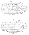
Figure 7 , an orthogonal top view of ananchor 122 and acomplementary connector 124 are shown in an assembled state according to another embodiment of the disclosure. Theanchor 122 comprises aroot rod 125 and theconnector 124 comprises atip rod 130. However, in this embodiment, each of theroot rod 125 and thetip rod 130 comprise recesses 126. In this embodiment,side jaws 132 extend spanwise across themating interface 112 and compriseteeth 134 on opposing spanwise sides of theside jaws 132 relative to themating interface 112. In some embodiments,side jaws 132 may be connected so at their top or bottom sides to generally form a C or U-shaped structure comprising theteeth 134. When assembled, any substantial centrifugal force tending to pull thetip 110 away from theroot 108 may be transferred from therecesses 126 associated with thetip rod 130 to theteeth 134 associated with thetip rod 130, from theteeth 134 associated with thetip rod 130 to the teeth associated with theroot rod 125, and from theteeth 134 associated with theroot rod 125 to therecesses 126 associated with theroot rod 125. Because the anchor surfaces 128 are acutely angled relative to thespanwise axis 106 and the source of tension theside jaws 132 will not tend to move away from theroot rod 125 and/or thetip rod 130. In some embodiments, theside jaws 132 may be biased toward each other about a jaw pin through the use of a spring and/or any other suitable mechanical biasing device. Additionally and/or alternatively, theside jaws 132 may be at least one of biased toward each other and/or spatially restrained relative to theroot rod 125 by disposing aplug 127, spacer, shim, epoxy, and/or any other suitably stiff and/or expansive material between theside jaws 132 and adjacent interior walls of theroot cavity 118 and/ortip cavity 120. Theside jaws 132 may be placed into position before a wall of theroot cavity 118 and/ortip cavity 120 are fully formed. After such placement, a remainder of theroot cavity 118 and/ortip cavity 120 may be completed to form therotor blade 104. - Referring now to
Figure 8 , an orthogonal top view of ananchor 122 and acomplementary connector 124 are shown in an assembled state according to another embodiment of the disclosure. Theanchor 122 comprises aneccentric stud 150 and theconnector 124 comprises a tension-torsion strap 152. In this embodiment, the tension-torsion strap 152 may be placed around theeccentric stud 150 to provide a force path for centrifugal forces. In some cases, the tension-torsion strap 152 may not immediately be tightly mated against theeccentric stud 150. Accordingly, in some embodiments, theeccentric stud 150 may be rotated to tighten theeccentric stud 150 against the tension-torsion strap 152. With theeccentric stud 150 in place against the tension-torsion strap 152, the two may be spatially restrained relative to each other by disposing aplug 127, spacer, shim, epoxy, and/or any other suitably stiff and/or expansive material between interior of the tension-torsion strap 152 and the exterior of theeccentric stud 150. Further, additional plugs, spacers, shims, epoxy, and/or any other suitably stiff and/or expansive materials may be placed between the interior walls of theroot cavity 118 and/ortip cavity 120 and the remainder of the tension-torsion strap 152 and/oreccentric stud 150. - Referring now to
Figure 9 , an orthogonal top view of a portion of a rotor system comprising arotor blade 104 is shown according to another embodiment of the disclosure. In this embodiment, therotor blade 104 comprises anaccess hole 900 formed in theroot 108 that allows convenient access to at least one of theanchor 122 and theconnector 124. In some embodiments, a cover may be attached to theroot 108 to cover theaccess hole 900 through the use of fasteners and/orfastener receivers 902. In some embodiments,blade balancing weights 904 may also be accessible through theaccess hole 900. - In some embodiments, a tip may be removably connected to a root without utilizing one or more of a bolt, bonding a primary load path structure, a threaded connection between the tip and the root, and/or disposing elastomeric material between substantially rigid connection interfaces between the tip and the root. In some embodiments, an anchor and a complementary connector may comprise undulating profiles and one or both of the anchor and the complementary connector may comprise elastic properties that allow insertion of the complementary connector into the anchor and may depend primarily on an interference fit and/or contact surface area dependent function for retaining the tip to the root during rotation of the rotor blade.
- At least one embodiment is disclosed and variations, combinations, and/or modifications of the embodiment(s) and/or features of the embodiment(s) made by a person having ordinary skill in the art are within the scope of the disclosure. Alternative embodiments that result from combining, integrating, and/or omitting features of the embodiment(s) are also within the scope of the disclosure. Where numerical ranges or limitations are expressly stated, such express ranges or limitations should be understood to include iterative ranges or limitations of like magnitude falling within the expressly stated ranges or limitations (e.g., from about 1 to about 10 includes, 2, 3, 4, etc.; greater than 0. 10 includes 0.11, 0.12, 0.13, etc.). For example, whenever a numerical range with a lower limit, Rl, and an upper limit, Ru, is disclosed, any number falling within the range is specifically disclosed. In particular, the following numbers within the range are specifically disclosed: R=Rl+k*(Ru-Rl), wherein k is a variable ranging from 1 percent to 100 percent with a 1 percent increment, i.e., k is 1 percent, 2 percent, 3 percent, 4 percent, 5 percent, ..., 50 percent, 51 percent, 52 percent, ..., 95 percent, 96 percent, 97 percent, 98 percent, 99 percent, or 100 percent. Unless otherwise stated, the term "about" shall mean plus or minus 10 percent of the subsequent value. Moreover, any numerical range defined by two R numbers as defined in the above is also specifically disclosed. Use of the term "optionally" with respect to any element of a claim means that the element is required, or alternatively, the element is not required, both alternatives being within the scope of the claim. Use of broader terms such as comprises, includes, and having should be understood to provide support for narrower terms such as consisting of, consisting essentially of, and comprised substantially of. Accordingly, the scope of protection is not limited by the description set out above but is defined by the claims that follow, that scope including all equivalents of the subject matter of the claims. Each and every claim is incorporated as further disclosure into the specification and the claims are embodiment(s) of the present invention.
Claims (15)
- A rotor blade, comprising:a spanwise axis;a root comprising an anchor having an anchor surface configured to form at least one of a normal angle relative to the spanwise axis and an acute angle relative to the spanwise axis; anda selectively removable tip comprising a connector having a connector surface configured to complement the anchor surface.
- A method of assembling a rotor blade, comprising:providing a root along a spanwise axis and an anchor having an anchor surface configured to form at least one of a normal angle relative to the spanwise axis and an acute angle relative to the spanwise axis;providing a selectively removable tip comprising a connector having a connector surface configured to generally complement the anchor surface; andmating the connector surface to the anchor surface.
- A rotor system, comprising:an axis of rotation; anda rotor blade comprising a spanwise axis and configured for selective rotation about the axis of rotation, the rotor blade comprising:a root comprising an anchor; anda selectively removable tip comprising a connector configured to complement the anchor, wherein the root is at least partially disposed along the spanwise axis between the tip and the axis of rotation;wherein at least a portion of the connector is located along the spanwise axis between the axis of rotation and the anchor.
- The rotor blade of claim 1, or the rotor system of claim 3, wherein the root comprises a root cavity configured to receive at least a portion of each of the anchor and the connector when the connector is assembled to the anchor; or
the method of claim 2 further comprising:disposing at least a portion of each of the anchor and the connector within a root cavity of the root. - The rotor blade of claim 1 or of claim 4, or the rotor system of claim 3 or of claim 4, wherein the root comprises a cantilevered root rod.
- The rotor blade of any preceding rotor blade claim or the rotor system of any preceding rotor system claim, wherein a recess of the anchor comprises the anchor surface.
- The rotor blade or rotor system of claim 6, wherein the recess comprises a generally triangular shape, or a generally rectangular shape.
- The rotor blade of any preceding rotor blade claim or the rotor system of any preceding rotor system claim, wherein the connector comprises a pair of opposing jaws.
- The rotor blade of claim 1 or the rotor system of claim 3 or the rotor blade or rotor system of any of claims 4 to 8, wherein the connector comprises a tooth comprising the connector surface and wherein the tooth is biased toward a recess of the root rod.
- The rotor blade of claim 1, or the rotor system of claim 3, or the rotor blade or rotor system of any of claims 4 to 8, wherein the connector comprises at least one of a torsion-tension strap and a convex tooth.
- The method of claim 4, wherein at least a portion of the connector is inserted into the root cavity prior to the mating.
- The method of claim 4, wherein the mating is performed prior to forming a root cavity of the root that is configured to receive at least a portion of each of the anchor and the connector.
- The method of claim 4, further comprising: at least one of biasing the connector surface to the anchor surface and restricting movement of the anchor surface away from the connector surface.
- The method of claim 4, wherein a force with which the mating between the connector surface mates to the anchor surface increases with an increase in centrifugal force resulting from rotation of the rotor blade about an axis of rotation; or
the rotor system of claim 3 wherein the connector comprises a pair of opposing jaws configured to bias toward each other with increasing force with an increase in centrifugal force caused by rotation of the rotor blade about the axis of rotation. - The rotor system of claim 3 or the rotor blade of claim 1, or the rotor system or rotor blade of any preceding claim, wherein: the connector comprises a tooth biased toward a recess of anchor; and/or the connector is configured to slide into engagement with the anchor.
Applications Claiming Priority (1)
| Application Number | Priority Date | Filing Date | Title |
|---|---|---|---|
| US13/789,265 US11261735B2 (en) | 2013-03-07 | 2013-03-07 | Removable rotor blade tip |
Publications (2)
| Publication Number | Publication Date |
|---|---|
| EP2774847A1 true EP2774847A1 (en) | 2014-09-10 |
| EP2774847B1 EP2774847B1 (en) | 2016-09-14 |
Family
ID=48190750
Family Applications (1)
| Application Number | Title | Priority Date | Filing Date |
|---|---|---|---|
| EP13165390.9A Active EP2774847B1 (en) | 2013-03-07 | 2013-04-25 | Removeable rotor blade tip |
Country Status (3)
| Country | Link |
|---|---|
| US (1) | US11261735B2 (en) |
| EP (1) | EP2774847B1 (en) |
| CA (1) | CA2845134C (en) |
Cited By (1)
| Publication number | Priority date | Publication date | Assignee | Title |
|---|---|---|---|---|
| CN114486148A (en) * | 2021-12-14 | 2022-05-13 | 西南科技大学 | Rotor suitable for research of propeller tip vortex flow control experiment |
Families Citing this family (6)
| Publication number | Priority date | Publication date | Assignee | Title |
|---|---|---|---|---|
| US11286036B2 (en) * | 2018-10-12 | 2022-03-29 | Textron Innovations Inc. | Ducted rotor blade tip extension |
| US11286037B2 (en) * | 2018-10-12 | 2022-03-29 | Textron Innovations Inc. | Ducted rotor blade tip extension |
| US12365453B2 (en) | 2018-10-12 | 2025-07-22 | Textron Innovations Inc. | Multi-material ducted rotor blade tip extension |
| US10988243B2 (en) * | 2019-03-15 | 2021-04-27 | Bell Textron Inc. | Tension-torsion strap |
| US11498671B2 (en) | 2019-05-13 | 2022-11-15 | Lockheed Martin Corporation | Replacement tip section for a rotor blade and method of replacing a rotor blade tip section |
| US11565799B2 (en) | 2020-06-12 | 2023-01-31 | Textron Innovations Inc. | Adjustable ducted rotor blade tip extension |
Citations (4)
| Publication number | Priority date | Publication date | Assignee | Title |
|---|---|---|---|---|
| DE638559C (en) * | 1933-08-11 | 1936-11-17 | D Aviat Louis Breguet Sa Des A | Helicopter with articulated, controllable wings |
| GB485750A (en) * | 1936-08-24 | 1938-05-24 | Jean Louis Ambroise Castelli | Towing and dropping bombs and other articles from aircraft |
| US2397132A (en) * | 1943-03-20 | 1946-03-26 | Jr Frederick R Dent | Antiflutter and vibration device for fan and propeller blades |
| US2815820A (en) * | 1955-04-19 | 1957-12-10 | Gyrodyne Company Of America In | Power folding rotor blade system for rotary wing aircraft |
Family Cites Families (18)
| Publication number | Priority date | Publication date | Assignee | Title |
|---|---|---|---|---|
| US1382849A (en) * | 1921-06-28 | Albert henry franks perl | ||
| US1878816A (en) * | 1925-12-30 | 1932-09-20 | Herbert E Bucklen Corp | Impeller |
| US2118361A (en) * | 1936-12-09 | 1938-05-24 | Jr Ethan A Schaeffer | Quick action nut |
| US2257327A (en) * | 1941-04-23 | 1941-09-30 | Carios L Bradford | Nut |
| US5263821A (en) * | 1991-01-15 | 1993-11-23 | United Technologies Corporation | Mid-beam jointed reconfigurable bearingless main rotor assembly |
| US5320494A (en) * | 1992-12-22 | 1994-06-14 | United Technologies Corporation | Helicopter rotor blade having a replaceable anhedral tip |
| US5885059A (en) | 1996-12-23 | 1999-03-23 | Sikorsky Aircraft Corporation | Composite tip cap assembly for a helicopter main rotor blade |
| US6976829B2 (en) | 2003-07-16 | 2005-12-20 | Sikorsky Aircraft Corporation | Rotor blade tip section |
| EP1584817A1 (en) * | 2004-04-07 | 2005-10-12 | Gamesa Eolica, S.A. (Sociedad Unipersonal) | Wind turbine blade |
| US7246998B2 (en) | 2004-11-18 | 2007-07-24 | Sikorsky Aircraft Corporation | Mission replaceable rotor blade tip section |
| US7762785B2 (en) * | 2007-12-10 | 2010-07-27 | Sikorsky Aircraft Corporation | Main rotor blade with integral tip section |
| NZ590008A (en) * | 2008-05-23 | 2012-06-29 | Siemens Ag | A mounting bracket device for mounting a blade of a wind turbine to a transport |
| WO2010023299A2 (en) * | 2008-08-31 | 2010-03-04 | Vestas Wind Systems A/S | A sectional blade |
| JP5249684B2 (en) * | 2008-09-04 | 2013-07-31 | 三菱重工業株式会社 | Windmill wing |
| JP5326530B2 (en) * | 2008-12-03 | 2013-10-30 | パナソニック株式会社 | Screw parts and imaging device |
| FR2948154B1 (en) * | 2009-07-16 | 2011-09-16 | Astrium Sas | DEVICE FOR ASSEMBLING WINDMILL BLADE RODS AND METHOD FOR CONNECTING WINDMILL BLADE TRUNCONS |
| GB201002249D0 (en) * | 2010-02-10 | 2010-03-31 | Walters Albert E D | Improvements in or relating to methods of manufacture |
| US9651024B2 (en) * | 2014-04-14 | 2017-05-16 | General Electric Company | Rotor blade assembly having internal loading features |
-
2013
- 2013-03-07 US US13/789,265 patent/US11261735B2/en active Active
- 2013-04-25 EP EP13165390.9A patent/EP2774847B1/en active Active
-
2014
- 2014-03-06 CA CA2845134A patent/CA2845134C/en active Active
Patent Citations (4)
| Publication number | Priority date | Publication date | Assignee | Title |
|---|---|---|---|---|
| DE638559C (en) * | 1933-08-11 | 1936-11-17 | D Aviat Louis Breguet Sa Des A | Helicopter with articulated, controllable wings |
| GB485750A (en) * | 1936-08-24 | 1938-05-24 | Jean Louis Ambroise Castelli | Towing and dropping bombs and other articles from aircraft |
| US2397132A (en) * | 1943-03-20 | 1946-03-26 | Jr Frederick R Dent | Antiflutter and vibration device for fan and propeller blades |
| US2815820A (en) * | 1955-04-19 | 1957-12-10 | Gyrodyne Company Of America In | Power folding rotor blade system for rotary wing aircraft |
Cited By (1)
| Publication number | Priority date | Publication date | Assignee | Title |
|---|---|---|---|---|
| CN114486148A (en) * | 2021-12-14 | 2022-05-13 | 西南科技大学 | Rotor suitable for research of propeller tip vortex flow control experiment |
Also Published As
| Publication number | Publication date |
|---|---|
| EP2774847B1 (en) | 2016-09-14 |
| US11261735B2 (en) | 2022-03-01 |
| CA2845134A1 (en) | 2014-09-07 |
| US20140255201A1 (en) | 2014-09-11 |
| CA2845134C (en) | 2016-10-11 |
Similar Documents
| Publication | Publication Date | Title |
|---|---|---|
| CA2845134C (en) | Removable rotor blade tip | |
| CA1321378C (en) | Rotor head for rotorcraft | |
| EP2374999B1 (en) | Composite turbine bucket assembly | |
| EP0214875B1 (en) | Damping element limiting the angular deflection of turbo machine rotor vanes | |
| EP2711293B1 (en) | Adjustable payload enclosure for wing | |
| EP2532880B1 (en) | Rotor blade for a wind turbine | |
| EP2990882B1 (en) | Balance with inertia adjustment. | |
| CA2845668A1 (en) | Mechanical system comprising a device for connection between a wearing part and the support thereof, heavy-construction machine bucket, and method for implementing said system | |
| CA2845667A1 (en) | Mechanical system comprising a device for connection between a wearing part and the support thereof, heavy-construction machine bucket, and method for implementing said system | |
| US10662814B2 (en) | Stator shroud systems | |
| KR20120088579A (en) | Blade and method of fabricating said blade | |
| KR20180054652A (en) | Geometry to increase the torque capacity of the rivet vane lever | |
| EP2774848B1 (en) | System for attaching a load to a rotorcraft, and rotorcraft | |
| EP3315403B1 (en) | Torsionally flexible beam for a blade, set of torsionally flexible beams, a rotor and an aircraft | |
| FR3094347A1 (en) | Rear engine attachment of an aircraft having shackles in two parts and aircraft comprising at least one such rear engine attachment | |
| FR3012552A1 (en) | MECHANICAL BONDING DEVICE | |
| EP3059811B1 (en) | Modular system | |
| KR20150071145A (en) | Combination structure between blade and hub of propeller by using metal member | |
| EP3698219B1 (en) | Fixing device for a bracelet | |
| MX2021005133A (en) | Compliant structures for jointed rotor blades. | |
| US9498841B2 (en) | Auxiliary device for welding spindle disks, having a damping belt, and friction welding method | |
| FR3070422B1 (en) | DAGGER ATTACHMENT WITH STRAIGHTENER VANE SEAL | |
| FR3005631A1 (en) | ELASTIC JOINT CONNECTION BETWEEN A TRAINING DAMPER AND A BLADE OF A ROTOR | |
| US9267387B2 (en) | Seal platform | |
| KR101557405B1 (en) | The impeller assembly |
Legal Events
| Date | Code | Title | Description |
|---|---|---|---|
| PUAI | Public reference made under article 153(3) epc to a published international application that has entered the european phase |
Free format text: ORIGINAL CODE: 0009012 |
|
| 17P | Request for examination filed |
Effective date: 20130425 |
|
| AK | Designated contracting states |
Kind code of ref document: A1 Designated state(s): AL AT BE BG CH CY CZ DE DK EE ES FI FR GB GR HR HU IE IS IT LI LT LU LV MC MK MT NL NO PL PT RO RS SE SI SK SM TR |
|
| AX | Request for extension of the european patent |
Extension state: BA ME |
|
| GRAP | Despatch of communication of intention to grant a patent |
Free format text: ORIGINAL CODE: EPIDOSNIGR1 |
|
| INTG | Intention to grant announced |
Effective date: 20160407 |
|
| GRAS | Grant fee paid |
Free format text: ORIGINAL CODE: EPIDOSNIGR3 |
|
| GRAA | (expected) grant |
Free format text: ORIGINAL CODE: 0009210 |
|
| AK | Designated contracting states |
Kind code of ref document: B1 Designated state(s): AL AT BE BG CH CY CZ DE DK EE ES FI FR GB GR HR HU IE IS IT LI LT LU LV MC MK MT NL NO PL PT RO RS SE SI SK SM TR |
|
| REG | Reference to a national code |
Ref country code: GB Ref legal event code: FG4D |
|
| REG | Reference to a national code |
Ref country code: CH Ref legal event code: EP |
|
| REG | Reference to a national code |
Ref country code: IE Ref legal event code: FG4D |
|
| REG | Reference to a national code |
Ref country code: AT Ref legal event code: REF Ref document number: 828654 Country of ref document: AT Kind code of ref document: T Effective date: 20161015 |
|
| REG | Reference to a national code |
Ref country code: DE Ref legal event code: R096 Ref document number: 602013011340 Country of ref document: DE |
|
| REG | Reference to a national code |
Ref country code: LT Ref legal event code: MG4D |
|
| REG | Reference to a national code |
Ref country code: NL Ref legal event code: MP Effective date: 20160914 |
|
| PG25 | Lapsed in a contracting state [announced via postgrant information from national office to epo] |
Ref country code: HR Free format text: LAPSE BECAUSE OF FAILURE TO SUBMIT A TRANSLATION OF THE DESCRIPTION OR TO PAY THE FEE WITHIN THE PRESCRIBED TIME-LIMIT Effective date: 20160914 Ref country code: RS Free format text: LAPSE BECAUSE OF FAILURE TO SUBMIT A TRANSLATION OF THE DESCRIPTION OR TO PAY THE FEE WITHIN THE PRESCRIBED TIME-LIMIT Effective date: 20160914 Ref country code: LT Free format text: LAPSE BECAUSE OF FAILURE TO SUBMIT A TRANSLATION OF THE DESCRIPTION OR TO PAY THE FEE WITHIN THE PRESCRIBED TIME-LIMIT Effective date: 20160914 Ref country code: FI Free format text: LAPSE BECAUSE OF FAILURE TO SUBMIT A TRANSLATION OF THE DESCRIPTION OR TO PAY THE FEE WITHIN THE PRESCRIBED TIME-LIMIT Effective date: 20160914 Ref country code: NO Free format text: LAPSE BECAUSE OF FAILURE TO SUBMIT A TRANSLATION OF THE DESCRIPTION OR TO PAY THE FEE WITHIN THE PRESCRIBED TIME-LIMIT Effective date: 20161214 |
|
| REG | Reference to a national code |
Ref country code: AT Ref legal event code: MK05 Ref document number: 828654 Country of ref document: AT Kind code of ref document: T Effective date: 20160914 |
|
| PG25 | Lapsed in a contracting state [announced via postgrant information from national office to epo] |
Ref country code: LV Free format text: LAPSE BECAUSE OF FAILURE TO SUBMIT A TRANSLATION OF THE DESCRIPTION OR TO PAY THE FEE WITHIN THE PRESCRIBED TIME-LIMIT Effective date: 20160914 Ref country code: SE Free format text: LAPSE BECAUSE OF FAILURE TO SUBMIT A TRANSLATION OF THE DESCRIPTION OR TO PAY THE FEE WITHIN THE PRESCRIBED TIME-LIMIT Effective date: 20160914 Ref country code: NL Free format text: LAPSE BECAUSE OF FAILURE TO SUBMIT A TRANSLATION OF THE DESCRIPTION OR TO PAY THE FEE WITHIN THE PRESCRIBED TIME-LIMIT Effective date: 20160914 Ref country code: GR Free format text: LAPSE BECAUSE OF FAILURE TO SUBMIT A TRANSLATION OF THE DESCRIPTION OR TO PAY THE FEE WITHIN THE PRESCRIBED TIME-LIMIT Effective date: 20161215 |
|
| REG | Reference to a national code |
Ref country code: FR Ref legal event code: PLFP Year of fee payment: 5 |
|
| PG25 | Lapsed in a contracting state [announced via postgrant information from national office to epo] |
Ref country code: EE Free format text: LAPSE BECAUSE OF FAILURE TO SUBMIT A TRANSLATION OF THE DESCRIPTION OR TO PAY THE FEE WITHIN THE PRESCRIBED TIME-LIMIT Effective date: 20160914 Ref country code: RO Free format text: LAPSE BECAUSE OF FAILURE TO SUBMIT A TRANSLATION OF THE DESCRIPTION OR TO PAY THE FEE WITHIN THE PRESCRIBED TIME-LIMIT Effective date: 20160914 |
|
| PG25 | Lapsed in a contracting state [announced via postgrant information from national office to epo] |
Ref country code: SK Free format text: LAPSE BECAUSE OF FAILURE TO SUBMIT A TRANSLATION OF THE DESCRIPTION OR TO PAY THE FEE WITHIN THE PRESCRIBED TIME-LIMIT Effective date: 20160914 Ref country code: SM Free format text: LAPSE BECAUSE OF FAILURE TO SUBMIT A TRANSLATION OF THE DESCRIPTION OR TO PAY THE FEE WITHIN THE PRESCRIBED TIME-LIMIT Effective date: 20160914 Ref country code: PT Free format text: LAPSE BECAUSE OF FAILURE TO SUBMIT A TRANSLATION OF THE DESCRIPTION OR TO PAY THE FEE WITHIN THE PRESCRIBED TIME-LIMIT Effective date: 20170116 Ref country code: CZ Free format text: LAPSE BECAUSE OF FAILURE TO SUBMIT A TRANSLATION OF THE DESCRIPTION OR TO PAY THE FEE WITHIN THE PRESCRIBED TIME-LIMIT Effective date: 20160914 Ref country code: AT Free format text: LAPSE BECAUSE OF FAILURE TO SUBMIT A TRANSLATION OF THE DESCRIPTION OR TO PAY THE FEE WITHIN THE PRESCRIBED TIME-LIMIT Effective date: 20160914 Ref country code: BE Free format text: LAPSE BECAUSE OF FAILURE TO SUBMIT A TRANSLATION OF THE DESCRIPTION OR TO PAY THE FEE WITHIN THE PRESCRIBED TIME-LIMIT Effective date: 20160914 Ref country code: IS Free format text: LAPSE BECAUSE OF FAILURE TO SUBMIT A TRANSLATION OF THE DESCRIPTION OR TO PAY THE FEE WITHIN THE PRESCRIBED TIME-LIMIT Effective date: 20170114 Ref country code: BG Free format text: LAPSE BECAUSE OF FAILURE TO SUBMIT A TRANSLATION OF THE DESCRIPTION OR TO PAY THE FEE WITHIN THE PRESCRIBED TIME-LIMIT Effective date: 20161214 Ref country code: PL Free format text: LAPSE BECAUSE OF FAILURE TO SUBMIT A TRANSLATION OF THE DESCRIPTION OR TO PAY THE FEE WITHIN THE PRESCRIBED TIME-LIMIT Effective date: 20160914 Ref country code: ES Free format text: LAPSE BECAUSE OF FAILURE TO SUBMIT A TRANSLATION OF THE DESCRIPTION OR TO PAY THE FEE WITHIN THE PRESCRIBED TIME-LIMIT Effective date: 20160914 |
|
| REG | Reference to a national code |
Ref country code: DE Ref legal event code: R097 Ref document number: 602013011340 Country of ref document: DE |
|
| PLBE | No opposition filed within time limit |
Free format text: ORIGINAL CODE: 0009261 |
|
| STAA | Information on the status of an ep patent application or granted ep patent |
Free format text: STATUS: NO OPPOSITION FILED WITHIN TIME LIMIT |
|
| PG25 | Lapsed in a contracting state [announced via postgrant information from national office to epo] |
Ref country code: DK Free format text: LAPSE BECAUSE OF FAILURE TO SUBMIT A TRANSLATION OF THE DESCRIPTION OR TO PAY THE FEE WITHIN THE PRESCRIBED TIME-LIMIT Effective date: 20160914 |
|
| 26N | No opposition filed |
Effective date: 20170615 |
|
| PG25 | Lapsed in a contracting state [announced via postgrant information from national office to epo] |
Ref country code: SI Free format text: LAPSE BECAUSE OF FAILURE TO SUBMIT A TRANSLATION OF THE DESCRIPTION OR TO PAY THE FEE WITHIN THE PRESCRIBED TIME-LIMIT Effective date: 20160914 |
|
| REG | Reference to a national code |
Ref country code: CH Ref legal event code: PL |
|
| REG | Reference to a national code |
Ref country code: IE Ref legal event code: MM4A |
|
| PG25 | Lapsed in a contracting state [announced via postgrant information from national office to epo] |
Ref country code: MC Free format text: LAPSE BECAUSE OF FAILURE TO SUBMIT A TRANSLATION OF THE DESCRIPTION OR TO PAY THE FEE WITHIN THE PRESCRIBED TIME-LIMIT Effective date: 20160914 |
|
| PG25 | Lapsed in a contracting state [announced via postgrant information from national office to epo] |
Ref country code: CH Free format text: LAPSE BECAUSE OF NON-PAYMENT OF DUE FEES Effective date: 20170430 Ref country code: LI Free format text: LAPSE BECAUSE OF NON-PAYMENT OF DUE FEES Effective date: 20170430 Ref country code: LU Free format text: LAPSE BECAUSE OF NON-PAYMENT OF DUE FEES Effective date: 20170425 |
|
| REG | Reference to a national code |
Ref country code: FR Ref legal event code: PLFP Year of fee payment: 6 |
|
| PG25 | Lapsed in a contracting state [announced via postgrant information from national office to epo] |
Ref country code: IE Free format text: LAPSE BECAUSE OF NON-PAYMENT OF DUE FEES Effective date: 20170425 |
|
| PG25 | Lapsed in a contracting state [announced via postgrant information from national office to epo] |
Ref country code: MT Free format text: LAPSE BECAUSE OF NON-PAYMENT OF DUE FEES Effective date: 20170425 |
|
| PG25 | Lapsed in a contracting state [announced via postgrant information from national office to epo] |
Ref country code: AL Free format text: LAPSE BECAUSE OF FAILURE TO SUBMIT A TRANSLATION OF THE DESCRIPTION OR TO PAY THE FEE WITHIN THE PRESCRIBED TIME-LIMIT Effective date: 20160914 |
|
| PG25 | Lapsed in a contracting state [announced via postgrant information from national office to epo] |
Ref country code: HU Free format text: LAPSE BECAUSE OF FAILURE TO SUBMIT A TRANSLATION OF THE DESCRIPTION OR TO PAY THE FEE WITHIN THE PRESCRIBED TIME-LIMIT; INVALID AB INITIO Effective date: 20130425 |
|
| PG25 | Lapsed in a contracting state [announced via postgrant information from national office to epo] |
Ref country code: CY Free format text: LAPSE BECAUSE OF FAILURE TO SUBMIT A TRANSLATION OF THE DESCRIPTION OR TO PAY THE FEE WITHIN THE PRESCRIBED TIME-LIMIT Effective date: 20160914 |
|
| PG25 | Lapsed in a contracting state [announced via postgrant information from national office to epo] |
Ref country code: MK Free format text: LAPSE BECAUSE OF FAILURE TO SUBMIT A TRANSLATION OF THE DESCRIPTION OR TO PAY THE FEE WITHIN THE PRESCRIBED TIME-LIMIT Effective date: 20160914 |
|
| PG25 | Lapsed in a contracting state [announced via postgrant information from national office to epo] |
Ref country code: TR Free format text: LAPSE BECAUSE OF FAILURE TO SUBMIT A TRANSLATION OF THE DESCRIPTION OR TO PAY THE FEE WITHIN THE PRESCRIBED TIME-LIMIT Effective date: 20160914 |
|
| P01 | Opt-out of the competence of the unified patent court (upc) registered |
Effective date: 20230602 |
|
| PGFP | Annual fee paid to national office [announced via postgrant information from national office to epo] |
Ref country code: GB Payment date: 20260427 Year of fee payment: 14 |
|
| PGFP | Annual fee paid to national office [announced via postgrant information from national office to epo] |
Ref country code: IT Payment date: 20260421 Year of fee payment: 14 |
|
| PGFP | Annual fee paid to national office [announced via postgrant information from national office to epo] |
Ref country code: DE Payment date: 20260429 Year of fee payment: 14 |
|
| PGFP | Annual fee paid to national office [announced via postgrant information from national office to epo] |
Ref country code: FR Payment date: 20260427 Year of fee payment: 14 |