EP2774842A1 - Propeller blade with relatively movable counterweight - Google Patents
Propeller blade with relatively movable counterweight Download PDFInfo
- Publication number
- EP2774842A1 EP2774842A1 EP14150272.4A EP14150272A EP2774842A1 EP 2774842 A1 EP2774842 A1 EP 2774842A1 EP 14150272 A EP14150272 A EP 14150272A EP 2774842 A1 EP2774842 A1 EP 2774842A1
- Authority
- EP
- European Patent Office
- Prior art keywords
- counterweight
- blades
- blade
- rotor
- hub
- Prior art date
- Legal status (The legal status is an assumption and is not a legal conclusion. Google has not performed a legal analysis and makes no representation as to the accuracy of the status listed.)
- Granted
Links
Images


Classifications
-
- F—MECHANICAL ENGINEERING; LIGHTING; HEATING; WEAPONS; BLASTING
- F01—MACHINES OR ENGINES IN GENERAL; ENGINE PLANTS IN GENERAL; STEAM ENGINES
- F01D—NON-POSITIVE DISPLACEMENT MACHINES OR ENGINES, e.g. STEAM TURBINES
- F01D7/00—Rotors with blades adjustable in operation; Control thereof
-
- B—PERFORMING OPERATIONS; TRANSPORTING
- B64—AIRCRAFT; AVIATION; COSMONAUTICS
- B64C—AEROPLANES; HELICOPTERS
- B64C11/00—Propellers, e.g. of ducted type; Features common to propellers and rotors for rotorcraft
- B64C11/30—Blade pitch-changing mechanisms
- B64C11/32—Blade pitch-changing mechanisms mechanical
- B64C11/34—Blade pitch-changing mechanisms mechanical automatic
- B64C11/346—Blade pitch-changing mechanisms mechanical automatic actuated by the centrifugal force or the aerodynamic drag acting on auxiliary masses or surfaces
-
- B—PERFORMING OPERATIONS; TRANSPORTING
- B64—AIRCRAFT; AVIATION; COSMONAUTICS
- B64C—AEROPLANES; HELICOPTERS
- B64C11/00—Propellers, e.g. of ducted type; Features common to propellers and rotors for rotorcraft
- B64C11/30—Blade pitch-changing mechanisms
- B64C11/38—Blade pitch-changing mechanisms fluid, e.g. hydraulic
- B64C11/385—Blade pitch-changing mechanisms fluid, e.g. hydraulic comprising feathering, braking or stopping systems
Definitions
- This application relates to a counterweight for use in a variable pitch propeller blade assembly.
- Propeller rotors typically include a plurality of blades having airfoils.
- the rotor is provided with a pitch change mechanism that may be hydraulically powered.
- the pitch change mechanism changes an angle of incidence of the airfoils.
- counterweights have been fixed to the blade in the past with the counterweight designed to be attached to a base of the blade and produce a twisting moment on the blade when the propeller rotor rotates, such that in that moment on the blade is in a direction to increase pitch.
- the counterweight To optimize the design of the counterweight, it is desirable to place the counterweight at a largest radius from a blade pitch change axis as allowable.
- the blade pitch angle must be capable of movement from a full reverse position to a feather position.
- the feather position is essentially the position at which the blade is parallel to an approaching air flow.
- the counterweight must be capable of passing the adjacent blades. This limits the radius that may be utilized between the counterweight and the blade rotational axis.
- a propeller rotor has a hub mounting a plurality of blades.
- a counterweight is movably mounted on the blade.
- a pitch change mechanism for changing an angle of incidence of an airfoil is associated with each of the blades.
- the counterweight twists the blades toward an increased pitch direction should the pitch change mechanism fail.
- a stop member stops rotation of the counterweight as the blade moves to a feather position.
- a prior art propeller rotor 20 is illustrated in Figure 1 having a blade 22 extending inwardly to an inner trunnion portion 24.
- the blade 22 has a root 23 mounted in a hub 26.
- a hydraulic piston 28 receives hydraulic fluid to actuate a connection 29 to change an angle of incidence of an airfoil 21 associated with the blade 22 through the trunnion location 24.
- this drive arrangement through the hydraulic piston 28 and connection 29 may fail or the hydraulic supply to piston 28 may fail. This could lead to the angle of incidence of the blade airfoil 21 moving toward an undesired position.
- a counterweight 30 is attached by an arm 31 to the blade 22. This counterweight has been fixed in the prior art.
- Figure 2A shows the arrangement of two adjacent blades 22 each having an arm 31 connecting a counterweight 30. In a flight position, the blades 22 may be positioned as shown in Figure 2A .
- the blades may sometimes be moved to a "feather" position.
- the feather position is a position at which the blades are parallel to an approaching, or forward, direction of the airstream. A worker of ordinary skill in the art would recognize when the feather position should be taken.
- FIG 3A shows an improved propeller 99.
- a blade 106 has a counterweight 100 attached by an arm 102 through a collar 104.
- the collar 104 is rotatable upon a groove 105 in a base of the blade 106.
- a pin 116 is fixed to the blade base and, as shown in Figure 3B , a groove 118 in the collar 104 extends between ends 115 and 117. When the pin 116 abuts one of the ends 115 and 117, the counterweight will be able to transmit torque to the blade 106 to provide the safety function mentioned above.
- the blade has its base mounted in a hub 112, and there is actuation structure 108/110 as in the prior art.
- a hub stop pin 114 is included in hub 112.
- Figure 4A shows a normal flight position.
- a torque T is transmitted from the counterweight 100 to the blade 106 since an end of the groove 118 abuts the pin 116.
- Figure 4B shows adjacent blades 106 in a reverse position. Again, the pin 116 abuts an end of the groove 118, and a torque will be applied to the blade in the event the variable pitch mechanism fails.
- Figure 4C shows the movement to the feather position.
- the arm 102 abuts the hub stop pin 114.
- the contact occurs at a point during movement to the feather position. This point is the highest blade angle that requires counterweight protection during normal operation. That is, counterweight 100 may move for a portion of the movement to the feather position, but is stopped at some point such that the counterweight will not cross the envelope E.
- the end 117 is now spaced from the pin 116. This means that the blade 106 has rotated further than the arm 102 and counterweight 100.
- the counterweight 100 can now be positioned further from a central axis X about which the pitch of the blades 106 rotates. Stated another way, the arm 102 can be made much longer than in the prior art because the counterweight 100 need not pass the envelope E.
Landscapes
- Engineering & Computer Science (AREA)
- Mechanical Engineering (AREA)
- Aviation & Aerospace Engineering (AREA)
- General Engineering & Computer Science (AREA)
- Physics & Mathematics (AREA)
- Fluid Mechanics (AREA)
- Structures Of Non-Positive Displacement Pumps (AREA)
Abstract
Description
- This application relates to a counterweight for use in a variable pitch propeller blade assembly.
- Propeller rotors typically include a plurality of blades having airfoils. The rotor is provided with a pitch change mechanism that may be hydraulically powered. The pitch change mechanism changes an angle of incidence of the airfoils.
- At times, the hydraulic power for changing the pitch of the airfoil has failed. In such a case, it is desirable to increase the pitch angle, rather than allow forces on the unpowered blade to drive the blade airfoil toward a decreased pitch angle.
- To this end, counterweights have been fixed to the blade in the past with the counterweight designed to be attached to a base of the blade and produce a twisting moment on the blade when the propeller rotor rotates, such that in that moment on the blade is in a direction to increase pitch.
- To optimize the design of the counterweight, it is desirable to place the counterweight at a largest radius from a blade pitch change axis as allowable. However, the blade pitch angle must be capable of movement from a full reverse position to a feather position. The feather position is essentially the position at which the blade is parallel to an approaching air flow.
- To achieve the transition between the reverse and feather positions, the counterweight must be capable of passing the adjacent blades. This limits the radius that may be utilized between the counterweight and the blade rotational axis.
- A propeller rotor has a hub mounting a plurality of blades. A counterweight is movably mounted on the blade. A pitch change mechanism for changing an angle of incidence of an airfoil is associated with each of the blades. The counterweight twists the blades toward an increased pitch direction should the pitch change mechanism fail. A stop member stops rotation of the counterweight as the blade moves to a feather position.
- These and other features may be best understood from the following drawings and specification.
-
-
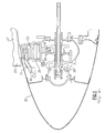
Figure 1 shows a prior art propeller rotor. -
Figure 2A schematically shows a feature of the prior art rotor. -
Figure 2B shows another feather of the prior art rotor. -
Figure 3A shows an embodiment of an improved rotor. -
Figure 3B shows a detail of theFigure 3A arrangement. -
Figure 4A schematically shows the improved counterweight in a flight position. -
Figure 4B shows the improved counterweight in a reverse position. -
Figure 4C shows the improved counterweight in a feather position. - A prior
art propeller rotor 20 is illustrated inFigure 1 having ablade 22 extending inwardly to aninner trunnion portion 24. Theblade 22 has aroot 23 mounted in ahub 26. Ahydraulic piston 28 receives hydraulic fluid to actuate aconnection 29 to change an angle of incidence of anairfoil 21 associated with theblade 22 through thetrunnion location 24. - At times, this drive arrangement through the
hydraulic piston 28 andconnection 29 may fail or the hydraulic supply topiston 28 may fail. This could lead to the angle of incidence of theblade airfoil 21 moving toward an undesired position. Thus, acounterweight 30 is attached by anarm 31 to theblade 22. This counterweight has been fixed in the prior art. -
Figure 2A shows the arrangement of twoadjacent blades 22 each having anarm 31 connecting acounterweight 30. In a flight position, theblades 22 may be positioned as shown inFigure 2A . - The blades may sometimes be moved to a "feather" position. Essentially, the feather position is a position at which the blades are parallel to an approaching, or forward, direction of the airstream. A worker of ordinary skill in the art would recognize when the feather position should be taken.
- When moving from the position of
Figure 2A to the feather position ofFigure 2B , thecounterweight 30 must pass outer envelope E of the hub and blade. Thus, a clearance C must be maintained. This limits the distance through which thearm 31 may extend from an axis X. -
Figure 3A shows an improvedpropeller 99. Ablade 106 has acounterweight 100 attached by anarm 102 through acollar 104. Thecollar 104 is rotatable upon agroove 105 in a base of theblade 106. Apin 116 is fixed to the blade base and, as shown inFigure 3B , agroove 118 in thecollar 104 extends betweenends pin 116 abuts one of theends blade 106 to provide the safety function mentioned above. Although shown schematically, the blade has its base mounted in ahub 112, and there isactuation structure 108/110 as in the prior art. Ahub stop pin 114 is included inhub 112. -
Figure 4A shows a normal flight position. A torque T is transmitted from thecounterweight 100 to theblade 106 since an end of thegroove 118 abuts thepin 116. -
Figure 4B showsadjacent blades 106 in a reverse position. Again, thepin 116 abuts an end of thegroove 118, and a torque will be applied to the blade in the event the variable pitch mechanism fails. -
Figure 4C shows the movement to the feather position. In the feather position, thearm 102 abuts the hub stoppin 114. The contact occurs at a point during movement to the feather position. This point is the highest blade angle that requires counterweight protection during normal operation. That is,counterweight 100 may move for a portion of the movement to the feather position, but is stopped at some point such that the counterweight will not cross the envelope E. As shown, theend 117 is now spaced from thepin 116. This means that theblade 106 has rotated further than thearm 102 andcounterweight 100. As can be appreciated, thecounterweight 100 can now be positioned further from a central axis X about which the pitch of theblades 106 rotates. Stated another way, thearm 102 can be made much longer than in the prior art because thecounterweight 100 need not pass the envelope E. - Although an embodiment of this invention has been disclosed, a worker of ordinary skill in this art would recognize that certain modifications would come within the scope of this invention. For that reason, the following claims should be studied to determine the true scope and content of this invention.
Claims (11)
- A propeller rotor (99) comprising:a rotor mounting a plurality of blades (106), said blades (106) having a root mounted in a hub (112) of said rotor and a counterweight (100) movably mounted on said blades (106);a pitch change mechanism for changing an angle of incidence of an airfoil associated with said blades (105) and said counterweight (100) for biasing said blades (106) toward an increased pitch direction should said pitch change mechanism fail; anda stop member (114) for stopping rotation of said counterweight (100) and said counterweight (100) with said blade (106) as said blade moves to a feathered position.
- A propeller rotor (99) comprising:a rotor mounting a plurality of blades (106), said blades (106) having a root mounted in a hub (112) of said rotor and a counterweight (100) movably mounted on said blades (106);a pitch change mechanism for changing an angle of incidence of an airfoil associated with said blades (105) and said counterweight (100) for biasing said blades (106) toward an increased pitch direction should said pitch change mechanism fail; anda stop member (114) for stopping rotation of said counterweight (100) as said blade moves to a feathered position.
- The propeller rotor as set forth in claim 1 or 2, wherein said stop (114) includes a stop pin (114) mounted on said hub (112).
- The propeller rotor as set forth in any preceding claim, wherein said blade (106) in said feather position includes said airfoils being moved generally parallel to an approaching direction of air.
- The propeller rotor as set forth in any preceding claim, wherein said counterweight (100) is mounted to said blades (106) through an arm (102), and said arm (102) is connected to a collar (104) which is rotatable about a base of said blade (106).
- The propeller rotor as set forth in claim 5, wherein said collar (104) has a groove (105) with circumferential ends (115; 117), and said hub (112) includes a hub pin (116), said hub pin (116) contacting one of said ends (115; 117) of said groove (105) such that said counterweight (100) transmits torque to said blade (106).
- The propeller rotor as set forth in claim 6, wherein when said counterweight (100) contacts said stop (114), said hub pin (116) is spaced from said end (115; 117).
- The propeller rotor as set forth in any of claims 5 to 7, wherein said stop (114) contacts said arm (102).
- The propeller rotor as set forth in any of claims 5 to 8, wherein said stop (114) stops further rotation of said arm (102) and said counterweight (100) before said counterweight (100) will cross an envelope of movement (E) of a hub (112) and blade (106) of an adjacent one of said plurality of blades (106).
- A method comprising:mounting a plurality of blades (106) in a hub (112) of a rotor (99) and movably mounting a counterweight (100) on each said blade (105);changing an angle of incidence of an airfoil associated with each of said blades (106) with a pitch change mechanism, and said counterweight (100) twisting said blades (106) toward an increased pitch direction should said pitch change mechanism fail; andstopping rotation of said counterweight (100) when said blade (106) moves to a feather position.
- The method as set forth in claim 10, wherein said moving said blades (106) to said feather position includes moving said airfoils generally parallel to an approaching direction of air.
Applications Claiming Priority (1)
| Application Number | Priority Date | Filing Date | Title |
|---|---|---|---|
| US13/735,419 US9458730B2 (en) | 2013-01-07 | 2013-01-07 | Propeller blade with relatively movable counterweight |
Publications (2)
| Publication Number | Publication Date |
|---|---|
| EP2774842A1 true EP2774842A1 (en) | 2014-09-10 |
| EP2774842B1 EP2774842B1 (en) | 2017-03-08 |
Family
ID=49918525
Family Applications (1)
| Application Number | Title | Priority Date | Filing Date |
|---|---|---|---|
| EP14150272.4A Active EP2774842B1 (en) | 2013-01-07 | 2014-01-07 | Propeller blade with relatively movable counterweight |
Country Status (2)
| Country | Link |
|---|---|
| US (1) | US9458730B2 (en) |
| EP (1) | EP2774842B1 (en) |
Cited By (1)
| Publication number | Priority date | Publication date | Assignee | Title |
|---|---|---|---|---|
| EP2865593A1 (en) * | 2013-10-25 | 2015-04-29 | Hamilton Sundstrand Corporation | Pivoting blade counterweight |
Families Citing this family (8)
| Publication number | Priority date | Publication date | Assignee | Title |
|---|---|---|---|---|
| FR3006988B1 (en) * | 2013-06-17 | 2015-07-03 | Snecma | SPHERICAL CALOTE SHAFT BLADE PIVOT |
| US10533436B2 (en) * | 2015-11-04 | 2020-01-14 | General Electric Company | Centerline-mounted hydraulic pitch change mechanism actuator |
| US10436151B2 (en) | 2015-11-17 | 2019-10-08 | General Electric Company | Modular fan for a gas turbine engine |
| EP3323714B1 (en) | 2016-11-21 | 2019-07-03 | Ratier-Figeac SAS | Propeller counterweight |
| WO2018187844A1 (en) * | 2017-04-13 | 2018-10-18 | Iridium Dynamics Pty Ltd | Dual flight mode aircraft |
| US11795964B2 (en) * | 2021-07-16 | 2023-10-24 | General Electric Company | Levered counterweight feathering system |
| US12601271B2 (en) | 2022-10-21 | 2026-04-14 | General Electric Company | Variable pitch fan of a gas turbine engine |
| EP4617168A1 (en) * | 2024-03-14 | 2025-09-17 | Ratier-Figeac SAS | Propeller assembly |
Citations (3)
| Publication number | Priority date | Publication date | Assignee | Title |
|---|---|---|---|---|
| GB460921A (en) * | 1934-08-08 | 1937-02-08 | Gustav Schwarz G M B H | Variable pitch propellers |
| US2146334A (en) * | 1935-01-21 | 1939-02-07 | Caria Ugo De | Air propeller with automatically variable pitch |
| EP0200337A2 (en) * | 1985-05-01 | 1986-11-05 | The Cessna Aircraft Company | Controllable pitch aircraft propeller |
Family Cites Families (18)
| Publication number | Priority date | Publication date | Assignee | Title |
|---|---|---|---|---|
| USRE18957E (en) * | 1933-09-26 | Propeller | ||
| US992985A (en) * | 1910-02-07 | 1911-05-23 | Oliver B Ramp | Motor. |
| US3380535A (en) * | 1965-12-27 | 1968-04-30 | Hartzell Propeller Inc | Constant speed and reversible aircraft propeller |
| NL7416097A (en) * | 1974-12-11 | 1976-06-15 | Buro Voor Wetenschappelijke En | MILL. |
| US4083651A (en) * | 1976-08-17 | 1978-04-11 | United Technologies Corporation | Wind turbine with automatic pitch and yaw control |
| US4111601A (en) * | 1977-02-02 | 1978-09-05 | Richard Joseph G | Adjustable windmill |
| GB8517474D0 (en) | 1985-07-10 | 1985-08-14 | Dowty Rotol Ltd | Variable-pitch bladed rotors |
| US4718821A (en) * | 1986-06-04 | 1988-01-12 | Clancy Brian D | Windmill blade |
| US4948339A (en) | 1989-01-23 | 1990-08-14 | General Electric Company | Propeller blade counterweight |
| US5304038A (en) | 1992-01-03 | 1994-04-19 | Bird-Johnson Company | Built-up marine propeller blade balancing |
| US5415524A (en) | 1993-06-01 | 1995-05-16 | Gamble; Christopher L. | Fluid propulsion device |
| US7581929B2 (en) | 2005-10-13 | 2009-09-01 | Hamilton Sundstrand Corporation | Rotational airfoil balance system |
| US8267656B2 (en) | 2006-03-08 | 2012-09-18 | Hamilton Sundstrand Corporation | Propeller pitch lock system |
| US8070449B2 (en) | 2008-04-29 | 2011-12-06 | Absolute Turn, Inc. | Wind turbine |
| ES1068777Y (en) * | 2008-09-25 | 2009-03-01 | Sonkyo S L | DEVICE FOR REGULATING THE PASSENGER PASS OF A WINDER |
| US8167553B2 (en) | 2009-06-09 | 2012-05-01 | Hamilton Sundstrand Corporation | Electrical system for driving a propeller pitch change mechanism |
| US8172530B2 (en) | 2009-06-09 | 2012-05-08 | Hamilton Sundstrand Corporation | Pitch change actuation system for a counter-rotating propeller |
| US8277182B2 (en) | 2009-07-02 | 2012-10-02 | Hamilton Sundstrand Corporation | Remote pitch controller for a variable pitch propeller |
-
2013
- 2013-01-07 US US13/735,419 patent/US9458730B2/en active Active
-
2014
- 2014-01-07 EP EP14150272.4A patent/EP2774842B1/en active Active
Patent Citations (3)
| Publication number | Priority date | Publication date | Assignee | Title |
|---|---|---|---|---|
| GB460921A (en) * | 1934-08-08 | 1937-02-08 | Gustav Schwarz G M B H | Variable pitch propellers |
| US2146334A (en) * | 1935-01-21 | 1939-02-07 | Caria Ugo De | Air propeller with automatically variable pitch |
| EP0200337A2 (en) * | 1985-05-01 | 1986-11-05 | The Cessna Aircraft Company | Controllable pitch aircraft propeller |
Cited By (2)
| Publication number | Priority date | Publication date | Assignee | Title |
|---|---|---|---|---|
| EP2865593A1 (en) * | 2013-10-25 | 2015-04-29 | Hamilton Sundstrand Corporation | Pivoting blade counterweight |
| US9527579B2 (en) | 2013-10-25 | 2016-12-27 | Hamilton Sundstrand Corporation | Pivoting blade counterweight |
Also Published As
| Publication number | Publication date |
|---|---|
| EP2774842B1 (en) | 2017-03-08 |
| US20140193253A1 (en) | 2014-07-10 |
| US9458730B2 (en) | 2016-10-04 |
Similar Documents
| Publication | Publication Date | Title |
|---|---|---|
| EP2774842B1 (en) | Propeller blade with relatively movable counterweight | |
| JP5753925B2 (en) | Duct type rotor for aircraft and rotorcraft | |
| US9657582B2 (en) | Gimbaled tail rotor hub with spherical elastomeric centrifugal force bearing for blade retention and pitch change articulation | |
| US8529205B2 (en) | Passive cyclic pitch control | |
| EP2865593B1 (en) | Pivoting blade counterweight | |
| WO2011078684A3 (en) | Rotor assembly | |
| EP3080402B1 (en) | Blade flow deflector | |
| CN105377695B (en) | Spherical crown shaped air propeller blade pivot | |
| EP2980401B1 (en) | Pitch drive system with lubrication arrangement | |
| JP6424254B2 (en) | Rotor and aircraft provided with such rotor | |
| US10023304B2 (en) | Tail rotor actuation system | |
| EP2801520A1 (en) | Drive system for a high lift system of an aircraft and method for detecting a misalignment between a transmission shaft and an opening in a drive system for a high lift system of an aircraft | |
| EP2343239B1 (en) | Variable pitch propeller assembly with torque compensation and method | |
| US9517839B2 (en) | Electromechanical linear actuator for in blade rotor control | |
| EP0159805B1 (en) | Wind turbine operated electrical generator system | |
| EP3293113B1 (en) | Rotor for a hover-capable aircraft and related method of control | |
| EP2660150B1 (en) | Multi-element rotor blade | |
| CN107709156B (en) | Device for controlling a propeller of a turboprop engine with variable-pitch blades | |
| EP3374262B1 (en) | Rotor blade structures | |
| CN102619736A (en) | Executive mechanism of air-intake-adjustable flow guide cascade of oxygen compressor | |
| HK1146101B (en) | Control system for a vertical axis wind turbine |
Legal Events
| Date | Code | Title | Description |
|---|---|---|---|
| PUAI | Public reference made under article 153(3) epc to a published international application that has entered the european phase |
Free format text: ORIGINAL CODE: 0009012 |
|
| 17P | Request for examination filed |
Effective date: 20140107 |
|
| AK | Designated contracting states |
Kind code of ref document: A1 Designated state(s): AL AT BE BG CH CY CZ DE DK EE ES FI FR GB GR HR HU IE IS IT LI LT LU LV MC MK MT NL NO PL PT RO RS SE SI SK SM TR |
|
| AX | Request for extension of the european patent |
Extension state: BA ME |
|
| R17P | Request for examination filed (corrected) |
Effective date: 20150116 |
|
| RBV | Designated contracting states (corrected) |
Designated state(s): AL AT BE BG CH CY CZ DE DK EE ES FI FR GB GR HR HU IE IS IT LI LT LU LV MC MK MT NL NO PL PT RO RS SE SI SK SM TR |
|
| GRAP | Despatch of communication of intention to grant a patent |
Free format text: ORIGINAL CODE: EPIDOSNIGR1 |
|
| INTG | Intention to grant announced |
Effective date: 20161025 |
|
| GRAS | Grant fee paid |
Free format text: ORIGINAL CODE: EPIDOSNIGR3 |
|
| GRAA | (expected) grant |
Free format text: ORIGINAL CODE: 0009210 |
|
| AK | Designated contracting states |
Kind code of ref document: B1 Designated state(s): AL AT BE BG CH CY CZ DE DK EE ES FI FR GB GR HR HU IE IS IT LI LT LU LV MC MK MT NL NO PL PT RO RS SE SI SK SM TR |
|
| REG | Reference to a national code |
Ref country code: GB Ref legal event code: FG4D |
|
| REG | Reference to a national code |
Ref country code: CH Ref legal event code: EP Ref country code: AT Ref legal event code: REF Ref document number: 873264 Country of ref document: AT Kind code of ref document: T Effective date: 20170315 |
|
| REG | Reference to a national code |
Ref country code: IE Ref legal event code: FG4D |
|
| REG | Reference to a national code |
Ref country code: DE Ref legal event code: R096 Ref document number: 602014007267 Country of ref document: DE |
|
| REG | Reference to a national code |
Ref country code: LT Ref legal event code: MG4D |
|
| REG | Reference to a national code |
Ref country code: NL Ref legal event code: MP Effective date: 20170308 |
|
| PG25 | Lapsed in a contracting state [announced via postgrant information from national office to epo] |
Ref country code: HR Free format text: LAPSE BECAUSE OF FAILURE TO SUBMIT A TRANSLATION OF THE DESCRIPTION OR TO PAY THE FEE WITHIN THE PRESCRIBED TIME-LIMIT Effective date: 20170308 Ref country code: GR Free format text: LAPSE BECAUSE OF FAILURE TO SUBMIT A TRANSLATION OF THE DESCRIPTION OR TO PAY THE FEE WITHIN THE PRESCRIBED TIME-LIMIT Effective date: 20170609 Ref country code: NO Free format text: LAPSE BECAUSE OF FAILURE TO SUBMIT A TRANSLATION OF THE DESCRIPTION OR TO PAY THE FEE WITHIN THE PRESCRIBED TIME-LIMIT Effective date: 20170608 Ref country code: LT Free format text: LAPSE BECAUSE OF FAILURE TO SUBMIT A TRANSLATION OF THE DESCRIPTION OR TO PAY THE FEE WITHIN THE PRESCRIBED TIME-LIMIT Effective date: 20170308 Ref country code: FI Free format text: LAPSE BECAUSE OF FAILURE TO SUBMIT A TRANSLATION OF THE DESCRIPTION OR TO PAY THE FEE WITHIN THE PRESCRIBED TIME-LIMIT Effective date: 20170308 |
|
| REG | Reference to a national code |
Ref country code: AT Ref legal event code: MK05 Ref document number: 873264 Country of ref document: AT Kind code of ref document: T Effective date: 20170308 |
|
| PG25 | Lapsed in a contracting state [announced via postgrant information from national office to epo] |
Ref country code: ES Free format text: LAPSE BECAUSE OF FAILURE TO SUBMIT A TRANSLATION OF THE DESCRIPTION OR TO PAY THE FEE WITHIN THE PRESCRIBED TIME-LIMIT Effective date: 20170308 Ref country code: BG Free format text: LAPSE BECAUSE OF FAILURE TO SUBMIT A TRANSLATION OF THE DESCRIPTION OR TO PAY THE FEE WITHIN THE PRESCRIBED TIME-LIMIT Effective date: 20170608 Ref country code: SE Free format text: LAPSE BECAUSE OF FAILURE TO SUBMIT A TRANSLATION OF THE DESCRIPTION OR TO PAY THE FEE WITHIN THE PRESCRIBED TIME-LIMIT Effective date: 20170308 Ref country code: RS Free format text: LAPSE BECAUSE OF FAILURE TO SUBMIT A TRANSLATION OF THE DESCRIPTION OR TO PAY THE FEE WITHIN THE PRESCRIBED TIME-LIMIT Effective date: 20170308 Ref country code: LV Free format text: LAPSE BECAUSE OF FAILURE TO SUBMIT A TRANSLATION OF THE DESCRIPTION OR TO PAY THE FEE WITHIN THE PRESCRIBED TIME-LIMIT Effective date: 20170308 |
|
| PG25 | Lapsed in a contracting state [announced via postgrant information from national office to epo] |
Ref country code: NL Free format text: LAPSE BECAUSE OF FAILURE TO SUBMIT A TRANSLATION OF THE DESCRIPTION OR TO PAY THE FEE WITHIN THE PRESCRIBED TIME-LIMIT Effective date: 20170308 |
|
| PG25 | Lapsed in a contracting state [announced via postgrant information from national office to epo] |
Ref country code: RO Free format text: LAPSE BECAUSE OF FAILURE TO SUBMIT A TRANSLATION OF THE DESCRIPTION OR TO PAY THE FEE WITHIN THE PRESCRIBED TIME-LIMIT Effective date: 20170308 Ref country code: AT Free format text: LAPSE BECAUSE OF FAILURE TO SUBMIT A TRANSLATION OF THE DESCRIPTION OR TO PAY THE FEE WITHIN THE PRESCRIBED TIME-LIMIT Effective date: 20170308 Ref country code: CZ Free format text: LAPSE BECAUSE OF FAILURE TO SUBMIT A TRANSLATION OF THE DESCRIPTION OR TO PAY THE FEE WITHIN THE PRESCRIBED TIME-LIMIT Effective date: 20170308 Ref country code: EE Free format text: LAPSE BECAUSE OF FAILURE TO SUBMIT A TRANSLATION OF THE DESCRIPTION OR TO PAY THE FEE WITHIN THE PRESCRIBED TIME-LIMIT Effective date: 20170308 Ref country code: SK Free format text: LAPSE BECAUSE OF FAILURE TO SUBMIT A TRANSLATION OF THE DESCRIPTION OR TO PAY THE FEE WITHIN THE PRESCRIBED TIME-LIMIT Effective date: 20170308 |
|
| PG25 | Lapsed in a contracting state [announced via postgrant information from national office to epo] |
Ref country code: SM Free format text: LAPSE BECAUSE OF FAILURE TO SUBMIT A TRANSLATION OF THE DESCRIPTION OR TO PAY THE FEE WITHIN THE PRESCRIBED TIME-LIMIT Effective date: 20170308 Ref country code: PT Free format text: LAPSE BECAUSE OF FAILURE TO SUBMIT A TRANSLATION OF THE DESCRIPTION OR TO PAY THE FEE WITHIN THE PRESCRIBED TIME-LIMIT Effective date: 20170710 Ref country code: PL Free format text: LAPSE BECAUSE OF FAILURE TO SUBMIT A TRANSLATION OF THE DESCRIPTION OR TO PAY THE FEE WITHIN THE PRESCRIBED TIME-LIMIT Effective date: 20170308 Ref country code: IS Free format text: LAPSE BECAUSE OF FAILURE TO SUBMIT A TRANSLATION OF THE DESCRIPTION OR TO PAY THE FEE WITHIN THE PRESCRIBED TIME-LIMIT Effective date: 20170708 |
|
| REG | Reference to a national code |
Ref country code: DE Ref legal event code: R097 Ref document number: 602014007267 Country of ref document: DE |
|
| REG | Reference to a national code |
Ref country code: FR Ref legal event code: PLFP Year of fee payment: 5 |
|
| PLBE | No opposition filed within time limit |
Free format text: ORIGINAL CODE: 0009261 |
|
| STAA | Information on the status of an ep patent application or granted ep patent |
Free format text: STATUS: NO OPPOSITION FILED WITHIN TIME LIMIT |
|
| PG25 | Lapsed in a contracting state [announced via postgrant information from national office to epo] |
Ref country code: DK Free format text: LAPSE BECAUSE OF FAILURE TO SUBMIT A TRANSLATION OF THE DESCRIPTION OR TO PAY THE FEE WITHIN THE PRESCRIBED TIME-LIMIT Effective date: 20170308 |
|
| 26N | No opposition filed |
Effective date: 20171211 |
|
| PG25 | Lapsed in a contracting state [announced via postgrant information from national office to epo] |
Ref country code: IT Free format text: LAPSE BECAUSE OF FAILURE TO SUBMIT A TRANSLATION OF THE DESCRIPTION OR TO PAY THE FEE WITHIN THE PRESCRIBED TIME-LIMIT Effective date: 20170308 Ref country code: SI Free format text: LAPSE BECAUSE OF FAILURE TO SUBMIT A TRANSLATION OF THE DESCRIPTION OR TO PAY THE FEE WITHIN THE PRESCRIBED TIME-LIMIT Effective date: 20170308 |
|
| REG | Reference to a national code |
Ref country code: DE Ref legal event code: R119 Ref document number: 602014007267 Country of ref document: DE |
|
| REG | Reference to a national code |
Ref country code: CH Ref legal event code: PL |
|
| PG25 | Lapsed in a contracting state [announced via postgrant information from national office to epo] |
Ref country code: DE Free format text: LAPSE BECAUSE OF NON-PAYMENT OF DUE FEES Effective date: 20180801 Ref country code: LU Free format text: LAPSE BECAUSE OF NON-PAYMENT OF DUE FEES Effective date: 20180107 |
|
| REG | Reference to a national code |
Ref country code: IE Ref legal event code: MM4A |
|
| REG | Reference to a national code |
Ref country code: BE Ref legal event code: MM Effective date: 20180131 |
|
| PG25 | Lapsed in a contracting state [announced via postgrant information from national office to epo] |
Ref country code: CH Free format text: LAPSE BECAUSE OF NON-PAYMENT OF DUE FEES Effective date: 20180131 Ref country code: BE Free format text: LAPSE BECAUSE OF NON-PAYMENT OF DUE FEES Effective date: 20180131 Ref country code: LI Free format text: LAPSE BECAUSE OF NON-PAYMENT OF DUE FEES Effective date: 20180131 |
|
| PG25 | Lapsed in a contracting state [announced via postgrant information from national office to epo] |
Ref country code: IE Free format text: LAPSE BECAUSE OF NON-PAYMENT OF DUE FEES Effective date: 20180107 |
|
| PG25 | Lapsed in a contracting state [announced via postgrant information from national office to epo] |
Ref country code: MC Free format text: LAPSE BECAUSE OF FAILURE TO SUBMIT A TRANSLATION OF THE DESCRIPTION OR TO PAY THE FEE WITHIN THE PRESCRIBED TIME-LIMIT Effective date: 20170308 |
|
| PG25 | Lapsed in a contracting state [announced via postgrant information from national office to epo] |
Ref country code: MT Free format text: LAPSE BECAUSE OF NON-PAYMENT OF DUE FEES Effective date: 20180107 |
|
| PG25 | Lapsed in a contracting state [announced via postgrant information from national office to epo] |
Ref country code: TR Free format text: LAPSE BECAUSE OF FAILURE TO SUBMIT A TRANSLATION OF THE DESCRIPTION OR TO PAY THE FEE WITHIN THE PRESCRIBED TIME-LIMIT Effective date: 20170308 |
|
| PG25 | Lapsed in a contracting state [announced via postgrant information from national office to epo] |
Ref country code: HU Free format text: LAPSE BECAUSE OF FAILURE TO SUBMIT A TRANSLATION OF THE DESCRIPTION OR TO PAY THE FEE WITHIN THE PRESCRIBED TIME-LIMIT; INVALID AB INITIO Effective date: 20140107 |
|
| PG25 | Lapsed in a contracting state [announced via postgrant information from national office to epo] |
Ref country code: MK Free format text: LAPSE BECAUSE OF NON-PAYMENT OF DUE FEES Effective date: 20170308 Ref country code: CY Free format text: LAPSE BECAUSE OF FAILURE TO SUBMIT A TRANSLATION OF THE DESCRIPTION OR TO PAY THE FEE WITHIN THE PRESCRIBED TIME-LIMIT Effective date: 20170308 |
|
| PG25 | Lapsed in a contracting state [announced via postgrant information from national office to epo] |
Ref country code: AL Free format text: LAPSE BECAUSE OF FAILURE TO SUBMIT A TRANSLATION OF THE DESCRIPTION OR TO PAY THE FEE WITHIN THE PRESCRIBED TIME-LIMIT Effective date: 20170308 |
|
| P01 | Opt-out of the competence of the unified patent court (upc) registered |
Effective date: 20230522 |
|
| PGFP | Annual fee paid to national office [announced via postgrant information from national office to epo] |
Ref country code: GB Payment date: 20251220 Year of fee payment: 13 |
|
| PGFP | Annual fee paid to national office [announced via postgrant information from national office to epo] |
Ref country code: FR Payment date: 20251218 Year of fee payment: 13 |