EP0200337A2 - Controllable pitch aircraft propeller - Google Patents
Controllable pitch aircraft propeller Download PDFInfo
- Publication number
- EP0200337A2 EP0200337A2 EP86302082A EP86302082A EP0200337A2 EP 0200337 A2 EP0200337 A2 EP 0200337A2 EP 86302082 A EP86302082 A EP 86302082A EP 86302082 A EP86302082 A EP 86302082A EP 0200337 A2 EP0200337 A2 EP 0200337A2
- Authority
- EP
- European Patent Office
- Prior art keywords
- propeller
- movement
- feedback
- blades
- beta
- Prior art date
- Legal status (The legal status is an assumption and is not a legal conclusion. Google has not performed a legal analysis and makes no representation as to the accuracy of the status listed.)
- Granted
Links
Images


Classifications
-
- B—PERFORMING OPERATIONS; TRANSPORTING
- B64—AIRCRAFT; AVIATION; COSMONAUTICS
- B64C—AEROPLANES; HELICOPTERS
- B64C11/00—Propellers, e.g. of ducted type; Features common to propellers and rotors for rotorcraft
- B64C11/30—Blade pitch-changing mechanisms
- B64C11/38—Blade pitch-changing mechanisms fluid, e.g. hydraulic
Definitions
- This invention relates to controllable pitch aircraft propellers and more particularly to such propellers which are adapted to be operated with free turbine engines having a beta pitch control mechanism, such as the Pratt & Whitney PT 6A engine series, for example. More particularly, the invention relates to reversible pitch turbo-propeller which is capable of automatically providing a blade shift to a lower pitch angle, upon command of the pilot during ground operations, for the purpose of maintaining the rpm of the turbine and the thrust of the propeller within acceptable limits and for assuring that the propeller does not operate in the reactionless mode.
- a beta pitch control mechanism such as the Pratt & Whitney PT 6A engine series
- the propeller control system to which the present invention is applied is basically the system as shown in United States patents Nos. 3,249,159 issued May 3, 1966 to Biermann and 3,446,289 issued May 27, 1969 to Morris, Jr., in which the blade position is transmitted to a valve (a beta valve) through a mechanical feedback arrangement carried on the propeller. While the control system illustrated herein is applied to an external feedback propeller, of the general type shown in Biermann Patent No. 3,249,159 as noted above, it should be understood that the invention is not limited to this particular concept and may be applied, for example, to a propeller with internal feedback to a beta rod such as shown in Biermann U. S. Patent No. 2,986,222 issued May 30, 1961 or Biermann U. S. Patent No. 3,380,535, issued April 30, 1968.
- the propeller blades are normally maintained by the system at a minimum positive blade angle.
- This angle has been selected to provide relatively low thrust or drag, taking into account the approach speed of the aircraft, and the minimum gas generator speed required to sustain the operation of the gas turbine.
- the propeller blade angle is often high enough to cause the propeller rotation speed to be lowered into the speed range of a reactionless mode.
- This reduction in propeller rpm during taxi operation is due to the nature of the free turbine engine in that the propeller and free power turbine speed is a function of blade angle and gas generator speed.
- reactionless mode describes a resonance vibration condition which can affect propellers having four or more blades, during ground operation.
- the reactionless mode condition is more likely to occur during ground operations in crosswinds or in quartering tailwinds, and during times that the propeller speed has dropped into a critical range.
- Each propeller design having four or more blades is characterized by known or predictable conditions at which the reactionless mode may be encountered. Since the reactionless mode results in high blade and hub stresses, without producing any net load to the engine flange, it is a condition to be avoided whenever possible.
- One way of avoiding this condition is to provide a system which is capable of decreasing the blade angle, at or following landing or rollout, either automatically or at the command of the pilot, to a point where the blade will continue to be driven by the turbine at an rpm safely above that range in which the reactionless mode may occur.
- a propeller may be physically designed to encounter reactionless mode conditions in the range of 700 to 1,000 rpm, and the control system may be designed to provide a power setting and/or blade setting which assures that the propeller speed does not fall below 1,050 rpm during ground operations.
- simply adding fuel to the turbine to maintain such propeller speeds, without further descreasing the blade angle from the minimum approach configuration commonly results in substantial excess thrust, thereby causing problems for the pilot in taxiing and the like.
- Airframe or propeller manufacturers have found that the propeller idle cam arrangement does not by itself move the beta valve sufficiently to cause a sufficient decrease in blade angle. This is due to the fact that the amount of movement available between flight idle and ground idle positions, the amount of cam surface available, and the forces required to move the cam physically restrict the same to about a maximum of 8° movement of pitch angle. Accordingly, both engine and airframe manufacturers have devised additional arrangements for imparting further blade movement to lower pitch settings following landing.
- a squat switch operated electric solenoid The switch may be directly operated by the pilot or it may be indirectly operated by sensing a power lever position in the ground idle range or it may be automatically operated by means of a connection to the landing gear and be operated when the landing gear has contacted the ground and sufficient weight has been transferred to the wheels.
- a squat switch actuates an electric solenoid coupled to the beta valve and effects a predetermined additional shift to this valve, independent of the movement of the power levers into the ground idle range, causing the propeller blades to move to a lower and acceptable pitch angle for ground operation, as compared to the higher approach angle.
- the means by which the blade angle is reduced consists of an external actuator which is connected to move the beta valve and thus reopen the same to cause additional movement of the propeller pitch changing mechanism to a lower pitch angle until the movement is transferred back by the pitch change mechanical feedback mechanism to the beta valve, at which point the valve is reclosed.
- the blade angle is reduced to raise propeller speed out of the range of reactionless mode while leaving the gas generator at its minimum sustaining power level or speed, as outlined above.
- the invention is directed to a controllable pitch propeller or propeller system, which may be a reversible pitch system, which incorporates a blade angle change mechanism known as a beta control, and in which the pitch angle position of the propeller may be placed under the direct control of the pilot through a mechanical feedback arrangement to the beta valve.
- the improvement consists of a mechanical arrangement on the propeller through which lower pitch angles may be available for ground operation, to maintain the propeller rpm at a desirable minimum speed.
- the mechanism provides smooth transition to such lower pitch angles when power lever is moved by the pilot into the range of ground idle position. Concurrently with the shifting to the lower blade angle, the lower idle N g fuel setting may be selected, to prevent the propeller speed from going much above a desired minimum established for ground operation.
- the invention includes an arrangement by means of which the blades, under the influence of the hydraulic piston, are permitted to move through an additional change in blade angle without effecting a corresponding change in position of the feedback rods.
- one or more spring biased movable stops in the form of sliding collars or the like, which permits the blade yoke which couples the beta feedback rods to the propeller blades, to shift through a certain and predetermined distance, corresponding to a predetermined decrease in pitch angle, without effecting corresponding movement of the rods, and thereafter to pick up the movement of the rods for lower pitch positions, or negative pitch positions such as during reverse thrust operations.
- the apparatus forms a movable spring-loaded connection in association with the propeller beta feedback rods which provides for movement of the blades automatically to a lower pitch position upon a minimum higher pitch position.
- the spring-loaded connection thereafter picks up the beta feedback rods after the blades have moved through a predetermined angle.
- the pilot may select a flight idle position of, for example 17°, in the beta control range of the system.
- the pilot may then select a ground idle position by movement of his power levers out of a gate to a more rearward position. This operates to move the beta valve sufficiently so that the blade yoke picks up or engages the movable stop or sleeve arrangements on the beta rod.
- the movable sleeves permit the yoke to move through a predetermined extent, corresponding to a further decrease in pitch of from 5-8° for example, without effecting further movement of the beta feedback rods. Thereafter, the beta feedback rods are again picked up and are caused to follow the position of the blades. The latter action causes the beta valve to close as a hydraulic low pitch stop.
- the pilot may also select a reverse thrust position, conventionally, if desired.
- the movable spring-loaded connections may be considered lost motion connections which come into operation only upon the propeller blades arriving at a particular minimum pitch condition, under control of the beta valve, which connections temporarily interrupt the mechanical feedback to the beta valve, so that the blades continue to be moved through a finite angle until the feedback mechanism is again picked up by the blade yoke.
- the extent of movement may be determined by controlling the amount of free movement of the blade yokes with respect to the position feedback mechanism, such as by controlling the length of movable sleeves between spaced fixed stop members, and the position at which this automatic shifting of the blades to a lower pitch position occurs may be controlled by suitably positioning the movable stops in relation to the blade yoke and in relation to the flight idle position.
- the lost motion connection will not come into operation at blade angles at or above the flight idle position and not until specifically selected by the pilot.
- a first embodiment incorporates a portion of the stop mechanism located exteriorly of the propeller hub while a second embodiment incorporates the entire mechanism within the interior of the propeller hub.
- a still further object is the provision of a propeller, particularly adapted or suited for use with turbine engines, which includes blade angle shift mechanisms operable upon the pilot selecting a ground idle position with his power levers, to bring the blades into nearly flat or desired low pitch position, to maintain minimum blade rpm.
- a still further object of the invention is the provision of a propeller system, as outlined above, which automatically selects lower blade angles for ground operation conditions, employing a selectively movable stop mechanism on the propeller for temporarily interrupting the movement of the beta feedback rods.
- a further object of the invention is the provision of a propeller mechanism with a movable low pitch position stop mechanism which permits the blades to be carried to lower pitch angle positions during ground idle operations.
- a controllable, reversible pitch aircraft propeller embodying this invention is illustrated generally at 10.
- the propeller 10 to which the present invention is applied uses hydraulic pressure to move the blades to a low pitch position, and employs a spring and counterweights to carry the blades to higher pitch positions and to the feathered position.
- the propeller 10 is controlled by a hydraulic control system which includes a source of oil under pressure.
- the oil is applied to the propeller through a governor assembly 12, under normal flight conditions, in accordance with the pitch of a governor speed lever 14.
- a conventional propeller overspeed governor 15 is connected to dump fluid from the propeller to the sump, to permit the propeller to go to higher pitch settings in the event of overspeed conditions.
- the fuel governor 18 controls the amount of fuel to a turbine engine, not shown, by means of a fuel control lever 19.
- the governor assembly 12 includes a beta valve 20, also connected to apply hydraulic fluid to the propeller 10 through the internal passageways in the governor assembly 12.
- the beta valve 20 may be initially positioned by a push/pull control rod 22 operating through a floating lever 23.
- the opposite end of the floating reversing lever 23 is connected to a slider brush or block 24 which runs in a groove in a beta position feedback collar 25 carried on the propeller 10.
- the pilot's power levers (notshown) are connected to operate the push/pull control rod 22 through a control beta cam box 30.
- the propeller 10 has a hub 35 in which a plurality of propeller blades 36 are mounted, typically three or four.
- the position of the propeller blades is controlled by a fluid motor piston 37 opposed by the spring 38 and conventional counterweights 39. Applying hydraulic fluid to the propeller causes the blades 36 to move to a lower pitch position, and to reverse pitch positions, while the spring 38 and counterweights 39 carry the blades 36 toward the high pitch and to the feather positions.
- the pitch of the propeller blades 36 is controlled by the fly weight governor contained within the governor assembly 12.
- the governor itself is of conventional construction including the usual flyweights operating against an internal speeder spring.
- the speeder spring is biased by the speed adjusting lever 14, controlled by the pilot.
- the position of the propeller may be directly controlled by the pilot by movement of the rod 22 through the cam box 30, through the movement of the pilot's power levers. This results in a shifting of the spool of the beta valve 20. Pulling the push/pull control rod 22 to the left, as viewed in Fig. 1, causes an opening movement of the beta valve 20, with concurrent application of hydraulic fluid to the piston 37.
- the control beta cam box is also connected to the fuel lever 19 through a push/pull connecting rod 34, to control the turbine fuel governor, so as to limit propeller rpm in the ground and reverse positions, as well as to schedule fuel for high powered forward flight.
- Fig. 2 Further details of the propeller itself and the servo piston for positioning the blades may be seen in Fig. 2.
- the piston 37 is slidably mounted in a cylinder dome 40 for movement under the influence of hydraulic pressure against counterweights 39 and against a spring 38. Hydraulic operating fluid is fed through an internal hollow piston tube or rod 45. The movement of the piston 37 is translated to the blades 36 through connecting links 48, one of which is shown in Fig. 2.
- the links 48 are connected to the blade root ends near the trailing edge of each blade.
- the hub of the propeller contains an internal spider or yoke 50 mounted on the tube 45.
- the yoke 50 has as many radially extending arms 52 as there are propeller blades.
- the yoke 50 will have four individual arms 52, one of which is shown in Fig. 2.
- Each yoke arm is forked or slotted at its outer extremity so that each partially circles and forms a close fit with one beta feedback rod 55.
- the aft end of each rod 55 is connected to the annular feedback collar 25 which accordingly follows the position of the rods 55. This position is translated through the carbon brush or block 24 to the lever 23, and to the beta valve 20.
- the pilot may select the beta mode operation for ground reversing or taxi operations through the aircraft-engine mechanical linkage which repositions the propeller reversing lever and the beta valve to provide access for high oil pressure to reach the propeller piston and thus to move the blade from a low pitch position to or toward a reverse position.
- the yoke 50 translates the motion of the internal piston rod 45 to the feedback collar 25 which supports the stationary carbon block 24.
- This invention includes means providing for a predetermined movement of the blades 36, during beta operation, without incurring a corresponding movement of the feedback mechanism.
- This function is operative upon the pilot selecting a position in the ground operating range, below flight idle position of the cam box 30, with the pilot's power levers, and automatically decreases the blade angle by a predetermined extent, which may be, for example, between 4° and 10°.
- the beta feedback rods 55 which have heretofore been provided with a fixed stop to pick up the yoke arms 52, as shown in the previously identified prior art patents, are now provided with movable pickup stops.
- the movable stops may take the form of sleeves 60, slidably received on rods 55 and normally biased against a shoulder or enlarged diameter portion 55A by first compression springs 62.
- Each sleeve 60 carries an annular pickup ring 65 which is proportioned to be engaged by the forked end of an arm 52.
- Each spring 62 is held under compression by a pin 66 or the like carried in a suitable hole through the smaller diameter portion 55B of the rod 55. A snap ring in a groove on the rod could also be used.
- the conventional rod return coil spring 56 is received over the rod 55 between a recessed portion 70 of the hub and the pin 66.
- the sleeves 60 are held by the springs 62 in a normally seated position as shown in Fig. 3 against the shoulders 55A, and are movable on the rods to a moved position by compression of the springs 62. It should be noted that the force required to compress each spring 62 is greater than the force exerted by the return spring 56, so that when the forked end of the arm 52 of the yoke engages the pickup ring 65 on the sleeve 60, the rod 55 will be moved to the left as viewed in Figs. 3-7. It should also be noted that the sleeves 60 have a defined and limited range of movement with respect to the rods 55, which range is defined by the space or gap 71 between the ends of the sleeve and the pin 66.
- the invention further includes adjustable and movable rod stop members 75, one for each rod 55.
- the stop members 75 are positioned to interrupt temporarily the movement of the feedback rods 55.
- the stop 75 is contained in a tubular housing 79 which has an inner end received over and fixed to an annular boss 81 formed on the hub, in generally coaxial relation with the rod 55.
- Each movable stop member includes an internal plunger-shaped stop 78 which is spring-biased by a spring 80 to a normally seated position, as shown in Fig. 3, the exact position of which is defined by a nut 82 threaded on an exposed end 83 of the stop.
- An exposed threaded end 84 of the rod 55 extends through the hub and into the interior of the housing 79, and carries a threaded adjusting nut 85 on the end thereof, to define the normal seated position of the beta feedback rod 55.
- the force required to compress the stop spring 80 is greater than the force required to compress the spring 62 of the sleeve 60 and is also, therefore, greater than that required to compress the spring 66.
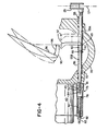
- Figs. 3 through 7 constitute sequential views, and illustrate the operation of this invention in the beta or direct feedback mode, when the propeller is under control of the beta valve 20.
- Fig. 4 shows the movement of the yoke arm 52 from the phantom position where it was under control of the governor to a full line position where the arms 52, at their extremities, have just picked up the beta rods at a blade angle somewhat slightly higher than the flight idle angle setting.
- the beta rods and collar 25 are shown in the home position as represented by the datum line 57.
- the angle 95 illustrating a typical flight condition, may be 35°, while an angle 96 may be 18-1/2°. At this point, there has been no movement of the beta feedback rods 55 or the collar 25.
- Fig. 5 shows how the continued movement of the arm 52 picks up and moves a beta rod 55 to a predetermined flight idle range which may be some 4-1/2° less than the angle 96 of Fig. 4, for example 14°, as represented by the angle 98.
- a predetermined flight idle range which may be some 4-1/2° less than the angle 96 of Fig. 4, for example 14°, as represented by the angle 98.
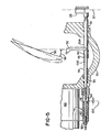
- Figs. 6 and 7 depict the position of the parts when the pilot selects a ground idle position, such as following the landing roll and during taxing operations.
- the initial movement of the power levers through the cam box 30 causes a slight movement of the push/pull rod 22 and the lever 23 to open the beta valve 20.
- the blades 36 now move to the full line position as shown in Fig. 6. This movement may be only about 2°, but sufficient to close the gap 100 and to bring the ends 84 of the rods 55 into contact with their respective stops 78. However, this movement is not enough to reclose the beta valve, and the piston 37 continues to move to the left under the influence of hydraulic pressure through the valve 20.
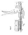
- Fig. 7 further illustrates the position of the parts in the event reverse pitch is called for by the pilot.
- the rods 55 are caused to move through a further distance 104 indicated by the displaced movement of the stops 78.
- a movable stop means in the form of sleeves on the rods 55, which may move through a finite distance only after the beta rods 55 have come into engagement with the stop 78, provides for the continued movement of the propeller blades 36 automatically to a lower blade angle, to assure a ground operating condition which has low thrust and permits sufficiently high rpm, as previously noted.
- the gap 100 as well as the home position of the stop 78 are selected so as to assure that the automatic shift to a lower pitch range does not occur at the flight idle angle position, but only occurs after the power levers have been moved into the ground idle range.
- the beta valve is again opened slightly and the initial movement of the blades into engagement with the sleeves causes the sleeves to bring the beta rods 55 through the distance represented by the space 100, thus temporarily arresting the movement of the beta rods accompanied by sliding movement of the sleeves 60 on the rods 55 until the same have come into engagement with the pins 66, at which time the rods 55 are again picked up and permitted to move with the blades until the beta valve is reclosed.
- the movement available to the pilot by moving the power levers from the flight idle position into the ground idle range, is accompanied by a substantially larger and smooth transitional movement of the blades from a rather substantial flight idle angle to a very low blade angle for ground idle operation.
- the sleeves 60 define movable stop means or lost motion connections coupling the yoke 50 to the beta feedback rods 55 and collar 25.
- This movable stop means comes into operation only during movement of the power lever from the flight idle to ground idle position, and permits the blades 36 to move to a lower blade angle by providing for a range of movement of the blades in which the beta rods are not moved.
- the entire beta shift mechanism is integral with the propeller blade change mechanism and does not require any external solenoid or other device for the purpose of shifting the beta valve, to achieve a low blade pitch angle for ground idle positions.
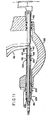
- FIG. 8 through 12 An alternative preferred embodiment of the invention is illustrated in Figs. 8 through 12, in which like parts have been labeled with like reference numerals from the preceding embodiment, plus 100.
- the embodiment of Figs. 8 through 12 differ primarily from the preceding embodiment in that the movable stop 78, formerly positioned externally of the hub, in this preferred embodiment, positioned internally of the hub in the form of a spring biased collar arrangement formed concentric to and slidably mounted on the beta feedback rods themselves.
- the hub 135 is shown as slidably mounting one of the beta feedback rods 155 on inset bushings 200 and 202.
- the identical blade yoke 50 and pick-up arms 52 are employed as in the preceding embodiment.
- the movable sleeves 160 are slidably mounted on the rods 155 and are similarly formed with a collar or shoulder 165 for engaging the forked ends of one of the arms 52.
- the sleeve 160 operates in the same manner as that previously described in connection with the sleeve 60, and is normally biased into its seated position by a spring 162.
- a snap-ring 166 is received in a groove 167 on the rod 155, and forms a seat for the spring 162.
- the ring 66 also forms a seat, on its opposite side, for a second sliding collar 220.
- a second sliding collar 220 is biased to its seated position by a spring set 156 corresponding to spring 56.
- the second sleeve 220 operates to define the gap 100.
- This gap is now established between the inner end of the sleeve 220 and the flanged end 225 of a movable tubular stop 178 corresponding in function to the stop 78 of the preceding embodiment.
- the movable stop 178 is formed as a sleeve in telescopic relation to the rod 155 and extending inwardly into the interior of the hub 135 through the bushing 202.
- the position of the annular head or flange 225 of the sleeve 178 may be set by the nut 182 on the exposed threaded end 226.
- a compression spring 180 corresponding generally to the spring 80, maintains the stop member 178 in a seated position with the nut 182 resting on an external spacer sleeve 225.
- Fig. 9 the arm 52 has caused the beta rod to move to the left from its home position to and take up most of the gap 100, followed by compression of the beta rod return springs 156.
- Fig. 10 the sleeve 220 has now seated on the head 225, corresponding to the position of the parts of the first embodiment as shown in Fig. 6 where the end 84 had engaged the head 78.
- Fig. 11 This condition is shown in Fig. 11 and results in the blades being shifted to a lower pitch position in the same manner as previously described in connection with the movement of the sleeve 60 from its seated to its moved position with the compression of the spring 62.
- Figs. 8 through 12 One of the principal advantages of the embodiment of the invention is illustrated in Figs. 8 through 12 is the fact that the moving stop mechanism is now containted entirely within the interior of the propeller hub where it is physically protected as well as lubricated.
Landscapes
- Engineering & Computer Science (AREA)
- Aviation & Aerospace Engineering (AREA)
- Structures Of Non-Positive Displacement Pumps (AREA)
- Transmission Devices (AREA)
Abstract
Description
- This invention relates to controllable pitch aircraft propellers and more particularly to such propellers which are adapted to be operated with free turbine engines having a beta pitch control mechanism, such as the Pratt & Whitney PT 6A engine series, for example. More particularly, the invention relates to reversible pitch turbo-propeller which is capable of automatically providing a blade shift to a lower pitch angle, upon command of the pilot during ground operations, for the purpose of maintaining the rpm of the turbine and the thrust of the propeller within acceptable limits and for assuring that the propeller does not operate in the reactionless mode.
- The propeller control system to which the present invention is applied is basically the system as shown in United States patents Nos. 3,249,159 issued May 3, 1966 to Biermann and 3,446,289 issued May 27, 1969 to Morris, Jr., in which the blade position is transmitted to a valve (a beta valve) through a mechanical feedback arrangement carried on the propeller. While the control system illustrated herein is applied to an external feedback propeller, of the general type shown in Biermann Patent No. 3,249,159 as noted above, it should be understood that the invention is not limited to this particular concept and may be applied, for example, to a propeller with internal feedback to a beta rod such as shown in Biermann U. S. Patent No. 2,986,222 issued May 30, 1961 or Biermann U. S. Patent No. 3,380,535, issued April 30, 1968.
- During the approach conditions, if the pilot selects an approach or flight idle position, such as during flare out and touchdown, the propeller blades are normally maintained by the system at a minimum positive blade angle. This angle has been selected to provide relatively low thrust or drag, taking into account the approach speed of the aircraft, and the minimum gas generator speed required to sustain the operation of the gas turbine. However, once the aircraft has landed and its landing speed has been largely dissipated, the propeller blade angle is often high enough to cause the propeller rotation speed to be lowered into the speed range of a reactionless mode. This reduction in propeller rpm during taxi operation is due to the nature of the free turbine engine in that the propeller and free power turbine speed is a function of blade angle and gas generator speed. However, it is not practical to permit the propeller speed to drop below a minimum level at which a reactionless mode may be encountered.
- The term reactionless mode describes a resonance vibration condition which can affect propellers having four or more blades, during ground operation. Generally, the reactionless mode condition is more likely to occur during ground operations in crosswinds or in quartering tailwinds, and during times that the propeller speed has dropped into a critical range. Each propeller design having four or more blades is characterized by known or predictable conditions at which the reactionless mode may be encountered. Since the reactionless mode results in high blade and hub stresses, without producing any net load to the engine flange, it is a condition to be avoided whenever possible. One way of avoiding this condition is to provide a system which is capable of decreasing the blade angle, at or following landing or rollout, either automatically or at the command of the pilot, to a point where the blade will continue to be driven by the turbine at an rpm safely above that range in which the reactionless mode may occur. For example, a propeller may be physically designed to encounter reactionless mode conditions in the range of 700 to 1,000 rpm, and the control system may be designed to provide a power setting and/or blade setting which assures that the propeller speed does not fall below 1,050 rpm during ground operations. However, simply adding fuel to the turbine to maintain such propeller speeds, without further descreasing the blade angle from the minimum approach configuration, commonly results in substantial excess thrust, thereby causing problems for the pilot in taxiing and the like.
- In an initial attempt to deal with this condition, aircraft engine manufacturers have added a selectable position to the power levers, namely that of ground idle. The control quadrant is provided with a stop or gate arrangement which normally intercepts the power levers at the flight idle minimum position. However, the pilot has the means of moving the power levers in such a way as to bypass this stop or gate into a ground idle range, usually by grasping and lifting the levers over the gate. During this movement, a mechanical cam is brought into operation which physically moves the beta valve in such a direction as to cause the propellers to decrease pitch by a small amount, such as about 4°. At the same time, a connection is made by the cam to the fuel control arm of the turbine fuel control unit which may cause the fuel control unit on the engine to deliver the specified amount of turbine fuel to the engine to assure that it maintains its minimum operating speed during ground operations.
- Airframe or propeller manufacturers have found that the propeller idle cam arrangement does not by itself move the beta valve sufficiently to cause a sufficient decrease in blade angle. This is due to the fact that the amount of movement available between flight idle and ground idle positions, the amount of cam surface available, and the forces required to move the cam physically restrict the same to about a maximum of 8° movement of pitch angle. Accordingly, both engine and airframe manufacturers have devised additional arrangements for imparting further blade movement to lower pitch settings following landing.
- One arrangement which has come-into relatively wide use is that employed by the Beech Aircraft Company in its King Air models, consisting of a squat switch operated electric solenoid. The switch may be directly operated by the pilot or it may be indirectly operated by sensing a power lever position in the ground idle range or it may be automatically operated by means of a connection to the landing gear and be operated when the landing gear has contacted the ground and sufficient weight has been transferred to the wheels. In any case, a squat switch actuates an electric solenoid coupled to the beta valve and effects a predetermined additional shift to this valve, independent of the movement of the power levers into the ground idle range, causing the propeller blades to move to a lower and acceptable pitch angle for ground operation, as compared to the higher approach angle.
- An additional system has been designed by Pratt & Whitney which is pneumatically operated by bleed air from the compressor, to operate a pneumatic piston which, like the Beech system, is mechanically connected to reopen and move the beta valve through a _finite distance. The application of bleed air to the piston is again either controlled or operated by a squat switch on the landing gear or operated by a pilot command switch.
- In either the Beech or the Pratt & Whitney systems, the means by which the blade angle is reduced consists of an external actuator which is connected to move the beta valve and thus reopen the same to cause additional movement of the propeller pitch changing mechanism to a lower pitch angle until the movement is transferred back by the pitch change mechanical feedback mechanism to the beta valve, at which point the valve is reclosed. In both systems, the blade angle is reduced to raise propeller speed out of the range of reactionless mode while leaving the gas generator at its minimum sustaining power level or speed, as outlined above.
- Since the existing systems are operated generally external to the propeller, and require a separate source of power for operation, such as bleed air and/or electric power, there exists a need for a completely self-contained beta shift mechanism operated within the propeller pitch change mechanism itself.
- As previously noted, the invention is directed to a controllable pitch propeller or propeller system, which may be a reversible pitch system, which incorporates a blade angle change mechanism known as a beta control, and in which the pitch angle position of the propeller may be placed under the direct control of the pilot through a mechanical feedback arrangement to the beta valve. The improvement consists of a mechanical arrangement on the propeller through which lower pitch angles may be available for ground operation, to maintain the propeller rpm at a desirable minimum speed. The mechanism provides smooth transition to such lower pitch angles when power lever is moved by the pilot into the range of ground idle position. Concurrently with the shifting to the lower blade angle, the lower idle N g fuel setting may be selected, to prevent the propeller speed from going much above a desired minimum established for ground operation.
- Conventionally, the propeller mechanism itself is provided with mechanical feedback in the form of rods or the like, through which=the blade angle position is fed back to the beta valve. The invention includes an arrangement by means of which the blades, under the influence of the hydraulic piston, are permitted to move through an additional change in blade angle without effecting a corresponding change in position of the feedback rods. This is accomplished in the preferred embodiments by one or more spring biased movable stops in the form of sliding collars or the like, which permits the blade yoke which couples the beta feedback rods to the propeller blades, to shift through a certain and predetermined distance, corresponding to a predetermined decrease in pitch angle, without effecting corresponding movement of the rods, and thereafter to pick up the movement of the rods for lower pitch positions, or negative pitch positions such as during reverse thrust operations.
- The apparatus forms a movable spring-loaded connection in association with the propeller beta feedback rods which provides for movement of the blades automatically to a lower pitch position upon a minimum higher pitch position. The spring-loaded connection thereafter picks up the beta feedback rods after the blades have moved through a predetermined angle. Thus, the pilot may select a flight idle position of, for example 17°, in the beta control range of the system. Upon landing, the pilot may then select a ground idle position by movement of his power levers out of a gate to a more rearward position. This operates to move the beta valve sufficiently so that the blade yoke picks up or engages the movable stop or sleeve arrangements on the beta rod. The movable sleeves permit the yoke to move through a predetermined extent, corresponding to a further decrease in pitch of from 5-8° for example, without effecting further movement of the beta feedback rods. Thereafter, the beta feedback rods are again picked up and are caused to follow the position of the blades. The latter action causes the beta valve to close as a hydraulic low pitch stop. The pilot may also select a reverse thrust position, conventionally, if desired.
- More broadly, the movable spring-loaded connections may be considered lost motion connections which come into operation only upon the propeller blades arriving at a particular minimum pitch condition, under control of the beta valve, which connections temporarily interrupt the mechanical feedback to the beta valve, so that the blades continue to be moved through a finite angle until the feedback mechanism is again picked up by the blade yoke. The extent of movement may be determined by controlling the amount of free movement of the blade yokes with respect to the position feedback mechanism, such as by controlling the length of movable sleeves between spaced fixed stop members, and the position at which this automatic shifting of the blades to a lower pitch position occurs may be controlled by suitably positioning the movable stops in relation to the blade yoke and in relation to the flight idle position. In accordance with this invention, the lost motion connection will not come into operation at blade angles at or above the flight idle position and not until specifically selected by the pilot.
- Two embodiments of the invention are shown and described. A first embodiment incorporates a portion of the stop mechanism located exteriorly of the propeller hub while a second embodiment incorporates the entire mechanism within the interior of the propeller hub.
- It is accordingly an important object of this invention to provide apparatus, associated with the propeller itself, by means of which lower blade angles may be automatically selected for ground operation.
- A still further object is the provision of a propeller, particularly adapted or suited for use with turbine engines, which includes blade angle shift mechanisms operable upon the pilot selecting a ground idle position with his power levers, to bring the blades into nearly flat or desired low pitch position, to maintain minimum blade rpm.
- A still further object of the invention is the provision of a propeller system, as outlined above, which automatically selects lower blade angles for ground operation conditions, employing a selectively movable stop mechanism on the propeller for temporarily interrupting the movement of the beta feedback rods.
- A further object of the invention is the provision of a propeller mechanism with a movable low pitch position stop mechanism which permits the blades to be carried to lower pitch angle positions during ground idle operations.
- These and other objects and advantages of the invention will be apparent from the following description, the accompanying drawings, and the appended claims.
- In order that the invention may be more readily understood, referene will not be mae to the accompanying drawings, in which:
- Fig. 1 is a partially schematic system diagram of a control system for a reversing aircraft propeller, according to this invention;
- Fig. 2 is a schematic sectional view through the propeller hub, illustrating the principles of operation of the propeller with the parts being shown in a typical flight position under governor control;
- Figs. 3 through 7 are enlarged fragmentary sections through the propeller hub showing one of the beta feedback rods with the position of the propeller blade shown;
- Fig. 3 shows the position of the parts in a typical governing flight configuration;
- Fig. 4 shows the movement of the propeller blade yoke into initiation of the beta feedback position;
- Fig. 5 shows the movement of the yoke and beta feedback rod to the flight idle range;
- Fig. 6 shows the initial movement of the blade yoke and beta feedback rod to a ground idle range;
- Fig. 7 shows the completed movement of the sleeve on the beta feedback rod permitting movement of the blade yokes to a full ground idle range;
- Figs. 8 through 12 are enlarged fragmentary sections through the propeller hub, similar to Figs. 3 through 7, showing another embodiment of the invention, in which the moving stop members are located entirely within the propeller hub;
- Fig. 8 shows the position of the parts under governor control;
- Fig. 9 is similar to Fig. 4, and shows the movement of the propeller blade yoke at the initiation of beta control;
- Fig. 10 shows the position of the parts in the flight idle range, similar to the position of the parts in Fig. 5;
- Fig. 11 shows the further movement of the parts to the ground idle range, similar to the position shown in Fig. 7 for the first embodiment; and
- Fig. 12 shows the position of the parts during further movement, such as to a reverse thrust position, as for example shown in broken line form in Fig. 7.
- Referring to Fig. 1, a controllable, reversible pitch aircraft propeller embodying this invention is illustrated generally at 10. The
propeller 10 to which the present invention is applied uses hydraulic pressure to move the blades to a low pitch position, and employs a spring and counterweights to carry the blades to higher pitch positions and to the feathered position. - The
propeller 10 is controlled by a hydraulic control system which includes a source of oil under pressure. The oil is applied to the propeller through agovernor assembly 12, under normal flight conditions, in accordance with the pitch of agovernor speed lever 14. A conventional propelleroverspeed governor 15 is connected to dump fluid from the propeller to the sump, to permit the propeller to go to higher pitch settings in the event of overspeed conditions. Thefuel governor 18 controls the amount of fuel to a turbine engine, not shown, by means of afuel control lever 19. - The
governor assembly 12 includes abeta valve 20, also connected to apply hydraulic fluid to thepropeller 10 through the internal passageways in thegovernor assembly 12. Thebeta valve 20 may be initially positioned by a push/pull control rod 22 operating through a floatinglever 23. The opposite end of the floating reversinglever 23 is connected to a slider brush or block 24 which runs in a groove in a betaposition feedback collar 25 carried on thepropeller 10. The pilot's power levers (notshown) are connected to operate the push/pull control rod 22 through a control beta cam box 30. - The
propeller 10 has ahub 35 in which a plurality ofpropeller blades 36 are mounted, typically three or four. The position of the propeller blades is controlled by afluid motor piston 37 opposed by thespring 38 andconventional counterweights 39. Applying hydraulic fluid to the propeller causes theblades 36 to move to a lower pitch position, and to reverse pitch positions, while thespring 38 andcounterweights 39 carry theblades 36 toward the high pitch and to the feather positions. - In most flight operations, the pitch of the
propeller blades 36 is controlled by the fly weight governor contained within thegovernor assembly 12. The governor itself is of conventional construction including the usual flyweights operating against an internal speeder spring. The speeder spring is biased by thespeed adjusting lever 14, controlled by the pilot. However, in the beta range, during low and reverse pitch conditions, and when the governor is operating too slowly to be a governing factor, the position of the propeller may be directly controlled by the pilot by movement of therod 22 through the cam box 30, through the movement of the pilot's power levers. This results in a shifting of the spool of thebeta valve 20. Pulling the push/pull control rod 22 to the left, as viewed in Fig. 1, causes an opening movement of thebeta valve 20, with concurrent application of hydraulic fluid to thepiston 37. This causes the piston to bring the propeller blades to a lower pitch position, accompanied by concurrent moving movement of thecollar 25 and the floatinglever 23 forwardly in such a manner as to reclose thebeta valve 20. The control beta cam box is also connected to thefuel lever 19 through a push/pull connecting rod 34, to control the turbine fuel governor, so as to limit propeller rpm in the ground and reverse positions, as well as to schedule fuel for high powered forward flight. - Further details of the propeller itself and the servo piston for positioning the blades may be seen in Fig. 2. The
piston 37 is slidably mounted in acylinder dome 40 for movement under the influence of hydraulic pressure againstcounterweights 39 and against aspring 38. Hydraulic operating fluid is fed through an internal hollow piston tube orrod 45. The movement of thepiston 37 is translated to theblades 36 through connectinglinks 48, one of which is shown in Fig. 2. Thelinks 48 are connected to the blade root ends near the trailing edge of each blade. - The hub of the propeller contains an internal spider or
yoke 50 mounted on thetube 45. Theyoke 50 has as many radially extendingarms 52 as there are propeller blades. Thus, in the case of a four-bladed propeller theyoke 50 will have fourindividual arms 52, one of which is shown in Fig. 2. Each yoke arm is forked or slotted at its outer extremity so that each partially circles and forms a close fit with onebeta feedback rod 55. There is onebeta feedback rod 55 for each propeller blade, and each rod is mounted and supported in plain bearings at the front and aft ends of thepropeller hub 35, and biased by return springs 56 to ahome position 57 as shown in Figs. 2 and 3. The aft end of eachrod 55 is connected to theannular feedback collar 25 which accordingly follows the position of therods 55. This position is translated through the carbon brush or block 24 to thelever 23, and to thebeta valve 20. - In'the governor mode, oil is metered to and from the
propeller 10 by the governor pilot valve as positioned by the internal fly weights (not shown) for increasing and decreasing the blade angle as required when the propeller speed control setting at thelever 14 is altered or for increasing and decreasing pitch to control and stabilize the propeller speed with varying power conditions or flight with a fixed setting of thelever 14. During this movement, theyoke 50 and theindividual arms 52 move in translation along the surfaces of theindividual rods 55, without imparting any movement to these rods. A typical flight position of theyoke 50 and blades is illustrated in Figs. 2 and 3. In lower pitch positions, in which the propeller blades are under beta control, the position of theblades 36 is fed back by thearms 52 of theyoke 50 to thefeedback rods 55. - The pilot may select the beta mode operation for ground reversing or taxi operations through the aircraft-engine mechanical linkage which repositions the propeller reversing lever and the beta valve to provide access for high oil pressure to reach the propeller piston and thus to move the blade from a low pitch position to or toward a reverse position. As previously noted, the
yoke 50 translates the motion of theinternal piston rod 45 to thefeedback collar 25 which supports thestationary carbon block 24. - The general configuration and operation of the propeller control system, described above, is similar to that shown and described in the above-identified patents of Biermann and Morris, Jr. However, in these patent disclosures, there is no provision for an expanded range of propeller movement, during beta control, without effecting concurrent movement of the feedback rods. Therefore, once the propeller was under control of the pilot, in the feedback mode, the position of the blades was more or less directly proportional to the position of the beta valve spool. Thus, in order to achieve a further reduction in blade angle from the flight idle position, to achieve a lower blade angle for ground operating conditions, it was necessary to effect mechanically a further movement of the beta valve to achieve such decreased blade angle, over and above that provided to the pilot through the cam box 30 by the movement of the power levers.
- This invention includes means providing for a predetermined movement of the
blades 36, during beta operation, without incurring a corresponding movement of the feedback mechanism. This function is operative upon the pilot selecting a position in the ground operating range, below flight idle position of the cam box 30, with the pilot's power levers, and automatically decreases the blade angle by a predetermined extent, which may be, for example, between 4° and 10°. For this purpose, thebeta feedback rods 55, which have heretofore been provided with a fixed stop to pick up theyoke arms 52, as shown in the previously identified prior art patents, are now provided with movable pickup stops. The movable stops may take the form ofsleeves 60, slidably received onrods 55 and normally biased against a shoulder orenlarged diameter portion 55A by first compression springs 62. Eachsleeve 60 carries anannular pickup ring 65 which is proportioned to be engaged by the forked end of anarm 52. Eachspring 62 is held under compression by apin 66 or the like carried in a suitable hole through thesmaller diameter portion 55B of therod 55. A snap ring in a groove on the rod could also be used. The conventional rodreturn coil spring 56 is received over therod 55 between a recessedportion 70 of the hub and thepin 66. - The
sleeves 60 are held by thesprings 62 in a normally seated position as shown in Fig. 3 against theshoulders 55A, and are movable on the rods to a moved position by compression of thesprings 62. It should be noted that the force required to compress eachspring 62 is greater than the force exerted by thereturn spring 56, so that when the forked end of thearm 52 of the yoke engages thepickup ring 65 on thesleeve 60, therod 55 will be moved to the left as viewed in Figs. 3-7. It should also be noted that thesleeves 60 have a defined and limited range of movement with respect to therods 55, which range is defined by the space orgap 71 between the ends of the sleeve and thepin 66. - The invention further includes adjustable and movable
rod stop members 75, one for eachrod 55. Thestop members 75 are positioned to interrupt temporarily the movement of thefeedback rods 55. In the embodiment of Figs. 3-7, thestop 75 is contained in atubular housing 79 which has an inner end received over and fixed to anannular boss 81 formed on the hub, in generally coaxial relation with therod 55. - Each movable stop member includes an internal plunger-shaped
stop 78 which is spring-biased by aspring 80 to a normally seated position, as shown in Fig. 3, the exact position of which is defined by anut 82 threaded on anexposed end 83 of the stop. An exposed threadedend 84 of therod 55 extends through the hub and into the interior of thehousing 79, and carries a threaded adjustingnut 85 on the end thereof, to define the normal seated position of thebeta feedback rod 55. It should be noted here that the force required to compress thestop spring 80 is greater than the force required to compress thespring 62 of thesleeve 60 and is also, therefore, greater than that required to compress thespring 66. - Figs. 3 through 7 constitute sequential views, and illustrate the operation of this invention in the beta or direct feedback mode, when the propeller is under control of the
beta valve 20. - Fig. 4 shows the movement of the
yoke arm 52 from the phantom position where it was under control of the governor to a full line position where thearms 52, at their extremities, have just picked up the beta rods at a blade angle somewhat slightly higher than the flight idle angle setting. The beta rods andcollar 25 are shown in the home position as represented by thedatum line 57. For example, theangle 95, illustrating a typical flight condition, may be 35°, while anangle 96 may be 18-1/2°. At this point, there has been no movement of thebeta feedback rods 55 or thecollar 25. - The next sequential view, Fig. 5, shows how the continued movement of the
arm 52 picks up and moves abeta rod 55 to a predetermined flight idle range which may be some 4-1/2° less than theangle 96 of Fig. 4, for example 14°, as represented by theangle 98. When the bifurcated end of thearm 52 contacts the annular pick-upring 65 of thesleeve 60, therod 55 is first moved to the left. At this point, asmall gap 100 is formed between the threadedadjustable end 84 of therod 55 and thestop 78. - Figs. 6 and 7 depict the position of the parts when the pilot selects a ground idle position, such as following the landing roll and during taxing operations. The initial movement of the power levers through the cam box 30 causes a slight movement of the push/
pull rod 22 and thelever 23 to open thebeta valve 20. Theblades 36 now move to the full line position as shown in Fig. 6. This movement may be only about 2°, but sufficient to close thegap 100 and to bring theends 84 of therods 55 into contact with their respective stops 78. However, this movement is not enough to reclose the beta valve, and thepiston 37 continues to move to the left under the influence of hydraulic pressure through thevalve 20. Since therods 55 have come into contact withstops 78, and since the sleeve springs 62 have a lower compressive force than the stop springs 80, theyoke 50 and associatedarms 52 continue to move by causing thesleeves 60 to move relative to therods 55 by compressing thesprings 62. This condition is illustrated in Fig. 7. The total movement as permitted by thesleeves 60 is through thegap 71 and permits the blades to move to a ground idle position through some additional 6°. When thesleeves 60 have moved into contact.with theirrespective stops 66, thefeedback rods 55 are again picked up and moved with thearms 52 now accompanied by movement of thestops 78 against thesprings 80. The beta valve is now closed, and the blades have been shifted a substantial distance to a very low blade angle. In bringing the blades to a higher pitch position the sequence is reversed. - Fig. 7 further illustrates the position of the parts in the event reverse pitch is called for by the pilot. The
rods 55 are caused to move through afurther distance 104 indicated by the displaced movement of thestops 78. - The arrangement of a movable stop means in the form of sleeves on the
rods 55, which may move through a finite distance only after thebeta rods 55 have come into engagement with thestop 78, provides for the continued movement of thepropeller blades 36 automatically to a lower blade angle, to assure a ground operating condition which has low thrust and permits sufficiently high rpm, as previously noted. - The
gap 100 as well as the home position of thestop 78 are selected so as to assure that the automatic shift to a lower pitch range does not occur at the flight idle angle position, but only occurs after the power levers have been moved into the ground idle range. Thus, when a ground idle position of the power levers is selected, the beta valve is again opened slightly and the initial movement of the blades into engagement with the sleeves causes the sleeves to bring thebeta rods 55 through the distance represented by thespace 100, thus temporarily arresting the movement of the beta rods accompanied by sliding movement of thesleeves 60 on therods 55 until the same have come into engagement with thepins 66, at which time therods 55 are again picked up and permitted to move with the blades until the beta valve is reclosed. The movement available to the pilot, by moving the power levers from the flight idle position into the ground idle range, is accompanied by a substantially larger and smooth transitional movement of the blades from a rather substantial flight idle angle to a very low blade angle for ground idle operation. - In summary, the
sleeves 60 define movable stop means or lost motion connections coupling theyoke 50 to thebeta feedback rods 55 andcollar 25. This movable stop means comes into operation only during movement of the power lever from the flight idle to ground idle position, and permits theblades 36 to move to a lower blade angle by providing for a range of movement of the blades in which the beta rods are not moved. The entire beta shift mechanism is integral with the propeller blade change mechanism and does not require any external solenoid or other device for the purpose of shifting the beta valve, to achieve a low blade pitch angle for ground idle positions. - An alternative preferred embodiment of the invention is illustrated in Figs. 8 through 12, in which like parts have been labeled with like reference numerals from the preceding embodiment, plus 100. The embodiment of Figs. 8 through 12 differ primarily from the preceding embodiment in that the
movable stop 78, formerly positioned externally of the hub, in this preferred embodiment, positioned internally of the hub in the form of a spring biased collar arrangement formed concentric to and slidably mounted on the beta feedback rods themselves. Thehub 135 is shown as slidably mounting one of thebeta feedback rods 155 oninset bushings identical blade yoke 50 and pick-uparms 52 are employed as in the preceding embodiment. - The
movable sleeves 160, similar to thesleeve 60, are slidably mounted on therods 155 and are similarly formed with a collar orshoulder 165 for engaging the forked ends of one of thearms 52. In this embodiment, thesleeve 160 operates in the same manner as that previously described in connection with thesleeve 60, and is normally biased into its seated position by aspring 162. Instead of thepin 66, a snap-ring 166 is received in a groove 167 on therod 155, and forms a seat for thespring 162. Thering 66 also forms a seat, on its opposite side, for a second slidingcollar 220. A second slidingcollar 220 is biased to its seated position by aspring set 156 corresponding tospring 56. There are no parts in the preceding embodiment which correspond directly to thesecond sleeve 220, except to note that thesecond sleeve 220 operates to define thegap 100. This gap is now established between the inner end of thesleeve 220 and theflanged end 225 of a movable tubular stop 178 corresponding in function to thestop 78 of the preceding embodiment. In this instance, the movable stop 178 is formed as a sleeve in telescopic relation to therod 155 and extending inwardly into the interior of thehub 135 through thebushing 202. The position of the annular head orflange 225 of the sleeve 178 may be set by thenut 182 on the exposed threadedend 226. A compression spring 180, corresponding generally to thespring 80, maintains the stop member 178 in a seated position with thenut 182 resting on anexternal spacer sleeve 225. - The sequence of operation can best be understood by referrring to the respective Figs. 9 through 12. In Fig. 9, the
arm 52 has caused the beta rod to move to the left from its home position to and take up most of thegap 100, followed by compression of the beta rod return springs 156. In Fig. 10, thesleeve 220 has now seated on thehead 225, corresponding to the position of the parts of the first embodiment as shown in Fig. 6 where theend 84 had engaged thehead 78. Continued movement of thearms 52 is now accompanied by sliding movement of thesleeve 165 on therod 155 by compressing thespring 162. This condition is shown in Fig. 11 and results in the blades being shifted to a lower pitch position in the same manner as previously described in connection with the movement of thesleeve 60 from its seated to its moved position with the compression of thespring 62. - Continued movement now picks up the beta rod since there are no further gaps between either the
sleeve 160 or the sleeve 222 and thehead 225 of the movable stop 178. Actually, this movement is picked up by the end of thesleeve 160 contacting thesnap ring 166. Such movement continues to a point where the beta valve is mechanically reclosed, as illustrated in Fig. 12 where thenut 182 has been lifted off of thespacer 225 and is moved through a distance 204 corresponding to thedistance 104 of the preceding embodiment. It will be noted that the beta rod return springs 156 require the least force to compress, followed by thesprings 162, with the spring set 180 requiring the greatest force to compress, to set up the required sequence of operation. - One of the principal advantages of the embodiment of the invention is illustrated in Figs. 8 through 12 is the fact that the moving stop mechanism is now containted entirely within the interior of the propeller hub where it is physically protected as well as lubricated.
- While the forms of apparatus herein described constitute preferred embodiments of this invention, it is to be understood that the invention is not limited to these precise forms of apparatus, and that changes may be made therein without departing from the scope of the invention which is defined in the appended claims.
Claims (5)
Applications Claiming Priority (2)
| Application Number | Priority Date | Filing Date | Title |
|---|---|---|---|
| US06/729,438 US4648798A (en) | 1985-05-01 | 1985-05-01 | Controllable pitch aircraft propeller |
| US729438 | 1985-05-01 |
Publications (3)
| Publication Number | Publication Date |
|---|---|
| EP0200337A2 true EP0200337A2 (en) | 1986-11-05 |
| EP0200337A3 EP0200337A3 (en) | 1987-10-14 |
| EP0200337B1 EP0200337B1 (en) | 1990-09-26 |
Family
ID=24931027
Family Applications (1)
| Application Number | Title | Priority Date | Filing Date |
|---|---|---|---|
| EP86302082A Expired EP0200337B1 (en) | 1985-05-01 | 1986-03-20 | Controllable pitch aircraft propeller |
Country Status (3)
| Country | Link |
|---|---|
| US (1) | US4648798A (en) |
| EP (1) | EP0200337B1 (en) |
| DE (1) | DE3674454D1 (en) |
Cited By (4)
| Publication number | Priority date | Publication date | Assignee | Title |
|---|---|---|---|---|
| RU2129075C1 (en) * | 1997-08-28 | 1999-04-20 | Акционерное общество "Мотор Сiч" | Reversible propeller |
| WO2014035502A3 (en) * | 2012-05-30 | 2014-06-26 | Woodward, Inc. | Electrohydraulic propeller governor |
| EP2774842A1 (en) * | 2013-01-07 | 2014-09-10 | Hamilton Sundstrand Corporation | Propeller blade with relatively movable counterweight |
| WO2019060214A1 (en) * | 2017-09-25 | 2019-03-28 | Woodward, Inc. | Propeller control unit |
Families Citing this family (14)
| Publication number | Priority date | Publication date | Assignee | Title |
|---|---|---|---|---|
| US4872811A (en) * | 1987-08-03 | 1989-10-10 | Bird-Johnson Company | Inboard servo for marine controllable pitch propellers |
| US4909709A (en) * | 1988-06-22 | 1990-03-20 | Raisbeck James D | Throttle/propeller mixer cam |
| US5061153A (en) * | 1988-11-21 | 1991-10-29 | Hartzell Propeller Inc. | Aircraft propeller assembly with blade pitch reset for ground idle |
| US4904157A (en) * | 1988-11-21 | 1990-02-27 | Hartzell Propeller Inc. | Aircraft propeller assembly with blade pitch reset for ground idle |
| US4958289A (en) * | 1988-12-14 | 1990-09-18 | General Electric Company | Aircraft propeller speed control |
| US6213713B1 (en) | 1998-12-31 | 2001-04-10 | United Technologies Corporation | Apparatus for indicating pitch angle of a propeller blade |
| US7758310B2 (en) * | 2007-01-15 | 2010-07-20 | Sikorsky Aircraft Corporation | Translational thrust system for a rotary wing aircraft |
| JP2011521153A (en) * | 2008-05-13 | 2011-07-21 | ローテイティング コンポジット テクノロジーズ, エルエルシー | System for fan blade retention and variable pitch |
| US8133027B2 (en) * | 2008-07-14 | 2012-03-13 | Hamilton Sundstrand Corporation | Integrated actuator for a propeller system |
| EP3434584B1 (en) * | 2017-07-28 | 2021-06-02 | Ge Avio S.r.l. | System and method for determining minimum pitch and minimum gas generator idle condition |
| CN109677588A (en) * | 2018-12-11 | 2019-04-26 | 中国航空工业集团公司西安航空计算技术研究所 | A kind of propeller and Match control method, device and storage medium |
| US11414175B2 (en) * | 2019-04-01 | 2022-08-16 | Pratt & Whitney Canada Corp. | Method and system for operating an aircraft powerplant |
| HU231244B1 (en) * | 2020-01-10 | 2022-05-28 | László Kruppa | Improved propeller for aircraft |
| US11794913B2 (en) | 2020-10-20 | 2023-10-24 | The Boeing Company | Integrated electric propulsion unit |
Family Cites Families (16)
| Publication number | Priority date | Publication date | Assignee | Title |
|---|---|---|---|---|
| US2704583A (en) * | 1955-03-22 | Adjustable hydraulic reverse stop | ||
| US2959156A (en) * | 1956-08-03 | 1960-11-08 | Sarl Ratier Aviat Marine | Hydraulic servo-device for controlling linearly or rotatably movable members, with indication of the position thereof |
| US2916094A (en) * | 1956-12-11 | 1959-12-08 | Gen Motors Corp | Propeller control system |
| US2986222A (en) * | 1959-07-24 | 1961-05-30 | Hartzell Propeller Inc | Adjustable pitch propeller |
| US3057140A (en) * | 1961-06-23 | 1962-10-09 | Ridenour Charles Amos | Power-driven lawn mower with pivotal frame construction |
| GB1021544A (en) * | 1961-08-12 | 1966-03-02 | Dehavilland Aircraft | Improved variable pitch propeller control system |
| US3167131A (en) * | 1963-09-03 | 1965-01-26 | Cessna Aircraft Co | Controllable pitch propeller having low pitch stop |
| US3249159A (en) * | 1965-01-06 | 1966-05-03 | Hartzell Propeller Inc | Propeller control system |
| US3261405A (en) * | 1965-02-09 | 1966-07-19 | Fairchild Hiller Corp | Aircraft power control apparatus |
| US3380535A (en) * | 1965-12-27 | 1968-04-30 | Hartzell Propeller Inc | Constant speed and reversible aircraft propeller |
| US3389641A (en) * | 1966-10-24 | 1968-06-25 | United Aircraft Corp | Hydraulic control mechanism with hydraulic delayed reset |
| US3446289A (en) * | 1967-02-08 | 1969-05-27 | Morris Albert E Jun | Reversible pitch propeller control system |
| US3575529A (en) * | 1968-06-24 | 1971-04-20 | Hartzell Propeller Inc | Method and apparatus for operating a propeller and driving engine fuel valve |
| US4097189A (en) * | 1976-09-20 | 1978-06-27 | Hartzell Propeller, Inc. | Aircraft propeller and blade pitch control system |
| US4202655A (en) * | 1977-06-10 | 1980-05-13 | Maloof Ralph P | Propeller fan blading and hub therefor |
| US4179241A (en) * | 1977-10-31 | 1979-12-18 | High Harbin | Full feathering, reversible pitch, constant RPM propeller |
-
1985
- 1985-05-01 US US06/729,438 patent/US4648798A/en not_active Expired - Lifetime
-
1986
- 1986-03-20 EP EP86302082A patent/EP0200337B1/en not_active Expired
- 1986-03-20 DE DE8686302082T patent/DE3674454D1/en not_active Expired - Lifetime
Cited By (7)
| Publication number | Priority date | Publication date | Assignee | Title |
|---|---|---|---|---|
| RU2129075C1 (en) * | 1997-08-28 | 1999-04-20 | Акционерное общество "Мотор Сiч" | Reversible propeller |
| WO2014035502A3 (en) * | 2012-05-30 | 2014-06-26 | Woodward, Inc. | Electrohydraulic propeller governor |
| US9169783B2 (en) | 2012-05-30 | 2015-10-27 | Woodward, Inc. | Electrohydraulic propeller governor |
| EP2774842A1 (en) * | 2013-01-07 | 2014-09-10 | Hamilton Sundstrand Corporation | Propeller blade with relatively movable counterweight |
| US9458730B2 (en) | 2013-01-07 | 2016-10-04 | Hamilton Sundstrand Corporation | Propeller blade with relatively movable counterweight |
| WO2019060214A1 (en) * | 2017-09-25 | 2019-03-28 | Woodward, Inc. | Propeller control unit |
| US11312476B2 (en) | 2017-09-25 | 2022-04-26 | Woodward, Inc. | Propeller control unit |
Also Published As
| Publication number | Publication date |
|---|---|
| EP0200337A3 (en) | 1987-10-14 |
| US4648798A (en) | 1987-03-10 |
| EP0200337B1 (en) | 1990-09-26 |
| DE3674454D1 (en) | 1990-10-31 |
Similar Documents
| Publication | Publication Date | Title |
|---|---|---|
| EP0200337B1 (en) | Controllable pitch aircraft propeller | |
| US4578019A (en) | Ram air turbine | |
| US4692093A (en) | Ram air turbine | |
| EP1485288B1 (en) | Actuation system for a controllable pitch propeller | |
| CN103282275B (en) | The device for bringing the propeller into reverse thrust, which includes a transmission mechanism acting on the crankpin | |
| CA1246519A (en) | Pitch control system for variable pitch propeller | |
| US5257907A (en) | Axially compact ram air turbine | |
| US2057877A (en) | Automatic torque control for aircraft | |
| US2115485A (en) | Controlling variable pitch propeller | |
| US4074952A (en) | Locking control and overtravel safety stop system for variable length rotor blades | |
| US8858164B2 (en) | Air discharge system for an aeronautical turbine engine compressor | |
| US3551069A (en) | Throttle override control linkage | |
| US2557426A (en) | Tab actuating mechanism | |
| US4651955A (en) | Device for automatically controllable unloading of aircraft wings | |
| US4080097A (en) | Locking control and overtravel safety stop system for variable length rotor blades | |
| JPS6411806B2 (en) | ||
| US20090259379A1 (en) | Reduced take-off field length using variable nozzle | |
| US4244541A (en) | Dual cam control mechanism for coordinated deployment and retraction of an air-craft's leading and trailing edge wing flaps | |
| US2465703A (en) | Aircraft sustaining rotor | |
| CN217501803U (en) | Single-power-rod control mechanism | |
| US3446289A (en) | Reversible pitch propeller control system | |
| US4909709A (en) | Throttle/propeller mixer cam | |
| US2613750A (en) | Speed and acceleration actuated power plant control means | |
| US2160745A (en) | Propeller for aircraft and the like | |
| CN110030091B (en) | Single lever control system for an engine with multiple control modes |
Legal Events
| Date | Code | Title | Description |
|---|---|---|---|
| PUAI | Public reference made under article 153(3) epc to a published international application that has entered the european phase |
Free format text: ORIGINAL CODE: 0009012 |
|
| AK | Designated contracting states |
Kind code of ref document: A2 Designated state(s): DE FR GB |
|
| PUAL | Search report despatched |
Free format text: ORIGINAL CODE: 0009013 |
|
| AK | Designated contracting states |
Kind code of ref document: A3 Designated state(s): DE FR GB |
|
| 17P | Request for examination filed |
Effective date: 19880407 |
|
| 17Q | First examination report despatched |
Effective date: 19881219 |
|
| GRAA | (expected) grant |
Free format text: ORIGINAL CODE: 0009210 |
|
| AK | Designated contracting states |
Kind code of ref document: B1 Designated state(s): DE FR GB |
|
| REF | Corresponds to: |
Ref document number: 3674454 Country of ref document: DE Date of ref document: 19901031 |
|
| ET | Fr: translation filed | ||
| PLBE | No opposition filed within time limit |
Free format text: ORIGINAL CODE: 0009261 |
|
| STAA | Information on the status of an ep patent application or granted ep patent |
Free format text: STATUS: NO OPPOSITION FILED WITHIN TIME LIMIT |
|
| 26N | No opposition filed | ||
| PGFP | Annual fee paid to national office [announced via postgrant information from national office to epo] |
Ref country code: GB Payment date: 19960318 Year of fee payment: 11 |
|
| PGFP | Annual fee paid to national office [announced via postgrant information from national office to epo] |
Ref country code: FR Payment date: 19960321 Year of fee payment: 11 |
|
| PGFP | Annual fee paid to national office [announced via postgrant information from national office to epo] |
Ref country code: DE Payment date: 19960327 Year of fee payment: 11 |
|
| PG25 | Lapsed in a contracting state [announced via postgrant information from national office to epo] |
Ref country code: GB Effective date: 19970320 |
|
| GBPC | Gb: european patent ceased through non-payment of renewal fee |
Effective date: 19970320 |
|
| PG25 | Lapsed in a contracting state [announced via postgrant information from national office to epo] |
Ref country code: FR Free format text: LAPSE BECAUSE OF NON-PAYMENT OF DUE FEES Effective date: 19971128 |
|
| PG25 | Lapsed in a contracting state [announced via postgrant information from national office to epo] |
Ref country code: DE Effective date: 19971202 |
|
| REG | Reference to a national code |
Ref country code: FR Ref legal event code: ST |