EP2774792A1 - Vehicle side door structure and vehicle occupant protection system - Google Patents
Vehicle side door structure and vehicle occupant protection system Download PDFInfo
- Publication number
- EP2774792A1 EP2774792A1 EP11874900.1A EP11874900A EP2774792A1 EP 2774792 A1 EP2774792 A1 EP 2774792A1 EP 11874900 A EP11874900 A EP 11874900A EP 2774792 A1 EP2774792 A1 EP 2774792A1
- Authority
- EP
- European Patent Office
- Prior art keywords
- door
- region
- vehicle
- pad
- panel
- Prior art date
- Legal status (The legal status is an assumption and is not a legal conclusion. Google has not performed a legal analysis and makes no representation as to the accuracy of the status listed.)
- Withdrawn
Links
Images


Classifications
-
- B—PERFORMING OPERATIONS; TRANSPORTING
- B60—VEHICLES IN GENERAL
- B60R—VEHICLES, VEHICLE FITTINGS, OR VEHICLE PARTS, NOT OTHERWISE PROVIDED FOR
- B60R21/00—Arrangements or fittings on vehicles for protecting or preventing injuries to occupants or pedestrians in case of accidents or other traffic risks
- B60R21/02—Occupant safety arrangements or fittings, e.g. crash pads
- B60R21/04—Padded linings for the vehicle interior ; Energy absorbing structures associated with padded or non-padded linings
- B60R21/0428—Padded linings for the vehicle interior ; Energy absorbing structures associated with padded or non-padded linings associated with the side doors or panels, e.g. displaced towards the occupants in case of a side collision
-
- B—PERFORMING OPERATIONS; TRANSPORTING
- B60—VEHICLES IN GENERAL
- B60J—WINDOWS, WINDSCREENS, NON-FIXED ROOFS, DOORS, OR SIMILAR DEVICES FOR VEHICLES; REMOVABLE EXTERNAL PROTECTIVE COVERINGS SPECIALLY ADAPTED FOR VEHICLES
- B60J5/00—Doors
- B60J5/04—Doors arranged at the vehicle sides
- B60J5/042—Reinforcement elements
- B60J5/0451—Block or short strip-type elements
-
- B—PERFORMING OPERATIONS; TRANSPORTING
- B60—VEHICLES IN GENERAL
- B60J—WINDOWS, WINDSCREENS, NON-FIXED ROOFS, DOORS, OR SIMILAR DEVICES FOR VEHICLES; REMOVABLE EXTERNAL PROTECTIVE COVERINGS SPECIALLY ADAPTED FOR VEHICLES
- B60J5/00—Doors
- B60J5/04—Doors arranged at the vehicle sides
- B60J5/042—Reinforcement elements
- B60J5/0452—Reinforcement elements including foams or expanded materials
-
- B—PERFORMING OPERATIONS; TRANSPORTING
- B60—VEHICLES IN GENERAL
- B60J—WINDOWS, WINDSCREENS, NON-FIXED ROOFS, DOORS, OR SIMILAR DEVICES FOR VEHICLES; REMOVABLE EXTERNAL PROTECTIVE COVERINGS SPECIALLY ADAPTED FOR VEHICLES
- B60J5/00—Doors
- B60J5/04—Doors arranged at the vehicle sides
- B60J5/042—Reinforcement elements
- B60J5/0456—Behaviour during impact
- B60J5/0461—Behaviour during impact characterised by a pre-defined mode of deformation or displacement in order to absorb impact
-
- B—PERFORMING OPERATIONS; TRANSPORTING
- B60—VEHICLES IN GENERAL
- B60R—VEHICLES, VEHICLE FITTINGS, OR VEHICLE PARTS, NOT OTHERWISE PROVIDED FOR
- B60R21/00—Arrangements or fittings on vehicles for protecting or preventing injuries to occupants or pedestrians in case of accidents or other traffic risks
- B60R21/02—Occupant safety arrangements or fittings, e.g. crash pads
- B60R21/16—Inflatable occupant restraints or confinements designed to inflate upon impact or impending impact, e.g. air bags
- B60R21/23—Inflatable members
- B60R21/231—Inflatable members characterised by their shape, construction or spatial configuration
- B60R21/23138—Inflatable members characterised by their shape, construction or spatial configuration specially adapted for side protection
-
- B—PERFORMING OPERATIONS; TRANSPORTING
- B60—VEHICLES IN GENERAL
- B60R—VEHICLES, VEHICLE FITTINGS, OR VEHICLE PARTS, NOT OTHERWISE PROVIDED FOR
- B60R21/00—Arrangements or fittings on vehicles for protecting or preventing injuries to occupants or pedestrians in case of accidents or other traffic risks
- B60R2021/0002—Type of accident
- B60R2021/0006—Lateral collision
-
- B—PERFORMING OPERATIONS; TRANSPORTING
- B60—VEHICLES IN GENERAL
- B60R—VEHICLES, VEHICLE FITTINGS, OR VEHICLE PARTS, NOT OTHERWISE PROVIDED FOR
- B60R21/00—Arrangements or fittings on vehicles for protecting or preventing injuries to occupants or pedestrians in case of accidents or other traffic risks
- B60R2021/003—Arrangements or fittings on vehicles for protecting or preventing injuries to occupants or pedestrians in case of accidents or other traffic risks characterised by occupant or pedestian
- B60R2021/0039—Body parts of the occupant or pedestrian affected by the accident
- B60R2021/0055—Pelvis
Definitions
- the present invention relates to a vehicle side door structure and a passenger protecting system.
- Patent Document 1 Japanese Patent Application Laid-Open (JP-A) No. 07-232554 discloses a structure in which a door pad (an outer pad) is provided at a position corresponding to the waist region of a passenger seated in a vehicle seat between the inner panel and the outer panel of a side door, and a trim pad (an inner pad) is provided at the door trim, and moreover, the work opening of the inner panel is set to be larger than the outer shape of the door pad.
- a door pad an outer pad
- a trim pad an inner pad
- Patent Document 2 JP-A No. 2005-138838 discloses a structure provided with a first impact absorbing pad that is supported at an impact bar provided at the inner surface of an outer panel, a second impact absorbing pad that is mounted to an inner panel at a position that is at the vehicle inner side of the first impact absorbing pad, and a third impact absorbing pad that is fixed to the door trim at a position that is at the vehicle inner side of the second impact absorbing pad.
- the first impact absorbing pad, the second impact absorbing pad and the third impact absorbing pad are set at a height corresponding to an opening hole of the inner panel.
- Patent Document 1 In a case in accordance with above-described Patent Document 1, at the time of a side collision, due to the door pad pushing the trim pad without hitting the inner panel, it is possible that the energy absorption amount will be increased. However, in a vehicle in which a large work opening cannot be formed at a position corresponding to the waist region of a passenger seated in the vehicle seat, at the time of a side collision, it is difficult to push the waist region of the passenger at an early stage over a wide area (surface area) by the door pad and trim pad. Further, because of the structure in which the door pad is detached from the mounting portion of the impact bar at the time of a side collision, it is difficult to stably and uniformly push the waist region of the passenger.
- the second impact absorbing pad passes-through the opening hole of the inner panel and is mounted to the inner panel via a holding member.
- a large opening hole cannot be formed at a position corresponding to the waist region of a passenger seated in the vehicle seat, at the time of a side collision, it is difficult to push the waist region of the passenger at an early stage over a wide surface area by the respective impact absorbing pads.
- an object of the present invention is to provide a vehicle side door structure and passenger protecting system that, at the time of a side collision, can push the waist region of a passenger at an early stage over a wide surface area.
- a vehicle side door structure of a first aspect relating to the present invention comprises: a door outer panel that is disposed at a vehicle transverse direction outer side; a door inner panel that is disposed at a vehicle transverse direction inner side, and is formed in a shape of a bag together with the door outer panel, and in which a service hole is formed in an intermediate portion in a vehicle longitudinal direction; a door trim that is mounted to a vehicle transverse direction inner side of the door inner panel; an inner pad that is disposed between the door inner panel and the door trim, and is provided so as to span, in the vehicle longitudinal direction, over an outer peripheral edge of the service hole as seen in a vehicle side view, and that absorbs impact from a vehicle side surface; and an outer pad that is disposed between the door outer panel and the door inner panel, and is provided so as to overlap a vehicle transverse direction outer side of the inner pad as seen in a vehicle side view, and that has a first region that, at a time of a side collision, is pushed by the door outer panel, passes-
- a fragile portion is provided at the outer pad along the outer peripheral edge of the service hole so as to become a starting point of breaking the outer pad into the first region and the second region at a time of a side collision.
- an impact beam extends along the vehicle longitudinal direction between the door outer panel and the door inner panel, and the first region and the second region at the outer pad are mounted to the impact beam by individual brackets.
- the second region is structured to be harder than, or have a higher rigidity than, the first region.
- the outer pad is divided in advance along the outer peripheral edge of the service hole into the first region and the second region.
- an impact beam extends along the vehicle longitudinal direction between the door outer panel and the door inner panel, and the first region and the second region at the outer pad are mounted to the impact beam by individual brackets.
- the second region is structured to be harder than, or have a higher rigidity than, the first region.
- a passenger protecting system of an eighth aspect relating to the present invention comprises the vehicle side door structure of any one aspect of the second aspect through the fourth aspect, wherein a side airbag device, at which, at a time of a side collision, a bag body inflates and expands between the door trim and a waist region of a passenger seated in a vehicle seat, is provided at an interior of the door trim or at a side portion of a seat back that structures a portion of the vehicle seat.
- the inner pad is provided so as to span, in the vehicle longitudinal direction, over the outer peripheral edge of the service hole as seen in a vehicle side view, between the door inner panel in which the service hole is formed and the door trim that is mounted to the vehicle transverse direction inner side thereof.
- the outer pad is provided between the door outer panel and the door inner panel so as to overlap the vehicle transverse direction outer side of the inner pad as seen in a vehicle side view. Namely, the outer pad is provided with a first region that faces the service hole and a second region that corresponds to the door inner panel.
- the first region that is pushed by the door outer panel passes-through the service hole and pushes the inner pad toward the door trim side, and further, the second region that is pushed by the door outer panel separates from the first region and pushes the inner pad toward the door trim side via the door inner panel. Therefore, even if the outer pad is disposed so as to span, in the vehicle longitudinal direction, over the outer peripheral edge of the service hole as seen in a vehicle side view, the outer pad catching on the door inner panel and the region that faces the service hole not being able to push the inner pad at an early stage is remedied. Accordingly, at the time of a side collision, the waist region of the passenger seated in the vehicle seat can be pushed at an early stage over a wide surface area.
- the fragile portion is provided at the outer pad along the outer peripheral edge of the service hole. Due to the fragile portion of the outer pad hitting a vicinity of the outer peripheral edge of the service hole at the door inner panel accompanying the incursion of the outer panel at the time of a side collision, the outer pad breaks into the first region and the second region with the fragile portion being the starting point. Due thereto, the outer pad is divided into the first region and the second region, and can independently move toward the door trim side. Therefore, the inner pad can be pushed at an early stage over a wide range by the first region and the second region.
- the outer pad is divided in advance into the first region and the second region along the outer peripheral edge of the service hole.
- the first region and the second region independently move toward the door trim side. Therefore, the inner pad can be pushed at an even earlier stage over a wide range by the first region and the second region.
- the first region and the second region at the outer pad are mounted to the impact beam by individual brackets. At the time of a side collision, the first region and the second region are supported without being detached from the impact beam. Therefore, as compared with a case in which the first region and the second region are detached from the impact beam, the input to the waist region of the passenger seated in the vehicle seat is stable.
- the second region is structured to be harder than or have a higher rigidity than the first region. At the time of a side collision, the second region can more strongly push the inner pad via the door inner panel.
- the side airbag device is provided at the side portion of the seat back that structures a portion of the vehicle seat, or at the interior of the door trim.
- the side airbag inflates and expands between the door trim and the waist region of the passenger seated in the vehicle seat. Therefore, the impact, that is transmitted from the door trim to the door inner panel due to the inflation and expansion of the side air bag, is utilized, and the outer pad can break into the first region and the second region at an early stage with the fragile portion being the starting point.
- the waist region of a passenger can be pushed at an early stage over a wide surface area.
- FIG. 1 A first embodiment of a vehicle side door structure relating to the present invention is described hereinafter by using Fig. 1 through Fig. 5 .
- arrow FR that is shown appropriately in these drawings indicates the vehicle front side
- arrow UP indicates the vehicle upper side
- arrow OUT indicates the vehicle transverse direction outer side.
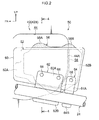
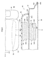
- a side view in Fig. 1 The side portion of a vehicle, to which the vehicle side door structure relating to the present embodiment is applied, is shown in a side view in Fig. 1 .
- a front side door opening portion 12 and a rear side door opening portion 14 are formed in the vehicle longitudinal direction in the side portion of a main body 11 of a vehicle 10.
- a front side door 16 is mounted to the front side door opening portion 12 by hinges 18 so as to be able to open and close
- a rear side door 20 is mounted to the rear side door opening portion 14 by hinges 22 so as to be able open and close.
- the front side door 16 has a door outer panel 40 that is disposed at the vehicle transverse direction outer side, and a door inner panel 42 (see Fig. 3 ) that is disposed at the vehicle transverse direction inner side.
- An impact beam 24 is disposed along the vehicle longitudinal direction at the interior of the front side door 16.
- a front end portion 24A of the impact beam 24 is fixed to the front end portion of the door inner panel 42 via a bracket 26.
- a rear end portion 24B of the impact beam 24 is fixed to the rear end portion of the door inner panel 42 via a bracket 28.
- a vehicle side door structure 50 of the present embodiment is applied to the front side door 16.
- An outer pad 52 is mounted to the rear end portion 24B side of the impact beam 24 at the interior of the front side door 16. The vehicle side door structure 50 is described in detail later.
- An impact beam 30 is disposed along the vehicle longitudinal direction at the interior of the rear side door 20.
- a front end portion 30A and a rear end portion 30B of the impact beam 30 are fixed to the front and rear end portions of a door inner panel (not illustrated) via brackets 32, 34, respectively.
- a door outer pad is mounted to the rear end portion 30B side of the impact beam 30.
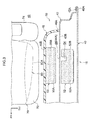
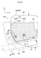
- the mounted states of an outer pad and an inner pad of the front side door 16 to which the vehicle side door structure 50 is applied are shown in Fig. 2 in an enlarged side view that is seen from the vehicle transverse direction outer side. Further, the mounted states of the outer pad and the inner pad of the front side door 16 are shown in Fig. 3 in a plan sectional view, and the mounted states of the outer pad and the inner pad of the front side door 16 are shown in Fig. 4 in a vertical sectional view (a vertical sectional view taken along line 4-4 of Fig. 2 ). As shown in Fig.
- a peripheral edge portion 40A of the door outer panel 40 that is made of metal is made integral by a hemming process with a peripheral edge portion 42A of the door inner panel 42 that is made of metal, so as to structure a closed cross-section.
- a vertical wall portion 42B that projects-out toward the vehicle transverse direction inner side from the peripheral edge portion 42A and that is disposed in the vehicle vertical direction and the vehicle longitudinal direction, is formed at the intermediate portion in the vehicle longitudinal direction of the door inner panel 42.
- a service hole 44 that is formed from an opening that is substantially elliptical, is formed in a vicinity of the central portion of the vertical wall portion 42B at the door inner panel 42.
- a door trim 46 made of resin is mounted by unillustrated clips or the like to the vehicle transverse direction inner side of the vertical wall portion 42B of the door inner panel 42 (see Fig. 3 and the like).
- the door trim 46 is curved, from an end portion 46A in the vehicle longitudinal direction, so as to protrude-out toward the vehicle transverse direction inner side (a vehicle cabin 48 side), and a vertical wall portion 46B is formed along the vehicle vertical direction and the vehicle longitudinal direction at the vehicle transverse direction inner side of this curved surface.
- An inner pad 56 for absorbing impact from the vehicle side surface is disposed between the door inner panel 42 and the door trim 46.
- the inner pad 56 is fixed by an adhesive or the like to the outer side wall surface (the wall surface at the vehicle transverse direction outer side) of the vertical wall portion 46B at the door trim 46.
- the inner pad 56 is disposed so as to span, in the vehicle longitudinal direction, over an outer peripheral edge 44A at the vehicle rear side of the service hole 44. Namely, a front side region 56A in the vehicle longitudinal direction of the inner pad 56 is disposed so as to face the service hole 44, and a rear side region 56B in the vehicle longitudinal direction of the inner pad 56 is disposed so as to face the vertical wall portion 42B of the door inner panel 42 (see Fig.
- the inner pad 56 is formed of an elastic body of foamed resin or rubber or the like.
- the outer pad 52 for absorbing impact from the vehicle side surface is disposed between the door outer panel 40 and the door inner panel 42. As seen in a vehicle side view, the outer pad 52 is disposed so as to overlap the vehicle transverse direction outer side of the inner pad 56. Namely, as seen in a vehicle side view, the outer pad 52 is formed in a substantially rectangular shape, and is disposed so as to span, in the vehicle longitudinal direction, over the outer peripheral edge 44A at the vehicle rear side of the service hole 44.
- the outer pad 52 is formed of an elastic body of foamed resin or rubber or the like.
- a groove portion (notch) 54 that serves as a fragile portion and that is sunken-in toward the vehicle transverse direction outer side, is formed in the wall surface at the vehicle transverse direction inner side of the outer pad 52, along the outer peripheral edge 44A at the vehicle rear side of the service hole 44.
- the outer pad 52 has a front side region (first region) 52A that is disposed at the vehicle front side of the groove portion 54 and so as to face the service hole 44, and a rear side region (second region) 52B that is disposed at the vehicle rear side of the groove portion 54 and so as to face the vertical wall portion 42B of the door inner panel 42 (see Fig. 2 and Fig. 3 ).
- the wall surface at the vehicle transverse direction outer side of the outer pad 52 is fixed by an adhesive or the like to a resin plate 60.
- the resin plate 60 is formed in a substantially rectangular shape, and is formed to be one size larger than the outer shape of the outer pad 52.
- the resin plate 60 is mounted to the impact beam 24 by two brackets 62, 64 that are disposed at the vehicle front and rear sides (see Fig. 2 ). More concretely, the bracket 62 is fixed to the region, that corresponds to the front side region 52A of the outer pad 52, at the resin plate 60, and the bracket 64 is fixed to the region, that corresponds to the rear side region 52B of the outer pad 52, at the resin plate 60.
- the bracket 62 has a mounting portion 62A that is planar and that is disposed in a state of planarly contacting the resin plate 60, and a concave portion 62B that is formed at the lower side of the mounting portion 62A (see Fig. 4 ).
- the impact beam 24 is a pipe-shaped member that has predetermined strength and rigidity.
- the concave portion 62B of the bracket 62 is formed in a substantially semicircular shape so as to project-out toward the vehicle transverse direction inner side.
- the concave portion 62B is disposed so as to contact the peripheral surface of the impact beam 24, and is joined thereto by arc welding (see Fig. 2 and Fig. 4 ).
- Two bolt through-holes are formed in the mounting portion 62A.
- Through-holes 53 that are circular and are one size larger than the bolt through-holes, are formed in the outer pad 52 along the vehicle transverse direction at positions facing the bolt through-holes of the mounting portion 62A (see Fig. 4 ).
- the mounting portion 62A is disposed in a state of planarly contacting the resin plate 60, and the mounting portion 62A and the resin plate 60 are fastened and fixed by bolts 66 and nuts 68 from the both sides thereof. Note that the nuts 68 may be fixed in advance to the resin plate 60, and the bolts 66 may be inserted-through from the mounting portion 62A side and screwed-together.
- the resin plate 60 that corresponds to the front side region 52A is fixed to the impact beam 24 via the bracket 62.
- the bracket 64 is formed such that the width thereof in the vehicle longitudinal direction is shorter than the bracket 62.
- the bracket 64 has a mounting portion 64A that is planar and that is disposed in a state of planarly contacting the resin plate 60, and a concave portion 64B that is formed at the lower side of the mounting portion 64A.
- the concave portion 64B is formed in a substantially semicircular shape so as to project-out toward the vehicle transverse direction inner side.
- the concave portion 64B is disposed so as to contact the peripheral surface of the impact beam 24, and is joined thereto by arc welding (see Fig. 2 ).
- the mounting portion 64A is disposed in a state of planarly contacting the resin plate 60, and the mounting portion 64A and the resin plate 60 are fastened and fixed by one set of the bolt 66 and a nut (not illustrated) from the both sides thereof. Due thereto, the resin plate 60 that corresponds to the rear side region 52B is fixed to the impact beam 24 via the bracket 64. In the state in which the outer pad 52, that is adhered to the resin plate 60, is fixed to the impact beam 24 via the brackets 62, 64, a gap is formed between the surface at the vehicle transverse direction outer side of the outer pad 52 and the surface at the vehicle transverse direction inner side of the door outer panel 40 (see Fig. 3 ).
- the outer pad 52 Due to the groove portion 54 being formed in the wall surface of the outer pad 52 along the outer peripheral edge 44A of the service hole 44, as shown in Fig. 5 , accompanying the incursion of the door outer panel 40 at the time of a side collision, the outer pad 52 hits a vicinity of the outer peripheral edge 44A of the service hole 44 at the door inner panel 42, and the outer pad 52 is broken into the front side region (the first region) 52A and the rear side region (the second region) 52B with the groove portion 54 being the starting point.
- the outer pad 52 is divided into the front side region 52A and the rear side region 52B and moves toward the vehicle transverse direction inner side, and the front side region 52A passes-through the service hole 44 and pushes the inner pad 56 in toward the door trim 46 side, and the rear side region 52B pushes the inner pad 56 in toward the door trim 46 side via the door inner panel 42.
- a fragile portion such as a notch or plural slits (a fold line) or the like is formed in the resin plate 60 along the groove portion 54 (the outer peripheral edge 44A of the service hole 44). Due thereto, accompanying the incursion of the door outer panel 40 at the time of a side collision, the outer pad 52 hits the door inner panel 42 and the resin plate 60 breaks at the fragile portion, and due thereto, independent movement of the front side region 52A and the rear side region 52B is permitted.
- the resin plate 60 may be structured by two parts and disposed at a position corresponding to the front side region 52A and a position corresponding to the rear side region 52B.
- the positions, that correspond to the front side region 52A and the rear side region 52B, at the resin plate 60 are fixed to the impact beam 24 via the individual brackets 62, 64. Therefore, there is a structure in which, after the outer pad 52 breaks into the front side region 52A and the rear side region 52B, the front side region 52A and the rear side region 52B are not detached from the impact beam 24.
- a front seat 70 that serves as a vehicle seat is disposed at the vehicle transverse direction inner side of the front side door 16 at the interior of the vehicle cabin 48.
- the front seat 70 is provided at a position, that faces the front side door opening portion 12, of the vehicle cabin 48.
- the front seat 70 has a seat cushion 72 that supports the buttock region and the femoral region of a passenger 80 who is seated, and a seat back 74 that is provided along the vertical direction at the rear end portion in the vehicle longitudinal direction of the seat cushion 72 and that supports the back portion of the passenger.
- the outer pad 52 and the inner pad 56 are provided at a position, that corresponds to a waist region 80A of the passenger 80 who is seated in the front seat 70, along the vehicle transverse direction.
- the outer pad 52 hits a vicinity of the outer peripheral edge 44A of the service hole 44 at the door inner panel 42, and the outer pad 52 breaks into the front side region (the first region) 52A and the rear side region (the second region) 52B with the groove portion 52 being the starting point. Due thereto, in the initial stage of the collision, the outer pad 52 is divided into the front side region 52A and the rear side region 52B, and they respectively move independently toward the vehicle transverse direction inner side.
- the front side region 52A of the outer pad 52 passes-through the service hole 44 and directly pushes the inner pad 56 in toward the door trim 46 side, and the rear side region 52B of the outer pad 52 pushes the inner pad 56 in toward the door trim 46 side via the door inner panel 42.
- the outer pad catches on the door inner panel 42, and there is the possibility that the front side region that faces the service hole 44 cannot push the inner pad 56 at an early stage.
- the front side region 52A can push the inner pad 56 at an early stage.
- the waist region 80A of the passenger 80 who is seated in the front seat 70 can be pushed over a wide surface area and at an early stage.
- the waist region 80A of the passenger 80 seated in the front seat 70 is pushed at an early stage, and the initial restraining force can be increased. Further, due to the rear side region 52B of the outer pad 52 pushing the inner pad 56 in toward the vehicle transverse direction inner side via the door inner panel 42, the area of restraining the waist region 80A of the passenger 80 seated in the front seat 70 can be broadened.
- the front side region 52A and the rear side region 52B at the outer pad 52 are mounted to the impact beam 24 by the individual brackets 62, 64. Due thereto, even if the outer pad 52 breaks into the front side region 52A and the rear side region 52B at the time of a side collision, the front side region 52A and the rear side region 52B are supported without being detached from the impact beam 24, and therefore, the input to the waist region 80A of the passenger 80 seated in the front seat 70 is stable.
- FIG. 6 A second embodiment of the vehicle side door structure relating to the present invention is described next by using Fig. 6 . Note that, in the second embodiment, structural elements, members and the like that are the same as those of the first embodiment are denoted by the same reference numerals, and detailed description thereof is omitted.
- a plate material 94 that is made of metal is embedded in the interior of the rear side region 52B of an outer pad 92 that faces the vertical wall portion 42B of the door inner panel 42.
- a front end 94A in the vehicle longitudinal direction of the plate material 94 is disposed along the outer peripheral edge 44A of the service hole 44 as seen in a vehicle side view. Due thereto, the border portion between the front end 94A of the plate material 94 at the rear side region 52B of the outer pad 92, and the front side region 52A in which the plate material 94 is not embedded, is a fragile portion that becomes the starting point of breakage at the time of a side collision.
- the outer pad 92 breaks into the front side region 52A and the rear side region 52B with the border portion between the front end 94A of the plate material 94 and the front side region 52A being the starting point. Due thereto, the front side region 52A of the outer pad 92 passes-through the service hole 44 and pushes the inner pad 56 in toward the vehicle transverse direction inner side, and the rear side region 52B of the outer pad 92 pushes the inner pad 56 in toward the vehicle transverse direction inner side via the door inner panel 42.
- the waist region 80A of the passenger 80 seated in the front seat 70 can be pushed at an early stage over a wide surface area. Further, by embedding the plate material 94 that is made of metal into the rear side region 52B of the outer pad 92 and making the rear side region 52B have a higher rigidity than the front side region 52A, at the time of a side collision, the inner pad 56 can be pushed more strongly toward the door trim 46 side via the door inner panel 42.
- the plate material 94 that is made of metal is embedded in the interior of the rear side region 52B of the outer pad 92.
- a plate material that is made of metal may be embedded in the interior of the front side region 52A of the outer pad 92, and the rear end of the plate material may be disposed along the outer peripheral edge 44A of the service hole 44 as seen in a vehicle side view.
- FIG. 7 A third embodiment of the vehicle side door structure relating to the present invention is described next by using Fig. 7 . Note that, in the third embodiment, structural elements, members and the like that are the same as those of the first embodiment and the second embodiment are denoted by the same reference numerals, and detailed description thereof is omitted.
- a cut-out portion 104 serving as a fragile portion is formed at the vehicle transverse direction inner side of the rear side region 52B of an outer pad 102 that faces the vertical wall portion 42B of the door inner panel 42.
- a front end 104A of the cut-out portion 104 is disposed along the outer peripheral edge 44A of the service hole 44.
- the outer pad 102 breaks into the front side region 52A and the rear side region 52B with the vicinity of the front end 104A of the cut-out portion 104 being the starting point. Due thereto, the front side region 52A of the outer pad 102 passes-through the service hole 44 and pushes the inner pad 56 in toward the vehicle transverse direction inner side, and the rear side region 52B of the outer pad 102 pushes the inner pad 56 in toward the vehicle transverse direction inner side via the door inner panel 42. Therefore, the waist region 80A of the passenger 80 seated in the front seat 70 can be pushed at an early stage over a wide surface area.
- the fragile portion that becomes the starting point of breaking into the front side region 52A and the rear side region 52B of the outer pad at the time of a side collision, is not limited to the vehicle side door structures 50, 90, 100 of the first embodiment through the third embodiment, and may be another structure.
- the fragile portion may be a structure in which plural slits are formed in the outer pad along the outer peripheral edge 44A of the service hole 44, or a structure in which a hollow hole is provided at the interior of the outer pad along the outer peripheral edge 44A of the service hole 44, or the like. Namely, it suffices for the fragile portion to be a structure that provides the outer pad with a difference in strengths along the outer peripheral edge 44A of the service hole 44.
- the front side region 52A and the rear side region 52B of the outer pad 52, 92, 102 are formed by an elastic body that has the same hardness and is of foamed resin or the like for example.
- the present invention is not limited to this, and the rear side region 52B that faces the vertical wall portion 42B of the door inner panel 42 may be structured to be harder than the front side region 52A that faces the service hole 44.
- the rear side region 52B can be made to be hard by making the foaming rate of the rear side region 52B, that faces the vertical wall portion 42B of the door inner panel 42, be lower than the foaming rate of the front side region 52A that faces the service hole 44.
- the rear side region 52B can be made to be harder than the front side region 52A by changing the cross-sectional shape of the outer pad (e.g., a hollow cross-section or a U-shaped cross-section or the like). Due to this structure, at the time of a side collision, the rear side region 52B can more strongly push the inner pad 56 via the vertical wall portion 42B of the door inner panel 42.
- the cross-sectional shape of the outer pad e.g., a hollow cross-section or a U-shaped cross-section or the like. Due to this structure, at the time of a side collision, the rear side region 52B can more strongly push the inner pad 56 via the vertical wall portion 42B of the door inner panel 42.
- FIG. 8 A fourth embodiment of the vehicle side door structure relating to the present invention is described next by using Fig. 8 . Note that, in the fourth embodiment, structural elements, members and the like that are the same as those of the first embodiment through the third embodiment are denoted by the same reference numerals, and detailed description thereof is omitted.
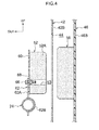
- FIG. 8 The mounted state of an outer pad 122, that is used in a front side door to which a vehicle side door structure 120 is applied, is shown in Fig. 8 in a side view seen from the vehicle transverse direction inner side.
- the outer pad 122 is divided in advance, along the outer peripheral edge 44A at the vehicle rear side of the service hole 44, into a front side region (first region) 122A that faces the service hole 44 and a rear side region (second region) 122B that faces the vertical wall portion 42B of the door inner panel 42.
- the front side region 122A and the rear side region 122 B are fixed by an adhesive or the like to the resin plate 60 in a state in which a gap is formed between the rear end surface of the front side region 122A and the front end surface of the rear side region 122B.
- a fragile portion such as a notch or plural slits (a fold line) or the like is formed in the resin plate 60 along the outer peripheral edge 44A of the service hole 44. Due to the resin plate 60 being broken with the fragile portion being the starting point at the time of a side collision, independent movement of the front side region 122A and the rear side region 122B is permitted.
- the front side region 122A and the rear side region 122B of the outer pad 122 are formed by elastic bodies that are formed from foamed resin or rubber, and the rear side region 122B is structured to be harder than the front side region 122A.
- the rear side region 122B is made to be hard by making the foaming rate of the rear side region 122B lower than the foaming rate of the front side region 122A.
- the outer pad 122 is divided in advance into the front side region 122A and the rear side region 122B.
- the resin plate 60 is broken with the fragile portion being the starting point, and the front side region 122A and the rear side region 122B independently move toward the vehicle transverse direction inner side.
- the front side region 122A passes-through the service hole 44 and pushes the inner pad 56 (see Fig.
- the rear side region 122B is structured to be harder than the front side region 122A, and, at the time of a side collision, the rear side region 122B can more strongly push the inner pad 56 via the vertical wall portion 42B of the door inner panel 42.
- the rear side region 122B is made to be hard by making the foaming rate of the rear side region 122B lower than the foaming rate of the front side region 122A.
- the present invention is not limited to this and may be a structure in which the rear side region 122B is made to be harder than or have a higher rigidity than the front side region 122A by varying the cross-sectional shapes of the front side region 122A and the rear side region 122B (e.g., a hollow cross-section, a change in the thickness in the vehicle transverse direction, or the like), or by embedding a metal plate in the interior of the rear side region 122B, or the like.
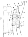
- FIG. 9 A fifth embodiment of a passenger protecting system relating to the present invention is described next by using Fig. 9 .
- structural elements, members and the like that are the same as those of the first embodiment through the fourth embodiment are denoted by the same reference numerals, and detailed description thereof is omitted.
- a side airbag device 152 is installed in the side portion at the vehicle transverse direction outer side of the seat back 74 that structures a portion of the front seat (vehicle seat) 70.
- the side airbag device 152 has a side airbag 154 that serves as a bag body and is stored by being folded-up within a case 152A, and an inflator (not illustrated) that, when a side collision state is detected by a side collision sensor (not shown) and electricity is supplied by a controller (not shown), generates a large amount of gas and jets the gas out into the side airbag 154, and the like.
- a side collision sensor not shown
- electricity is supplied by a controller (not shown)
- a controller not shown
- this side airbag device 152 when a large acceleration that is greater than or equal to a predetermined value is applied to the vehicle due to a side collision, this state is detected by the side collision sensor, and a predetermined current is supplied from the controller to an ignition device of the inflator.
- the inflator operates and generates a large amount of gas, and the side surface of the seat back 74 opens, and the side airbag 154 is inflated and expanded. Namely, by inflating and expanding the side airbag 154 between the door trim 46 and the passenger 80 who is seated in the front seat 70, kinetic energy is absorbed and the passenger is protected.
- the side airbag 154 when the side airbag 154 is inflated and expanded between the door trim 46 and the passenger 80 seated in the front seat 70 at the time of a side collision, the surfaces at both vehicle transverse direction sides of the side airbag 154 hit the waist region 80A of the passenger 80 and the door trim 46. Due thereto, the side airbag 154 pushes the door trim 46 toward the vehicle transverse direction outer side, and is inputted from the end portion 46A of the door trim 46 to the door inner panel 42 as shown by arrow B.
- the outer pad 52 breaks into the front side region 52A and the rear side region 52B with the groove portion 54 being the starting point. Due thereto, accompanying the incursion of the door outer panel 40, the front side region 52A and the rear side region 52B can independently move toward the vehicle transverse direction inner side.
- the outer pad 52 before the outer pad 52 is divided due to the incursion of the door outer panel 40, the outer pad 52 can be divided due to the inflation and expansion of the side airbag 154, and the waist region 80A of the passenger 80 can be pushed at an early stage over a wide surface area.
- the side airbag device 152 is provided at the side portion at the vehicle transverse direction outer side of the seat back 74.
- a side airbag device 170 is provided at the door inner panel 42 side at the rear portion of the door trim 46 interior, and, at the time of a side collision, the door trim 46 opens and the side airbag is inflated and expanded.
- the outer pad 52 can be broken into the front side region 52A and the rear side region 52B with the groove portion 54 as the starting point by utilizing the input to the door inner panel 42.
- the front side region (the first region) that faces the service hole 44 and the rear side region (the second region) that faces the door inner panel 42 are provided due to the outer pad being disposed so as to span, in the vehicle longitudinal direction, over the outer peripheral edge 44A at the vehicle rear side of the service hole 44.
- the present invention is not limited to this structure.
- there may be a structure in which the rear side region (the first region) that faces the service hole 44 and the front side region (the second region) that faces the door inner panel are provided due to the outer pad being disposed so as to span, in the vehicle longitudinal direction, over the outer peripheral edge 44A at the front side of the service hole 44.
- the rear side region (the first region) may pass-through the service hole 44 and push the inner pad toward the door trim side
- the front side region (the second region) may separate from the rear side region and push the inner pad toward the door trim side via the door inner panel.
- the vehicle side door structure 50 of the present invention is applied to the front side door 16.
- the present invention is not limited to this, and the vehicle side door structure 50 of the first embodiment through the fifth embodiment may be applied to the rear side door 20.
Landscapes
- Engineering & Computer Science (AREA)
- Mechanical Engineering (AREA)
- Air Bags (AREA)
- Body Structure For Vehicles (AREA)
Abstract
Description
- The present invention relates to a vehicle side door structure and a passenger protecting system.
- Patent Document 1 (Japanese Patent Application Laid-Open (JP-A) No.
07-232554 - Further, Patent Document 2 (
JP-A No. 2005-138838 - [Patent Document 1]
JP-A No. 07-232554 - [Patent Document 2]
JP-A No. 2005-138838 - [Patent Document 3]
JP-A No. 2008-254635 - In a case in accordance with above-described
Patent Document 1, at the time of a side collision, due to the door pad pushing the trim pad without hitting the inner panel, it is possible that the energy absorption amount will be increased. However, in a vehicle in which a large work opening cannot be formed at a position corresponding to the waist region of a passenger seated in the vehicle seat, at the time of a side collision, it is difficult to push the waist region of the passenger at an early stage over a wide area (surface area) by the door pad and trim pad. Further, because of the structure in which the door pad is detached from the mounting portion of the impact bar at the time of a side collision, it is difficult to stably and uniformly push the waist region of the passenger. - Further, in a case in accordance with above-described Patent Document 2, the second impact absorbing pad passes-through the opening hole of the inner panel and is mounted to the inner panel via a holding member. In a vehicle in which a large opening hole cannot be formed at a position corresponding to the waist region of a passenger seated in the vehicle seat, at the time of a side collision, it is difficult to push the waist region of the passenger at an early stage over a wide surface area by the respective impact absorbing pads.
- In consideration of the above-described circumstances, an object of the present invention is to provide a vehicle side door structure and passenger protecting system that, at the time of a side collision, can push the waist region of a passenger at an early stage over a wide surface area.
- A vehicle side door structure of a first aspect relating to the present invention comprises: a door outer panel that is disposed at a vehicle transverse direction outer side; a door inner panel that is disposed at a vehicle transverse direction inner side, and is formed in a shape of a bag together with the door outer panel, and in which a service hole is formed in an intermediate portion in a vehicle longitudinal direction; a door trim that is mounted to a vehicle transverse direction inner side of the door inner panel; an inner pad that is disposed between the door inner panel and the door trim, and is provided so as to span, in the vehicle longitudinal direction, over an outer peripheral edge of the service hole as seen in a vehicle side view, and that absorbs impact from a vehicle side surface; and an outer pad that is disposed between the door outer panel and the door inner panel, and is provided so as to overlap a vehicle transverse direction outer side of the inner pad as seen in a vehicle side view, and that has a first region that, at a time of a side collision, is pushed by the door outer panel, passes-through the service hole and pushes the inner pad toward the door trim side, and a second region that, at a time of a side collision, separates from the first region and pushes the inner pad toward the door trim side via the door inner panel.
- In a vehicle side door structure of a second aspect relating to the present invention, in the vehicle side door structure of the first aspect, a fragile portion is provided at the outer pad along the outer peripheral edge of the service hole so as to become a starting point of breaking the outer pad into the first region and the second region at a time of a side collision.
- In a vehicle side door structure of a third aspect relating to the present invention, in the vehicle side door structure of the first aspect or the second aspect, an impact beam extends along the vehicle longitudinal direction between the door outer panel and the door inner panel, and the first region and the second region at the outer pad are mounted to the impact beam by individual brackets.
- In a vehicle side door structure of a fourth aspect relating to the present invention, in the vehicle side door structure of any one aspect of the first aspect through the third aspect, at the outer pad, the second region is structured to be harder than, or have a higher rigidity than, the first region.
- In a vehicle side door structure of a fifth aspect relating to the present invention, in the vehicle side door structure of the first aspect, the outer pad is divided in advance along the outer peripheral edge of the service hole into the first region and the second region.
- In a vehicle side door structure of a sixth aspect relating to the present invention, in the vehicle side door structure of the fifth aspect, an impact beam extends along the vehicle longitudinal direction between the door outer panel and the door inner panel, and the first region and the second region at the outer pad are mounted to the impact beam by individual brackets.
- In a vehicle side door structure of a seventh aspect relating to the present invention, in the vehicle side door structure of the fifth aspect or the sixth aspect, at the outer pad, the second region is structured to be harder than, or have a higher rigidity than, the first region.
- A passenger protecting system of an eighth aspect relating to the present invention comprises the vehicle side door structure of any one aspect of the second aspect through the fourth aspect, wherein a side airbag device, at which, at a time of a side collision, a bag body inflates and expands between the door trim and a waist region of a passenger seated in a vehicle seat, is provided at an interior of the door trim or at a side portion of a seat back that structures a portion of the vehicle seat.
- In accordance with the vehicle side door structure of the first aspect relating to the present invention, the inner pad is provided so as to span, in the vehicle longitudinal direction, over the outer peripheral edge of the service hole as seen in a vehicle side view, between the door inner panel in which the service hole is formed and the door trim that is mounted to the vehicle transverse direction inner side thereof. Further, the outer pad is provided between the door outer panel and the door inner panel so as to overlap the vehicle transverse direction outer side of the inner pad as seen in a vehicle side view. Namely, the outer pad is provided with a first region that faces the service hole and a second region that corresponds to the door inner panel. Further, when the door outer panel intrudes in toward the vehicle transverse direction inner side at the time of a side collision, the first region that is pushed by the door outer panel passes-through the service hole and pushes the inner pad toward the door trim side, and further, the second region that is pushed by the door outer panel separates from the first region and pushes the inner pad toward the door trim side via the door inner panel.
Therefore, even if the outer pad is disposed so as to span, in the vehicle longitudinal direction, over the outer peripheral edge of the service hole as seen in a vehicle side view, the outer pad catching on the door inner panel and the region that faces the service hole not being able to push the inner pad at an early stage is remedied. Accordingly, at the time of a side collision, the waist region of the passenger seated in the vehicle seat can be pushed at an early stage over a wide surface area. - In accordance with the vehicle side door structure of the second aspect relating to the present invention, the fragile portion is provided at the outer pad along the outer peripheral edge of the service hole. Due to the fragile portion of the outer pad hitting a vicinity of the outer peripheral edge of the service hole at the door inner panel accompanying the incursion of the outer panel at the time of a side collision, the outer pad breaks into the first region and the second region with the fragile portion being the starting point. Due thereto, the outer pad is divided into the first region and the second region, and can independently move toward the door trim side. Therefore, the inner pad can be pushed at an early stage over a wide range by the first region and the second region.
- In accordance with the vehicle side door structure of the fifth aspect relating to the present invention, the outer pad is divided in advance into the first region and the second region along the outer peripheral edge of the service hole. Accompanying the incursion of the outer panel at the time of a side collision, the first region and the second region independently move toward the door trim side. Therefore, the inner pad can be pushed at an even earlier stage over a wide range by the first region and the second region.
- In accordance with the vehicle side door structure of the third aspect or the sixth aspect relating to the present invention, the first region and the second region at the outer pad are mounted to the impact beam by individual brackets. At the time of a side collision, the first region and the second region are supported without being detached from the impact beam. Therefore, as compared with a case in which the first region and the second region are detached from the impact beam, the input to the waist region of the passenger seated in the vehicle seat is stable.
- In accordance with the vehicle side door structure of the fourth aspect or the seventh aspect relating to the present invention, at the outer pad, the second region is structured to be harder than or have a higher rigidity than the first region. At the time of a side collision, the second region can more strongly push the inner pad via the door inner panel.
- In accordance with the passenger protecting system of the eighth aspect relating to the present invention, the side airbag device is provided at the side portion of the seat back that structures a portion of the vehicle seat, or at the interior of the door trim. At the time of a side collision, the side airbag inflates and expands between the door trim and the waist region of the passenger seated in the vehicle seat. Therefore, the impact, that is transmitted from the door trim to the door inner panel due to the inflation and expansion of the side air bag, is utilized, and the outer pad can break into the first region and the second region at an early stage with the fragile portion being the starting point.
- In accordance with the vehicle side door structure and passenger protecting system relating to the present invention, at the time of a side collision, the waist region of a passenger can be pushed at an early stage over a wide surface area.
-
-
Fig. 1 is a side view showing a side portion of a vehicle to which a vehicle side door structure relating to a first embodiment is applied. -
Fig. 2 is an enlarged side view of main portions showing, in a state viewed from a vehicle transverse direction outer side, the mounted states of an outer pad and an inner pad that are used in a front side door to which the vehicle side door structure shown inFig. 1 is applied. -
Fig. 3 is a plan sectional view showing the mounted states of the outer pad and the inner pad that are used in the front side door shown inFig. 2 . -
Fig. 4 is a vertical sectional view taken along line 4-4 ofFig. 2 . -
Fig. 5 is a plan sectional view that corresponds toFig. 3 and shows deformed states of the outer pad and the inner pad at the front side door at the time of a side collision. -
Fig. 6 is a plan sectional view, corresponding toFig. 3 , of a vehicle side door structure relating to a second embodiment. -
Fig. 7 is a plan sectional view, corresponding toFig. 3 , of a vehicle side door structure relating to a third embodiment. -
Fig. 8 is an enlarged side view of main portions showing, in a state viewed from a vehicle transverse direction inner side of a door inner panel, the mounted state of an outer pad that is used in the front side door to which a vehicle side door structure relating to a fourth embodiment is applied. -
Fig. 9 is a plan sectional view showing a state in which a side airbag of a side airbag device has inflated and expanded between the front side door and a vehicle seat to which a passenger protecting system relating to a fifth embodiment is applied. - A first embodiment of a vehicle side door structure relating to the present invention is described hereinafter by using
Fig. 1 through Fig. 5 . Note that arrow FR that is shown appropriately in these drawings indicates the vehicle front side, arrow UP indicates the vehicle upper side, and arrow OUT indicates the vehicle transverse direction outer side. - The side portion of a vehicle, to which the vehicle side door structure relating to the present embodiment is applied, is shown in a side view in
Fig. 1 . As shown inFig. 1 , a front sidedoor opening portion 12 and a rear sidedoor opening portion 14 are formed in the vehicle longitudinal direction in the side portion of amain body 11 of avehicle 10. Afront side door 16 is mounted to the front sidedoor opening portion 12 byhinges 18 so as to be able to open and close, and arear side door 20 is mounted to the rear sidedoor opening portion 14 byhinges 22 so as to be able open and close. Thefront side door 16 has a doorouter panel 40 that is disposed at the vehicle transverse direction outer side, and a door inner panel 42 (seeFig. 3 ) that is disposed at the vehicle transverse direction inner side. - An
impact beam 24 is disposed along the vehicle longitudinal direction at the interior of thefront side door 16. Afront end portion 24A of theimpact beam 24 is fixed to the front end portion of the doorinner panel 42 via abracket 26. Arear end portion 24B of theimpact beam 24 is fixed to the rear end portion of the doorinner panel 42 via abracket 28.
A vehicleside door structure 50 of the present embodiment is applied to thefront side door 16. Anouter pad 52 is mounted to therear end portion 24B side of theimpact beam 24 at the interior of thefront side door 16. The vehicleside door structure 50 is described in detail later. - An
impact beam 30 is disposed along the vehicle longitudinal direction at the interior of therear side door 20. Afront end portion 30A and arear end portion 30B of theimpact beam 30 are fixed to the front and rear end portions of a door inner panel (not illustrated) viabrackets rear end portion 30B side of theimpact beam 30. - The mounted states of an outer pad and an inner pad of the
front side door 16 to which the vehicleside door structure 50 is applied are shown inFig. 2 in an enlarged side view that is seen from the vehicle transverse direction outer side. Further, the mounted states of the outer pad and the inner pad of thefront side door 16 are shown inFig. 3 in a plan sectional view, and the mounted states of the outer pad and the inner pad of thefront side door 16 are shown inFig. 4 in a vertical sectional view (a vertical sectional view taken along line 4-4 ofFig. 2 ). As shown inFig. 3 , at thefront side door 16, aperipheral edge portion 40A of the doorouter panel 40 that is made of metal is made integral by a hemming process with aperipheral edge portion 42A of the doorinner panel 42 that is made of metal, so as to structure a closed cross-section. Avertical wall portion 42B, that projects-out toward the vehicle transverse direction inner side from theperipheral edge portion 42A and that is disposed in the vehicle vertical direction and the vehicle longitudinal direction, is formed at the intermediate portion in the vehicle longitudinal direction of the doorinner panel 42. As shown inFig. 2 through Fig. 4 , aservice hole 44, that is formed from an opening that is substantially elliptical, is formed in a vicinity of the central portion of thevertical wall portion 42B at the doorinner panel 42. - A door trim 46 made of resin is mounted by unillustrated clips or the like to the vehicle transverse direction inner side of the
vertical wall portion 42B of the door inner panel 42 (seeFig. 3 and the like). The door trim 46 is curved, from anend portion 46A in the vehicle longitudinal direction, so as to protrude-out toward the vehicle transverse direction inner side (avehicle cabin 48 side), and avertical wall portion 46B is formed along the vehicle vertical direction and the vehicle longitudinal direction at the vehicle transverse direction inner side of this curved surface. - An
inner pad 56 for absorbing impact from the vehicle side surface, is disposed between the doorinner panel 42 and thedoor trim 46. Theinner pad 56 is fixed by an adhesive or the like to the outer side wall surface (the wall surface at the vehicle transverse direction outer side) of thevertical wall portion 46B at thedoor trim 46. As seen in a vehicle side view, theinner pad 56 is disposed so as to span, in the vehicle longitudinal direction, over an outerperipheral edge 44A at the vehicle rear side of theservice hole 44. Namely, afront side region 56A in the vehicle longitudinal direction of theinner pad 56 is disposed so as to face theservice hole 44, and arear side region 56B in the vehicle longitudinal direction of theinner pad 56 is disposed so as to face thevertical wall portion 42B of the door inner panel 42 (seeFig. 2 andFig. 3 ). In the state in which theinner pad 56 is fixed to thevertical wall portion 46B of thedoor trim 46, a gap is provided between the outer side wall surface of therear side region 56B of theinner pad 56 and the inner side wall surface of the doorinner panel 42. Theinner pad 56 is formed of an elastic body of foamed resin or rubber or the like. - The
outer pad 52 for absorbing impact from the vehicle side surface is disposed between the doorouter panel 40 and the doorinner panel 42. As seen in a vehicle side view, theouter pad 52 is disposed so as to overlap the vehicle transverse direction outer side of theinner pad 56. Namely, as seen in a vehicle side view, theouter pad 52 is formed in a substantially rectangular shape, and is disposed so as to span, in the vehicle longitudinal direction, over the outerperipheral edge 44A at the vehicle rear side of theservice hole 44. Theouter pad 52 is formed of an elastic body of foamed resin or rubber or the like. - A groove portion (notch) 54, that serves as a fragile portion and that is sunken-in toward the vehicle transverse direction outer side, is formed in the wall surface at the vehicle transverse direction inner side of the
outer pad 52, along the outerperipheral edge 44A at the vehicle rear side of theservice hole 44. Theouter pad 52 has a front side region (first region) 52A that is disposed at the vehicle front side of thegroove portion 54 and so as to face theservice hole 44, and a rear side region (second region) 52B that is disposed at the vehicle rear side of thegroove portion 54 and so as to face thevertical wall portion 42B of the door inner panel 42 (seeFig. 2 andFig. 3 ). - As shown in
Fig. 2 andFig. 4 , the wall surface at the vehicle transverse direction outer side of theouter pad 52 is fixed by an adhesive or the like to aresin plate 60. As seen in a vehicle side view, theresin plate 60 is formed in a substantially rectangular shape, and is formed to be one size larger than the outer shape of theouter pad 52. - The
resin plate 60 is mounted to theimpact beam 24 by twobrackets Fig. 2 ). More concretely, thebracket 62 is fixed to the region, that corresponds to thefront side region 52A of theouter pad 52, at theresin plate 60, and thebracket 64 is fixed to the region, that corresponds to therear side region 52B of theouter pad 52, at theresin plate 60. - The
bracket 62 has a mountingportion 62A that is planar and that is disposed in a state of planarly contacting theresin plate 60, and aconcave portion 62B that is formed at the lower side of the mountingportion 62A (seeFig. 4 ). Further, theimpact beam 24 is a pipe-shaped member that has predetermined strength and rigidity. As seen in a vehicle rear view, theconcave portion 62B of thebracket 62 is formed in a substantially semicircular shape so as to project-out toward the vehicle transverse direction inner side. Theconcave portion 62B is disposed so as to contact the peripheral surface of theimpact beam 24, and is joined thereto by arc welding (seeFig. 2 andFig. 4 ). Two bolt through-holes are formed in the mountingportion 62A. Through-holes 53, that are circular and are one size larger than the bolt through-holes, are formed in theouter pad 52 along the vehicle transverse direction at positions facing the bolt through-holes of the mountingportion 62A (seeFig. 4 ). The mountingportion 62A is disposed in a state of planarly contacting theresin plate 60, and the mountingportion 62A and theresin plate 60 are fastened and fixed bybolts 66 andnuts 68 from the both sides thereof. Note that the nuts 68 may be fixed in advance to theresin plate 60, and thebolts 66 may be inserted-through from the mountingportion 62A side and screwed-together. Due to the mountingportion 62A and theresin plate 60 being fastened and fixed by the two sets ofbolts 66 andnuts 68 at the vehicle front and rear sides, theresin plate 60 that corresponds to thefront side region 52A is fixed to theimpact beam 24 via thebracket 62. - The
bracket 64 is formed such that the width thereof in the vehicle longitudinal direction is shorter than thebracket 62. Thebracket 64 has a mountingportion 64A that is planar and that is disposed in a state of planarly contacting theresin plate 60, and aconcave portion 64B that is formed at the lower side of the mountingportion 64A. As seen in a vehicle rear view, theconcave portion 64B is formed in a substantially semicircular shape so as to project-out toward the vehicle transverse direction inner side. Theconcave portion 64B is disposed so as to contact the peripheral surface of theimpact beam 24, and is joined thereto by arc welding (seeFig. 2 ). The mountingportion 64A is disposed in a state of planarly contacting theresin plate 60, and the mountingportion 64A and theresin plate 60 are fastened and fixed by one set of thebolt 66 and a nut (not illustrated) from the both sides thereof. Due thereto, theresin plate 60 that corresponds to therear side region 52B is fixed to theimpact beam 24 via thebracket 64. In the state in which theouter pad 52, that is adhered to theresin plate 60, is fixed to theimpact beam 24 via thebrackets outer pad 52 and the surface at the vehicle transverse direction inner side of the door outer panel 40 (seeFig. 3 ). - Due to the
groove portion 54 being formed in the wall surface of theouter pad 52 along the outerperipheral edge 44A of theservice hole 44, as shown inFig. 5 , accompanying the incursion of the doorouter panel 40 at the time of a side collision, theouter pad 52 hits a vicinity of the outerperipheral edge 44A of theservice hole 44 at the doorinner panel 42, and theouter pad 52 is broken into the front side region (the first region) 52A and the rear side region (the second region) 52B with thegroove portion 54 being the starting point. Due thereto, theouter pad 52 is divided into thefront side region 52A and therear side region 52B and moves toward the vehicle transverse direction inner side, and thefront side region 52A passes-through theservice hole 44 and pushes theinner pad 56 in toward the door trim 46 side, and therear side region 52B pushes theinner pad 56 in toward the door trim 46 side via the doorinner panel 42. - Although illustration thereof is omitted, a fragile portion such as a notch or plural slits (a fold line) or the like is formed in the
resin plate 60 along the groove portion 54 (the outerperipheral edge 44A of the service hole 44). Due thereto, accompanying the incursion of the doorouter panel 40 at the time of a side collision, theouter pad 52 hits the doorinner panel 42 and theresin plate 60 breaks at the fragile portion, and due thereto, independent movement of thefront side region 52A and therear side region 52B is permitted. Further, there may be a structure in which a cut-out portion is provided at theresin plate 60 at the upper side of thebracket 64 and the vehicle rear side of the outerperipheral edge 44A of theservice hole 44 as seen in a vehicle side view, and theresin plate 60 breaks easily along the outerperipheral edge 44A of theservice hole 44 at the time of a side collision.
Further, although theresin plate 60 is a single part in the present embodiment, theresin plate 60 may be structured by two parts and disposed at a position corresponding to thefront side region 52A and a position corresponding to therear side region 52B. - Further, the positions, that correspond to the
front side region 52A and therear side region 52B, at theresin plate 60 are fixed to theimpact beam 24 via theindividual brackets outer pad 52 breaks into thefront side region 52A and therear side region 52B, thefront side region 52A and therear side region 52B are not detached from theimpact beam 24. - As shown in
Fig. 3 , afront seat 70 that serves as a vehicle seat is disposed at the vehicle transverse direction inner side of thefront side door 16 at the interior of thevehicle cabin 48. Thefront seat 70 is provided at a position, that faces the front sidedoor opening portion 12, of thevehicle cabin 48. Thefront seat 70 has aseat cushion 72 that supports the buttock region and the femoral region of apassenger 80 who is seated, and a seat back 74 that is provided along the vertical direction at the rear end portion in the vehicle longitudinal direction of theseat cushion 72 and that supports the back portion of the passenger. Theouter pad 52 and theinner pad 56 are provided at a position, that corresponds to awaist region 80A of thepassenger 80 who is seated in thefront seat 70, along the vehicle transverse direction. - The operation and effects of the present embodiment are described next.
- As shown in
Fig. 5 , when the doorouter panel 40 intrudes in toward the vehicle transverse direction inner side (in the arrow A direction) at the time of a side collision, accompanying the incursion of the doorouter panel 40, theouter pad 52 hits a vicinity of the outerperipheral edge 44A of theservice hole 44 at the doorinner panel 42, and theouter pad 52 breaks into the front side region (the first region) 52A and the rear side region (the second region) 52B with thegroove portion 52 being the starting point. Due thereto, in the initial stage of the collision, theouter pad 52 is divided into thefront side region 52A and therear side region 52B, and they respectively move independently toward the vehicle transverse direction inner side. Therefore, accompanying the incursion of the doorouter panel 40, thefront side region 52A of theouter pad 52 passes-through theservice hole 44 and directly pushes theinner pad 56 in toward the door trim 46 side, and therear side region 52B of theouter pad 52 pushes theinner pad 56 in toward the door trim 46 side via the doorinner panel 42. - Namely, in a structure in which the outer pad does not break, the outer pad catches on the door
inner panel 42, and there is the possibility that the front side region that faces theservice hole 44 cannot push theinner pad 56 at an early stage. However, in the vehicleside door structure 50 of the present embodiment, due to thefront side region 52A and therear side region 52B breaking, thefront side region 52A can push theinner pad 56 at an early stage. As a result, at the time of a side collision, thewaist region 80A of thepassenger 80 who is seated in thefront seat 70 can be pushed over a wide surface area and at an early stage. More concretely, due to thefront side region 52A of theouter pad 52 pushing theinner pad 56 in toward the vehicle transverse direction inner side, thewaist region 80A of thepassenger 80 seated in thefront seat 70 is pushed at an early stage, and the initial restraining force can be increased. Further, due to therear side region 52B of theouter pad 52 pushing theinner pad 56 in toward the vehicle transverse direction inner side via the doorinner panel 42, the area of restraining thewaist region 80A of thepassenger 80 seated in thefront seat 70 can be broadened. - Further, as shown in
Fig. 2 , thefront side region 52A and therear side region 52B at theouter pad 52 are mounted to theimpact beam 24 by theindividual brackets outer pad 52 breaks into thefront side region 52A and therear side region 52B at the time of a side collision, thefront side region 52A and therear side region 52B are supported without being detached from theimpact beam 24, and therefore, the input to thewaist region 80A of thepassenger 80 seated in thefront seat 70 is stable. - A second embodiment of the vehicle side door structure relating to the present invention is described next by using
Fig. 6 . Note that, in the second embodiment, structural elements, members and the like that are the same as those of the first embodiment are denoted by the same reference numerals, and detailed description thereof is omitted. - As shown in
Fig. 6 , in a vehicleside door structure 90 of the present embodiment, aplate material 94 that is made of metal (e.g., made of iron) is embedded in the interior of therear side region 52B of anouter pad 92 that faces thevertical wall portion 42B of the doorinner panel 42. Afront end 94A in the vehicle longitudinal direction of theplate material 94 is disposed along the outerperipheral edge 44A of theservice hole 44 as seen in a vehicle side view. Due thereto, the border portion between thefront end 94A of theplate material 94 at therear side region 52B of theouter pad 92, and thefront side region 52A in which theplate material 94 is not embedded, is a fragile portion that becomes the starting point of breakage at the time of a side collision. - Due to the
rear side region 52B of theouter pad 92 hitting a vicinity of the outerperipheral edge 44A of theservice hole 44 at the doorinner panel 42 accompanying the incursion of the doorouter panel 40 at the time of a side collision, theouter pad 92 breaks into thefront side region 52A and therear side region 52B with the border portion between thefront end 94A of theplate material 94 and thefront side region 52A being the starting point. Due thereto, thefront side region 52A of theouter pad 92 passes-through theservice hole 44 and pushes theinner pad 56 in toward the vehicle transverse direction inner side, and therear side region 52B of theouter pad 92 pushes theinner pad 56 in toward the vehicle transverse direction inner side via the doorinner panel 42. Therefore, thewaist region 80A of thepassenger 80 seated in thefront seat 70 can be pushed at an early stage over a wide surface area.
Further, by embedding theplate material 94 that is made of metal into therear side region 52B of theouter pad 92 and making therear side region 52B have a higher rigidity than thefront side region 52A, at the time of a side collision, theinner pad 56 can be pushed more strongly toward the door trim 46 side via the doorinner panel 42. - Note that, in the present embodiment, the
plate material 94 that is made of metal is embedded in the interior of therear side region 52B of theouter pad 92. However, instead of this, a plate material that is made of metal may be embedded in the interior of thefront side region 52A of theouter pad 92, and the rear end of the plate material may be disposed along the outerperipheral edge 44A of theservice hole 44 as seen in a vehicle side view. - A third embodiment of the vehicle side door structure relating to the present invention is described next by using
Fig. 7 . Note that, in the third embodiment, structural elements, members and the like that are the same as those of the first embodiment and the second embodiment are denoted by the same reference numerals, and detailed description thereof is omitted. - As shown in
Fig. 7 , in a vehicleside door structure 100 of the present embodiment, a cut-outportion 104 serving as a fragile portion is formed at the vehicle transverse direction inner side of therear side region 52B of anouter pad 102 that faces thevertical wall portion 42B of the doorinner panel 42. As seen in a vehicle side view, afront end 104A of the cut-outportion 104 is disposed along the outerperipheral edge 44A of theservice hole 44. - When a vicinity of the
front end 104A of the cut-outportion 104 of therear side region 52B of theouter pad 102 hits the outerperipheral edge 44A of theservice hole 44 at the doorinner panel 42 accompanying the incursion of the doorouter panel 40 at the time of a side collision, theouter pad 102 breaks into thefront side region 52A and therear side region 52B with the vicinity of thefront end 104A of the cut-outportion 104 being the starting point. Due thereto, thefront side region 52A of theouter pad 102 passes-through theservice hole 44 and pushes theinner pad 56 in toward the vehicle transverse direction inner side, and therear side region 52B of theouter pad 102 pushes theinner pad 56 in toward the vehicle transverse direction inner side via the doorinner panel 42. Therefore, thewaist region 80A of thepassenger 80 seated in thefront seat 70 can be pushed at an early stage over a wide surface area. - Note that the fragile portion, that becomes the starting point of breaking into the
front side region 52A and therear side region 52B of the outer pad at the time of a side collision, is not limited to the vehicleside door structures peripheral edge 44A of theservice hole 44, or a structure in which a hollow hole is provided at the interior of the outer pad along the outerperipheral edge 44A of theservice hole 44, or the like. Namely, it suffices for the fragile portion to be a structure that provides the outer pad with a difference in strengths along the outerperipheral edge 44A of theservice hole 44. - Note that, in the first embodiment through the third embodiment, the
front side region 52A and therear side region 52B of theouter pad rear side region 52B that faces thevertical wall portion 42B of the doorinner panel 42 may be structured to be harder than thefront side region 52A that faces theservice hole 44. For example, therear side region 52B can be made to be hard by making the foaming rate of therear side region 52B, that faces thevertical wall portion 42B of the doorinner panel 42, be lower than the foaming rate of thefront side region 52A that faces theservice hole 44. Further, therear side region 52B can be made to be harder than thefront side region 52A by changing the cross-sectional shape of the outer pad (e.g., a hollow cross-section or a U-shaped cross-section or the like). Due to this structure, at the time of a side collision, therear side region 52B can more strongly push theinner pad 56 via thevertical wall portion 42B of the doorinner panel 42. - A fourth embodiment of the vehicle side door structure relating to the present invention is described next by using
Fig. 8 . Note that, in the fourth embodiment, structural elements, members and the like that are the same as those of the first embodiment through the third embodiment are denoted by the same reference numerals, and detailed description thereof is omitted. - The mounted state of an
outer pad 122, that is used in a front side door to which a vehicleside door structure 120 is applied, is shown inFig. 8 in a side view seen from the vehicle transverse direction inner side. As shown in this drawing, theouter pad 122 is divided in advance, along the outerperipheral edge 44A at the vehicle rear side of theservice hole 44, into a front side region (first region) 122A that faces theservice hole 44 and a rear side region (second region) 122B that faces thevertical wall portion 42B of the doorinner panel 42. Thefront side region 122A and therear side region 122 B are fixed by an adhesive or the like to theresin plate 60 in a state in which a gap is formed between the rear end surface of thefront side region 122A and the front end surface of therear side region 122B. - Although illustration thereof is omitted, a fragile portion such as a notch or plural slits (a fold line) or the like is formed in the
resin plate 60 along the outerperipheral edge 44A of theservice hole 44. Due to theresin plate 60 being broken with the fragile portion being the starting point at the time of a side collision, independent movement of thefront side region 122A and therear side region 122B is permitted. - Further, the
front side region 122A and therear side region 122B of theouter pad 122 are formed by elastic bodies that are formed from foamed resin or rubber, and therear side region 122B is structured to be harder than thefront side region 122A. In the present embodiment, therear side region 122B is made to be hard by making the foaming rate of therear side region 122B lower than the foaming rate of thefront side region 122A. - In this vehicle
side door structure 120, theouter pad 122 is divided in advance into thefront side region 122A and therear side region 122B. At the time of a side collision, accompanying the incursion of the door outer panel 40 (seeFig. 3 ), theresin plate 60 is broken with the fragile portion being the starting point, and thefront side region 122A and therear side region 122B independently move toward the vehicle transverse direction inner side. Namely, accompanying the incursion of the doorouter panel 40, thefront side region 122A passes-through theservice hole 44 and pushes the inner pad 56 (seeFig. 3 ) in toward the vehicle transverse direction inner side, and therear side region 122B pushes theinner pad 56 in toward the vehicle transverse direction inner side via thevertical wall portion 42B of the doorinner panel 42. Due thereto, the waist region of the passenger seated in the front seat can be pushed at an early stage over a wide surface area. - Further, at the
outer pad 122, therear side region 122B is structured to be harder than thefront side region 122A, and, at the time of a side collision, therear side region 122B can more strongly push theinner pad 56 via thevertical wall portion 42B of the doorinner panel 42. - Note that, in the present embodiment, the
rear side region 122B is made to be hard by making the foaming rate of therear side region 122B lower than the foaming rate of thefront side region 122A. However, the present invention is not limited to this and may be a structure in which therear side region 122B is made to be harder than or have a higher rigidity than thefront side region 122A by varying the cross-sectional shapes of thefront side region 122A and therear side region 122B (e.g., a hollow cross-section, a change in the thickness in the vehicle transverse direction, or the like), or by embedding a metal plate in the interior of therear side region 122B, or the like. - A fifth embodiment of a passenger protecting system relating to the present invention is described next by using
Fig. 9 . Note that, in the fifth embodiment, structural elements, members and the like that are the same as those of the first embodiment through the fourth embodiment are denoted by the same reference numerals, and detailed description thereof is omitted. - The structure in the vicinity of the
front side door 16, to which a passenger protecting system 150 is applied, is shown inFig. 9 in a plan sectional view. As shown in this drawing, in the passenger protecting system 150, a side airbag device 152 is installed in the side portion at the vehicle transverse direction outer side of the seat back 74 that structures a portion of the front seat (vehicle seat) 70. The side airbag device 152 has a side airbag 154 that serves as a bag body and is stored by being folded-up within a case 152A, and an inflator (not illustrated) that, when a side collision state is detected by a side collision sensor (not shown) and electricity is supplied by a controller (not shown), generates a large amount of gas and jets the gas out into the side airbag 154, and the like.
In this side airbag device 152, when a large acceleration that is greater than or equal to a predetermined value is applied to the vehicle due to a side collision, this state is detected by the side collision sensor, and a predetermined current is supplied from the controller to an ignition device of the inflator. Due thereto, the inflator operates and generates a large amount of gas, and the side surface of the seat back 74 opens, and the side airbag 154 is inflated and expanded. Namely, by inflating and expanding the side airbag 154 between thedoor trim 46 and thepassenger 80 who is seated in thefront seat 70, kinetic energy is absorbed and the passenger is protected. - In accordance with this passenger protecting system 150, when the side airbag 154 is inflated and expanded between the
door trim 46 and thepassenger 80 seated in thefront seat 70 at the time of a side collision, the surfaces at both vehicle transverse direction sides of the side airbag 154 hit thewaist region 80A of thepassenger 80 and thedoor trim 46. Due thereto, the side airbag 154 pushes the door trim 46 toward the vehicle transverse direction outer side, and is inputted from theend portion 46A of the door trim 46 to the doorinner panel 42 as shown by arrow B. Moreover, due to a vicinity of the outerperipheral edge 44A of theservice hole 44 at the doorinner panel 42 pushing theouter pad 52 toward the vehicle outer side, theouter pad 52 breaks into thefront side region 52A and therear side region 52B with thegroove portion 54 being the starting point. Due thereto, accompanying the incursion of the doorouter panel 40, thefront side region 52A and therear side region 52B can independently move toward the vehicle transverse direction inner side. - In this passenger protecting system 150, before the
outer pad 52 is divided due to the incursion of the doorouter panel 40, theouter pad 52 can be divided due to the inflation and expansion of the side airbag 154, and thewaist region 80A of thepassenger 80 can be pushed at an early stage over a wide surface area. - Note that, in the passenger protecting system 150 of the present embodiment, the side airbag device 152 is provided at the side portion at the vehicle transverse direction outer side of the seat back 74. However, instead of this, as shown by the two-dot chain line in
Fig. 9 , there may be a structure in which a side airbag device 170 is provided at the doorinner panel 42 side at the rear portion of the door trim 46 interior, and, at the time of a side collision, the door trim 46 opens and the side airbag is inflated and expanded. Even with this structure, due to the side airbag, that has been inflated and expanded, hitting thedoor trim 46 and thewaist region 80A of thepassenger 80 seated in thefront seat 70, theouter pad 52 can be broken into thefront side region 52A and therear side region 52B with thegroove portion 54 as the starting point by utilizing the input to the doorinner panel 42. - Note that, in the above-described first embodiment through fifth embodiment, the front side region (the first region) that faces the
service hole 44 and the rear side region (the second region) that faces the doorinner panel 42 are provided due to the outer pad being disposed so as to span, in the vehicle longitudinal direction, over the outerperipheral edge 44A at the vehicle rear side of theservice hole 44. However, the present invention is not limited to this structure. For example, there may be a structure in which the rear side region (the first region) that faces theservice hole 44 and the front side region (the second region) that faces the door inner panel are provided due to the outer pad being disposed so as to span, in the vehicle longitudinal direction, over the outerperipheral edge 44A at the front side of theservice hole 44. Namely, at the time of a side collision, the rear side region (the first region) may pass-through theservice hole 44 and push the inner pad toward the door trim side, and the front side region (the second region) may separate from the rear side region and push the inner pad toward the door trim side via the door inner panel. - Further, in the above-described first embodiment through fifth embodiment, the vehicle
side door structure 50 of the present invention is applied to thefront side door 16. However, the present invention is not limited to this, and the vehicleside door structure 50 of the first embodiment through the fifth embodiment may be applied to therear side door 20.
Claims (8)
- A vehicle side door structure comprising:a door outer panel that is disposed at a vehicle transverse direction outer side;a door inner panel that is disposed at a vehicle transverse direction inner side, and is formed in a shape of a bag together with the door outer panel, and in which a service hole is formed in an intermediate portion in a vehicle longitudinal direction;a door trim that is mounted to a vehicle transverse direction inner side of the door inner panel;an inner pad that is disposed between the door inner panel and the door trim, and is provided so as to span, in the vehicle longitudinal direction, over an outer peripheral edge of the service hole as seen in a vehicle side view, and that absorbs impact from a vehicle side surface; andan outer pad that is disposed between the door outer panel and the door inner panel, and is provided so as to overlap a vehicle transverse direction outer side of the inner pad as seen in a vehicle side view, and that has a first region that, at a time of a side collision, is pushed by the door outer panel, passes-through the service hole and pushes the inner pad toward the door trim side, and a second region that, at a time of a side collision, separates from the first region and pushes the inner pad toward the door trim side via the door inner panel.
- The vehicle side door structure of Claim 1, wherein a fragile portion is provided at the outer pad along the outer peripheral edge of the service hole so as to become a starting point of breaking the outer pad into the first region and the second region at a time of a side collision.
- The vehicle side door structure of Claim 1 or Claim 2, wherein
an impact beam extends along the vehicle longitudinal direction between the door outer panel and the door inner panel, and
the first region and the second region at the outer pad are mounted to the impact beam by individual brackets. - The vehicle side door structure of any one of Claim 1 through Claim 3, wherein, at the outer pad, the second region is structured to be harder than, or have a higher rigidity than, the first region.
- The vehicle side door structure of Claim 1, wherein the outer pad is divided in advance along the outer peripheral edge of the service hole into the first region and the second region.
- The vehicle side door structure of Claim 5, wherein
an impact beam extends along the vehicle longitudinal direction between the door outer panel and the door inner panel, and
the first region and the second region at the outer pad are mounted to the impact beam by individual brackets. - The vehicle side door structure of Claim 5 or Claim 6, wherein, at the outer pad, the second region is structured to be harder than, or have a higher rigidity than, the first region.
- A passenger protecting system comprising:the vehicle side door structure of any one of Claim 2 through Claim 4,wherein a side airbag device, at which, at a time of a side collision, a side airbag inflates and expands between the door trim and a waist region of a passenger seated in a vehicle seat, is provided at an interior of the door trim or at a side portion of a seat back that structures a portion of the vehicle seat.
Applications Claiming Priority (1)
| Application Number | Priority Date | Filing Date | Title |
|---|---|---|---|
| PCT/JP2011/075342 WO2013065158A1 (en) | 2011-11-02 | 2011-11-02 | Vehicle side door structure and vehicle occupant protection system |
Publications (2)
| Publication Number | Publication Date |
|---|---|
| EP2774792A1 true EP2774792A1 (en) | 2014-09-10 |
| EP2774792A4 EP2774792A4 (en) | 2014-10-15 |
Family
ID=48191549
Family Applications (1)
| Application Number | Title | Priority Date | Filing Date |
|---|---|---|---|
| EP11874900.1A Withdrawn EP2774792A4 (en) | 2011-11-02 | 2011-11-02 | VEHICLE SIDE DOOR STRUCTURE AND OCCUPANT PROTECTION SYSTEM OF A VEHICLE |
Country Status (5)
| Country | Link |
|---|---|
| US (1) | US9004529B2 (en) |
| EP (1) | EP2774792A4 (en) |
| JP (1) | JP5590250B2 (en) |
| CN (1) | CN103906640A (en) |
| WO (1) | WO2013065158A1 (en) |
Families Citing this family (11)
| Publication number | Priority date | Publication date | Assignee | Title |
|---|---|---|---|---|
| US9550466B2 (en) * | 2014-03-05 | 2017-01-24 | Toyota Motor Engineering & Manufacturing North America, Inc. | Morphing energy absorber system for a vehicle assembly |
| JP6525201B2 (en) * | 2015-09-18 | 2019-06-05 | トヨタ紡織株式会社 | Door trim and door for vehicle |
| JP6409747B2 (en) * | 2015-11-16 | 2018-10-24 | トヨタ自動車株式会社 | Side door structure for vehicles |
| US10029735B2 (en) * | 2016-01-29 | 2018-07-24 | Nissan North America, Inc. | Vehicle body structure |
| KR101896325B1 (en) * | 2016-11-15 | 2018-09-07 | 현대자동차 주식회사 | Impact beam structure of CFRP door for vehicle |
| KR102621230B1 (en) * | 2019-01-24 | 2024-01-05 | 현대자동차 주식회사 | Door for vehicle |
| US11130392B2 (en) | 2019-05-20 | 2021-09-28 | Toyota Motor Engineering & Manufacturing North America, Inc. | Door service hole cover |
| US11065945B2 (en) * | 2019-06-05 | 2021-07-20 | Nissan North America, Inc. | Vehicle door structure |
| US11505042B2 (en) * | 2020-03-11 | 2022-11-22 | Fca Us Llc | Vehicle having reinforcement patch |
| EP4151469A4 (en) * | 2020-06-30 | 2024-07-03 | Toray Industries, Inc. | SHOCK ABSORBING STRUCTURE |
| JP7761192B2 (en) * | 2022-02-01 | 2025-10-28 | ダイハツ工業株式会社 | Vehicle structure |
Family Cites Families (17)
| Publication number | Priority date | Publication date | Assignee | Title |
|---|---|---|---|---|
| DE2724017A1 (en) * | 1977-05-27 | 1978-12-07 | Daimler Benz Ag | EDGE PROTECTION OF VEHICLES |
| US5395135A (en) * | 1992-11-02 | 1995-03-07 | Ford Motor Company | Energy absorbing vehicle door and side panels |
| JP3521452B2 (en) * | 1992-11-09 | 2004-04-19 | マツダ株式会社 | Car door structure |
| JP3185838B2 (en) * | 1994-02-25 | 2001-07-11 | 日産自動車株式会社 | Vehicle door structure |
| US5542738A (en) * | 1994-12-23 | 1996-08-06 | Ford Motor Company | Energy absorbing vehicle door with guard beam load distributor |
| JP4360050B2 (en) * | 2001-06-11 | 2009-11-11 | 三菱自動車工業株式会社 | Shock absorber |
| JP3950356B2 (en) * | 2002-03-29 | 2007-08-01 | 本田技研工業株式会社 | Side airbag device |
| US6955391B1 (en) * | 2003-01-14 | 2005-10-18 | Ford Global Technologies, Llc | Deployable trim for side impact system in automobiles |
| JP3972937B2 (en) | 2005-01-17 | 2007-09-05 | マツダ株式会社 | Shock absorption pad mounting structure for automobiles |
| JP4857825B2 (en) * | 2005-05-31 | 2012-01-18 | 豊田合成株式会社 | Crew protection method and protection structure |
| US7341277B2 (en) * | 2005-07-13 | 2008-03-11 | Honda Motor Co., Ltd. | Occupant safety device |
| US7357444B2 (en) * | 2006-03-06 | 2008-04-15 | International Automotive Components Group North America, Inc. | Tunable geometry for energy absorbing foam to lower peak load during side impact |
| JP4678356B2 (en) * | 2006-10-11 | 2011-04-27 | トヨタ自動車株式会社 | Vehicle occupant protection device |
| JP4466676B2 (en) | 2007-04-06 | 2010-05-26 | 日産自動車株式会社 | Shock absorber mounting structure |
| EP2082909A1 (en) * | 2008-01-23 | 2009-07-29 | Mazda Motor Corporation | Side impact absorbing structure for vehicle |
| US7857375B2 (en) | 2008-03-06 | 2010-12-28 | Honda Motor Co., Ltd. | Dual support pad for a vehicle door |
| US8152218B2 (en) * | 2008-05-13 | 2012-04-10 | Ford Global Technologies, Llc | Integral pelvic impact energy-absorbing pre-crush protective construction for vehicle door |
-
2011
- 2011-11-02 JP JP2013541550A patent/JP5590250B2/en not_active Expired - Fee Related
- 2011-11-02 WO PCT/JP2011/075342 patent/WO2013065158A1/en not_active Ceased
- 2011-11-02 CN CN201180074542.8A patent/CN103906640A/en active Pending
- 2011-11-02 US US14/344,992 patent/US9004529B2/en not_active Expired - Fee Related
- 2011-11-02 EP EP11874900.1A patent/EP2774792A4/en not_active Withdrawn
Also Published As
| Publication number | Publication date |
|---|---|
| WO2013065158A1 (en) | 2013-05-10 |
| CN103906640A (en) | 2014-07-02 |
| US9004529B2 (en) | 2015-04-14 |
| EP2774792A4 (en) | 2014-10-15 |
| JPWO2013065158A1 (en) | 2015-04-02 |
| JP5590250B2 (en) | 2014-09-17 |
| US20140367947A1 (en) | 2014-12-18 |
Similar Documents
| Publication | Publication Date | Title |
|---|---|---|
| US9004529B2 (en) | Vehicle side door structure and passenger protecting system | |
| CN104024059B (en) | Automotive Airbag System | |
| JP4057526B2 (en) | Low profile airbag module design for overhead use | |
| KR101916007B1 (en) | Far-side airbag | |
| KR101283698B1 (en) | Side air-bag for a vehicle | |
| US8672349B2 (en) | Airbag | |
| US9545893B2 (en) | Far side airbag device for vehicle | |
| CN103442954A (en) | Unification airbag module | |
| US9211860B2 (en) | Knee side face restraint airbag device | |
| EP1481857B1 (en) | Occupant knee part protective device for vehicle | |
| JP2014015087A (en) | Jump base mounting structure of curtain air bag device | |
| KR101250413B1 (en) | Unification air-bag module | |
| JP7801621B2 (en) | Vehicle seats | |
| JP2007223525A (en) | Occupant protection device | |
| KR20080042612A (en) | Guidance device for deployment of curtain airbag | |
| KR200418768Y1 (en) | Guide plate for side airbag | |
| KR101594774B1 (en) | Curtain airbag device | |
| KR20090019261A (en) | Mounting structure of the airbag module | |
| KR20090110425A (en) | Knee airbag module | |
| JP4529325B2 (en) | Vehicle occupant protection device | |
| KR100794011B1 (en) | Guidance device for deployment of curtain airbag | |
| KR100587407B1 (en) | Assembly structure of airbag module | |
| JP5783187B2 (en) | Knee lateral restraint airbag device | |
| KR100776017B1 (en) | Guide plate for side airbag | |
| JP2004352118A (en) | Reaction air of knee airbag module |
Legal Events
| Date | Code | Title | Description |
|---|---|---|---|
| PUAI | Public reference made under article 153(3) epc to a published international application that has entered the european phase |
Free format text: ORIGINAL CODE: 0009012 |
|
| 17P | Request for examination filed |
Effective date: 20140318 |
|
| AK | Designated contracting states |
Kind code of ref document: A1 Designated state(s): AL AT BE BG CH CY CZ DE DK EE ES FI FR GB GR HR HU IE IS IT LI LT LU LV MC MK MT NL NO PL PT RO RS SE SI SK SM TR |
|
| A4 | Supplementary search report drawn up and despatched |
Effective date: 20140915 |
|
| RIC1 | Information provided on ipc code assigned before grant |
Ipc: B60J 5/04 20060101ALI20140909BHEP Ipc: B60R 13/02 20060101ALI20140909BHEP Ipc: B60J 5/00 20060101AFI20140909BHEP Ipc: B60R 21/04 20060101ALI20140909BHEP |
|
| DAX | Request for extension of the european patent (deleted) | ||
| 17Q | First examination report despatched |
Effective date: 20150728 |
|
| STAA | Information on the status of an ep patent application or granted ep patent |
Free format text: STATUS: THE APPLICATION IS DEEMED TO BE WITHDRAWN |
|
| 18D | Application deemed to be withdrawn |
Effective date: 20151208 |