EP2774791A1 - Bracket connection device, particularly for fastening components in an engine compartment - Google Patents
Bracket connection device, particularly for fastening components in an engine compartment Download PDFInfo
- Publication number
- EP2774791A1 EP2774791A1 EP14158454.0A EP14158454A EP2774791A1 EP 2774791 A1 EP2774791 A1 EP 2774791A1 EP 14158454 A EP14158454 A EP 14158454A EP 2774791 A1 EP2774791 A1 EP 2774791A1
- Authority
- EP
- European Patent Office
- Prior art keywords
- holes
- bracket
- seat
- engine compartment
- end portion
- Prior art date
- Legal status (The legal status is an assumption and is not a legal conclusion. Google has not performed a legal analysis and makes no representation as to the accuracy of the status listed.)
- Granted
Links
- 239000000463 material Substances 0.000 claims description 5
- 230000008878 coupling Effects 0.000 description 8
- 238000010168 coupling process Methods 0.000 description 8
- 238000005859 coupling reaction Methods 0.000 description 8
- 238000004378 air conditioning Methods 0.000 description 1
- 230000005540 biological transmission Effects 0.000 description 1
- 230000000295 complement effect Effects 0.000 description 1
- 238000010276 construction Methods 0.000 description 1
- 239000013536 elastomeric material Substances 0.000 description 1
- 238000009434 installation Methods 0.000 description 1
- 238000004519 manufacturing process Methods 0.000 description 1
- 239000002184 metal Substances 0.000 description 1
- 238000012986 modification Methods 0.000 description 1
- 230000004048 modification Effects 0.000 description 1
- 230000003313 weakening effect Effects 0.000 description 1
Images

Classifications
-
- B—PERFORMING OPERATIONS; TRANSPORTING
- B60—VEHICLES IN GENERAL
- B60H—ARRANGEMENTS OF HEATING, COOLING, VENTILATING OR OTHER AIR-TREATING DEVICES SPECIALLY ADAPTED FOR PASSENGER OR GOODS SPACES OF VEHICLES
- B60H1/00—Heating, cooling or ventilating [HVAC] devices
- B60H1/00507—Details, e.g. mounting arrangements, desaeration devices
- B60H1/00514—Details of air conditioning housings
- B60H1/00521—Mounting or fastening of components in housings, e.g. heat exchangers, fans, electronic regulators
-
- B—PERFORMING OPERATIONS; TRANSPORTING
- B60—VEHICLES IN GENERAL
- B60H—ARRANGEMENTS OF HEATING, COOLING, VENTILATING OR OTHER AIR-TREATING DEVICES SPECIALLY ADAPTED FOR PASSENGER OR GOODS SPACES OF VEHICLES
- B60H1/00—Heating, cooling or ventilating [HVAC] devices
- B60H1/00507—Details, e.g. mounting arrangements, desaeration devices
- B60H1/00514—Details of air conditioning housings
- B60H1/00535—Mounting or fastening of the housing to the vehicle
-
- F—MECHANICAL ENGINEERING; LIGHTING; HEATING; WEAPONS; BLASTING
- F16—ENGINEERING ELEMENTS AND UNITS; GENERAL MEASURES FOR PRODUCING AND MAINTAINING EFFECTIVE FUNCTIONING OF MACHINES OR INSTALLATIONS; THERMAL INSULATION IN GENERAL
- F16B—DEVICES FOR FASTENING OR SECURING CONSTRUCTIONAL ELEMENTS OR MACHINE PARTS TOGETHER, e.g. NAILS, BOLTS, CIRCLIPS, CLAMPS, CLIPS OR WEDGES; JOINTS OR JOINTING
- F16B2/00—Friction-grip releasable fastenings
- F16B2/20—Clips, i.e. with gripping action effected solely by the inherent resistance to deformation of the material of the fastening
- F16B2/22—Clips, i.e. with gripping action effected solely by the inherent resistance to deformation of the material of the fastening of resilient material, e.g. rubbery material
- F16B2/24—Clips, i.e. with gripping action effected solely by the inherent resistance to deformation of the material of the fastening of resilient material, e.g. rubbery material of metal
- F16B2/241—Clips, i.e. with gripping action effected solely by the inherent resistance to deformation of the material of the fastening of resilient material, e.g. rubbery material of metal of sheet metal
- F16B2/245—Clips, i.e. with gripping action effected solely by the inherent resistance to deformation of the material of the fastening of resilient material, e.g. rubbery material of metal of sheet metal external, i.e. with contracting action
-
- F—MECHANICAL ENGINEERING; LIGHTING; HEATING; WEAPONS; BLASTING
- F16—ENGINEERING ELEMENTS AND UNITS; GENERAL MEASURES FOR PRODUCING AND MAINTAINING EFFECTIVE FUNCTIONING OF MACHINES OR INSTALLATIONS; THERMAL INSULATION IN GENERAL
- F16B—DEVICES FOR FASTENING OR SECURING CONSTRUCTIONAL ELEMENTS OR MACHINE PARTS TOGETHER, e.g. NAILS, BOLTS, CIRCLIPS, CLAMPS, CLIPS OR WEDGES; JOINTS OR JOINTING
- F16B7/00—Connections of rods or tubes, e.g. of non-circular section, mutually, including resilient connections
- F16B7/04—Clamping or clipping connections
- F16B7/0433—Clamping or clipping connections for rods or tubes being in parallel relationship
-
- F—MECHANICAL ENGINEERING; LIGHTING; HEATING; WEAPONS; BLASTING
- F16—ENGINEERING ELEMENTS AND UNITS; GENERAL MEASURES FOR PRODUCING AND MAINTAINING EFFECTIVE FUNCTIONING OF MACHINES OR INSTALLATIONS; THERMAL INSULATION IN GENERAL
- F16B—DEVICES FOR FASTENING OR SECURING CONSTRUCTIONAL ELEMENTS OR MACHINE PARTS TOGETHER, e.g. NAILS, BOLTS, CIRCLIPS, CLAMPS, CLIPS OR WEDGES; JOINTS OR JOINTING
- F16B45/00—Hooks; Eyes
- F16B45/02—Hooks with pivoting or elastically bending closing member
Definitions
- the present invention relates to a bracket connection device, particularly for fastening a component to the body in an engine compartment, according to the preamble of claim 1, which corresponds to the solution shown in US4452418A .
- brackets are designed and manufactured with specific geometry for each type of coupling to be obtained, depending on the available space, the predicted distance between the elements to be coupled and the orientation of such elements in the engine compartment.
- brackets of the known type cannot be used for different couplings and/or for different distances, even if the difference is of a few millimeters, but a bracket for each specific coupling is provided. Due to this specific application, the number of the brackets for the couplings is relatively high. The lack of standardization involves a high cost and, moreover, requires storing and sorting systems relatively complex, with different identification codes, for the various brackets.
- Purpose of the present invention is to provide a bracket connection device, particularly for fastening a component to the body in an engine compartment, which allows to solve in a simple and economic way the above-mentioned drawback, i.e. it can give a certain freedom or modularity degree for connecting elements that are arranged at different distances from each other and that is relatively simple to manufacture and to handle.
- a bracket connection device is provided, particularly for fastening a component to the body in an engine compartment, as defined in claim 1.
- the reference number 1 indicates a bracket connection device, used in particular for fastening a component to a body portion 3 ( Figure 3 ) in an engine compartment of a motor vehicle.
- the component 2 is defined by a pipe, in particular forming part of an air conditioning system.
- the device 1 comprises a bracket 5, which is defined by a plate element, preferably of constant thickness, and is elongated along a direction 6, which is preferably straight ( fig. 1 ).
- the bracket 5 is constituted by an eyelet portion 8, arranged at one end; and by an arm 10, which extends so as to protrude from the portion 8 along the direction 6 and is made as a single piece with the portion 8.
- the portion 8 has a through seat 11, which extends along an axis 12 perpendicular to the direction 6; and a notch 13, which starts from the seat 11, radially extends and ends at the outer edge of the portion 8. Therefore, the inner edge of the portion 8, i.e. the contour of the seat 11, is not closed and continuous but is open at the notch 13.
- the notch 13 is absent, therefore the portion 8 is annular, i.e. the contour of the seat 11 is continuous, preferably circular.
- the device 1 also comprises a collar 15, which comprises an elastically deformable material, for example rubber or other elastomeric material, is supported by the portion 8 in a fixed position, engages the seat 11 and is coaxial with the seat 11.
- the collar 15 protrudes along the axis 12 from both sides with respect to the portion 8.
- the collar 15 is inserted into the seat 11 by crushing and passing it radially through the notch 13.
- the collar 15 takes back its original shape (complementary to that of the seat 11).
- the collar 15 has an annular groove 16 ( Fig. 4 ), which is made along the lateral surface and is engaged by the inner edge of the portion 8.
- the collar 15 is over-molded onto the inner edge of the portion 8.
- the collar 15 defines an axial passage 17, engaged by a connection element (not shown), e.g. a screw or stud, fastening the device 1 to the body portion 3.
- the collar 15 thanks to properties of the material in which it is made, dampens the transmission of vibration between the body portion 3 and the component 2.
- the arm 10 has a plurality of through holes 18, whose axes are spaced apart along the direction 6 and are orthogonal to the arm 10. Said axes, preferably, are aligned along the direction 6.
- the holes 18 are at least three and are circular.
- the holes 18 all have the same diameter; and/or the pitch (or distance) between the axes of the holes 18 is constant.
- At least part of the holes 18 communicate with one another, i.e. the distance between the axes of two consecutive holes 18 is less than the sum of the two radii. This feature allows to bring the holes 18 closer to each other, i.e. to reduce the pitch, but without substantially altering the circular shape of the edge of the holes 18 themselves.
- the holes 18 communicate with one another so as to form, together, a single slit 19.
- the holes 18 communicate with one another in pairs, and each pair is spaced apart from the next one, to avoid excessively reducing the stiffness and/or weakening too much the arm 10 of the bracket 5.
- the device 1 also comprises a support element 20, which supports a portion 21 of the component 2, is defined for example by a band wrapped around the portion 21 and is fixed to any one of the holes 18 by way of a connection element 22 which extends axially through said hole.
- connection element 22 can be defined by a deformable element, defining a snap coupling; by a pressure element, forming an interference coupling; or by a screw element, defining a threaded coupling. It is not excluded, however, that other types of coupling may be envisaged to exploit the possibility given by the holes 18 to adjust in a discrete way the position of the support element 20 with respect to the axis 12.
- the bracket 5 is flat.
- the bracket 5 is made of a material and with a thickness such as to allow a user to bend and therefore deform it plastically, under construction, or during the installation and fastening of the components, in order to obtain a different shape than the flat one and, therefore, improve the adaptability of the device 1 to the available spaces.
- the device 1 is substantially "modular", i.e. it can be used in different areas of the engine compartment and/or for fastening various components, as it has the possibility of joining elements arranged at different distances from one another, corresponding to the distance between the axis 12 and the axis of the various holes 18 that can be chosen for the fastening.
- the bracket 5 has a relatively simple shape to handle and use. In particular, during the connection between the connection element 22 and the selected hole 18, the operator can rotate the bracket 5 about axis 12 to search for the optimum angle with respect to the body portion 3.
- the distribution of the holes 18 along the arm 10 may be different from that shown by way of example; and/or the direction 6 may be curved; and/or the connection element 22 could be attached directly to the component 2, without support element 20.
Abstract
Description
- The present invention relates to a bracket connection device, particularly for fastening a component to the body in an engine compartment, according to the preamble of
claim 1, which corresponds to the solution shown inUS4452418A . - For fastening pipes and other components to the body in the engine compartment of the motor vehicles, are generally provided bands or, when the elements to be fastened are spaced apart, metal brackets.
- Such brackets are designed and manufactured with specific geometry for each type of coupling to be obtained, depending on the available space, the predicted distance between the elements to be coupled and the orientation of such elements in the engine compartment.
- In other words, the brackets of the known type cannot be used for different couplings and/or for different distances, even if the difference is of a few millimeters, but a bracket for each specific coupling is provided. Due to this specific application, the number of the brackets for the couplings is relatively high. The lack of standardization involves a high cost and, moreover, requires storing and sorting systems relatively complex, with different identification codes, for the various brackets.
- Purpose of the present invention is to provide a bracket connection device, particularly for fastening a component to the body in an engine compartment, which allows to solve in a simple and economic way the above-mentioned drawback, i.e. it can give a certain freedom or modularity degree for connecting elements that are arranged at different distances from each other and that is relatively simple to manufacture and to handle.
- According to the present invention, a bracket connection device is provided, particularly for fastening a component to the body in an engine compartment, as defined in
claim 1. - For a better understanding of the present invention is now described a preferred embodiment, purely by way of nonlimiting example, with reference to the accompanying drawings, wherein:
-
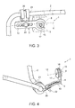
Figure 1 is a perspective that shows a preferred embodiment of the bracket connection device, particularly for fastening a component to the body in an engine compartment, according to the present invention; -
Figure 2 shows a variant of the device ofFigure 1 ; and -
Figures 3 and 4 show examples of application of the device ofFigure 1 . - In the attached figures, the
reference number 1 indicates a bracket connection device, used in particular for fastening a component to a body portion 3 (Figure 3 ) in an engine compartment of a motor vehicle. By way of example, thecomponent 2 is defined by a pipe, in particular forming part of an air conditioning system. - With reference to
Figure 1 , thedevice 1 comprises abracket 5, which is defined by a plate element, preferably of constant thickness, and is elongated along adirection 6, which is preferably straight (fig. 1 ). - The
bracket 5 is constituted by aneyelet portion 8, arranged at one end; and by anarm 10, which extends so as to protrude from theportion 8 along thedirection 6 and is made as a single piece with theportion 8. - With reference to
Figure 1 , theportion 8 has a throughseat 11, which extends along anaxis 12 perpendicular to thedirection 6; and anotch 13, which starts from theseat 11, radially extends and ends at the outer edge of theportion 8. Therefore, the inner edge of theportion 8, i.e. the contour of theseat 11, is not closed and continuous but is open at thenotch 13. - According to a variant not shown, the
notch 13 is absent, therefore theportion 8 is annular, i.e. the contour of theseat 11 is continuous, preferably circular. - The
device 1 also comprises acollar 15, which comprises an elastically deformable material, for example rubber or other elastomeric material, is supported by theportion 8 in a fixed position, engages theseat 11 and is coaxial with theseat 11. Preferably, thecollar 15 protrudes along theaxis 12 from both sides with respect to theportion 8. In particular, during assembly, thecollar 15 is inserted into theseat 11 by crushing and passing it radially through thenotch 13. When it exits from thenotch 13 into theseat 11, thecollar 15 takes back its original shape (complementary to that of the seat 11). In particular, thecollar 15 has an annular groove 16 (Fig. 4 ), which is made along the lateral surface and is engaged by the inner edge of theportion 8. - According to a variant not shown, the
collar 15 is over-molded onto the inner edge of theportion 8. - As shown in the attached figures, the
collar 15 defines anaxial passage 17, engaged by a connection element (not shown), e.g. a screw or stud, fastening thedevice 1 to thebody portion 3. Thecollar 15, thanks to properties of the material in which it is made, dampens the transmission of vibration between thebody portion 3 and thecomponent 2. - With reference to
Figure 1 , thearm 10 has a plurality of throughholes 18, whose axes are spaced apart along thedirection 6 and are orthogonal to thearm 10. Said axes, preferably, are aligned along thedirection 6. Advantageously, theholes 18 are at least three and are circular. - Advantageously, the
holes 18 all have the same diameter; and/or the pitch (or distance) between the axes of theholes 18 is constant. - In particular, at least part of the
holes 18 communicate with one another, i.e. the distance between the axes of twoconsecutive holes 18 is less than the sum of the two radii. This feature allows to bring theholes 18 closer to each other, i.e. to reduce the pitch, but without substantially altering the circular shape of the edge of theholes 18 themselves. - In the example of
Figure 1 , theholes 18 communicate with one another so as to form, together, a single slit 19. In the example ofFigure 2 , however, theholes 18 communicate with one another in pairs, and each pair is spaced apart from the next one, to avoid excessively reducing the stiffness and/or weakening too much thearm 10 of thebracket 5. - As shown in
figure 3 , thedevice 1 also comprises asupport element 20, which supports aportion 21 of thecomponent 2, is defined for example by a band wrapped around theportion 21 and is fixed to any one of theholes 18 by way of aconnection element 22 which extends axially through said hole. - The
connection element 22 can be defined by a deformable element, defining a snap coupling; by a pressure element, forming an interference coupling; or by a screw element, defining a threaded coupling. It is not excluded, however, that other types of coupling may be envisaged to exploit the possibility given by theholes 18 to adjust in a discrete way the position of thesupport element 20 with respect to theaxis 12. - The choice of which
hole 18 to use for fastening thesupport element 20 is made in the design step or directly in the assembly step, as a function of the available spaces and as a function of the distance between thecomponent 2 and thebody portion 3. Therefore, the row ofholes 18 gives the operator a degree of freedom for fastening the component to thesecond body portion 3. In other words, it is possible to use thedevice 1 in a wide range of situations, wherein the elements to be coupled are placed at different distances. - Advantageously, the
bracket 5 is flat. However, as shown inFigure 4 , thebracket 5 is made of a material and with a thickness such as to allow a user to bend and therefore deform it plastically, under construction, or during the installation and fastening of the components, in order to obtain a different shape than the flat one and, therefore, improve the adaptability of thedevice 1 to the available spaces. - From the foregoing it is evident how the
device 1 is substantially "modular", i.e. it can be used in different areas of the engine compartment and/or for fastening various components, as it has the possibility of joining elements arranged at different distances from one another, corresponding to the distance between theaxis 12 and the axis of thevarious holes 18 that can be chosen for the fastening. - Moreover, the
bracket 5 has a relatively simple shape to handle and use. In particular, during the connection between theconnection element 22 and theselected hole 18, the operator can rotate thebracket 5 aboutaxis 12 to search for the optimum angle with respect to thebody portion 3. - From the above it is, finally, evident that the described and illustrated
device 1 may be subject to modifications and variants which do not depart from the scope of protection of the present invention, as defined in the appended claims. - In particular, the distribution of the
holes 18 along thearm 10 may be different from that shown by way of example; and/or thedirection 6 may be curved; and/or theconnection element 22 could be attached directly to thecomponent 2, withoutsupport element 20.
Claims (10)
- A bracket connection device (1), particularly for fastening a component to the body in an engine compartment; the device comprising:- a bracket (5) defined by a plate element, elongated along a longitudinal direction (6), and comprising:characterized in that said arm has a plurality of holes (18) made along respective axes which are spaced apart from each other along said longitudinal direction (6); and by further comprising a collar (15) engaging said seat (11) and comprising elastically deformable material.a) an end portion (8) having a through seat (11);b) an arm (10), which extends so as to protrude from said end portion (8);
- The device according to claim 1, characterized in that said bracket (5) is made as a single piece.
- The device according to claim 1 or 2, characterized in that at least some of the holes (18) are aligned along said longitudinal direction (6).
- The device according to claim 3, characterized in that said at least some of the holes (18) communicate with one another.
- The device according to claim 4, characterized in that said holes (18) form pairs of holes, where each pair is spaced apart from the adjacent pair, and the holes of each pair communicate with one another.
- The device according to claim 4, characterized in that said holes (18) form, all together, a longitudinal slit (19).
- The device according to any one of claims 3 to 6, characterized in that said at least some of the holes (18) have respective axes arranged at a constant pitch.
- The device according to any one of the preceding claims, characterized in that said holes (18) have the same diameter.
- The device according to any one of the preceding claims, characterized in that said end portion (13) has a notch (13) which radially extends from one edge of said seat (11) to an outer edge of said end portion (8).
- The device according to any one of the preceding claims, characterized in that the arm (10) is made of a plastically deformable material.
Applications Claiming Priority (1)
| Application Number | Priority Date | Filing Date | Title |
|---|---|---|---|
| IT000185A ITTO20130185A1 (en) | 2013-03-08 | 2013-03-08 | BRACKET CONNECTION DEVICE, PARTICULARLY FOR FIXING COMPONENTS IN A ENGINE COMPARTMENT |
Publications (2)
| Publication Number | Publication Date |
|---|---|
| EP2774791A1 true EP2774791A1 (en) | 2014-09-10 |
| EP2774791B1 EP2774791B1 (en) | 2018-08-22 |
Family
ID=48366469
Family Applications (1)
| Application Number | Title | Priority Date | Filing Date |
|---|---|---|---|
| EP14158454.0A Active EP2774791B1 (en) | 2013-03-08 | 2014-03-07 | Bracket connection device, particularly for fastening components in an engine compartment |
Country Status (2)
| Country | Link |
|---|---|
| EP (1) | EP2774791B1 (en) |
| IT (1) | ITTO20130185A1 (en) |
Citations (6)
| Publication number | Priority date | Publication date | Assignee | Title |
|---|---|---|---|---|
| US4452418A (en) | 1980-09-12 | 1984-06-05 | Seiko Seiki Kabushiki Kaisha | Mounting structure for compressor for car cooler |
| FR2663354A1 (en) * | 1990-06-13 | 1991-12-20 | Abl Ind Sarl | Improved device for fixing facade facework stones |
| US20020157885A1 (en) * | 2001-04-30 | 2002-10-31 | Brown Daniel J. | Vehicle radiator support structure |
| US20050067548A1 (en) * | 2003-09-30 | 2005-03-31 | Tomoki Inoue | Bracket for fluid transport tube |
| US7506619B1 (en) * | 2007-10-12 | 2009-03-24 | Freudenberg-Nok General Partnership | Tunable hybrid bracket assembly |
| KR20100006973A (en) * | 2008-07-11 | 2010-01-22 | 한라공조주식회사 | Pipe bracket for automotive vehicles |
Family Cites Families (3)
| Publication number | Priority date | Publication date | Assignee | Title |
|---|---|---|---|---|
| US6070401A (en) * | 1998-08-28 | 2000-06-06 | Johnson; William A. | Grain saver dam |
| US6639760B2 (en) * | 2002-01-07 | 2003-10-28 | International Business Machines Corporation | Compliant worm gear and worm gear bracket |
| KR101091691B1 (en) * | 2009-06-18 | 2011-12-08 | 현대자동차주식회사 | Sliding apparatus of automobile cooling module |
-
2013
- 2013-03-08 IT IT000185A patent/ITTO20130185A1/en unknown
-
2014
- 2014-03-07 EP EP14158454.0A patent/EP2774791B1/en active Active
Patent Citations (6)
| Publication number | Priority date | Publication date | Assignee | Title |
|---|---|---|---|---|
| US4452418A (en) | 1980-09-12 | 1984-06-05 | Seiko Seiki Kabushiki Kaisha | Mounting structure for compressor for car cooler |
| FR2663354A1 (en) * | 1990-06-13 | 1991-12-20 | Abl Ind Sarl | Improved device for fixing facade facework stones |
| US20020157885A1 (en) * | 2001-04-30 | 2002-10-31 | Brown Daniel J. | Vehicle radiator support structure |
| US20050067548A1 (en) * | 2003-09-30 | 2005-03-31 | Tomoki Inoue | Bracket for fluid transport tube |
| US7506619B1 (en) * | 2007-10-12 | 2009-03-24 | Freudenberg-Nok General Partnership | Tunable hybrid bracket assembly |
| KR20100006973A (en) * | 2008-07-11 | 2010-01-22 | 한라공조주식회사 | Pipe bracket for automotive vehicles |
Also Published As
| Publication number | Publication date |
|---|---|
| ITTO20130185A1 (en) | 2014-09-09 |
| EP2774791B1 (en) | 2018-08-22 |
Similar Documents
| Publication | Publication Date | Title |
|---|---|---|
| US20050211847A1 (en) | Variable-duct support assembly | |
| US20070017591A1 (en) | Apparatus and method for shaping hose | |
| US20120124782A1 (en) | Fastening device | |
| US20130111721A1 (en) | Holder for an assembly of a vehicle | |
| US8992150B2 (en) | Device for connecting two components, holding means of such a device, and component | |
| JP2018516332A (en) | Thermal and vibration mounted isolator for heat shield, heat shield assembly and method of construction thereof | |
| CN203823287U (en) | Clamp element and clamp assembly for exhaust pipe system of internal combustion engine and exhaust pipe of internal combustion engine | |
| MX2014014118A (en) | Vehicle body mount. | |
| US10145290B2 (en) | Adjustable mount for an exhaust system and method for installing a mount for an exhaust system | |
| US8267799B2 (en) | Device for damping vibrations | |
| EP2774791B1 (en) | Bracket connection device, particularly for fastening components in an engine compartment | |
| CN110050144A (en) | Equipped with the air-conditioning pump of vibration damping component | |
| US10590828B2 (en) | Exhaust gas outlet system for a motor vehicle, motor vehicle having such an exhaust gas outlet system, and method for producing an exhaust gas outlet system | |
| CN108223223B (en) | Valve for metering a fluid | |
| EP2600475B1 (en) | Anti-rotation cable restraint for connecting flexible ducts | |
| US7628178B2 (en) | Safety device | |
| US8956069B2 (en) | Tool-free connector and mounting arrangement | |
| US10260659B2 (en) | Method for fastening a conduit on a support by means of freely adjustable captive flanges | |
| EP2213523B1 (en) | Fixing arrangement with self-centring elements for fixing an airbag module in an automotive vehicle | |
| US11680670B2 (en) | Coupling device for media-conducting lines | |
| US20120210706A1 (en) | Angled mounting plate for torque converter assembly | |
| EP3523561B1 (en) | A cable spacer arrangement | |
| CA2706248C (en) | Joint through a vehicle frame | |
| JP6126202B2 (en) | Bracket assembly for engine compartment parts | |
| CN112361581B (en) | Vibration reduction rubber part and air conditioner with same |
Legal Events
| Date | Code | Title | Description |
|---|---|---|---|
| PUAI | Public reference made under article 153(3) epc to a published international application that has entered the european phase |
Free format text: ORIGINAL CODE: 0009012 |
|
| 17P | Request for examination filed |
Effective date: 20140307 |
|
| AK | Designated contracting states |
Kind code of ref document: A1 Designated state(s): AL AT BE BG CH CY CZ DE DK EE ES FI FR GB GR HR HU IE IS IT LI LT LU LV MC MK MT NL NO PL PT RO RS SE SI SK SM TR |
|
| AX | Request for extension of the european patent |
Extension state: BA ME |
|
| R17P | Request for examination filed (corrected) |
Effective date: 20150227 |
|
| RBV | Designated contracting states (corrected) |
Designated state(s): AL AT BE BG CH CY CZ DE DK EE ES FI FR GB GR HR HU IE IS IT LI LT LU LV MC MK MT NL NO PL PT RO RS SE SI SK SM TR |
|
| GRAP | Despatch of communication of intention to grant a patent |
Free format text: ORIGINAL CODE: EPIDOSNIGR1 |
|
| STAA | Information on the status of an ep patent application or granted ep patent |
Free format text: STATUS: GRANT OF PATENT IS INTENDED |
|
| INTG | Intention to grant announced |
Effective date: 20180316 |
|
| GRAS | Grant fee paid |
Free format text: ORIGINAL CODE: EPIDOSNIGR3 |
|
| GRAA | (expected) grant |
Free format text: ORIGINAL CODE: 0009210 |
|
| STAA | Information on the status of an ep patent application or granted ep patent |
Free format text: STATUS: THE PATENT HAS BEEN GRANTED |
|
| AK | Designated contracting states |
Kind code of ref document: B1 Designated state(s): AL AT BE BG CH CY CZ DE DK EE ES FI FR GB GR HR HU IE IS IT LI LT LU LV MC MK MT NL NO PL PT RO RS SE SI SK SM TR |
|
| REG | Reference to a national code |
Ref country code: GB Ref legal event code: FG4D |
|
| REG | Reference to a national code |
Ref country code: CH Ref legal event code: EP |
|
| REG | Reference to a national code |
Ref country code: AT Ref legal event code: REF Ref document number: 1032032 Country of ref document: AT Kind code of ref document: T Effective date: 20180915 |
|
| REG | Reference to a national code |
Ref country code: IE Ref legal event code: FG4D |
|
| REG | Reference to a national code |
Ref country code: DE Ref legal event code: R096 Ref document number: 602014030720 Country of ref document: DE |
|
| REG | Reference to a national code |
Ref country code: NL Ref legal event code: MP Effective date: 20180822 |
|
| REG | Reference to a national code |
Ref country code: LT Ref legal event code: MG4D |
|
| PG25 | Lapsed in a contracting state [announced via postgrant information from national office to epo] |
Ref country code: FI Free format text: LAPSE BECAUSE OF FAILURE TO SUBMIT A TRANSLATION OF THE DESCRIPTION OR TO PAY THE FEE WITHIN THE PRESCRIBED TIME-LIMIT Effective date: 20180822 Ref country code: IS Free format text: LAPSE BECAUSE OF FAILURE TO SUBMIT A TRANSLATION OF THE DESCRIPTION OR TO PAY THE FEE WITHIN THE PRESCRIBED TIME-LIMIT Effective date: 20181222 Ref country code: NO Free format text: LAPSE BECAUSE OF FAILURE TO SUBMIT A TRANSLATION OF THE DESCRIPTION OR TO PAY THE FEE WITHIN THE PRESCRIBED TIME-LIMIT Effective date: 20181122 Ref country code: BG Free format text: LAPSE BECAUSE OF FAILURE TO SUBMIT A TRANSLATION OF THE DESCRIPTION OR TO PAY THE FEE WITHIN THE PRESCRIBED TIME-LIMIT Effective date: 20181122 Ref country code: SE Free format text: LAPSE BECAUSE OF FAILURE TO SUBMIT A TRANSLATION OF THE DESCRIPTION OR TO PAY THE FEE WITHIN THE PRESCRIBED TIME-LIMIT Effective date: 20180822 Ref country code: GR Free format text: LAPSE BECAUSE OF FAILURE TO SUBMIT A TRANSLATION OF THE DESCRIPTION OR TO PAY THE FEE WITHIN THE PRESCRIBED TIME-LIMIT Effective date: 20181123 Ref country code: RS Free format text: LAPSE BECAUSE OF FAILURE TO SUBMIT A TRANSLATION OF THE DESCRIPTION OR TO PAY THE FEE WITHIN THE PRESCRIBED TIME-LIMIT Effective date: 20180822 Ref country code: NL Free format text: LAPSE BECAUSE OF FAILURE TO SUBMIT A TRANSLATION OF THE DESCRIPTION OR TO PAY THE FEE WITHIN THE PRESCRIBED TIME-LIMIT Effective date: 20180822 Ref country code: LT Free format text: LAPSE BECAUSE OF FAILURE TO SUBMIT A TRANSLATION OF THE DESCRIPTION OR TO PAY THE FEE WITHIN THE PRESCRIBED TIME-LIMIT Effective date: 20180822 |
|
| PG25 | Lapsed in a contracting state [announced via postgrant information from national office to epo] |
Ref country code: AL Free format text: LAPSE BECAUSE OF FAILURE TO SUBMIT A TRANSLATION OF THE DESCRIPTION OR TO PAY THE FEE WITHIN THE PRESCRIBED TIME-LIMIT Effective date: 20180822 Ref country code: LV Free format text: LAPSE BECAUSE OF FAILURE TO SUBMIT A TRANSLATION OF THE DESCRIPTION OR TO PAY THE FEE WITHIN THE PRESCRIBED TIME-LIMIT Effective date: 20180822 Ref country code: HR Free format text: LAPSE BECAUSE OF FAILURE TO SUBMIT A TRANSLATION OF THE DESCRIPTION OR TO PAY THE FEE WITHIN THE PRESCRIBED TIME-LIMIT Effective date: 20180822 |
|
| PG25 | Lapsed in a contracting state [announced via postgrant information from national office to epo] |
Ref country code: ES Free format text: LAPSE BECAUSE OF FAILURE TO SUBMIT A TRANSLATION OF THE DESCRIPTION OR TO PAY THE FEE WITHIN THE PRESCRIBED TIME-LIMIT Effective date: 20180822 Ref country code: PL Free format text: LAPSE BECAUSE OF FAILURE TO SUBMIT A TRANSLATION OF THE DESCRIPTION OR TO PAY THE FEE WITHIN THE PRESCRIBED TIME-LIMIT Effective date: 20180822 Ref country code: RO Free format text: LAPSE BECAUSE OF FAILURE TO SUBMIT A TRANSLATION OF THE DESCRIPTION OR TO PAY THE FEE WITHIN THE PRESCRIBED TIME-LIMIT Effective date: 20180822 Ref country code: CZ Free format text: LAPSE BECAUSE OF FAILURE TO SUBMIT A TRANSLATION OF THE DESCRIPTION OR TO PAY THE FEE WITHIN THE PRESCRIBED TIME-LIMIT Effective date: 20180822 Ref country code: IT Free format text: LAPSE BECAUSE OF FAILURE TO SUBMIT A TRANSLATION OF THE DESCRIPTION OR TO PAY THE FEE WITHIN THE PRESCRIBED TIME-LIMIT Effective date: 20180822 Ref country code: EE Free format text: LAPSE BECAUSE OF FAILURE TO SUBMIT A TRANSLATION OF THE DESCRIPTION OR TO PAY THE FEE WITHIN THE PRESCRIBED TIME-LIMIT Effective date: 20180822 |
|
| REG | Reference to a national code |
Ref country code: DE Ref legal event code: R097 Ref document number: 602014030720 Country of ref document: DE |
|
| PG25 | Lapsed in a contracting state [announced via postgrant information from national office to epo] |
Ref country code: DK Free format text: LAPSE BECAUSE OF FAILURE TO SUBMIT A TRANSLATION OF THE DESCRIPTION OR TO PAY THE FEE WITHIN THE PRESCRIBED TIME-LIMIT Effective date: 20180822 Ref country code: SM Free format text: LAPSE BECAUSE OF FAILURE TO SUBMIT A TRANSLATION OF THE DESCRIPTION OR TO PAY THE FEE WITHIN THE PRESCRIBED TIME-LIMIT Effective date: 20180822 Ref country code: SK Free format text: LAPSE BECAUSE OF FAILURE TO SUBMIT A TRANSLATION OF THE DESCRIPTION OR TO PAY THE FEE WITHIN THE PRESCRIBED TIME-LIMIT Effective date: 20180822 |
|
| PLBE | No opposition filed within time limit |
Free format text: ORIGINAL CODE: 0009261 |
|
| STAA | Information on the status of an ep patent application or granted ep patent |
Free format text: STATUS: NO OPPOSITION FILED WITHIN TIME LIMIT |
|
| 26N | No opposition filed |
Effective date: 20190523 |
|
| PG25 | Lapsed in a contracting state [announced via postgrant information from national office to epo] |
Ref country code: SI Free format text: LAPSE BECAUSE OF FAILURE TO SUBMIT A TRANSLATION OF THE DESCRIPTION OR TO PAY THE FEE WITHIN THE PRESCRIBED TIME-LIMIT Effective date: 20180822 |
|
| PG25 | Lapsed in a contracting state [announced via postgrant information from national office to epo] |
Ref country code: MC Free format text: LAPSE BECAUSE OF FAILURE TO SUBMIT A TRANSLATION OF THE DESCRIPTION OR TO PAY THE FEE WITHIN THE PRESCRIBED TIME-LIMIT Effective date: 20180822 |
|
| REG | Reference to a national code |
Ref country code: CH Ref legal event code: PL |
|
| GBPC | Gb: european patent ceased through non-payment of renewal fee |
Effective date: 20190307 |
|
| PG25 | Lapsed in a contracting state [announced via postgrant information from national office to epo] |
Ref country code: LU Free format text: LAPSE BECAUSE OF NON-PAYMENT OF DUE FEES Effective date: 20190307 |
|
| REG | Reference to a national code |
Ref country code: BE Ref legal event code: MM Effective date: 20190331 |
|
| PG25 | Lapsed in a contracting state [announced via postgrant information from national office to epo] |
Ref country code: LI Free format text: LAPSE BECAUSE OF NON-PAYMENT OF DUE FEES Effective date: 20190331 Ref country code: GB Free format text: LAPSE BECAUSE OF NON-PAYMENT OF DUE FEES Effective date: 20190307 Ref country code: IE Free format text: LAPSE BECAUSE OF NON-PAYMENT OF DUE FEES Effective date: 20190307 Ref country code: CH Free format text: LAPSE BECAUSE OF NON-PAYMENT OF DUE FEES Effective date: 20190331 |
|
| PG25 | Lapsed in a contracting state [announced via postgrant information from national office to epo] |
Ref country code: BE Free format text: LAPSE BECAUSE OF NON-PAYMENT OF DUE FEES Effective date: 20190331 |
|
| PG25 | Lapsed in a contracting state [announced via postgrant information from national office to epo] |
Ref country code: TR Free format text: LAPSE BECAUSE OF FAILURE TO SUBMIT A TRANSLATION OF THE DESCRIPTION OR TO PAY THE FEE WITHIN THE PRESCRIBED TIME-LIMIT Effective date: 20180822 |
|
| PG25 | Lapsed in a contracting state [announced via postgrant information from national office to epo] |
Ref country code: PT Free format text: LAPSE BECAUSE OF FAILURE TO SUBMIT A TRANSLATION OF THE DESCRIPTION OR TO PAY THE FEE WITHIN THE PRESCRIBED TIME-LIMIT Effective date: 20181222 Ref country code: MT Free format text: LAPSE BECAUSE OF NON-PAYMENT OF DUE FEES Effective date: 20190307 |
|
| REG | Reference to a national code |
Ref country code: AT Ref legal event code: MM01 Ref document number: 1032032 Country of ref document: AT Kind code of ref document: T Effective date: 20190307 |
|
| PG25 | Lapsed in a contracting state [announced via postgrant information from national office to epo] |
Ref country code: AT Free format text: LAPSE BECAUSE OF NON-PAYMENT OF DUE FEES Effective date: 20190307 |
|
| PG25 | Lapsed in a contracting state [announced via postgrant information from national office to epo] |
Ref country code: CY Free format text: LAPSE BECAUSE OF FAILURE TO SUBMIT A TRANSLATION OF THE DESCRIPTION OR TO PAY THE FEE WITHIN THE PRESCRIBED TIME-LIMIT Effective date: 20180822 |
|
| PG25 | Lapsed in a contracting state [announced via postgrant information from national office to epo] |
Ref country code: HU Free format text: LAPSE BECAUSE OF FAILURE TO SUBMIT A TRANSLATION OF THE DESCRIPTION OR TO PAY THE FEE WITHIN THE PRESCRIBED TIME-LIMIT; INVALID AB INITIO Effective date: 20140307 |
|
| PG25 | Lapsed in a contracting state [announced via postgrant information from national office to epo] |
Ref country code: MK Free format text: LAPSE BECAUSE OF FAILURE TO SUBMIT A TRANSLATION OF THE DESCRIPTION OR TO PAY THE FEE WITHIN THE PRESCRIBED TIME-LIMIT Effective date: 20180822 |
|
| PGFP | Annual fee paid to national office [announced via postgrant information from national office to epo] |
Ref country code: FR Payment date: 20230222 Year of fee payment: 10 |
|
| PGFP | Annual fee paid to national office [announced via postgrant information from national office to epo] |
Ref country code: DE Payment date: 20230221 Year of fee payment: 10 |
|
| PGFP | Annual fee paid to national office [announced via postgrant information from national office to epo] |
Ref country code: DE Payment date: 20240220 Year of fee payment: 11 |