EP2774701A1 - Vacuum or air casting using induction hot topping - Google Patents
Vacuum or air casting using induction hot topping Download PDFInfo
- Publication number
- EP2774701A1 EP2774701A1 EP14155447.7A EP14155447A EP2774701A1 EP 2774701 A1 EP2774701 A1 EP 2774701A1 EP 14155447 A EP14155447 A EP 14155447A EP 2774701 A1 EP2774701 A1 EP 2774701A1
- Authority
- EP
- European Patent Office
- Prior art keywords
- mold
- melt
- metallic material
- molten
- reservoir
- Prior art date
- Legal status (The legal status is an assumption and is not a legal conclusion. Google has not performed a legal analysis and makes no representation as to the accuracy of the status listed.)
- Withdrawn
Links
Images


Classifications
-
- B—PERFORMING OPERATIONS; TRANSPORTING
- B22—CASTING; POWDER METALLURGY
- B22D—CASTING OF METALS; CASTING OF OTHER SUBSTANCES BY THE SAME PROCESSES OR DEVICES
- B22D25/00—Special casting characterised by the nature of the product
-
- B—PERFORMING OPERATIONS; TRANSPORTING
- B22—CASTING; POWDER METALLURGY
- B22D—CASTING OF METALS; CASTING OF OTHER SUBSTANCES BY THE SAME PROCESSES OR DEVICES
- B22D18/00—Pressure casting; Vacuum casting
- B22D18/06—Vacuum casting, i.e. making use of vacuum to fill the mould
-
- B—PERFORMING OPERATIONS; TRANSPORTING
- B22—CASTING; POWDER METALLURGY
- B22D—CASTING OF METALS; CASTING OF OTHER SUBSTANCES BY THE SAME PROCESSES OR DEVICES
- B22D21/00—Casting non-ferrous metals or metallic compounds so far as their metallurgical properties are of importance for the casting procedure; Selection of compositions therefor
- B22D21/02—Casting exceedingly oxidisable non-ferrous metals, e.g. in inert atmosphere
- B22D21/025—Casting heavy metals with high melting point, i.e. 1000 - 1600 degrees C, e.g. Co 1490 degrees C, Ni 1450 degrees C, Mn 1240 degrees C, Cu 1083 degrees C
-
- B—PERFORMING OPERATIONS; TRANSPORTING
- B22—CASTING; POWDER METALLURGY
- B22D—CASTING OF METALS; CASTING OF OTHER SUBSTANCES BY THE SAME PROCESSES OR DEVICES
- B22D27/00—Treating the metal in the mould while it is molten or ductile ; Pressure or vacuum casting
- B22D27/04—Influencing the temperature of the metal, e.g. by heating or cooling the mould
-
- B—PERFORMING OPERATIONS; TRANSPORTING
- B22—CASTING; POWDER METALLURGY
- B22D—CASTING OF METALS; CASTING OF OTHER SUBSTANCES BY THE SAME PROCESSES OR DEVICES
- B22D27/00—Treating the metal in the mould while it is molten or ductile ; Pressure or vacuum casting
- B22D27/15—Treating the metal in the mould while it is molten or ductile ; Pressure or vacuum casting by using vacuum
-
- B—PERFORMING OPERATIONS; TRANSPORTING
- B22—CASTING; POWDER METALLURGY
- B22C—FOUNDRY MOULDING
- B22C9/00—Moulds or cores; Moulding processes
- B22C9/02—Sand moulds or like moulds for shaped castings
- B22C9/04—Use of lost patterns
-
- B—PERFORMING OPERATIONS; TRANSPORTING
- B22—CASTING; POWDER METALLURGY
- B22C—FOUNDRY MOULDING
- B22C9/00—Moulds or cores; Moulding processes
- B22C9/08—Features with respect to supply of molten metal, e.g. ingates, circular gates, skim gates
- B22C9/086—Filters
Definitions
- the invention relates to a method for the vacuum or air casting of molten metallic material, such as for example, nickel or cobalt base superalloys, stainless steels, and the like in a preheated mold to make an improved cast part.
- molten metallic material such as for example, nickel or cobalt base superalloys, stainless steels, and the like
- Nickel base or cobalt base superalloys have been cast in investment molds in vacuum or air and then are moved to cool in air where exothermic material hot topping is applied to the mold pour cup to produce certain equiaxed grain cast gas turbine blades that are free of solidification shrinkage defects.
- exothermic material such as aluminum-containing powder material
- prior art workers have placed exothermic material, such as aluminum-containing powder material, on the molten superalloy reservoir remaining in the pour cup of the investment mold to keep molten after the mold is filled with molten superalloy and as solidification occurs in order to counter solidification shrinkage in the cast blade.
- This casting practice in air using such exothermic material is disadvantageous for several reasons that include, but are not limited to, occurrence of severe reactions (flash and burning) of the exothermic material upon contact with the molten superalloy in the mold pour cup as well as the need to safely remove the smoke and vapors from the containment area. Exposing a hot casting to air also promotes the formation of unwanted hafnum oxides as surface scale at last-to-solidify regions of the cast blade, such as the blade root when cast in the tip- down orientation. In addition, contamination of the superalloy material remaining in the pour cup from the reaction with the exothermic material occurs to such an extent that the contaminated pour cup material cannot be reused as revert (recycled) material in the casting of another part.
- exothermic material is described in US 6,446,698 wherein a modified mold is used for casting molten metal or alloy.
- the mold is modified to have a destructible extension between the mold pour cup and a reservoir above the mold cavity and through which extension exothermic material is introduced and placed on the surface of the molten metal or alloy in the reservoir.
- US Patent 3,841, 384 describes a casting process sans exothermic material wherein an upper/lower split induction coil is used to heat a crucible placed on top of a mold to be cast. One of the coils is energized to first heat the crucible to melt a solid metal or alloy charge therein and then both coils are energized to impart superheat to the melt in the crucible and to preheat the mold for casting to receive molten metal or alloy from the crucible.
- US Patents 5, 592, 984 ; 6,019,158 ; and 6,640,877 describe casting methods sans exothermic material for reducing shrinkage defects upon solidification of molten metal or alloy in a preheated mold by pressurizing the casting chamber or by placing a pressurizing cap on the mold after it is filled with molten metal. The entire mold is preheated prior to casting with no further mold heating.
- US Patent 4,832,112 discloses the MX casting process sans exothermic material wherein a molten metal or alloy with controlled low superheat is cast into a mold and subjected to electromagnetic stirring to induce turbulence in the molten metal or alloy in the mold without substantial heating thereof.
- the present invention provides a method and apparatus for casting a molten metallic material under vacuum or in ambient air sans exothermic material to form a cast part that is free of shrinkage defects.
- the method and apparatus involve introducing molten metallic material (melt) into a preheated mold wherein the mold has a melt reservoir, such as a pour cup, and gating that feeds the melt to one or more mold cavities. Excess melt is provided in the melt reservoir, such as the pour cup, and the gating for feeding to the one or more mold cavities during solidification there.
- An induction coil is disposed locally adjacent to the melt reservoir and is energized in a manner to locally heat the excess melt in the melt reservoir to maintain it molten as the molten metallic material solidifies in the one or more mold cavities of the preheated mold. The excess molten metallic material is fed as needed to eliminate shrinkage defects as solidification proceeds in the mold cavity.
- the preheated mold and the induction coil are relatively moved in a vacuum chamber or in air so that the induction coil resides locally around the melt reservoir prior to introduction of the molten metallic material into the preheated mold.
- the induction coil is energized to locally heat the excess molten metallic material in the melt reservoir to maintain it molten without substantially heating the region of the mold in which the one or more mold cavities reside.
- a particular illustrative embodiment of the invention involves vacuum casting a molten superalloy containing an oxygen-reactive alloying element (alloyant) (e. g. hafnium, zirconium, titanium, aluminum, etc.) wherein molten superalloy is introduced into a mold pour cup (or other reservoir) and gating of a preheated ceramic investment mold residing in a vacuum chamber at less than 0.020 mm Hg so as to fill a mold cavity with the molten superalloy and wherein an induction coil disposed locally around the melt pour cup (or other reservoir) is energized to locally heat the excess molten superalloy remaining in the melt reservoir to maintain it molten as the superalloy solidifies under vacuum in the mold cavity of the preheated mold to produce an equaixed grain, superalloy cast part without shrinkage defects and without the presence of a hafnium or other reactive element oxide scale.
- the mold cavity can have the shape of a gas turbine blade, van
- the present invention provides an apparatus for vacuum casting of a molten metallic material, wherein the apparatus includes a vacuum casting chamber that receives a preheated mold having a melt reservoir and gating communicated to a mold cavity to fill the mold cavity with the molten metallic material from the reservoir and further includes an induction coil disposed locally adjacent to the melt reservoir and energizable by a power source in a manner to locally heat the excess molten metallic material in the melt reservoir to maintain it molten as the molten metallic material solidifies under vacuum in the mold cavity of the preheated mold.
- the vacuum casting chamber is communicated to a mold preheating chamber when a valve therebetween is opened pursuant to a particular embodiment of the invention.
- the induction coil and the preheated mold are relatively movable to position the induction coil locally around the melt pour cup (or other reservoir).
- a molten metal or alloy filter may optionally be provided in the pour cup, reservoir, and/or gating.
- the method and apparatus involve introducing molten metallic material (melt) into a preheated mold in ambient air (atmospheric air) wherein the mold has a melt reservoir, such as a pour cup, and gating that feeds the melt to one or more mold cavities.
- molten metallic material is provided in the melt reservoir, such as the pour cup, and the gating for feeding to the one or more mold cavities during solidification there.
- An induction coil is disposed locally adjacent to the melt reservoir and is energized in a manner to locally heat the excess melt in the melt reservoir to maintain it molten as the molten metallic material solidifies in air in the one or more mold cavities of the preheated mold.
- the excess molten metallic material is fed as needed to eliminate shrinkage defects as solidification proceeds in air in the mold cavity.
- Practice of the present invention is advantageous to avoid occurrence of severe reactions (flash and burning) associated with previously-used exothermic material placed on the melt in the mold pour cup, to avoid contamination of solidified metallic material remaining in the mold pour cup after solidification so that it can be reused, to avoid shrinkage defects in the cast part, and to avoid the formation of unwanted reactive element oxides as surface scale at last-to-solidify regions of the cast part when certain superalloys are cast.
- One illustrative embodiment of the invention relates to the vacuum casting of molten metallic material in a preheated mold in a vacuum casting chamber under conditions that reduce or eliminate shrinkage defects in the cast part and unwanted oxide surface scale on the cast parts. Moreover, the vacuum casting method is conducted under conditions that avoid contamination of solidified metallic material remaining in the mold pour cup (or other reservoir) after solidification so that it can be reused as revert in the casting another cast part.
- FIGS 1-5 show apparatus pursuant to an illustrative embodiment of the invention for vacuum melting and casting a metallic material pursuant to illustrative embodiments of the invention.
- Metallic materials which can be vacuum melted and cast include, but are not limited to, metals, metal alloys, intermetallic compounds, and other metallic materials.
- the method and apparatus will be described in connection with the vacuum melting and vacuum casting of a nickel base superalloy (or cobalt base superalloy) of the types used in the manufacture of gas turbine components, such as turbine blades, turbine vanes, turbine buckets and other components.
- Such nickel base superalloys and cobalt base superalloys are well known and include, but are not limited to, Mar-M 247 and Rene 80.
- the invention is especially useful in the vacuum casting of nickel base or cobalt base superalloys that contain oxygen-reactive alloying elements, such as hafnium (Hf), zirconium (Zr), titanium (Ti) aluminum, etc. that, when cast in air, form unwanted oxide scales (e. g. hafnium oxide) on last-to-solidify or other regions of the cast part.
- oxygen-reactive alloying elements such as hafnium (Hf), zirconium (Zr), titanium (Ti) aluminum, etc. that, when cast in air, form unwanted oxide scales (e. g. hafnium oxide) on last-to-solidify or other regions of the cast part.
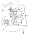
- the illustrative apparatus comprises upper vacuum casting chamber 10 and a lower mold-receiving chamber 12 communicated to one another by a movable (e.g. slidable) valve 14 residing on intermediate chamber wall W for opening and closing the opening OP through which mold M moves between chambers 10, 12.
- a movable (e.g. slidable) valve 14 residing on intermediate chamber wall W for opening and closing the opening OP through which mold M moves between chambers 10, 12.
- the upper vacuum casting chamber 10 is maintained under a vacuum (subambient pressure), such as less than about 0.020 mm Hg and preferably less than 0.001 mm Hg when a nickel base or cobalt base superalloy is being melted and cast in the preheated mold in the chamber 10.
- the lower mold-receiving chamber 12 typically is maintained at the same vacuum level as chamber 10 once the preheated mold is received in the chamber 12.
- the mold M is preheated in a separate external mold preheat furnace (not shown) that can be gas-fired, electrical or other type.
- the preheated mold M then is moved from the preheating furnace into the mold- receiving chamber 12.
- the mold M is manually or robotically moved into chamber 12 through a gas-tight sealable door 32 that opens to ambient air atmosphere.
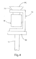
- the preheated mold M can be positioned in chamber 12 onto a mold-locating fixture or stand 72 residing on a lift or elevator 50, Figure 4 .
- the elevator 50 is raised or lowered via a ram 51 and ram actuator 53, such as a hydraulic, electrical or other motor, located outside or inside chamber 12.
- a relative vacuum typically is established in the chamber 12 by one or more suitable vacuum pump(s) 61.
- the lower mold-receiving chamber 12 optionally may include conventional electrical resistance heating coil(s) or other heating device to preheat or supplement preheating the mold thereto by a valved opening OP2 similar to opening OP between the chambers 10, 12 that is closed/opened by valve 14.
- a valved opening OP2 similar to opening OP between the chambers 10, 12 that is closed/opened by valve 14.
- the chamber 16 can be evacuated by one or more suitable vacuum pumps 65 so that the solid charge to be melted can be lowered from chamber 16 into the crucible 30 in evacuated chamber 10 by a hoist or other transfer device residing in chamber 16.
- the crucible 30 is mounted on movable door 32 that opens to the ambient air atmosphere to permit a preheated mold M to be placed on the elevator 50 in the chamber 12.
- the door 32 is movable to a closed, gas-tight sealed position forming a wall or wall portion of the chambers 10, 12 so that the desired vacuum level can be established in the chambers 10, 12 by the vacuum pump(s) 61.
- a vacuum level of less than 20 microns-Hg ( ⁇ m-Hg) is typically established in the chamber 10 and chamber 12.
- the crucible 30 When the door 32 is closed and vacuum-tight sealed, the crucible 30 is positioned above a vacuum induction hot topping induction coil (VIHT coil) 40 mounted on one or more support plates 41 that, in turn, are supported on a first cross support frame 42.
- the cross frame 42 is adjustably mounted on the top rails of the second support frame 44, which includes adjustment holes 45 so that the position of the VIHT coil 40 can be initially adjusted relative to the position of the melt stream poured from the crucible 30 into the mold M.
- the second frame 44 is mounted on the intermediate wall W disposed between the mold preheating chamber 12 and the vacuum casting chamber 10.
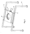
- the VIHT coil 40 comprises a water-cooled copper tubing coil faced on its inner surface with a ceramic grout material such as a zircon, alumina, silica, or a mixture thereof to protect the tubing coil from the heat of the melt stream discharged from the crucible 30.
- the coil 40 includes suitable fittings F to connect to cooling water conduits represented by arrows in Figure 5 .
- Electrical power is supplied to the coil 40 by electrical power wires shown schematically as lines L, in Figure 2 , from an external power source S, such as an Inductotherm Vacuum Induction power source, mounted on the exterior of the adjacent wall of the vacuum casting chamber 10 or other suitable location.
- an external power source S such as an Inductotherm Vacuum Induction power source, mounted on the exterior of the adjacent wall of the vacuum casting chamber 10 or other suitable location.
- the mold M is illustrated as a ceramic investment shell mold having a pour cup PC (melt reservoir) communicated by gating G to dual mold cavities MC1, MC2 residing within respective mold cavity-forming mold regions R1, R2 of the mold.
- the mold cavities MC1, MC2 can have the shape of a gas turbine engine blade to be cast, although the mold cavities can have any other shape corresponding to the cast part to be made.
- the ceramic investment shell mold is formed as one-piece by the well known lost wax investment molding process. The invention, however, envisions using other types of molds such as including, but not limited to, machined refractory metal or ceramic molds, or preformed ceramic molds.
- Figures 1-4 show the mold M as having an integral upper pour cup PC to function as the melt reservoir, the invention envisions use of other types of molds having an internal melt reservoir or of molds having a melt reservoir separate from the mold yet communicated to the mold cavities to provide excess melt therein for feeding to the mold cavities during solidification to eliminate shrinkage defects in the cast part.
- the mold pour cup PC of the preheated mold M is illustrated as being initially positioned on locating tubes 71 of the mold-locating fixture or stand 72 that is fixedly mounted on the elevator 50 in the chamber 12. The elevator 50 then is raised to position the preheated mold to the casting position shown in Figures 1 and 2 in vacuum chamber 10.
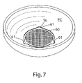
- a molten metal filter 60 may be placed in the pour cup PC, as shown in Figure 7 to remove dross and other contaminants from the melt stream before its enters the mold cavites MC1, MC2 .
- the filter 60 includes locking tabs 61 that enter and engage in respective slots SL in the pour cup PC to lock the filter in position.
- the filter alternately, or in addition, can be placed in the gating G of the mold.
- the mold M is preheated in the separate mold preheating furnace while the mold is held in a pour cup-down position.
- the preheated mold is inverted and placed on the locating tubes 71 of mold-locating fixture or stand 72 that resides on the elevator 50 in the chamber 12.
- the door 32 is closed and sealed gastight.
- the chamber 12 then typically is evacuated to the same vacuum level as chamber 10, and then the valve 14 is opened and the preheated mold M on fixture or stand 72 is raised using the elevator 50 to the casting position where the pour cup PC is positioned within and locally adjacent to the VIHT coil 40 and beneath the crucible 30 where the pour cup PC can receive the poured melt stream from the crucible 30.
- the solid charge in the crucible 30 can be melted under vacuum in chamber 10 before or after the preheated mold M is raised to the casting position.
- the mold M is preheated outside the chambers 10, 12 and transported onto the fixture or stand 72 on the elevator 50 in chamber 12 concurrent with the melting of the solid charge in the crucible 30 under vacuum in chamber 10.
- the crucible 30 then is rotated to introduce (pour) the superalloy melt into the pour cup PC (melt reservoir) and gating G of preheated mold M residing in a vacuum chamber 10 so as to fill a mold cavities MC1, MC2 with the superalloy melt via the pour cup PC and gating G.
- the superalloy melt is introduced into the superalloy melt and to leave excess superalloy melt in the pour cup PC as a melt reservoir and in the gating G above the mold cavities.
- the VIHT coil 40 is energized by power source S to locally heat the superalloy melt remaining in the pour cup PC and adjacent gating G if needed to maintain it molten as the superalloy melt solidifies under vacuum in the mold cavities MC1, MC2 of the preheated mold M in chamber 10.
- the electromagnetic field of the coil 40 couples to the excess superalloy melt remaining in the pour cup to locally heat the excess melt in the pour cup and adjacent gating without substantially heating the regions R1, R2 of the mold in which the mold cavities reside.
- the coil 40 typically is energized until the superalloy melt solidifies completely in the mold cavities MC1, MC2 and then the power is reduced to allow the alloy in the resevoir (pour cup) to solidify prior to removing from the vacuum furnace.
- the inner diameter and height (number of coil turns) of the coil 40 and as well as the spacing of the VIHT coil 40 relative to the mold pour cup PC and the level of coil energization is/are selected in dependence on the dimensions of the mold pour cup PC and amount of excess superalloy melt therein so that the coil's electromagnetic field couples with the excess superalloy melt in the pour cup to locally heat it as the superalloy melt solidifies in the mold cavities.
- the induction coil 40 is designed to maximize coupling with the excess superalloy in the pour cup PC by minimizing the distance from the molten alloy to the coil. Typically the distance ranges from 2-4 inches but may be more or less depending on specific component geometries. Further a minimum of energy is used to maintain the alloy in the pour cup PC in a molten state. This energy may be varied during operation in order to allow the alloy in the pour cup to freeze over providing for a minimum of oxides and nitrides in the residual alloy in the pour cup. This ensures it will be suitable for re-use. It is also advantageous to time the freezing of the alloy in the pour cup to the end of solidification in the casting so that the mold is removed from the casting chamber 10 and lower chamber 12 in time to allow another mold to be loaded in time to pour without adversely affecting cycle time.
- the superalloy melt solidifies under vacuum in the mold cavities MC1, MC2 over time to produce an equaixed grain, superalloy cast part without shrinkage defects and without the presence of a reactive element oxide scale resulting from oxidation of a reactive element of the superalloy, such as hafnium present in certain nickel base superalloys.
- the rate of solidification in chamber 10 can be increased by introducing an inert thermally conductive cooling gas, such as argon, into the chamber 10 for a period of time after the superalloy melt is poured into the preheated mold M.
- valve 14 can be opened, and the cast mold lowered into chamber 12 using the mold elevator 50 where it can be cooled to ambient temperature inside the chamber 12, or it can be removed outside of the chamber 12 to finish cooling in ambient air.
- VIHT coils 40, 40', 40" can be provided on support plate 41' of supports 42', 44' in the event the mold M includes multiple pour cups or other reservoirs, such as might be used to cast a larger gas turbine engine vane. Design and operation of the coils 40, 40', 40" involve the same features as described above for the single VIHT coil 40.
- Practice of the present invention is advantageous to avoid occurrence of severe reactions (flash and burning) associated with previously-used exothermic material placed on the melt in the mold pour cup, to avoid contamination of solidified metallic material remaining in the mold pour cup after solidification so that it can be reused, to avoid shrinkage defects in the cast part, and to avoid the formation of unwanted reactive element oxides as surface scale at last-to-solidify regions of the cast part when certain superalloys are cast.
- An equiaxed grain gas turbine engine blade having a length of 26 inches and weight of 23 pounds was vacuum cast from a Mar-M 2 47 nickel base superalloy using apparatus similar to that described above and shown in Figures 1-5 .
- the mold preheat temperature was 2200°F.
- the superalloy pour temperature was 2705°F using a melting cycle time in the crucible of about 25 minutes.
- the superalloy melt pour time into the mold was about 10 seconds.
- the VIHT coil was 8 inches in inner diameter with 4 coil turns.
- the inner surface of the VIHT oil was faced with a alumina, silica, zircon grout ceramic layer applied by hand and formed by mandrel.
- the inner surface of the VIHT coil was spaced 0.5 inch from the largest diameter of the pour cup.
- the VIHT coil was energized immediately after pouring the molten alloy into the mold and at a power level of 90 kW for 10 minutes. Then power was gradually reduced to 0 kW until alloy in the pour cup froze.
- the total VIHT cycle time is about 20 minutes. After the alloy in the pour cup was solidified the mold was lowered into the lower mold chamber 12 and removed to finish cooling in air.
- the vacuum level in the vacuum casting chamber at pour was 15 ⁇ m-Hg.
- the cast blade had an equiaxed grain microstructure and was free of shrinkage defects and hafnium oxide scale at the last-to-solidify root region of the cast blade. Moreover, the solidified superalloy in the pour cup was closed and free of oxide contamination so that it could be reused as revert to cast another part.
- Another illustrative embodiment of the invention is useful, although not limited to, casting of stainless steel (or other metals or alloys) in air.
- stainless steels include, but are not limited to, ferritic, austenitic and PH (precipitation hardening) stainless steels.
- the method and apparatus involve introducing molten metallic material (melt) into a preheated mold in ambient air (atmospheric air) wherein the mold has a melt reservoir, such as a pour cup, and gating that feed the melt to one or more mold cavities. Excess melt is provided in the melt reservoir, such as the pour cup, and the gating for feeding to the one or more mold cavities during solidification there.
- An induction coil like coil 40 is disposed locally adjacent to the melt reservoir and is energized in a manner to locally heat the excess melt in the melt reservoir to maintain it molten as the molten metallic material solidifies in air in the one or more mold cavities of the preheated mold.
- the excess molten metallic material is fed as needed to eliminate shrinkage defects as solidification proceeds in air in the mold cavity.
- the chambers 10, 12 described above simply can be left open to ambient air (atmospheric air pressure) during the sequence of steps described above for casting a stainless steel melt into the preheated mold.
- the chambers 10, 12 can be dispensed with such that a preheated mold can be moved to position its pour cup in a VIHT coil of the type shown as "40" in Figure 5 and cast in air using a crucible of the type shown as "30" in Figures 1 and 2 containing the stainless steel melt located above the mold pour cup in air.
- the VIHT coil could be supported on a support plate and supports like those shown in Figure 5 .
- the induction coil is energized to locally heat the molten metallic material in the reservoir and the gating adjacent to the reservoir without substantially heating the region of the mold in which the one or more mold cavities reside.
- the melt reservoir is a mold pour cup disposed above the mold cavity.
- the induction coil is energized until the molten metallic material in the mold cavity solidifies.
- the mold is disposed in a vacuum chamber that is evacuated to a pressure less than 20 pm Hg before the molten metallic material is introduced into the preheated mold residing in the vacuum chamber.
- the mold is disposed in air.
- the method of this aspect may also include relatively moving the preheated mold and the induction coil so that the induction coil resides locally around the melt reservoir prior to introduction of the molten metallic material into the preheated mold.
- the method of this aspect may also include the additional step of reusing the solidified material remaining in the melt reservoir in making another casting.
- the method of this aspect may also include providing multiple reservoirs and a respective induction coil adjacent each reservoir.
- a method of vacuum casting a molten superalloy containing an oxygen-reactive alloyant comprising introducing molten superalloy melt into a preheated mold in a vacuum chamber via a melt reservoir and gating that feed the melt to one or more mold cavities so as to fill the one or more mold cavities with the superalloy melt, leaving excess superalloy melt in the melt reservoir and gating, and energizing an induction coil disposed adjacent to the pour cup in a manner to locally heat the superalloy melt in the pour cup to maintain it molten as the superalloy melt solidifies under vacuum in the mold cavity of the preheated mold.
- the superalloy contains oxygen-reactive hafnium, zirconium, titanium, and/or aluminum.
- the method of this aspect may also include solidifying the superalloy melt in the mold to form an equiaxed grain cast part without shrinkage defects.
- the method of this aspect may also include solidifying the superalloy melt without the presence of an oxide scale.
- the induction coil is energized to locally heat the pour cup and gating adjacent to the pour cup without substantially heating the region of the mold in which the one or more mold cavities reside.
- the induction coil is energized until the molten superalloy in the mold cavity solidifies.
- the vacuum chamber is evacuated to a pressure less than 20 ⁇ m Hg before the molten superalloy is introduced into the preheated mold residing in the vacuum chamber.
- the method of this aspect may also include relatively moving the preheated mold and the induction coil in the vacuum chamber so that the induction coil resides locally around the pour cup prior to introduction of the molten superalloy into the preheated mold.
- the mold cavity has the shape of a gas turbine blade or vane to produce a cast blade or cast vane.
- the method of this aspect may also include providing multiple reservoirs and a respective induction coil adjacent each reservoir.
- an apparatus for casting of a molten metallic material comprising a crucible containing a melt to be cast into a preheated mold and an induction coil disposed locally adjacent to a melt reservoir communicating to a mold cavity of the preheated mold, the induction coil being energizable in a manner to locally heat excess molten metallic material provided in the melt reservoir so as to maintain it molten as the molten metallic material solidifies in the mold cavity.
- the induction coil and the preheated mold are relatively movable to position the induction coil locally around the melt reservoir.
- the induction coil is disposed around the periphery of the melt reservoir.
- the apparatus of this aspect may also include multiple induction coils locally adjacent to a respective melt reservoir.
Abstract
Description
- The invention relates to a method for the vacuum or air casting of molten metallic material, such as for example, nickel or cobalt base superalloys, stainless steels, and the like in a preheated mold to make an improved cast part.
- Nickel base or cobalt base superalloys have been cast in investment molds in vacuum or air and then are moved to cool in air where exothermic material hot topping is applied to the mold pour cup to produce certain equiaxed grain cast gas turbine blades that are free of solidification shrinkage defects. For example, in casting such turbine blades, prior art workers have placed exothermic material, such as aluminum-containing powder material, on the molten superalloy reservoir remaining in the pour cup of the investment mold to keep molten after the mold is filled with molten superalloy and as solidification occurs in order to counter solidification shrinkage in the cast blade. This casting practice in air using such exothermic material is disadvantageous for several reasons that include, but are not limited to, occurrence of severe reactions (flash and burning) of the exothermic material upon contact with the molten superalloy in the mold pour cup as well as the need to safely remove the smoke and vapors from the containment area. Exposing a hot casting to air also promotes the formation of unwanted hafnum oxides as surface scale at last-to-solidify regions of the cast blade, such as the blade root when cast in the tip- down orientation. In addition, contamination of the superalloy material remaining in the pour cup from the reaction with the exothermic material occurs to such an extent that the contaminated pour cup material cannot be reused as revert (recycled) material in the casting of another part.
- The use of exothermic material is described in
US 6,446,698 wherein a modified mold is used for casting molten metal or alloy. In particular, the mold is modified to have a destructible extension between the mold pour cup and a reservoir above the mold cavity and through which extension exothermic material is introduced and placed on the surface of the molten metal or alloy in the reservoir. -
US Patent 3,841, 384 describes a casting process sans exothermic material wherein an upper/lower split induction coil is used to heat a crucible placed on top of a mold to be cast. One of the coils is energized to first heat the crucible to melt a solid metal or alloy charge therein and then both coils are energized to impart superheat to the melt in the crucible and to preheat the mold for casting to receive molten metal or alloy from the crucible. -
US Patents 5, 592, 984 ;6,019,158 ; and6,640,877 describe casting methods sans exothermic material for reducing shrinkage defects upon solidification of molten metal or alloy in a preheated mold by pressurizing the casting chamber or by placing a pressurizing cap on the mold after it is filled with molten metal. The entire mold is preheated prior to casting with no further mold heating. -
US Patent 4,832,112 discloses the MX casting process sans exothermic material wherein a molten metal or alloy with controlled low superheat is cast into a mold and subjected to electromagnetic stirring to induce turbulence in the molten metal or alloy in the mold without substantial heating thereof. - The present invention provides a method and apparatus for casting a molten metallic material under vacuum or in ambient air sans exothermic material to form a cast part that is free of shrinkage defects.
- In accordance with an illustrative embodiment, the method and apparatus involve introducing molten metallic material (melt) into a preheated mold wherein the mold has a melt reservoir, such as a pour cup, and gating that feeds the melt to one or more mold cavities. Excess melt is provided in the melt reservoir, such as the pour cup, and the gating for feeding to the one or more mold cavities during solidification there. An induction coil is disposed locally adjacent to the melt reservoir and is energized in a manner to locally heat the excess melt in the melt reservoir to maintain it molten as the molten metallic material solidifies in the one or more mold cavities of the preheated mold. The excess molten metallic material is fed as needed to eliminate shrinkage defects as solidification proceeds in the mold cavity.
- In an illustrative embodiment of the invention, the preheated mold and the induction coil are relatively moved in a vacuum chamber or in air so that the induction coil resides locally around the melt reservoir prior to introduction of the molten metallic material into the preheated mold. The induction coil is energized to locally heat the excess molten metallic material in the melt reservoir to maintain it molten without substantially heating the region of the mold in which the one or more mold cavities reside.
- A particular illustrative embodiment of the invention involves vacuum casting a molten superalloy containing an oxygen-reactive alloying element (alloyant) (e. g. hafnium, zirconium, titanium, aluminum, etc.) wherein molten superalloy is introduced into a mold pour cup (or other reservoir) and gating of a preheated ceramic investment mold residing in a vacuum chamber at less than 0.020 mm Hg so as to fill a mold cavity with the molten superalloy and wherein an induction coil disposed locally around the melt pour cup (or other reservoir) is energized to locally heat the excess molten superalloy remaining in the melt reservoir to maintain it molten as the superalloy solidifies under vacuum in the mold cavity of the preheated mold to produce an equaixed grain, superalloy cast part without shrinkage defects and without the presence of a hafnium or other reactive element oxide scale. The mold cavity can have the shape of a gas turbine blade, vane, or other component in certain embodiments of the invention.
- In still another embodiment, the present invention provides an apparatus for vacuum casting of a molten metallic material, wherein the apparatus includes a vacuum casting chamber that receives a preheated mold having a melt reservoir and gating communicated to a mold cavity to fill the mold cavity with the molten metallic material from the reservoir and further includes an induction coil disposed locally adjacent to the melt reservoir and energizable by a power source in a manner to locally heat the excess molten metallic material in the melt reservoir to maintain it molten as the molten metallic material solidifies under vacuum in the mold cavity of the preheated mold. The vacuum casting chamber is communicated to a mold preheating chamber when a valve therebetween is opened pursuant to a particular embodiment of the invention. The induction coil and the preheated mold are relatively movable to position the induction coil locally around the melt pour cup (or other reservoir). A molten metal or alloy filter may optionally be provided in the pour cup, reservoir, and/or gating.
- In still a further illustrative embodiment useful, although not limited to, casting of stainless steel, the method and apparatus involve introducing molten metallic material (melt) into a preheated mold in ambient air (atmospheric air) wherein the mold has a melt reservoir, such as a pour cup, and gating that feeds the melt to one or more mold cavities. Excess melt is provided in the melt reservoir, such as the pour cup, and the gating for feeding to the one or more mold cavities during solidification there. An induction coil is disposed locally adjacent to the melt reservoir and is energized in a manner to locally heat the excess melt in the melt reservoir to maintain it molten as the molten metallic material solidifies in air in the one or more mold cavities of the preheated mold. The excess molten metallic material is fed as needed to eliminate shrinkage defects as solidification proceeds in air in the mold cavity.
- Practice of the present invention is advantageous to avoid occurrence of severe reactions (flash and burning) associated with previously-used exothermic material placed on the melt in the mold pour cup, to avoid contamination of solidified metallic material remaining in the mold pour cup after solidification so that it can be reused, to avoid shrinkage defects in the cast part, and to avoid the formation of unwanted reactive element oxides as surface scale at last-to-solidify regions of the cast part when certain superalloys are cast.
- These and other advantages of the invention will become more readily apparent to those skilled in the art from the following detailed description taken with the following drawings.
-
-
Figure 1 is a schematic perspective view of vacuum casting apparatus pursuant to an illustrative embodiment of the invention. -
Figure 2 is an enlarged schematic perspective view of the vacuum casting chamber having a vacuum induction hot topping induction coil (VIHT coil) for locally heating excess molten metallic material in the mold pour cup (melt reservoir) . -
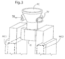
Figure 3 is a schematic perspective view of the upper region of a ceramic investment shell mold having a pour cup and dual mold cavity regions connected by gating. -
Figure 4 is a schematic elevation of a preheated mold placed on a mold-locating fixture or stand that is carried on an elevator between a lower mold-receiving chamber and an upper vacuum casting chamber ofFigure 1 . -
Figure 5 is a schematic perspective view of the induction coil support frames and the VIHT coil mounted on the support frames. -
Figure 6 is a schematic perspective view of the induction co il support frames and multiple VIHT coils mounted on the support frames to supply heat to multiple pour cups of a preheated mold. -
Figure 7 is a perspective view of a molten metal filter residing in the mold pour cup. - One illustrative embodiment of the invention relates to the vacuum casting of molten metallic material in a preheated mold in a vacuum casting chamber under conditions that reduce or eliminate shrinkage defects in the cast part and unwanted oxide surface scale on the cast parts. Moreover, the vacuum casting method is conducted under conditions that avoid contamination of solidified metallic material remaining in the mold pour cup (or other reservoir) after solidification so that it can be reused as revert in the casting another cast part.
-
Figures 1-5 show apparatus pursuant to an illustrative embodiment of the invention for vacuum melting and casting a metallic material pursuant to illustrative embodiments of the invention. Metallic materials which can be vacuum melted and cast include, but are not limited to, metals, metal alloys, intermetallic compounds, and other metallic materials. For purposes of illustration and not limitation of the invention, the method and apparatus will be described in connection with the vacuum melting and vacuum casting of a nickel base superalloy (or cobalt base superalloy) of the types used in the manufacture of gas turbine components, such as turbine blades, turbine vanes, turbine buckets and other components. Such nickel base superalloys and cobalt base superalloys are well known and include, but are not limited to, Mar-M 247 and Rene 80. The invention is especially useful in the vacuum casting of nickel base or cobalt base superalloys that contain oxygen-reactive alloying elements, such as hafnium (Hf), zirconium (Zr), titanium (Ti) aluminum, etc. that, when cast in air, form unwanted oxide scales (e. g. hafnium oxide) on last-to-solidify or other regions of the cast part. - The illustrative apparatus comprises upper
vacuum casting chamber 10 and a lower mold-receivingchamber 12 communicated to one another by a movable (e.g. slidable)valve 14 residing on intermediate chamber wall W for opening and closing the opening OP through which mold M moves betweenchambers chamber 12 to thevacuum casting chamber 10 for casting, thevalve 14 is opened, and the preheated mold M is raised byelevator 50 upwardly into thevacuum casting chamber 10. The uppervacuum casting chamber 10 is maintained under a vacuum (subambient pressure), such as less than about 0.020 mm Hg and preferably less than 0.001 mm Hg when a nickel base or cobalt base superalloy is being melted and cast in the preheated mold in thechamber 10. The lower mold-receivingchamber 12 typically is maintained at the same vacuum level aschamber 10 once the preheated mold is received in thechamber 12. - Typically, the mold M is preheated in a separate external mold preheat furnace (not shown) that can be gas-fired, electrical or other type. The preheated mold M then is moved from the preheating furnace into the mold- receiving
chamber 12. The mold M is manually or robotically moved intochamber 12 through a gas-tightsealable door 32 that opens to ambient air atmosphere. The preheated mold M can be positioned inchamber 12 onto a mold-locating fixture or stand 72 residing on a lift orelevator 50,Figure 4 . Theelevator 50 is raised or lowered via aram 51 andram actuator 53, such as a hydraulic, electrical or other motor, located outside or insidechamber 12. After thedoor 32 is closed and gas-tight sealed, a relative vacuum typically is established in thechamber 12 by one or more suitable vacuum pump(s) 61. - The lower mold-
receiving chamber 12 optionally may include conventional electrical resistance heating coil(s) or other heating device to preheat or supplement preheating the mold thereto by a valved opening OP2 similar to opening OP between thechambers valve 14. After the solid charge to be melted is placed in thechamber 16 and thedoor 17 closed, thechamber 16 can be evacuated by one or more suitable vacuum pumps 65 so that the solid charge to be melted can be lowered fromchamber 16 into thecrucible 30 in evacuatedchamber 10 by a hoist or other transfer device residing inchamber 16. - The
crucible 30 is mounted onmovable door 32 that opens to the ambient air atmosphere to permit a preheated mold M to be placed on theelevator 50 in thechamber 12. Thedoor 32 is movable to a closed, gas-tight sealed position forming a wall or wall portion of thechambers chambers chamber 10 andchamber 12. - When the
door 32 is closed and vacuum-tight sealed, thecrucible 30 is positioned above a vacuum induction hot topping induction coil (VIHT coil) 40 mounted on one ormore support plates 41 that, in turn, are supported on a firstcross support frame 42. Thecross frame 42, in turn, is adjustably mounted on the top rails of thesecond support frame 44, which includes adjustment holes 45 so that the position of theVIHT coil 40 can be initially adjusted relative to the position of the melt stream poured from thecrucible 30 into the mold M. Thesecond frame 44 is mounted on the intermediate wall W disposed between themold preheating chamber 12 and thevacuum casting chamber 10. - The
VIHT coil 40 comprises a water-cooled copper tubing coil faced on its inner surface with a ceramic grout material such as a zircon, alumina, silica, or a mixture thereof to protect the tubing coil from the heat of the melt stream discharged from thecrucible 30. To this end, thecoil 40 includes suitable fittings F to connect to cooling water conduits represented by arrows inFigure 5 . - Electrical power is supplied to the
coil 40 by electrical power wires shown schematically as lines L, inFigure 2 , from an external power source S, such as an Inductotherm Vacuum Induction power source, mounted on the exterior of the adjacent wall of thevacuum casting chamber 10 or other suitable location. - In
Figures 1-4 , the mold M is illustrated as a ceramic investment shell mold having a pour cup PC (melt reservoir) communicated by gating G to dual mold cavities MC1, MC2 residing within respective mold cavity-forming mold regions R1, R2 of the mold. The mold cavities MC1, MC2 (shown schematically) can have the shape of a gas turbine engine blade to be cast, although the mold cavities can have any other shape corresponding to the cast part to be made. The ceramic investment shell mold is formed as one-piece by the well known lost wax investment molding process. The invention, however, envisions using other types of molds such as including, but not limited to, machined refractory metal or ceramic molds, or preformed ceramic molds. - Moreover, although the illustrative embodiments of
Figures 1-4 show the mold M as having an integral upper pour cup PC to function as the melt reservoir, the invention envisions use of other types of molds having an internal melt reservoir or of molds having a melt reservoir separate from the mold yet communicated to the mold cavities to provide excess melt therein for feeding to the mold cavities during solidification to eliminate shrinkage defects in the cast part. - In
Figures 3-4 , the mold pour cup PC of the preheated mold M is illustrated as being initially positioned on locatingtubes 71 of the mold-locating fixture or stand 72 that is fixedly mounted on theelevator 50 in thechamber 12. Theelevator 50 then is raised to position the preheated mold to the casting position shown inFigures 1 and2 invacuum chamber 10. - A
molten metal filter 60 may be placed in the pour cup PC, as shown inFigure 7 to remove dross and other contaminants from the melt stream before its enters the mold cavites MC1, MC2 . InFigure 7 , thefilter 60 includes lockingtabs 61 that enter and engage in respective slots SL in the pour cup PC to lock the filter in position. The filter alternately, or in addition, can be placed in the gating G of the mold. An advantage of the invention is that the electromagnetic field ofcoil 40 is not affected by the presence of thefilter 60 and feeding of the solidification shrinkage continues as if the filter were not in the pour cup. This is in contrast to prior process using exothermic hot topping applied after casting where any filter must be removed prior to application of the exothermic material. - In practice of an illustrative method embodiment of the invention, the mold M is preheated in the separate mold preheating furnace while the mold is held in a pour cup-down position. After the mold M is preheated in the external preheating furnace to the desired elevated (superambient) casting temperature, the preheated mold is inverted and placed on the locating
tubes 71 of mold-locating fixture or stand 72 that resides on theelevator 50 in thechamber 12. Thedoor 32 is closed and sealed gastight. - The
chamber 12 then typically is evacuated to the same vacuum level aschamber 10, and then thevalve 14 is opened and the preheated mold M on fixture or stand 72 is raised using theelevator 50 to the casting position where the pour cup PC is positioned within and locally adjacent to theVIHT coil 40 and beneath thecrucible 30 where the pour cup PC can receive the poured melt stream from thecrucible 30. - The solid charge in the
crucible 30 can be melted under vacuum inchamber 10 before or after the preheated mold M is raised to the casting position. Typically, the mold M is preheated outside thechambers elevator 50 inchamber 12 concurrent with the melting of the solid charge in thecrucible 30 under vacuum inchamber 10. - The
crucible 30 then is rotated to introduce (pour) the superalloy melt into the pour cup PC (melt reservoir) and gating G of preheated mold M residing in avacuum chamber 10 so as to fill a mold cavities MC1, MC2 with the superalloy melt via the pour cup PC and gating G. The superalloy melt is introduced into the superalloy melt and to leave excess superalloy melt in the pour cup PC as a melt reservoir and in the gating G above the mold cavities. - Immediately after the mold is filled, the
VIHT coil 40 is energized by power source S to locally heat the superalloy melt remaining in the pour cup PC and adjacent gating G if needed to maintain it molten as the superalloy melt solidifies under vacuum in the mold cavities MC1, MC2 of the preheated mold M inchamber 10. The electromagnetic field of thecoil 40 couples to the excess superalloy melt remaining in the pour cup to locally heat the excess melt in the pour cup and adjacent gating without substantially heating the regions R1, R2 of the mold in which the mold cavities reside. Thecoil 40 typically is energized until the superalloy melt solidifies completely in the mold cavities MC1, MC2 and then the power is reduced to allow the alloy in the resevoir (pour cup) to solidify prior to removing from the vacuum furnace. - The inner diameter and height (number of coil turns) of the
coil 40 and as well as the spacing of theVIHT coil 40 relative to the mold pour cup PC and the level of coil energization is/are selected in dependence on the dimensions of the mold pour cup PC and amount of excess superalloy melt therein so that the coil's electromagnetic field couples with the excess superalloy melt in the pour cup to locally heat it as the superalloy melt solidifies in the mold cavities. - The
induction coil 40 is designed to maximize coupling with the excess superalloy in the pour cup PC by minimizing the distance from the molten alloy to the coil. Typically the distance ranges from 2-4 inches but may be more or less depending on specific component geometries. Further a minimum of energy is used to maintain the alloy in the pour cup PC in a molten state. This energy may be varied during operation in order to allow the alloy in the pour cup to freeze over providing for a minimum of oxides and nitrides in the residual alloy in the pour cup. This ensures it will be suitable for re-use. It is also advantageous to time the freezing of the alloy in the pour cup to the end of solidification in the casting so that the mold is removed from the castingchamber 10 andlower chamber 12 in time to allow another mold to be loaded in time to pour without adversely affecting cycle time. - The superalloy melt solidifies under vacuum in the mold cavities MC1, MC2 over time to produce an equaixed grain, superalloy cast part without shrinkage defects and without the presence of a reactive element oxide scale resulting from oxidation of a reactive element of the superalloy, such as hafnium present in certain nickel base superalloys. If desired, the rate of solidification in
chamber 10 can be increased by introducing an inert thermally conductive cooling gas, such as argon, into thechamber 10 for a period of time after the superalloy melt is poured into the preheated mold M. - Once the superalloy melt is completely solidified in the mold and cooled to a few hundred degrees below the alloy solidus temperature, the
valve 14 can be opened, and the cast mold lowered intochamber 12 using themold elevator 50 where it can be cooled to ambient temperature inside thechamber 12, or it can be removed outside of thechamber 12 to finish cooling in ambient air. - As illustrated in
Figure 6 , multiple VIHT coils 40, 40', 40" can be provided on support plate 41' of supports 42', 44' in the event the mold M includes multiple pour cups or other reservoirs, such as might be used to cast a larger gas turbine engine vane. Design and operation of thecoils single VIHT coil 40. - Practice of the present invention is advantageous to avoid occurrence of severe reactions (flash and burning) associated with previously-used exothermic material placed on the melt in the mold pour cup, to avoid contamination of solidified metallic material remaining in the mold pour cup after solidification so that it can be reused, to avoid shrinkage defects in the cast part, and to avoid the formation of unwanted reactive element oxides as surface scale at last-to-solidify regions of the cast part when certain superalloys are cast.
- The following example is offered to further illustrate and not limit the invention.
- An equiaxed grain gas turbine engine blade having a length of 26 inches and weight of 23 pounds was vacuum cast from a Mar-M 2 47 nickel base superalloy using apparatus similar to that described above and shown in
Figures 1-5 . - The mold preheat temperature was 2200°F. The superalloy pour temperature was 2705°F using a melting cycle time in the crucible of about 25 minutes. The superalloy melt pour time into the mold was about 10 seconds.
- The VIHT coil was 8 inches in inner diameter with 4 coil turns. The inner surface of the VIHT oil was faced with a alumina, silica, zircon grout ceramic layer applied by hand and formed by mandrel. The inner surface of the VIHT coil was spaced 0.5 inch from the largest diameter of the pour cup. The VIHT coil was energized immediately after pouring the molten alloy into the mold and at a power level of 90 kW for 10 minutes. Then power was gradually reduced to 0 kW until alloy in the pour cup froze. The total VIHT cycle time is about 20 minutes. After the alloy in the pour cup was solidified the mold was lowered into the
lower mold chamber 12 and removed to finish cooling in air. The vacuum level in the vacuum casting chamber at pour was 15 µm-Hg. - The cast blade had an equiaxed grain microstructure and was free of shrinkage defects and hafnium oxide scale at the last-to-solidify root region of the cast blade. Moreover, the solidified superalloy in the pour cup was closed and free of oxide contamination so that it could be reused as revert to cast another part.
- Another illustrative embodiment of the invention is useful, although not limited to, casting of stainless steel (or other metals or alloys) in air. Such stainless steels include, but are not limited to, ferritic, austenitic and PH (precipitation hardening) stainless steels. The method and apparatus involve introducing molten metallic material (melt) into a preheated mold in ambient air (atmospheric air) wherein the mold has a melt reservoir, such as a pour cup, and gating that feed the melt to one or more mold cavities. Excess melt is provided in the melt reservoir, such as the pour cup, and the gating for feeding to the one or more mold cavities during solidification there. An induction coil like
coil 40 is disposed locally adjacent to the melt reservoir and is energized in a manner to locally heat the excess melt in the melt reservoir to maintain it molten as the molten metallic material solidifies in air in the one or more mold cavities of the preheated mold. The excess molten metallic material is fed as needed to eliminate shrinkage defects as solidification proceeds in air in the mold cavity. - For example, the
chambers chambers Figure 5 and cast in air using a crucible of the type shown as "30" inFigures 1 and2 containing the stainless steel melt located above the mold pour cup in air. The VIHT coil could be supported on a support plate and supports like those shown inFigure 5 . - Although the invention has been described hereinabove in terms of specific embodiments thereof, it is not intended to be limited thereto but rather only to the extent set forth hereafter in the appended claims.
- In more detail, the following aspects and combination of features are part of the present disclosure:
- According to one aspect of the present disclosure, a method of casting a molten metallic material is provided, said method comprising:
- introducing molten metallic material into a preheated mold via a melt reservoir and gating that feeds the molten metallic material to one or more mold cavities so as to fill the one or more mold cavities with the molten metallic material, leaving excess molten metallic material in the melt reservoir and gating, and energizing an induction coil disposed locally adjacent to the melt reservoir in a manner to locally heat the molten metallic material in the reservoir to maintain it molten as the molten metallic material solidifies in the mold cavity of the preheated mold.
- According to some embodiments of this aspect, the induction coil is energized to locally heat the molten metallic material in the reservoir and the gating adjacent to the reservoir without substantially heating the region of the mold in which the one or more mold cavities reside.
- According to some embodiments of this aspect, the melt reservoir is a mold pour cup disposed above the mold cavity.
- According to some embodiments of this aspect, the induction coil is energized until the molten metallic material in the mold cavity solidifies.
- According to some embodiments of this aspect, the mold is disposed in a vacuum chamber that is evacuated to a pressure less than 20 pm Hg before the molten metallic material is introduced into the preheated mold residing in the vacuum chamber.
- According to some embodiments of this aspect, the mold is disposed in air.
- The method of this aspect may also include relatively moving the preheated mold and the induction coil so that the induction coil resides locally around the melt reservoir prior to introduction of the molten metallic material into the preheated mold.
- The method of this aspect may also include the additional step of reusing the solidified material remaining in the melt reservoir in making another casting.
- The method of this aspect may also include providing multiple reservoirs and a respective induction coil adjacent each reservoir.
- According to another aspect of the present disclosure, a method of vacuum casting a molten superalloy containing an oxygen-reactive alloyant is provided, said method comprising introducing molten superalloy melt into a preheated mold in a vacuum chamber via a melt reservoir and gating that feed the melt to one or more mold cavities so as to fill the one or more mold cavities with the superalloy melt, leaving excess superalloy melt in the melt reservoir and gating, and energizing an induction coil disposed adjacent to the pour cup in a manner to locally heat the superalloy melt in the pour cup to maintain it molten as the superalloy melt solidifies under vacuum in the mold cavity of the preheated mold.
- According to some embodiments of this aspect, the superalloy contains oxygen-reactive hafnium, zirconium, titanium, and/or aluminum.
- The method of this aspect may also include solidifying the superalloy melt in the mold to form an equiaxed grain cast part without shrinkage defects.
- The method of this aspect may also include solidifying the superalloy melt without the presence of an oxide scale.
- According to some embodiments of this aspect, the induction coil is energized to locally heat the pour cup and gating adjacent to the pour cup without substantially heating the region of the mold in which the one or more mold cavities reside.
- According to some embodiments of this aspect, the induction coil is energized until the molten superalloy in the mold cavity solidifies.
- According to some embodiments of this aspect, the vacuum chamber is evacuated to a pressure less than 20 µm Hg before the molten superalloy is introduced into the preheated mold residing in the vacuum chamber.
- The method of this aspect may also include relatively moving the preheated mold and the induction coil in the vacuum chamber so that the induction coil resides locally around the pour cup prior to introduction of the molten superalloy into the preheated mold.
- According to some embodiments of this aspect,the mold cavity has the shape of a gas turbine blade or vane to produce a cast blade or cast vane.
- The method of this aspect may also include providing multiple reservoirs and a respective induction coil adjacent each reservoir.
- According to yet another aspect of the present disclosure, an apparatus for casting of a molten metallic material is provided, said apparatus comprising a crucible containing a melt to be cast into a preheated mold and an induction coil disposed locally adjacent to a melt reservoir communicating to a mold cavity of the preheated mold, the induction coil being energizable in a manner to locally heat excess molten metallic material provided in the melt reservoir so as to maintain it molten as the molten metallic material solidifies in the mold cavity.
- According to some embodiments of this aspect, the induction coil and the preheated mold are relatively movable to position the induction coil locally around the melt reservoir.
- According to some embodiments of this aspect, the induction coil is disposed around the periphery of the melt reservoir.
- The apparatus of this aspect may also include multiple induction coils locally adjacent to a respective melt reservoir.
Claims (15)
- Method of casting a molten metallic material, comprising the following steps:i) introducing molten metallic material into a preheated mold (M) from a melt reservoir via a gating (G), such that the molten metallic material is fed to one or more mold cavities (MC1, MC2) so as to fill the one or more mold cavities (MC1, MC2) with the molten metallic material, wherein excess molten metallic material is left in the melt reservoir and in the gating (G), andii) energizing an induction coil (40), disposed locally adjacent to the melt reservoir in a manner to locally heat the molten metallic material in the reservoir to maintain it molten as the molten metallic material solidifies in the mold cavity (MC1, MC2) of the preheated mold (M).
- The method of claim 1,
wherein the method is conducted in a vacuum chamber (10) and the steps i) and ii) are conducted in vacuum; or
wherein the mold (M) is disposed in air and the method with steps i) and ii) is conducted in air. - The method of claim 1 or 2,
wherein the induction coil (40) is energized to locally heat the molten metallic material in the reservoir and the gating (G) adjacent to the reservoir without substantially heating the region (R1, R2) of the mold in which the one or more mold cavities (MC1, MC2) reside. - The method of one of the claims 1 to 3,
wherein the induction coil (40) is energized until the molten metallic material in the mold cavity (MC1, MC2) solidifies. - The method of one of the claims 2 to 4,
wherein the vacuum chamber (10) is evacuated to a pressure less than 20 µm Hg before the molten metallic material is introduced into the preheated mold (M), residing in the vacuum chamber (10). - The method of one of the claims 1 to 5,
including relatively moving the preheated mold (M) and the induction coil (40) so that the induction coil (40) resides locally around the melt reservoir prior to introduction of the molten metallic material into the preheated mold (M). - The method of one of the claims 1 to 6,
including the additional step of reusing the solidified material remaining in the melt reservoir in making another casting. - The method of one of the claims 1 to 7,
including providing multiple reservoirs and a respective induction coils (40, 40', 40") adjacent to each reservoir. - The method of one of the claims 1 to 8,
wherein the mold cavity (MC1, MC2) has the shape of a gas turbine blade or vane to produce a cast blade or cast vane. - The method of one of the claims 1 to 9,
wherein molten superalloy, containing an oxygen-reactive alloyant, is used as the molten metallic material and wherein the superalloy preferably contains oxygen-reactive hafnium, zirconium, titanium, and/or aluminum. - The method of claim 10,
wherein the method includes solidifying the superalloy melt in the mold to form an equiaxed grain cast part without shrinkage defects. - The method of claim 10,
wherein the method includes solidifying the superalloy melt without the presence of an oxide scale. - The method of one of the claims 1 to 12,
wherein the melt reservoir is a mold pour cup (PC) disposed above the mold cavity, and preferably disposed integrally above the mold cavity. - An apparatus for casting of a molten metallic material,
comprising:- a crucible (30), containing a melt to be cast into a preheated mold (M); and- an induction coil (40), disposed locally adjacent to a melt reservoir communicating to a mold cavity (MC1, MC2) of the preheated mold (M),wherein the induction coil (40) is energizable in a manner to locally heat excess molten metallic material provided in the melt reservoir so as to maintain the molten metallic material molten as the molten metallic material solidifies in the mold cavity (MC1, MC2). - The apparatus of claim 14,
wherein the induction coil (40) and the preheated mold (M) are relatively movable to position the induction coil (40) locally around the melt reservoir and wherein the induction coil (40) is preferably disposed around the periphery of the melt reservoir and where more preferably the apparatus includes multiple induction coils (40, 40', 40") locally adjacent to a respective melt reservoir.
Applications Claiming Priority (1)
| Application Number | Priority Date | Filing Date | Title |
|---|---|---|---|
| US13/815,503 US9381569B2 (en) | 2013-03-07 | 2013-03-07 | Vacuum or air casting using induction hot topping |
Publications (1)
| Publication Number | Publication Date |
|---|---|
| EP2774701A1 true EP2774701A1 (en) | 2014-09-10 |
Family
ID=50156563
Family Applications (1)
| Application Number | Title | Priority Date | Filing Date |
|---|---|---|---|
| EP14155447.7A Withdrawn EP2774701A1 (en) | 2013-03-07 | 2014-02-17 | Vacuum or air casting using induction hot topping |
Country Status (3)
| Country | Link |
|---|---|
| US (1) | US9381569B2 (en) |
| EP (1) | EP2774701A1 (en) |
| JP (1) | JP6391937B2 (en) |
Cited By (2)
| Publication number | Priority date | Publication date | Assignee | Title |
|---|---|---|---|---|
| CN106734932A (en) * | 2016-12-30 | 2017-05-31 | 大连船用推进器有限公司 | Large-scale marine propeller casts rising head induction heating apparatus |
| CN110142394A (en) * | 2019-05-29 | 2019-08-20 | 赵树军 | A kind of new-type frame suction pouring process units |
Families Citing this family (10)
| Publication number | Priority date | Publication date | Assignee | Title |
|---|---|---|---|---|
| FR3016817B1 (en) * | 2014-01-24 | 2016-02-12 | Snecma | METHOD FOR PREHEATING A SET OF CARAPACED MOLDS FOR LOST WAX FOUNDRY |
| WO2016069064A1 (en) * | 2014-10-30 | 2016-05-06 | Retech Systems Llc | Dual vacuum induction melting & casting |
| US11123791B2 (en) | 2017-10-16 | 2021-09-21 | General Electric Company | Method for casting a mold |
| US11123790B2 (en) | 2017-10-16 | 2021-09-21 | General Electric Company | Apparatus for casting a mold |
| CN107803493A (en) * | 2017-12-12 | 2018-03-16 | 安徽应流集团霍山铸造有限公司 | A kind of Turbine Casting pours into a mould special purpose device |
| GB201900422D0 (en) * | 2019-01-11 | 2019-02-27 | Hatton Designs Of London Ltd | Ceramic pour cup |
| WO2021015074A1 (en) * | 2019-07-23 | 2021-01-28 | 三菱電機株式会社 | Casting mold, and method for manufacturing casting mold |
| US20220055096A1 (en) * | 2020-08-21 | 2022-02-24 | Porvair, Plc | Pour Cup with Filter Lock |
| KR102599520B1 (en) * | 2021-01-06 | 2023-11-07 | 진성정밀금속(주) | A vacuum investment casting system and method of turbine wheel for a turbocharger |
| CN114101604B (en) * | 2021-12-08 | 2023-08-18 | 贵州航天新力科技有限公司 | One-furnace multi-casting device of small vacuum induction furnace and use method thereof |
Citations (10)
| Publication number | Priority date | Publication date | Assignee | Title |
|---|---|---|---|---|
| GB1181278A (en) * | 1967-06-29 | 1970-02-11 | Trw Inc | Improvements in or relating to Articles with Controlled Grain Structure and Methods of Making Same |
| US3841384A (en) | 1973-02-21 | 1974-10-15 | Howmet Corp | Method and apparatus for melting and casing metal |
| US4738713A (en) * | 1986-12-04 | 1988-04-19 | The Duriron Company, Inc. | Method for induction melting reactive metals and alloys |
| US4813470A (en) * | 1987-11-05 | 1989-03-21 | Allied-Signal Inc. | Casting turbine components with integral airfoils |
| US4832112A (en) | 1985-10-03 | 1989-05-23 | Howmet Corporation | Method of forming a fine-grained equiaxed casting |
| US5592984A (en) | 1995-02-23 | 1997-01-14 | Howmet Corporation | Investment casting with improved filling |
| JPH10277702A (en) * | 1997-04-02 | 1998-10-20 | Fuji Electric Co Ltd | Heat insulating device for runner of mold |
| WO1999058270A1 (en) * | 1998-05-14 | 1999-11-18 | Howmet Research Corporation | Investment casting using pour cup reservoir with inverted melt feed gate |
| US6446698B1 (en) | 2001-03-12 | 2002-09-10 | Howmet Research Corporation | Investment casting with exothermic material |
| US6640877B2 (en) | 1998-05-14 | 2003-11-04 | Howmet Research Corporation | Investment casting with improved melt filling |
Family Cites Families (24)
| Publication number | Priority date | Publication date | Assignee | Title |
|---|---|---|---|---|
| US3008855A (en) * | 1959-01-26 | 1961-11-14 | Gen Motors Corp | Turbine blade and method of making same |
| US3310850A (en) | 1963-12-13 | 1967-03-28 | Rheinstahl Huettenwerke Ag | Method and apparatus for degassing and casting metals in a vacuum |
| US3420291A (en) | 1965-12-29 | 1969-01-07 | Trw Inc | Method for reducing metal casting porosity |
| US3888300A (en) | 1970-06-15 | 1975-06-10 | Combustible Nucleaire Sa Soc I | Apparatus for the continuous casting of metals and the like under vacuum |
| US3788382A (en) | 1970-11-25 | 1974-01-29 | J Richey | Vacuum metal casting apparatus |
| US3897815A (en) * | 1973-11-01 | 1975-08-05 | Gen Electric | Apparatus and method for directional solidification |
| JPS5233143A (en) * | 1975-09-09 | 1977-03-14 | Nippon Steel Corp | Compressive molten bath method by industive heat way |
| JPS6127166A (en) | 1984-07-13 | 1986-02-06 | Kubota Ltd | Die casting method |
| GB8604386D0 (en) | 1986-02-21 | 1986-03-26 | Cosworth Res & Dev Ltd | Casting |
| US4667728A (en) * | 1986-04-21 | 1987-05-26 | Pcc Airfoils, Inc. | Method and apparatus for casting articles |
| US5335711A (en) | 1987-05-30 | 1994-08-09 | Ae Plc | Process and apparatus for metal casting |
| WO1994020240A1 (en) | 1993-03-12 | 1994-09-15 | Hitachi Metals, Ltd. | Vacuum suction casting apparatus and method using the same |
| US5860468A (en) | 1993-07-28 | 1999-01-19 | Cook; Arnold J. | Vacuum die casting |
| JP3080582B2 (en) * | 1996-05-27 | 2000-08-28 | ダイハツ金属工業株式会社 | Metal casting method |
| US5842511A (en) | 1996-08-19 | 1998-12-01 | Alliedsignal Inc. | Casting wheel having equiaxed fine grain quench surface |
| CN1072071C (en) | 1997-04-03 | 2001-10-03 | 安井章瑞 | Method and casting device for precision casting |
| US5931214A (en) | 1997-08-07 | 1999-08-03 | Howmet Research Corporation | Mold heating vacuum casting furnace |
| JP3963290B2 (en) | 1998-02-27 | 2007-08-22 | ヤマハマリン株式会社 | Outboard motor |
| US7418993B2 (en) | 1998-11-20 | 2008-09-02 | Rolls-Royce Corporation | Method and apparatus for production of a cast component |
| EP1240960B1 (en) * | 2001-03-15 | 2007-07-25 | Nissin Kogyo Co., Ltd | Method of deoxidation casting and deoxidation casting machine |
| JP2002331352A (en) * | 2001-05-09 | 2002-11-19 | Mitsubishi Materials Corp | Manufacturing method for turbine blade |
| US7448428B2 (en) * | 2005-10-14 | 2008-11-11 | Pcc Airfoils, Inc. | Method of casting |
| US8459331B2 (en) * | 2011-08-08 | 2013-06-11 | Crucible Intellectual Property, Llc | Vacuum mold |
| US9475119B2 (en) * | 2012-08-03 | 2016-10-25 | General Electric Company | Molded articles |
-
2013
- 2013-03-07 US US13/815,503 patent/US9381569B2/en not_active Expired - Fee Related
-
2014
- 2014-01-29 JP JP2014013909A patent/JP6391937B2/en not_active Expired - Fee Related
- 2014-02-17 EP EP14155447.7A patent/EP2774701A1/en not_active Withdrawn
Patent Citations (12)
| Publication number | Priority date | Publication date | Assignee | Title |
|---|---|---|---|---|
| GB1181278A (en) * | 1967-06-29 | 1970-02-11 | Trw Inc | Improvements in or relating to Articles with Controlled Grain Structure and Methods of Making Same |
| US3841384A (en) | 1973-02-21 | 1974-10-15 | Howmet Corp | Method and apparatus for melting and casing metal |
| US4832112A (en) | 1985-10-03 | 1989-05-23 | Howmet Corporation | Method of forming a fine-grained equiaxed casting |
| US4738713A (en) * | 1986-12-04 | 1988-04-19 | The Duriron Company, Inc. | Method for induction melting reactive metals and alloys |
| US4738713B1 (en) * | 1986-12-04 | 1994-01-04 | Duriron Company, Inc. | |
| US4813470A (en) * | 1987-11-05 | 1989-03-21 | Allied-Signal Inc. | Casting turbine components with integral airfoils |
| US5592984A (en) | 1995-02-23 | 1997-01-14 | Howmet Corporation | Investment casting with improved filling |
| JPH10277702A (en) * | 1997-04-02 | 1998-10-20 | Fuji Electric Co Ltd | Heat insulating device for runner of mold |
| WO1999058270A1 (en) * | 1998-05-14 | 1999-11-18 | Howmet Research Corporation | Investment casting using pour cup reservoir with inverted melt feed gate |
| US6019158A (en) | 1998-05-14 | 2000-02-01 | Howmet Research Corporation | Investment casting using pour cup reservoir with inverted melt feed gate |
| US6640877B2 (en) | 1998-05-14 | 2003-11-04 | Howmet Research Corporation | Investment casting with improved melt filling |
| US6446698B1 (en) | 2001-03-12 | 2002-09-10 | Howmet Research Corporation | Investment casting with exothermic material |
Cited By (2)
| Publication number | Priority date | Publication date | Assignee | Title |
|---|---|---|---|---|
| CN106734932A (en) * | 2016-12-30 | 2017-05-31 | 大连船用推进器有限公司 | Large-scale marine propeller casts rising head induction heating apparatus |
| CN110142394A (en) * | 2019-05-29 | 2019-08-20 | 赵树军 | A kind of new-type frame suction pouring process units |
Also Published As
| Publication number | Publication date |
|---|---|
| US20140251572A1 (en) | 2014-09-11 |
| JP6391937B2 (en) | 2018-09-19 |
| US9381569B2 (en) | 2016-07-05 |
| JP2014205192A (en) | 2014-10-30 |
Similar Documents
| Publication | Publication Date | Title |
|---|---|---|
| US9381569B2 (en) | Vacuum or air casting using induction hot topping | |
| CA2100832C (en) | Method and apparatus for making intermetallic castings | |
| US5335711A (en) | Process and apparatus for metal casting | |
| JP2007167954A (en) | Method for casting molten metallic material and casting apparatus | |
| EP1797978A2 (en) | Die casting in investment mold | |
| US20070199676A1 (en) | Composite mold with fugitive metal backup | |
| EP0728546B1 (en) | Directionally solidified investment casting with improved filling | |
| EP1110645A2 (en) | Liquid metal bath furnace and casting method | |
| EP2450125A2 (en) | Die casting system machine configurations | |
| CN110421144B (en) | Pressure-regulating precision casting method for high-temperature alloy floating wall tile under action of external electromagnetic field | |
| US3635791A (en) | Pressure pouring in a vacuum environment | |
| EP1778426B1 (en) | A method for producing a functionally gradient component | |
| EP2551038B1 (en) | Die casting system and method | |
| EP2450131B1 (en) | Melting unit for a die casting system | |
| Yang et al. | A Combined Electromagnetic Levitation Melting, Counter‐Gravity Casting, and Mold Preheating Furnace for Producing TiAl Alloy | |
| EP0293960B1 (en) | Process and apparatus for metal casting | |
| EP1085955B1 (en) | Investment casting using pour cup reservoir with inverted melt feed gate | |
| US8312913B2 (en) | Casting process | |
| CN111136258B (en) | Heat treatment method of high-temperature Ti-based alloy casting | |
| EP1101551B1 (en) | Investment casting using melt reservoir loop | |
| CN114273638A (en) | Low-pressure precision casting method of magnesium alloy thin-wall shell part | |
| WO1999058272A1 (en) | Investment casting using sealable pressure cap | |
| RU2573283C1 (en) | Method of producing of metallurgical blanks, shaped castings, and device for its implementation | |
| Woycik et al. | Low-Pressure Metal Casting |
Legal Events
| Date | Code | Title | Description |
|---|---|---|---|
| PUAI | Public reference made under article 153(3) epc to a published international application that has entered the european phase |
Free format text: ORIGINAL CODE: 0009012 |
|
| 17P | Request for examination filed |
Effective date: 20140217 |
|
| AK | Designated contracting states |
Kind code of ref document: A1 Designated state(s): AL AT BE BG CH CY CZ DE DK EE ES FI FR GB GR HR HU IE IS IT LI LT LU LV MC MK MT NL NO PL PT RO RS SE SI SK SM TR |
|
| AX | Request for extension of the european patent |
Extension state: BA ME |
|
| REG | Reference to a national code |
Ref country code: HK Ref legal event code: DE Ref document number: 1196332 Country of ref document: HK |
|
| 17Q | First examination report despatched |
Effective date: 20151214 |
|
| REG | Reference to a national code |
Ref country code: HK Ref legal event code: WD Ref document number: 1196332 Country of ref document: HK |
|
| STAA | Information on the status of an ep patent application or granted ep patent |
Free format text: STATUS: THE APPLICATION IS DEEMED TO BE WITHDRAWN |
|
| 18D | Application deemed to be withdrawn |
Effective date: 20200901 |