EP2774530A1 - Procédé de tomographie photoacoustique - Google Patents
Procédé de tomographie photoacoustique Download PDFInfo
- Publication number
- EP2774530A1 EP2774530A1 EP13157616.7A EP13157616A EP2774530A1 EP 2774530 A1 EP2774530 A1 EP 2774530A1 EP 13157616 A EP13157616 A EP 13157616A EP 2774530 A1 EP2774530 A1 EP 2774530A1
- Authority
- EP
- European Patent Office
- Prior art keywords
- pulse
- sample
- excitation
- observation laser
- time interval
- Prior art date
- Legal status (The legal status is an assumption and is not a legal conclusion. Google has not performed a legal analysis and makes no representation as to the accuracy of the status listed.)
- Granted
Links
Images
Classifications
-
- G—PHYSICS
- G01—MEASURING; TESTING
- G01B—MEASURING LENGTH, THICKNESS OR SIMILAR LINEAR DIMENSIONS; MEASURING ANGLES; MEASURING AREAS; MEASURING IRREGULARITIES OF SURFACES OR CONTOURS
- G01B9/00—Measuring instruments characterised by the use of optical techniques
- G01B9/02—Interferometers
- G01B9/02094—Speckle interferometers, i.e. for detecting changes in speckle pattern
- G01B9/02095—Speckle interferometers, i.e. for detecting changes in speckle pattern detecting deformation from original shape
-
- A—HUMAN NECESSITIES
- A61—MEDICAL OR VETERINARY SCIENCE; HYGIENE
- A61B—DIAGNOSIS; SURGERY; IDENTIFICATION
- A61B5/00—Measuring for diagnostic purposes; Identification of persons
- A61B5/0059—Measuring for diagnostic purposes; Identification of persons using light, e.g. diagnosis by transillumination, diascopy, fluorescence
- A61B5/0073—Measuring for diagnostic purposes; Identification of persons using light, e.g. diagnosis by transillumination, diascopy, fluorescence by tomography, i.e. reconstruction of 3D images from 2D projections
-
- A—HUMAN NECESSITIES
- A61—MEDICAL OR VETERINARY SCIENCE; HYGIENE
- A61B—DIAGNOSIS; SURGERY; IDENTIFICATION
- A61B5/00—Measuring for diagnostic purposes; Identification of persons
- A61B5/0093—Detecting, measuring or recording by applying one single type of energy and measuring its conversion into another type of energy
- A61B5/0095—Detecting, measuring or recording by applying one single type of energy and measuring its conversion into another type of energy by applying light and detecting acoustic waves, i.e. photoacoustic measurements
Definitions
- the invention relates to a method for the photoacoustic tomography of sample volumes which have in their interior spectrally addressable absorption contrasts for electromagnetic radiation for at least one target structure.
- the invention also relates to a device for the photoacoustic localization of physiological structures in the interior of a biological tissue.
- excitation light from a predetermined partial spectrum of the electromagnetic spectrum is irradiated to a sample volume.
- the excitation light should enter the interior of the sample and possibly also be scattered, but only weakly or not at all absorbed by the majority of the sample material.
- predetermined target structures which are present in the sample interior in a priori unknown distribution, absorb the excitation light under heating and thus cause a localized thermal expansion of the absorber and in the boundary region of the surrounding sample material.
- the predetermined partial spectrum of the excitation radiation depends on the material properties of the sample and in particular also on those of the target structures which are to be localized photoacoustically. The user will have to choose a suitable sub-spectrum for his concrete sample in individual cases.
- a sample volume having intrinsically "spectrally-addressable" absorption contrasts for a target structure is, by definition, intended to be one for which one can find a partial spectrum of the electromagnetic spectrum from which light is absorbed by the target structure other than by the environment of the target structure.
- the PAT can also be used to localize target structures that absorb the light in a worse way than their surroundings and thereby measurably disturb the pressure wave propagation in the material, for example air pockets in the material or other material defects (defect screening).
- time-limited pressure waves are triggered inside the sample (photoacoustic effect).
- the pressure waves generated by absorption in the interior and then propagating to the sample surface lead to small and short-term deformations of the sample surface.
- the pulse energy of the excitation light has an appropriate value, which is also to be selected by the user for his specific sample itself. If the pulse energy is too low, the introduced energy dissipates during the pressure wave propagation so that virtually no deformations can be detected. Too high a pulse energy, however, can damage the sample irreversibly.
- pulse duration of an excitation light pulse in the order of a few nanoseconds preferably in the range of acoustic inclusion time of the absorber, and the irradiation in the range of a few mJ / cm 2 , one has with deformation amplitudes on the sample surface in the order of a few nanometers over a period of time of microseconds.
- the detection of the deformations of the sample surface and the subsequent evaluation of their spatial and temporal behavior allow the localization and possibly even the qualification and quantification of the target structures in the interior of the sample.
- the reconstruction of the source distribution of the optically excited pressure waves is a problem in itself solved.
- the PAT can be carried out as soon as deformations of the sample surface can be detected with sufficient accuracy and time resolution.
- Carp and Venugopalan describe measurement of pressure oscillations produced by a pulsed excitation laser beam.
- the measurement setup is based on a Mach-Zehnder interferometer, which uses a He-Ne laser as the observation light source.
- the observation laser light is dichroitically reflected in the beam path of the excitation laser and scattered mainly from the sample surface.
- the interferometer detects displacements of the sample surface from the phase shift of the observation laser light against a predetermined reference oscillation, which is introduced by a controllable acousto-optic modulator.
- pressure transducers can shade the sample against the excitation radiation and, on the other hand, require an acoustic impedance matching to the sample material.
- the observation laser light is applied selectively, in contrast to the excitation light applied over the entire area. It is thus possible to determine intermittent interference phases and thus surface shifts, whereby a complete time series of signals can be recorded at each measuring point.
- To determine the spatial distribution of the surface deformations of the sample it is necessary to move the measurement point irradiated with observation light relative to the sample, which here, for example, with a direction perpendicular to the direction of irradiation moving sample holder happens.
- Such shifts require approximately 0.5 s measurement pause, for which add 0.3 to 0.5 s measurement time per measurement point for 350 to 750 measurement points until a sample surface has been scanned by a few square centimeters.
- the authors indicate 7 to 15 minutes of acquisition time for all data required for tomographic reconstruction.
- a temporal sequence of deformation profiles with a sufficiently high support point density with respect to time and 2D location coordinates is a suitable initial data set for a tomographic reconstruction. It may be considered to resort to a measurement setup with a digital camera and to a holographic process from elastometry.
- Double pulse Electronic Speckle Interferometry DP-ESPI
- DP-ESPI double pulse Electronic Speckle Interferometry
- the DP-ESPI is a method of detecting surface transient vibrations involving two temporally successive illuminations of the surface with coherent light and recording at least one speckle pattern on a two-dimensional array of light detectors produced by the scattering of the light upon illumination (in the first instance electronic camera with light-sensitive pixels).
- DP-ESPI is from the work of Pedrini et al., Double-pulse electronic speckle interferometry, JOURNAL OF MODERN OPTICS, 1993, Vol. 40, No.1, 89-96 known.
- This work reports on the measurement of the deformations of a metal plate that is vibrated with a pendulum stop.
- the plate surface is illuminated with observation laser light and imaged onto a CCD camera.
- a small proportion (10%) of the observation light is reflected as a reference beam in front of the sample.
- a portion of the remaining observation light is scattered by the sample and passed as a sample beam through an aperture to the CCD camera.
- the purpose of the aperture is to increase the average size of the speckles present in the sample beam to approximately four times the width of the camera pixels.
- the incidence of the reference beam on the camera plane is at an angle to the sample beam in order to establish a phase ramp - and thus also a fringe pattern of the interference light intensity - along the pixel array (see FIG. 4 there).
- the period length of the fringe pattern is smaller than the average speckled diameter and at the same time has at least three (here: four) camera pixel spacings, then a phase profile representing the deformation of the sample between the two illumination pulses can be calculated directly from two closely spaced, successively recorded speckle patterns.
- a deformation profile results from this by means of "phase unwrapping" (see there Fig. 5, in particular Fig. 5e).
- An alternative solution is to use at least three instead of a photosensitive sensor.
- the light which contains the optical phase due to interference between the object beam and the reference beam, must be imaged according to the ESPI principle with at least three known phase positions between the two beams. If the light is distributed by means of a plurality of beam splitters to at least three sensors, which are geometrically finely adjustable or already designed according to the required phase positions, the three interference images can be recorded simultaneously.
- the method is equally applicable to time-critical operations and in principle equivalent to the approach described above using a phase ramp.
- a color camera that is to say a sensor with a spectrally dependent pixel arrangement.
- different color filters are arranged here in periodic repetition.
- To illuminate the sample at least three different wavelengths are used at the same time, for each of which then only a part of the camera pixels is sensitive.
- the modification of the optical path length can be realized, for example, via dichroic elements in the beam path.
- a structured phase mask in front of the sensor can be defined per pixel to modify the optical path length.
- the object of the invention is to propose a method for photoacoustic tomography, which allows a faster data acquisition for measuring the deformations of the sample surface than in the prior art.
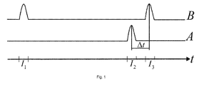
- a deformation profile is determined from two consecutively performed illuminations of a measuring surface on the sample with observation laser light and related to the time interval of a third light pulse, which is applied between the two observation laser pulses, to the later of the two observation laser pulses.
- This third light pulse is to enter the sample and be absorbed by the target structure. It represents the excitation light of the PAT measurement and comes from a different part of the electromagnetic spectrum than the observation laser light.
- the sequence of the three light pulses is repeated N times (where N is a predeterminable natural number) changing at least the said time interval to produce a sequence of N deformation profiles to N different time indices.
- the distance between two successive time indices assigned to the deformation profiles in the generated sequence is generally much smaller than the actual time span which lies between the metrological detection of two successive deformation profiles. Nevertheless, the sequence obtained by repeating the sequence of three light pulses approximates a "true sequence of deformation profiles" that occurs on the measuring surface within a few microseconds of the excitation pulse due to only a single excitation pulse. However, the capture of the "true sequence” would require the technicality of having an electronic camera capable of recording several million frames per second. The state of camera technology is currently three orders of magnitude lower.
- the sequence generated according to the invention represents a realizable measurement result and at the same time an adequate starting data set for a tomographic reconstruction in the sense of the PAT.
- An important advantage of the invention over the prior art is the fact that the metrological detection of all raw data for subsequent calculation of the sequence of deformation profiles readily in less than ten seconds, preferably in less than one second, more preferably in less than 200 milliseconds can be completed.
- the center distance between the second and the third time interval is the time interval ⁇ t at which a deformation profile is determined.
- the deformation profile is calculated as described in the prior art from the detected bacon patterns that are detected by the observation laser pulses of the first and the third time interval from an electronic camera.
- the deformation profile then represents the change in the deformation state of the sample surface between the first time interval (before arrival of the excitation pulse) and the third time interval ( ⁇ t after the arrival of the excitation pulse).
- the observation laser pulse which is irradiated onto the measurement surface in the first time interval, is referred to as a "leading" observation laser pulse.
- the excitation pulse follows in time, which in turn is followed by the "trailing" observation laser pulse in the third time interval.
- the excitation pulse may be a laser light pulse. It can also originate from another light source which is designed to emit light pulses at predetermined times, for example a flashlamp.
- the pulse duration of the excitation pulse should preferably be smaller than the acoustic transit time of the absorber (usually defined as the diameter of the absorber divided by the speed of sound in the absorber) and be on the order of nanoseconds in order to maximize the pressure amplitude.
- the pulse duration is preferably less than 100 ns, particularly preferably less than 10 ns.
- the second time interval in which the sample is illuminated with excitation light should be variable between the first and third time interval with respect to its time interval to the third time interval.
- This can be achieved, for example, by triggering the emission of the excitation pulse by an electronic control, which is controlled by a control unit (trigger box).
- the control unit can use the time clock of an internal clock. It can also receive signals indicating the emission of an observation laser pulse and use these signals for time synchronization. Such signals may originate from the observation laser or from its drive or from a photodiode, to which a portion of the observation laser light is directed.
- each sequence of the light pulses can be assigned a predetermined time interval .DELTA.t between the excitation pulse and the trailing observation laser pulse, possibly using the aforementioned synchronization.
- a sequence of deformation profiles can be calculated from the measured data.
- Each deformation profile of the sequence is assigned a different time interval ⁇ t. It is a preferred embodiment of the invention to vary the predetermined time interval ⁇ t monotonically, ie either to increase or decrease each repetition. In this case, it is intended to speak of incrementing the time interval, wherein the increment may be variable in magnitude.
- the increment has no sign changes. In terms of magnitude, it should be on the order of nanoseconds and preferably 1-100 ns, more preferably 10-50 ns.
- Two observation laser pulses and one excitation pulse are then irradiated onto the sample in a single sequence of three light pulses, with the excitation pulse arriving at each further repetition of the pulse sequence a little earlier or later relative to the trailing observation laser pulse.
- the set of all certain deformations form a data array representing a function of location - indexed by pixel coordinates of the camera - and time - indicated by a time index corresponding to the incremented values of ⁇ t in the course of the sequence.
- This electronic data "film" of the measuring surface deformation is a suitable input quantity for a reconstruction routine for localizing the sources of the pressure waves.
- a previously known speed of sound of the sample of, for example, 1 km / s, only pressure waves of target structures which are less than 5 mm below the surface can be detected, even if the excitation light can penetrate more deeply.
- the data recording for the calculation of such a film requires - typically, but not necessarily (see below) - the electronic storage of 200 copies of the sample with the observation laser.
- the measured values recorded on the electronic camera with the respectively assigned pixel coordinates and the respective time interval ⁇ t between the second and third time intervals are recorded, preferably stored in an electronic memory for computer-aided post-processing and / or written to a non-volatile electronic storage medium.
- the post-processing to calculate the speckle phases and the time-resolved deformation of the sample surface may take several minutes, but this reworking time is of no concern.
- the decisive factor is the duration of the data acquisition (in the first instance: acquisition time), which with the invention can now remain below ten seconds, preferably below one second, particularly preferably below 200 ms.
- acquisition time preferably below one second, particularly preferably below 200 ms.
- a commercially available camera with frame rate of e.g. 2000 fps (frames per second) can be detected within 200 ms up to 400 images or 200 deformation profiles, which is then a very short time after the absorption of an excitation pulse, e.g. up to 10 ⁇ s.
- each illumination pulse is recorded separately during a camera exposure (i.e., at a time interval with the shutter speed of the camera).
- the acquisition process can be accelerated or delayed.
- the choice of the acquisition time (or the sampling rate, if the number of repetitions of the pulse sequence is specified as N) must be done taking into account the expected self-motion of the sample and the energy input by the excitation radiation into the sample per unit of time.
- the sampling rate should be higher than for quiescent or slow moving samples.
- this also leads to more energy per unit time in the sample, which at a given excitation energy can result in thermal damage.
- a second fringe pattern is preferably introduced on the sensor, which is orthogonal to the first.
- This is possible, for example, by dividing the laser light into a sample beam and two reference beams before reaching the sample, each reference beam being guided to the camera via its own reference arm of the interferometer.
- the reference arms can radiate from different angles to the camera, in particular at an angle relative to the optical axis of the camera in such a way that mutually perpendicular phase ramps of the reference light are formed along the horizontal and the vertical pixel axis. Interference with the incident along the optical axis sample beam then arise mutually orthogonal Fringemuster.
- An alternative coding of two observation laser pulses in a single camera recording may consist in the use of the polarization of the observation light.
- both observation laser pulses can be passed through a fast switching polarizer and thus converted into one of two orthogonal states of polarization. If the sample largely preserves the polarization in the scatter, the camera records the interferogram of the first pulse on other pixels than that of the second pulse. Both are then separated in the common image of the camera directly by addressing the pixels.
- the temporal scanning can take place at a lower sampling rate, which leads to fewer repetitions and thus to less irradiated excitation energy per unit of time.
- it may be expedient to reduce the sampling rate if one is primarily interested in target structures located deep below the sample surface.
- the pressure waves emanating from there have a sound frequency spectrum and pass through a low pass due to frequency-dependent attenuation in many sample materials during propagation to the sample surface. The deformations of the sample surface by far-reaching pressure waves are thus well detectable even with reduced time resolution, which also loads the sample less by less excitation pulses per unit time.
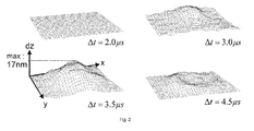
- Fig. 2 By way of example, according to the invention, certain deformation profiles can be seen on a sample phantom.
- the underlying measurement setup corresponds in principle to that of Pedrini et al., In which additionally a pulsed excitation laser is integrated.
- ⁇ 1064 nm is chosen as the wavelength of the excitation laser with a pulse duration of 20 ns and a pulse energy of about 20 mJ.
- the observation laser light the wavelength 532 nm with the pulse duration 1 ns and the coherence length 3 mm is used.
- About a ninth of the intensity of the observation laser is reflected before the phantom as a reference beam and guided to the camera.
- the camera has the following characteristics: Progressive Scan 1 "CCD sensor with 1600 x 1200 pixels, pixel size 7.4 x 7.4 ⁇ m 2 , maximum frame rate 35 fps.
- the sample phantom is a cube of about one centimeter edge length.
- the matrix material here is transparent silicone for visible light, in the interior of which there is a spherical light absorber (diameter about 2 mm) made of black silicone with high optical absorption.
- the side of the cube which is irradiated with the illumination light is white with a thin layer Silicone coated.
- White silicone has a high optical scattering coefficient. This increases the backscatter and prevents deep penetration of the illumination radiation into the matrix material which is transparent in this model.
- Samples tested with PAT often do not have ideal properties for DP-ESPI measurement. Since the sample material for the excitation light should have a high penetration depth, it is not always possible to provide an observation laser light which is scattered only at the sample surface (the measurement surface). Rather, it is to be expected with a limited penetration into a - often only a few micrometers thick - layer under the measuring surface from which then backscattered light can reach the detector. It may be advantageous for the DP-ESPI measurement to cover the measuring surface with a layer containing scattering particles, which promotes primarily the scattering of the observation laser light. For this purpose, preferably ceramic particles, for example a titanium oxide, into consideration.
- excitation and observation light are irradiated on different sides of the cube.
- the camera faces the cube side illuminated with observation light and images it off.
- the excitation light is irradiated, which penetrates into the transparent matrix material to the absorber and initiates the pressure wave emission.
- Measurement results of the deformation of the sample phantom at selected times 2 ⁇ s, 3 ⁇ s, 3.5 ⁇ s and 4.5 ⁇ s after irradiation of excitation light are in Fig. 2 shown.
- the absorber ball in the phantom is arranged at a distance of about 3 mm from the cube surface facing the camera.
- the speed of sound in silicon (about 1 km / s) results in the expected time of oscillation of the surface at about 3 ⁇ s after excitation. In the first part of the figure after 2 ⁇ s, a flat surface can be seen, so there is no discernable deformation at this time.
- the invention adopts the known double pulse ESPI for use in photoacoustic tomography. This is achieved by the addition of a third light pulse, which serves to excite the sample to pressure oscillations and as such is not detected directly by the camera whose known time of sending between the two observation laser pulses, however, defines a time index, which is assigned to a determinable deformation profile appropriate.
- a sequence of deformation profiles can be determined which approximates the true deformation of the measurement surface after the application of a single excitation pulse.
- the invention also allows the technical acquisition of all necessary measurement data for areas of the order of square centimeters within a few seconds or even within 200 milliseconds.
- the acquired data are to be processed and submitted to a PAT reconstruction in order to conclude and / or represent the position of the target structures.
- the fast completion of data collection avoids disturbances and measurement artifacts, especially if they were due to intrinsic movements or internal movements of the sample.
- triple pulse PAT The invention may be referred to as "triple pulse PAT". It represents a very expedient development of the known PAT method by incorporating the use of modern high-speed cameras into the PAT method, thus fundamentally redefining the currently existing problem of slow data acquisition.
Landscapes
- Health & Medical Sciences (AREA)
- Life Sciences & Earth Sciences (AREA)
- Physics & Mathematics (AREA)
- Medical Informatics (AREA)
- Surgery (AREA)
- Biophysics (AREA)
- Pathology (AREA)
- Engineering & Computer Science (AREA)
- Biomedical Technology (AREA)
- Heart & Thoracic Surgery (AREA)
- Veterinary Medicine (AREA)
- Molecular Biology (AREA)
- Public Health (AREA)
- Animal Behavior & Ethology (AREA)
- General Health & Medical Sciences (AREA)
- Radiology & Medical Imaging (AREA)
- Nuclear Medicine, Radiotherapy & Molecular Imaging (AREA)
- Acoustics & Sound (AREA)
- General Physics & Mathematics (AREA)
- Investigating Or Analyzing Materials By The Use Of Ultrasonic Waves (AREA)
- Investigating Or Analysing Materials By Optical Means (AREA)
- Ultra Sonic Daignosis Equipment (AREA)
Priority Applications (2)
| Application Number | Priority Date | Filing Date | Title |
|---|---|---|---|
| EP13157616.7A EP2774530B1 (fr) | 2013-03-04 | 2013-03-04 | Procédé de tomographie photoacoustique |
| US14/195,059 US9506742B2 (en) | 2013-03-04 | 2014-03-03 | Method for photoacoustic tomograpy |
Applications Claiming Priority (1)
| Application Number | Priority Date | Filing Date | Title |
|---|---|---|---|
| EP13157616.7A EP2774530B1 (fr) | 2013-03-04 | 2013-03-04 | Procédé de tomographie photoacoustique |
Publications (2)
| Publication Number | Publication Date |
|---|---|
| EP2774530A1 true EP2774530A1 (fr) | 2014-09-10 |
| EP2774530B1 EP2774530B1 (fr) | 2019-07-10 |
Family
ID=47912936
Family Applications (1)
| Application Number | Title | Priority Date | Filing Date |
|---|---|---|---|
| EP13157616.7A Active EP2774530B1 (fr) | 2013-03-04 | 2013-03-04 | Procédé de tomographie photoacoustique |
Country Status (2)
| Country | Link |
|---|---|
| US (1) | US9506742B2 (fr) |
| EP (1) | EP2774530B1 (fr) |
Families Citing this family (17)
| Publication number | Priority date | Publication date | Assignee | Title |
|---|---|---|---|---|
| US10117583B2 (en) | 2014-10-22 | 2018-11-06 | illumiSonics, Inc. | Photoacoustic remote sensing (PARS) |
| RU2610550C1 (ru) * | 2015-09-14 | 2017-02-13 | Шлюмберже Текнолоджи Б.В. | Способ определения температурного коэффициента линейного расширения материала и устройство для его осуществления |
| DE102015118856B3 (de) * | 2015-11-04 | 2016-08-18 | Netzsch-Gerätebau GmbH | Verfahren und Vorrichtung zur photothermischen Untersuchung einer Probe |
| US10327646B2 (en) | 2016-02-02 | 2019-06-25 | Illumisonics Inc. | Non-interferometric photoacoustic remote sensing (NI-PARS) |
| JP6451695B2 (ja) * | 2016-06-02 | 2019-01-16 | 株式会社島津製作所 | 欠陥検査方法及び欠陥検査装置 |
| US10627338B2 (en) | 2017-03-23 | 2020-04-21 | Illumisonics Inc. | Camera-based photoacoustic remote sensing (C-PARS) |
| IL253862B (en) * | 2017-08-06 | 2021-04-29 | Elbit Systems Land & C4I Ltd | Photoacoustic excitation sensing enhanced by cross-correlated unfocused speckle images |
| IL261039B (en) | 2018-08-07 | 2020-10-29 | Elbit Systems Land & C4I Ltd | A two-stage system and method for sensing photoacoustic excitation |
| US10687789B1 (en) | 2019-02-19 | 2020-06-23 | Endra Life Sciences Inc. | Method and system for reconstructing a thermoacoustic image |
| JP2022524857A (ja) | 2019-03-15 | 2022-05-10 | イルミソニックス インコーポレイテッド | 単一光源光音響リモートセンシング(ss-pars) |
| WO2020204817A1 (fr) * | 2019-03-29 | 2020-10-08 | Agency For Science, Technology And Research | Procédé et système de test non destructif sans contact |
| US20210076944A1 (en) * | 2019-09-18 | 2021-03-18 | Massachusetts Institute Of Technology | System and method for non-contact ultrasound image reconstruction |
| CA3161943A1 (fr) | 2019-12-19 | 2021-06-24 | Parsin Haji Reza | Detection photoacoustique a distance (pars) et procedes d'utilisation associes |
| US11786128B2 (en) | 2020-06-18 | 2023-10-17 | Illumisonics Inc. | PARS imaging methods |
| US11122978B1 (en) | 2020-06-18 | 2021-09-21 | Illumisonics Inc. | PARS imaging methods |
| JP7428597B2 (ja) * | 2020-06-18 | 2024-02-06 | 株式会社アドバンテスト | 光超音波測定装置、方法、プログラム、記録媒体 |
| EP4662479A1 (fr) | 2023-02-08 | 2025-12-17 | Illumisonics Inc. | Système de détection à distance d'absorption de photons pour évaluation histologique de tissus |
Family Cites Families (3)
| Publication number | Priority date | Publication date | Assignee | Title |
|---|---|---|---|---|
| US9999354B2 (en) * | 2011-01-21 | 2018-06-19 | National Research Council Of Canada | Biological tissue inspection method and system |
| US9442095B2 (en) * | 2011-06-15 | 2016-09-13 | Northwestern University | Optical coherence photoacoustic microscopy |
| US9833148B2 (en) * | 2011-08-11 | 2017-12-05 | University of Washington Through its Center For Commerciallzation | Methods and systems for integrated imaging using optical coherence tomography and photoacoustic imaging |
-
2013
- 2013-03-04 EP EP13157616.7A patent/EP2774530B1/fr active Active
-
2014
- 2014-03-03 US US14/195,059 patent/US9506742B2/en active Active
Non-Patent Citations (5)
| Title |
|---|
| "Optoacoustic imaging based on the interferometric measurement of surface displacement", JOURNAL OF BIOMEDICAL OPTICS, vol. 12, no. 6, 2007, pages 064001 FF |
| ARBEIT VON PEDRINI ET AL.: "Double-pulse electronic speckle interferometry", JOURNAL OF MODERN OPTICS, vol. 40, no. 1, 1993, pages 89 - 96 |
| BJÖRN KEMPER ET AL: "Endoscopic Double-Pulse Electronic-Speckle-Pattern Interferometer for Technical and Medical Intracavity Inspection", APPLIED OPTICS, vol. 39, no. 22, 1 August 2000 (2000-08-01), pages 3899, XP055072671, ISSN: 0003-6935, DOI: 10.1364/AO.39.003899 * |
| CRISTINA TRILLO ET AL: "Numerical reconstruction of acoustic bulk waves in aluminium from TV holography surface displacement measurements", PROCEEDINGS OF SPIE, vol. 7098, 4 June 2008 (2008-06-04), pages 70980G - 70980G-9, XP055072227, ISSN: 0277-786X, DOI: 10.1117/12.802984 * |
| ZHENHENG LIN ET AL: "Study of photoacoustic imaging based on all-optical detection", PROCEEDINGS OF SPIE, vol. 7160, 3 December 2008 (2008-12-03), pages 71602K - 71602K-8, XP055072210, ISSN: 0277-786X, DOI: 10.1117/12.807018 * |
Also Published As
| Publication number | Publication date |
|---|---|
| US9506742B2 (en) | 2016-11-29 |
| US20140247456A1 (en) | 2014-09-04 |
| EP2774530B1 (fr) | 2019-07-10 |
Similar Documents
| Publication | Publication Date | Title |
|---|---|---|
| EP2774530B1 (fr) | Procédé de tomographie photoacoustique | |
| DE102011018603B3 (de) | Verfahren zur optischen Tomographie | |
| EP2702935A1 (fr) | Système et procédé destinés à la tomographie de cohérence optique ainsi que l'élément de positionnement | |
| EP3335001B1 (fr) | Procédé et dispositif pour photographier au moins une surface de coupe à l'intérieur d'un objet diffusant la lumière | |
| DE3422144A1 (de) | Geraet zur darstellung flaechenhafter bereiche des menschlichen auges | |
| EP0772768A1 (fr) | Procede et appareil permettant de caracteriser de maniere optique la structure et la composition d'un echantillon dispersif | |
| WO2012136340A1 (fr) | Procédé et système de tomographie optique cohérente | |
| EP3304025B1 (fr) | Procédé et dispositif de détermination de données de surface et/ou de données de mesure d'une surface d'un objet au moins partiellement transparent | |
| EP2563208B1 (fr) | Dispositif avec système oct (tomographie par cohérence optique) pour l'examen et le traitement d'un tissu vivant sous chauffage par absorption d'un rayonnement électromagnétique | |
| WO2012136338A1 (fr) | Procédé et système de tomographie optique cohérente | |
| WO2008040771A2 (fr) | Procédé et arrangement pour caractériser un objet avec de la lumière et un mouvement de cisaillement | |
| DE2517628B2 (fr) | ||
| DE102012002127B3 (de) | Verfahren und Vorrichtung zur Erkennung von Oberflächenrissen | |
| AT520007B1 (de) | Thermographieverfahren | |
| EP4479236B1 (fr) | Appareil d'impression 3d et procédé d'impression 3d permettant de fabriquer une pièce à usiner | |
| WO2003046472A2 (fr) | Procede et dispositif pour detecter la forme d'un objet tridimensionnel | |
| DE602005004417T2 (de) | Vorrichtung zur bestimmung eines brechungsindex in einer grossen anzahl von punkten einer physischen umgebung, beispielsweise einem teil eines menschlichen oder tierischen körpers | |
| WO2021151792A1 (fr) | Procédé et dispositif de caractérisation d'un champ lumineux cohérent en amplitude et en phase | |
| DE102006051868B4 (de) | Dreidimensionale Einzelschussholographie | |
| DE102017201795B4 (de) | Verfahren zur Bestimmung des Transmissionsgrades eines optischen Systems mit einem Messobjekt, bei dem es sich um mindestens einen Spiegel einer EUV-Projektionsbelichtungsanlage handelt, in Abhängigkeit einer Mehrzahl vorgegebener Parameter | |
| EP3581879B1 (fr) | Dispositif et procédé de mesure interférométrique d'une surface d'un echantillon en mouvement | |
| WO2007137848A1 (fr) | Dispositif et procédé de représentation de la structure interne d'un corps au moyen d'un diagnostic par ultrasons induit par un laser | |
| DE19740251C1 (de) | Verfahren und Vorrichtung zur flächenhaften Erfassung transienter mechanischer Veränderungen eines Objektes mit einem Interferometer | |
| DE102021205147A1 (de) | Vorrichtung zur Röntgenbilderzeugung | |
| DE102020201536A1 (de) | Verfahren und Vorrichtung zum berührungslosen Vermessen einer Objektoberfläche |
Legal Events
| Date | Code | Title | Description |
|---|---|---|---|
| PUAI | Public reference made under article 153(3) epc to a published international application that has entered the european phase |
Free format text: ORIGINAL CODE: 0009012 |
|
| 17P | Request for examination filed |
Effective date: 20130304 |
|
| AK | Designated contracting states |
Kind code of ref document: A1 Designated state(s): AL AT BE BG CH CY CZ DE DK EE ES FI FR GB GR HR HU IE IS IT LI LT LU LV MC MK MT NL NO PL PT RO RS SE SI SK SM TR |
|
| AX | Request for extension of the european patent |
Extension state: BA ME |
|
| R17P | Request for examination filed (corrected) |
Effective date: 20150304 |
|
| RBV | Designated contracting states (corrected) |
Designated state(s): AL AT BE BG CH CY CZ DE DK EE ES FI FR GB GR HR HU IE IS IT LI LT LU LV MC MK MT NL NO PL PT RO RS SE SI SK SM TR |
|
| RAP1 | Party data changed (applicant data changed or rights of an application transferred) |
Owner name: MEDIZINISCHES LASERZENTRUM LUEBECK GMBH |
|
| GRAP | Despatch of communication of intention to grant a patent |
Free format text: ORIGINAL CODE: EPIDOSNIGR1 |
|
| STAA | Information on the status of an ep patent application or granted ep patent |
Free format text: STATUS: GRANT OF PATENT IS INTENDED |
|
| INTG | Intention to grant announced |
Effective date: 20190319 |
|
| GRAS | Grant fee paid |
Free format text: ORIGINAL CODE: EPIDOSNIGR3 |
|
| GRAA | (expected) grant |
Free format text: ORIGINAL CODE: 0009210 |
|
| STAA | Information on the status of an ep patent application or granted ep patent |
Free format text: STATUS: THE PATENT HAS BEEN GRANTED |
|
| AK | Designated contracting states |
Kind code of ref document: B1 Designated state(s): AL AT BE BG CH CY CZ DE DK EE ES FI FR GB GR HR HU IE IS IT LI LT LU LV MC MK MT NL NO PL PT RO RS SE SI SK SM TR |
|
| REG | Reference to a national code |
Ref country code: GB Ref legal event code: FG4D Free format text: NOT ENGLISH |
|
| REG | Reference to a national code |
Ref country code: CH Ref legal event code: EP Ref country code: AT Ref legal event code: REF Ref document number: 1152681 Country of ref document: AT Kind code of ref document: T Effective date: 20190715 |
|
| REG | Reference to a national code |
Ref country code: DE Ref legal event code: R096 Ref document number: 502013013121 Country of ref document: DE |
|
| REG | Reference to a national code |
Ref country code: IE Ref legal event code: FG4D Free format text: LANGUAGE OF EP DOCUMENT: GERMAN |
|
| REG | Reference to a national code |
Ref country code: NL Ref legal event code: MP Effective date: 20190710 |
|
| REG | Reference to a national code |
Ref country code: LT Ref legal event code: MG4D |
|
| PG25 | Lapsed in a contracting state [announced via postgrant information from national office to epo] |
Ref country code: LT Free format text: LAPSE BECAUSE OF FAILURE TO SUBMIT A TRANSLATION OF THE DESCRIPTION OR TO PAY THE FEE WITHIN THE PRESCRIBED TIME-LIMIT Effective date: 20190710 Ref country code: PT Free format text: LAPSE BECAUSE OF FAILURE TO SUBMIT A TRANSLATION OF THE DESCRIPTION OR TO PAY THE FEE WITHIN THE PRESCRIBED TIME-LIMIT Effective date: 20191111 Ref country code: NL Free format text: LAPSE BECAUSE OF FAILURE TO SUBMIT A TRANSLATION OF THE DESCRIPTION OR TO PAY THE FEE WITHIN THE PRESCRIBED TIME-LIMIT Effective date: 20190710 Ref country code: FI Free format text: LAPSE BECAUSE OF FAILURE TO SUBMIT A TRANSLATION OF THE DESCRIPTION OR TO PAY THE FEE WITHIN THE PRESCRIBED TIME-LIMIT Effective date: 20190710 Ref country code: NO Free format text: LAPSE BECAUSE OF FAILURE TO SUBMIT A TRANSLATION OF THE DESCRIPTION OR TO PAY THE FEE WITHIN THE PRESCRIBED TIME-LIMIT Effective date: 20191010 Ref country code: BG Free format text: LAPSE BECAUSE OF FAILURE TO SUBMIT A TRANSLATION OF THE DESCRIPTION OR TO PAY THE FEE WITHIN THE PRESCRIBED TIME-LIMIT Effective date: 20191010 Ref country code: SE Free format text: LAPSE BECAUSE OF FAILURE TO SUBMIT A TRANSLATION OF THE DESCRIPTION OR TO PAY THE FEE WITHIN THE PRESCRIBED TIME-LIMIT Effective date: 20190710 Ref country code: HR Free format text: LAPSE BECAUSE OF FAILURE TO SUBMIT A TRANSLATION OF THE DESCRIPTION OR TO PAY THE FEE WITHIN THE PRESCRIBED TIME-LIMIT Effective date: 20190710 |
|
| PG25 | Lapsed in a contracting state [announced via postgrant information from national office to epo] |
Ref country code: IS Free format text: LAPSE BECAUSE OF FAILURE TO SUBMIT A TRANSLATION OF THE DESCRIPTION OR TO PAY THE FEE WITHIN THE PRESCRIBED TIME-LIMIT Effective date: 20191110 Ref country code: LV Free format text: LAPSE BECAUSE OF FAILURE TO SUBMIT A TRANSLATION OF THE DESCRIPTION OR TO PAY THE FEE WITHIN THE PRESCRIBED TIME-LIMIT Effective date: 20190710 Ref country code: RS Free format text: LAPSE BECAUSE OF FAILURE TO SUBMIT A TRANSLATION OF THE DESCRIPTION OR TO PAY THE FEE WITHIN THE PRESCRIBED TIME-LIMIT Effective date: 20190710 Ref country code: GR Free format text: LAPSE BECAUSE OF FAILURE TO SUBMIT A TRANSLATION OF THE DESCRIPTION OR TO PAY THE FEE WITHIN THE PRESCRIBED TIME-LIMIT Effective date: 20191011 Ref country code: AL Free format text: LAPSE BECAUSE OF FAILURE TO SUBMIT A TRANSLATION OF THE DESCRIPTION OR TO PAY THE FEE WITHIN THE PRESCRIBED TIME-LIMIT Effective date: 20190710 Ref country code: ES Free format text: LAPSE BECAUSE OF FAILURE TO SUBMIT A TRANSLATION OF THE DESCRIPTION OR TO PAY THE FEE WITHIN THE PRESCRIBED TIME-LIMIT Effective date: 20190710 |
|
| PG25 | Lapsed in a contracting state [announced via postgrant information from national office to epo] |
Ref country code: TR Free format text: LAPSE BECAUSE OF FAILURE TO SUBMIT A TRANSLATION OF THE DESCRIPTION OR TO PAY THE FEE WITHIN THE PRESCRIBED TIME-LIMIT Effective date: 20190710 |
|
| PG25 | Lapsed in a contracting state [announced via postgrant information from national office to epo] |
Ref country code: DK Free format text: LAPSE BECAUSE OF FAILURE TO SUBMIT A TRANSLATION OF THE DESCRIPTION OR TO PAY THE FEE WITHIN THE PRESCRIBED TIME-LIMIT Effective date: 20190710 Ref country code: EE Free format text: LAPSE BECAUSE OF FAILURE TO SUBMIT A TRANSLATION OF THE DESCRIPTION OR TO PAY THE FEE WITHIN THE PRESCRIBED TIME-LIMIT Effective date: 20190710 Ref country code: PL Free format text: LAPSE BECAUSE OF FAILURE TO SUBMIT A TRANSLATION OF THE DESCRIPTION OR TO PAY THE FEE WITHIN THE PRESCRIBED TIME-LIMIT Effective date: 20190710 Ref country code: IT Free format text: LAPSE BECAUSE OF FAILURE TO SUBMIT A TRANSLATION OF THE DESCRIPTION OR TO PAY THE FEE WITHIN THE PRESCRIBED TIME-LIMIT Effective date: 20190710 Ref country code: RO Free format text: LAPSE BECAUSE OF FAILURE TO SUBMIT A TRANSLATION OF THE DESCRIPTION OR TO PAY THE FEE WITHIN THE PRESCRIBED TIME-LIMIT Effective date: 20190710 |
|
| PG25 | Lapsed in a contracting state [announced via postgrant information from national office to epo] |
Ref country code: SM Free format text: LAPSE BECAUSE OF FAILURE TO SUBMIT A TRANSLATION OF THE DESCRIPTION OR TO PAY THE FEE WITHIN THE PRESCRIBED TIME-LIMIT Effective date: 20190710 Ref country code: CZ Free format text: LAPSE BECAUSE OF FAILURE TO SUBMIT A TRANSLATION OF THE DESCRIPTION OR TO PAY THE FEE WITHIN THE PRESCRIBED TIME-LIMIT Effective date: 20190710 Ref country code: SK Free format text: LAPSE BECAUSE OF FAILURE TO SUBMIT A TRANSLATION OF THE DESCRIPTION OR TO PAY THE FEE WITHIN THE PRESCRIBED TIME-LIMIT Effective date: 20190710 Ref country code: IS Free format text: LAPSE BECAUSE OF FAILURE TO SUBMIT A TRANSLATION OF THE DESCRIPTION OR TO PAY THE FEE WITHIN THE PRESCRIBED TIME-LIMIT Effective date: 20200224 |
|
| REG | Reference to a national code |
Ref country code: DE Ref legal event code: R097 Ref document number: 502013013121 Country of ref document: DE |
|
| PLBE | No opposition filed within time limit |
Free format text: ORIGINAL CODE: 0009261 |
|
| STAA | Information on the status of an ep patent application or granted ep patent |
Free format text: STATUS: NO OPPOSITION FILED WITHIN TIME LIMIT |
|
| PG2D | Information on lapse in contracting state deleted |
Ref country code: IS |
|
| 26N | No opposition filed |
Effective date: 20200603 |
|
| PG25 | Lapsed in a contracting state [announced via postgrant information from national office to epo] |
Ref country code: SI Free format text: LAPSE BECAUSE OF FAILURE TO SUBMIT A TRANSLATION OF THE DESCRIPTION OR TO PAY THE FEE WITHIN THE PRESCRIBED TIME-LIMIT Effective date: 20190710 |
|
| PG25 | Lapsed in a contracting state [announced via postgrant information from national office to epo] |
Ref country code: MC Free format text: LAPSE BECAUSE OF FAILURE TO SUBMIT A TRANSLATION OF THE DESCRIPTION OR TO PAY THE FEE WITHIN THE PRESCRIBED TIME-LIMIT Effective date: 20190710 |
|
| REG | Reference to a national code |
Ref country code: CH Ref legal event code: PL |
|
| REG | Reference to a national code |
Ref country code: BE Ref legal event code: MM Effective date: 20200331 |
|
| PG25 | Lapsed in a contracting state [announced via postgrant information from national office to epo] |
Ref country code: LU Free format text: LAPSE BECAUSE OF NON-PAYMENT OF DUE FEES Effective date: 20200304 |
|
| PG25 | Lapsed in a contracting state [announced via postgrant information from national office to epo] |
Ref country code: LI Free format text: LAPSE BECAUSE OF NON-PAYMENT OF DUE FEES Effective date: 20200331 Ref country code: CH Free format text: LAPSE BECAUSE OF NON-PAYMENT OF DUE FEES Effective date: 20200331 Ref country code: IE Free format text: LAPSE BECAUSE OF NON-PAYMENT OF DUE FEES Effective date: 20200304 |
|
| PG25 | Lapsed in a contracting state [announced via postgrant information from national office to epo] |
Ref country code: BE Free format text: LAPSE BECAUSE OF NON-PAYMENT OF DUE FEES Effective date: 20200331 |
|
| REG | Reference to a national code |
Ref country code: AT Ref legal event code: MM01 Ref document number: 1152681 Country of ref document: AT Kind code of ref document: T Effective date: 20200304 |
|
| PG25 | Lapsed in a contracting state [announced via postgrant information from national office to epo] |
Ref country code: AT Free format text: LAPSE BECAUSE OF NON-PAYMENT OF DUE FEES Effective date: 20200304 |
|
| PG25 | Lapsed in a contracting state [announced via postgrant information from national office to epo] |
Ref country code: MT Free format text: LAPSE BECAUSE OF FAILURE TO SUBMIT A TRANSLATION OF THE DESCRIPTION OR TO PAY THE FEE WITHIN THE PRESCRIBED TIME-LIMIT Effective date: 20190710 Ref country code: CY Free format text: LAPSE BECAUSE OF FAILURE TO SUBMIT A TRANSLATION OF THE DESCRIPTION OR TO PAY THE FEE WITHIN THE PRESCRIBED TIME-LIMIT Effective date: 20190710 |
|
| PG25 | Lapsed in a contracting state [announced via postgrant information from national office to epo] |
Ref country code: MK Free format text: LAPSE BECAUSE OF FAILURE TO SUBMIT A TRANSLATION OF THE DESCRIPTION OR TO PAY THE FEE WITHIN THE PRESCRIBED TIME-LIMIT Effective date: 20190710 |
|
| PGFP | Annual fee paid to national office [announced via postgrant information from national office to epo] |
Ref country code: DE Payment date: 20250320 Year of fee payment: 13 |
|
| PGFP | Annual fee paid to national office [announced via postgrant information from national office to epo] |
Ref country code: FR Payment date: 20250312 Year of fee payment: 13 |
|
| PGFP | Annual fee paid to national office [announced via postgrant information from national office to epo] |
Ref country code: GB Payment date: 20250312 Year of fee payment: 13 |