EP2774401B1 - Vorrichtung für mobile kommunikation - Google Patents
Vorrichtung für mobile kommunikation Download PDFInfo
- Publication number
- EP2774401B1 EP2774401B1 EP12780193.4A EP12780193A EP2774401B1 EP 2774401 B1 EP2774401 B1 EP 2774401B1 EP 12780193 A EP12780193 A EP 12780193A EP 2774401 B1 EP2774401 B1 EP 2774401B1
- Authority
- EP
- European Patent Office
- Prior art keywords
- mobile
- authentication
- transceiver
- function
- controller
- Prior art date
- Legal status (The legal status is an assumption and is not a legal conclusion. Google has not performed a legal analysis and makes no representation as to the accuracy of the status listed.)
- Active
Links
Images

Classifications
-
- G—PHYSICS
- G06—COMPUTING OR CALCULATING; COUNTING
- G06F—ELECTRIC DIGITAL DATA PROCESSING
- G06F21/00—Security arrangements for protecting computers, components thereof, programs or data against unauthorised activity
- G06F21/30—Authentication, i.e. establishing the identity or authorisation of security principals
- G06F21/31—User authentication
- G06F21/34—User authentication involving the use of external additional devices, e.g. dongles or smart cards
- G06F21/35—User authentication involving the use of external additional devices, e.g. dongles or smart cards communicating wirelessly
-
- H—ELECTRICITY
- H04—ELECTRIC COMMUNICATION TECHNIQUE
- H04L—TRANSMISSION OF DIGITAL INFORMATION, e.g. TELEGRAPHIC COMMUNICATION
- H04L63/00—Network architectures or network communication protocols for network security
- H04L63/08—Network architectures or network communication protocols for network security for authentication of entities
- H04L63/0853—Network architectures or network communication protocols for network security for authentication of entities using an additional device, e.g. smartcard, SIM or a different communication terminal
-
- H—ELECTRICITY
- H04—ELECTRIC COMMUNICATION TECHNIQUE
- H04W—WIRELESS COMMUNICATION NETWORKS
- H04W12/00—Security arrangements; Authentication; Protecting privacy or anonymity
- H04W12/06—Authentication
- H04W12/068—Authentication using credential vaults, e.g. password manager applications or one time password [OTP] applications
Definitions
- the invention relates to a mobile device comprising a transceiver for mobile communication and a controller configured to execute an authentication function for authenticating a registered user of the device.
- WO 2004/036513 A1 dicloses a dongle which controls communication between a SIM, e.g. GSM cellular telephone system, and a computer.
- the dongle has a first coupling means for coupling to SIM and second coupling means for coupling to PC.
- the dongle with the sim is used to authenticate the user to the PC transaction; and charging the user.
- WO 98/25371 A1 discloses a mobile device of the type indicated above, wherein the authentication function includes prompting the user to confirm the transaction request.
- US 2006/288233 A1 discloses a mobile device with a biometric authentication function.
- WO 2007/072001 A1 discloses an authentication method and a mobile device wherein an authentication device responds to the transmission of a user identification with sending an authentication token to a terminal from which the transaction has been requested.
- This token may for example be encoded in a digital image to be displayed on a display of the terminal.
- the authentication function in the mobile device is configured to capture this digital image and send it back to the authentication device via the mobile communication channel.
- the authentication method assures that no third party can fake the identification data of this user and perform any transactions in his place.
- the mobile device has only a single operating element, the functionality of said single operating element is limited to activating and deactivating the authentication function, said authentication function consists in having the transceiver logged-on to a mobile communications network and enabling a detection of an active state and/or a location of the mobile device via the mobile network, and the operating element and the transceiver constitute the only data input and output ports of the controller.
- This device can be used, for example, for an authentication method wherein the authentication function that is implemented in the mobile device is normally inactive and is activated by the user only preliminarily for the transaction, and wherein the authentication device authenticates the user to a transaction only when a predetermined time relation exists between the transmission of the user identification and the active state of authentication function.
- the complexity of the authentication function can be reduced significantly.
- all that has to be required from the authentication function is to permit the authentication device to detect whether or not this function is active.
- the only activity that is required from the user for authentication purposes is to activate the authentication function at a suitable timing for the transaction. Once the active state of the authentication function has been detected, this function is returned into the inactive state, either automatically or manually by operating the operating element once again.
- the "predetermined time relation" may imply that the authentication function is active at the moment at which the user identification is sent from the terminal.
- the predetermined time relation may imply that the authentication function is activated within a certain (preferably short) time window after the transmission of the user identification or, conversely, that the user identification is transmitted within a specified time window after the authentication device has detected that the authentication function is active.
- the authentication function Since the authentication function is normally inactive, the authentication will almost certainly fail when a third party fraudulently identifies itself as the user in order to initiate a transaction. Then, the authentication would be successful only in the very unlikely event that the true user happens to activate the authentication function of his mobile device just in the right moment. Even in this unlikely case the fraud could be detected because the user will only activate the authentication function when he wants to make a transaction himself. Consequently, the authentication device would detect a coincidence between one activation of the authentication function and two transaction requests (normally launched from different terminals), and this would cause the authentication device to have the transactions denied or reversed. Thus, notwithstanding the low complexity, the method according to the invention offers a high level of security.
- the authentication device may check whether there is a predetermined spatial relation between the mobile device and the terminal.
- the mobile device does not have to have any specific hardware for capturing or outputting information. All that is required from the mobile device is that it can be activated for a certain (preferably short) period of time and is capable of connecting to a mobile communications network where it has an address that is linked to the identification data of the user, so that the authentication device, when it receives the user identification from the terminal, is capable of checking whether the authentication function of the mobile device with the associated address is active. To that end, it is not even necessary that there is any actual communication between the authentication device and the mobile device.
- the activation of the authentication function may just consist of activating that transceiver, so that it connects to the nearest Base Station Subsystem (BSS) of the mobile network.
- BSS Base Station Subsystem
- the mobile device will be identified by its device identifier (IMSI), and information on the active state of the mobile device and on the GSM-cell in which it is located will be entered into a Home Location Register (HLR) of the mobile network.
- IMSI device identifier
- HLR Home Location Register
- the authentication device may check the active or inactive state of the mobile device and may locate the same just by querying the HLR.
- the mobile device may have a plurality of mobile addresses (e. g. mobile telephone numbers) and may even be capable of communicating via a plurality of different mobile networks.
- each mobile address is assigned to a different type of transaction (e. g. one telephone number for authenticating bank transactions and another one for authenticating access to a data network), and the authentication function or a plurality of authentication functions are adapted to be activated and deactivated separately for each type of transaction.
- a plurality of mobile addresses may be assigned to one and the same type of transaction, and the mobile device and the authentication device use identical algorithms for changing from time to time the mobile address that is to be used for authentication purposes.
- the device according to the invention may have a positioning function permitting to locate the mobile device, and optionally a function for sending the detected location via the transceiver to the authentication device.
- the electronic components of the device are protected against both electronic and mechanical access.
- the device may also have a self-destruction function configured to be activated by an attempt of enforced access.
- the self-destruction function may be triggered by an event in which the body of the device is broken to expose the data processing system (chip) and may assure that, in that event, or the program code and the data are erased.
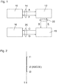
- a transaction terminal 10 communicates with a remote transaction partner 12, e.g. a bank, via a first communication channel 14 which may be a wireline or wireless channel.
- a mobile device 16 communicates with an authentication device 18 via a second communication channel 20 which preferably includes a wireless link, e.g. a mobile telephone network.
- the authentication device 18 may be installed in the premises of the transaction partner 12 or may be configured as a separate entity communicating with the transaction partner 12 via a third communication channel 22.
- the mobile device 16 is carried by a user who is registered as a subscriber to the mobile telephone network forming the communication channel 20.
- the authentication device 18 is formed by data processing hardware and software and includes a database that stores a user ID of the user and the mobile telephone number (or any another mobile address) of the mobile device 16 of that user.
- the user wants to make a bank transaction via the terminal 10.
- the user operates the terminal 10 and sends a transaction request to the transaction partner 12. That request includes a step A of transmitting the user-ID to the transaction partner 12.
- the transaction partner 12 forwards the user-ID to the authentication device 18.
- the authentication device 18 retrieves the mobile telephone number and/or the IMSI of the user and contacts the mobile device 16 or at least the mobile telephone network to check whether or not the mobile device 16 or a certain authentication function implemented therein is active (step C).
- the authentication device 18 sends an authentication signal to the transaction partner 12 (step E).
- the authentication signal preferably includes the user-ID that has been sent in step B and informs the transaction partner that this specific user is authenticated to the requested transaction.
- the transaction between the user and the transaction partner 12 will be performed via the terminal 10 (step F).
- Fig 2 shows a time diagram illustrating one embodiment of the authentication method that has been outlined above.
- the user who wants to request a transaction activates his mobile device 16.
- the sequence of steps A-B-C-D-E is performed to authenticate the user. Since, at this time, the mobile device 16 is actually active, the authentication is successful. Then, at a time t3, the mobile device 16 is deactivated either manually or automatically by a self-deactivation function implemented in the device 16. As another alternative, a command to deactivate the mobile device 16 may be sent by the authentication device 18 when the user has been authenticated successfully.
- the time interval from t1 to t3 in which the mobile device 16 is active will be relatively small, e.g. only a few minutes or seconds.
- the mobile device 16 or at least the authentication function thereof
- the authentication process may optionally include additional steps of communication between the mobile device 16 and the authentication device 18.
- Such communication protocols for authentication purposes are generally known in the art.
- the mobile device may use a pre-programmed algorithm to generate an identification code and send it to the authentication device.
- the pre-programmed algorithm is known to the authentication device and is used there to verify the identity of the mobile device, independently of its IMSI.
- the identification code may for example be a number from a list of "TAN" numbers that is stored in the mobile device, the algorithm being configured such that each number is used only once.
- the identification codes may be generated dynamically, possibly with use of data such as the current date or the time of the day.
- the identification code may be an encrypted password or an encrypted combination of a password with time and date data, the encryption being based on a dynamically varied encryption parameter that is sent from the authentication device.
- the authentication will be successful only when the authentication device finds the identification code to be valid. In any case, the authentication will be denied whenever it is found that the authentication function of the mobile device 16 is not active at the right time.
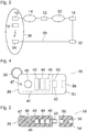
- Fig. 3 illustrates a communication scheme in which the first communication channel 14 and the third communication channel 22 are formed by the Internet, for example.
- the authentication device 18 is installed remote from the transaction partner 12 and is run by a Trusted Third Party that is independent from the transaction partner 12.
- the second communication channel 20 is formed by a mobile telephone network including a Home Location Register (HLR) 32 and a plurality of Base Station Subsystems (BSS) 34 only one of which has been shown in Fig. 7 and each of which serves one or more mobile telephone cells 36.
- HLR Home Location Register
- BSS Base Station Subsystems
- the authentication device 18 identifies the mobile cell 36 in which the device 16 is currently located, and the user is authenticated to the transaction only when the mobile device 16 is found to be located in the cell 36 that accommodates also the terminal 10 from which the transaction has been requested.
- a false authentication is possible only when the user-ID is sent from a certain terminal 10 at the right moment and, additionally, the mobile device 16 of the true user happens to be located in the vicinity of that terminal 10.
- LBS Location Based Services
- the mobile device 16 may include a GPS function, and the authentication function may be configured to send the current GPS coordinates of the mobile device 16 to the authentication device 18.
- Figs. 4 and 5 show an example of a mobile device 16 according to the invention that is dedicated to the authentication purpose.
- This device 16 has a body 38 which accommodates a wireless transceiver 40 (e.g. a mobile telephone transceiver) with an antenna 42, an electronic controller 44 (data processing system) a rechargeable battery 46, and a battery charge control lamp 47.
- a wireless transceiver 40 e.g. a mobile telephone transceiver
- an electronic controller 44 data processing system
- rechargeable battery 46 e.g. a rechargeable battery 46
- battery charge control lamp 47 e.g. a battery charge control lamp
- a device identifier (ISMI) is permanently stored in the controller 44 which may have the only function to activate and deactivate the transceiver 40 so that the latter may connect and identify itself to the nearest BSS 34.
- An ON-switch 48 (operating element) is formed in the surface of the body 38,.
- the ON-switch 48 may simply be formed by a button, so that the user may activate the authentication function (i.e. the transceiver 40) by pressing the button.
- the ON-switch may be formed by an input device for inputting some secret code (e. g. a PIN) or by a biometric sensor such as a fingerprint sensor or iris recognition sensor, so that the transceiver will be activated only when the identity of the user has been confirmed.
- a buzzer 49 is provided for giving an acoustic feedback when the authentication function has been activated successfully by pressing the ON-switch 48.
- the body 38 has relatively small dimensions and is attached to a key ring 50 so that it may conveniently be carried along at a bunch of keys of the user.
- a male socket 52 Projecting from one end of the body 38 is a male socket 52 (e.g. an USB socket or micro-USB socket) which is connected to the battery 46, so that the battery may be recharged by plugging the device 16 into a female USB socket of a computer, a mobile phone or the like.
- the male socket 52 is covered and protected by a removable cap 54.
- the cap 54 forms a female socket 56 that is open to the outside and is internally connected to another female socket 58 that accommodates the male socket 52.
- the battery 46 may also be recharged by plugging a male USB or micro-USB connector of a power source into the socket 56.
- the body 38 is a massive plastic body with the transceiver 40, the controller 44 and the battery 46 cast therein. Thus, physical access to these components, especially the transceiver 40 and the controller 44, is not possible without destroying the body 38.
- the controller 44 may include a memory with program code and data for more complex authentication functions, e. g. a function for generating and transmitting a device identification code, as has been described above.
- the controller has no electronic contacts that would provide a possibility to read-out the contents of the memory.
- the controller 44 especially the memory thereof, may be configured such that all stored contents are erased as soon as the body 38 is broken and someone tries to remove the controller therefrom.
- the authentication data that may be stored in the memory of the controller 44 are reliably protected against copying.
- Fig. 6 shows an example of a mobile device 16' that is dedicated only to authentication purposes but supports two different authentication procedures for two different types of transaction.
- the device 16' has two SIM cards 60, 60' (or other memory devices) which store different sets of access data.
- each of the SIM cards has its own mobile telephone number which may even belong to two different mobile networks.
- Each mobile telephone number is assigned to a different one of the types of transaction.
- the two mobile numbers may be registered in two different authentication devices or my be registered in the same authentication device along with information specifying the type of transaction for which they shall be used.
- the device 16' has two buttons 48 and 48' for selectively activating one of the two SIM cards 60, 60'.
- the user may specify the type of transaction he wants to perform by pressing either the button 48 or the button 48' in order to activate the related SIM card and, implicitly, the related authentication function.
- the controller 44 will then automatically deactivate the authentication function (SIM card) after a certain time interval.
- the device 16' may have a plurality of SIM cards (or other Mobile Network Identification Numbers such as IMSI, phone No. and the like) but only a single switch 48 for activating the authentication function. Then, a certain algorithm that is stored in the controller 44 is used for deciding which of the SIM cards is to be used, e.g. depending upon the date, the time of the day or the like. An identical algorithm is used in the authentication device 18, and a successful authentication is possible only when both the mobile device and the authentication device use the same contact data associated with the determined SIM card.
- SIM cards or other Mobile Network Identification Numbers such as IMSI, phone No. and the like
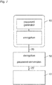
- Fig. 7 illustrates a useful modification that may be implemented in any of the authentication methods discussed above.
- the request for authentication sent from the terminal 10 to the transaction partner 12 will include not only the user ID but also a password showing that the user is actually entitled to the service he is requesting.
- this password is not transmitted via the first communication channel 14 but via the second or third communication channel. This reduces the risk of the combination of password and user ID being captured by tapping one of the communication channels.
- the mobile device includes a password generator 62 that generates a dynamically changing password according to a certain algorithm that is mirrored by the authentication device 18.
- the password sent via the communication channel 20 is encrypted.
- the decrypted password may then be passed on to the transaction partner 12.
- the password generated in the mobile device is a universal password that is used for each authentication process regardless of the transaction partner and the type of service involved. Then, based on information on the specific type of service, as transmitted from the transaction partner 12 in step B, if the authentication is successful, the authentication device 18 automatically converts the universal password into a specific password that is pertinent for the type of service.
Landscapes
- Engineering & Computer Science (AREA)
- Computer Security & Cryptography (AREA)
- Computer Networks & Wireless Communication (AREA)
- Signal Processing (AREA)
- Theoretical Computer Science (AREA)
- Computer Hardware Design (AREA)
- General Engineering & Computer Science (AREA)
- Computing Systems (AREA)
- Physics & Mathematics (AREA)
- General Physics & Mathematics (AREA)
- Software Systems (AREA)
- Mobile Radio Communication Systems (AREA)
- Telephone Function (AREA)
- Telephonic Communication Services (AREA)
Claims (15)
- Mobiles Gerät (16) mit einem Transceiver (40) für mobile Kommunikation und einer Steuereinrichtung (44), die dazu konfiguriert ist, eine Authentifizierungsfunktion zum Authentifizieren eines registrierten Benutzers des Gerätes auszuführen, dadurch gekennzeichnet, dass das Gerät (16) nur ein einziges Bedienungselement (48) aufweist, dessen Funktionalität darauf beschränkt ist, die Authentifizierungsfunktion zu aktivieren und zu deaktivieren, wobei diese Authentifizierungsfunktion darin besteht, dass der Transceiver sich in ein mobiles Kommunikationsnetzwerk einloggt und eine Detektion eines aktiven Zustands und/oder eine Ortung des mobilen Gerätes über das mobile Netzwerk zulässt, und dass das Bedienungselement (48) und der Transceiver (40) die einzigen Dateneingangsports und Datenausgangsports der Steuereinrichtung (44) bilden.
- Gerät nach Anspruch 1, mit einer wiederaufladbaren Batterie (46) und einem Verbinder (52) zum Verbinden der Batterie (46) mit einer Spannungsquelle.
- Gerät nach Anspruch 2, mit einer Anzeigeeinrichtung (47) zur Anzeige des Ladezustands der Batterie (46).
- Gerät nach Anspruch 2 oder 3, bei dem der Verbinder (52) ein USB- oder Mikro-USB-Verbinder ist.
- Gerät nach einem der Ansprüche 2 bis 4, bei dem der Verbinder (52) ein Stecker ist, der von einer lösbaren Kappe (54) bedeckt ist, die zwei Steckverbinderbuchsen (56, 58) aufweist, die es erlauben, den Stecker (52) über eine der Steckverbinderbuchsen (56) mit einer Spannungsquelle zu verbinden, während die andere Steckverbinderbuchse (58) an den Stecker (52) angekuppelt ist.
- Gerät nach einem der vorstehenden Ansprüche, bei dem die Steuereinrichtung (44) dazu konfiguriert ist, das Gerät nach einem bestimmten Zeitintervall nach der Betätigung des Bedienungselements (48) automatisch zu deaktivieren.
- Gerät nach Anspruch 6, bei dem die Authentifizierungsfunktion ausschließlich darin besteht, dass als Reaktion auf die Betätigung des Bedienungselements (48) der Transceiver (40) aktiviert wird.
- Gerät nach einem der Ansprüche 1 bis 6, mit einer Positionserkennungsfunktion zur drahtlosen Detektion der eigenen Position, wobei die Authentifizierungsfunktion eine Funktion des Sendens des detektierten Ortes über den Transceiver (40) einschließt.
- Gerät nach einem der vorstehenden Ansprüche, mit einem Gehäuse (38), das zumindest das Datenverarbeitungssystem (44) aufnimmt und einen zerstörungsfreien Zugang zu dem letzteren verhindert.
- Gerät nach Anspruch 8, mit einer Selbstzerstörungsfunktion, die dazu konfiguriert ist, durch den Versuch eines erzwungenen Zugriffs aktiviert zu werden.
- Mobiles Gerät (16') mit einem Transceiver (40) für mobile Kommunikation und einer Steuereinrichtung (44), die dazu konfiguriert ist, eine Vielzahl von Authentifizierungsfunktionen zur Authentifizierung eines registrierten Benutzers des Gerätes für verschiedene Arten von Transaktionen auszuführen, dadurch gekennzeichnet, dass das Gerät (16') nur Bedienungselemente (48, 48') aufweist, die dazu eingerichtet sind, die genannten Authentifizierungsfunktionen selektiv zu aktivieren, wobei jede dieser Authentifizierungsfunktionen darin besteht, dass sich der Transceiver mit einer bestimmten mobilen Adresse in ein mobiles Kommunikationsnetzwerk einloggt und eine Detektion eines aktiven Zustands und/oder eine Ortung des mobilen Gerätes über das mobile Netzwerk ermöglicht, und dass die Bedienungselemente (48) und der Transceiver (40) die einzigen Dateneingangsports und Datenausgangsports der Steuereinrichtung (44) bilden.
- Gerät nach einem der vorstehenden Ansprüche, mit einem Speicher zum Speichern eines Passworts, das über das mobile Netzwert zu senden ist.
- Gerät nach einem der Ansprüche 1 bis 11, mit einem Verarbeitungssystem zum Erzeugen eines Passworts, das über das mobile Netzwerk zu senden ist.
- Gerät nach einem der Ansprüche 1 bis 13, mit einer Speichereinrichtung (60, 60') für eine Vielzahl von mobilen Adressen, wobei die Steuereinrichtung (44) dazu konfiguriert ist, aus der Vielzahl der mobilen Adressen eine mobile Adresse in Übereinstimmung mit einem vorbestimmten Algorithmus auszuwählen.
- Gerät nach einem der Ansprüche 1 bis 14, mit einem akustischen Wandler (49) zum Bereitstellen eines akustischen Rückkopplungssignals bei Aktivierung und/oder Deaktivierung der Authentifizierungsfunktion.
Priority Applications (1)
| Application Number | Priority Date | Filing Date | Title |
|---|---|---|---|
| EP12780193.4A EP2774401B1 (de) | 2011-10-31 | 2012-10-30 | Vorrichtung für mobile kommunikation |
Applications Claiming Priority (3)
| Application Number | Priority Date | Filing Date | Title |
|---|---|---|---|
| EP11187280.0A EP2587854A1 (de) | 2011-10-31 | 2011-10-31 | Vorrichtung für mobile Kommunikation |
| PCT/EP2012/071502 WO2013064504A1 (en) | 2011-10-31 | 2012-10-30 | Device for mobile communication |
| EP12780193.4A EP2774401B1 (de) | 2011-10-31 | 2012-10-30 | Vorrichtung für mobile kommunikation |
Publications (2)
| Publication Number | Publication Date |
|---|---|
| EP2774401A1 EP2774401A1 (de) | 2014-09-10 |
| EP2774401B1 true EP2774401B1 (de) | 2018-07-18 |
Family
ID=47115960
Family Applications (2)
| Application Number | Title | Priority Date | Filing Date |
|---|---|---|---|
| EP11187280.0A Withdrawn EP2587854A1 (de) | 2011-10-31 | 2011-10-31 | Vorrichtung für mobile Kommunikation |
| EP12780193.4A Active EP2774401B1 (de) | 2011-10-31 | 2012-10-30 | Vorrichtung für mobile kommunikation |
Family Applications Before (1)
| Application Number | Title | Priority Date | Filing Date |
|---|---|---|---|
| EP11187280.0A Withdrawn EP2587854A1 (de) | 2011-10-31 | 2011-10-31 | Vorrichtung für mobile Kommunikation |
Country Status (6)
| Country | Link |
|---|---|
| US (1) | US9294921B2 (de) |
| EP (2) | EP2587854A1 (de) |
| CN (1) | CN103918293B (de) |
| CA (1) | CA2851693C (de) |
| RU (1) | RU2596587C2 (de) |
| WO (1) | WO2013064504A1 (de) |
Families Citing this family (7)
| Publication number | Priority date | Publication date | Assignee | Title |
|---|---|---|---|---|
| US9832646B2 (en) * | 2013-09-13 | 2017-11-28 | Network Kinetix, LLC | System and method for an automated system for continuous observation, audit and control of user activities as they occur within a mobile network |
| US10785645B2 (en) * | 2015-02-23 | 2020-09-22 | Apple Inc. | Techniques for dynamically supporting different authentication algorithms |
| US10248773B2 (en) | 2015-08-28 | 2019-04-02 | Gentex Corporation | Vehicle security accessory and methods of identity authentication |
| WO2019035048A1 (en) * | 2017-08-17 | 2019-02-21 | Gentex Corporation | IDENTIFICATION SYSTEM AND REMOTE TRANSMITTER ACTUATION METHOD |
| CN108022098A (zh) * | 2017-11-20 | 2018-05-11 | 胡研 | 一种交易方法、交易设备以及计算机可读存储介质 |
| US11013340B2 (en) | 2018-05-23 | 2021-05-25 | L&P Property Management Company | Pocketed spring assembly having dimensionally stabilizing substrate |
| US12369722B2 (en) | 2018-05-23 | 2025-07-29 | L&P Property Management Company | Method of disassembling pocketed spring assembly with dimensionally stabilizing substrate |
Family Cites Families (16)
| Publication number | Priority date | Publication date | Assignee | Title |
|---|---|---|---|---|
| US6088450A (en) * | 1996-04-17 | 2000-07-11 | Intel Corporation | Authentication system based on periodic challenge/response protocol |
| US5917913A (en) | 1996-12-04 | 1999-06-29 | Wang; Ynjiun Paul | Portable electronic authorization devices and methods therefor |
| US20040019571A1 (en) * | 2002-07-26 | 2004-01-29 | Intel Corporation | Mobile communication device with electronic token repository and method |
| GB2396707B (en) * | 2002-10-17 | 2004-11-24 | Vodafone Plc | Facilitating and authenticating transactions |
| WO2004036467A1 (en) * | 2002-10-17 | 2004-04-29 | Vodafone Group Plc. | Facilitating and authenticating transactions |
| US8548429B2 (en) * | 2004-03-08 | 2013-10-01 | Rafi Nehushtan | Cellular device security apparatus and method |
| CN1728565B (zh) * | 2004-07-30 | 2011-04-13 | 俞隽 | 具有有线非连续移动通信功能的用户设备和方法 |
| US20060288233A1 (en) * | 2005-04-25 | 2006-12-21 | Douglas Kozlay | Attachable biometric authentication apparatus for watchbands and other personal items |
| EP1802155A1 (de) | 2005-12-21 | 2007-06-27 | Cronto Limited | System und Verfahren zur dynamischen mehrfaktorfähigen Authentifizierung |
| US8016192B2 (en) * | 2006-06-06 | 2011-09-13 | Motorola Mobility, Inc. | User-configurable priority list for mobile device electronic payment applications |
| CN101102192A (zh) * | 2007-07-18 | 2008-01-09 | 北京飞天诚信科技有限公司 | 认证设备、方法和系统 |
| EP2281386A4 (de) * | 2008-05-14 | 2013-05-08 | Finsphere Corp | Systeme und verfahren zur authentifizierung eines benutzers einer computeranwendung, eines netzwerkes oder geräts mit einer drahtlosen vorrichtung |
| US8136736B2 (en) * | 2008-12-09 | 2012-03-20 | Vasco Data Security, Inc. | Slim electronic device with detector for unintentional activation |
| KR20110049230A (ko) * | 2009-11-04 | 2011-05-12 | 삼성전자주식회사 | 다수의 송신 키를 포함하는 멀티 심 단말기 및 그의 운용 방법 |
| US9443071B2 (en) * | 2010-06-18 | 2016-09-13 | At&T Intellectual Property I, L.P. | Proximity based device security |
| CN201741178U (zh) * | 2010-07-21 | 2011-02-09 | 恒宝股份有限公司 | 带有无线通信功能的智能卡 |
-
2011
- 2011-10-31 EP EP11187280.0A patent/EP2587854A1/de not_active Withdrawn
-
2012
- 2012-10-30 CA CA2851693A patent/CA2851693C/en not_active Expired - Fee Related
- 2012-10-30 US US14/354,056 patent/US9294921B2/en active Active
- 2012-10-30 WO PCT/EP2012/071502 patent/WO2013064504A1/en not_active Ceased
- 2012-10-30 EP EP12780193.4A patent/EP2774401B1/de active Active
- 2012-10-30 CN CN201280051469.7A patent/CN103918293B/zh not_active Expired - Fee Related
- 2012-10-30 RU RU2014121885/08A patent/RU2596587C2/ru active
Non-Patent Citations (1)
| Title |
|---|
| None * |
Also Published As
| Publication number | Publication date |
|---|---|
| WO2013064504A1 (en) | 2013-05-10 |
| CA2851693A1 (en) | 2013-05-10 |
| CN103918293A (zh) | 2014-07-09 |
| EP2774401A1 (de) | 2014-09-10 |
| US9294921B2 (en) | 2016-03-22 |
| RU2596587C2 (ru) | 2016-09-10 |
| CN103918293B (zh) | 2018-05-11 |
| US20150031337A1 (en) | 2015-01-29 |
| RU2014121885A (ru) | 2015-12-10 |
| CA2851693C (en) | 2016-09-27 |
| EP2587854A1 (de) | 2013-05-01 |
Similar Documents
| Publication | Publication Date | Title |
|---|---|---|
| US9246903B2 (en) | Authentication method | |
| EP2102778B1 (de) | Methode und anordnung zur sicheren benutzer authentifizierung basierend auf einem biometrische daten erkennungsgerät | |
| EP2774401B1 (de) | Vorrichtung für mobile kommunikation | |
| US20070283145A1 (en) | Multi-Factor Security System With Portable Devices And Security Kernels | |
| KR20160070061A (ko) | 신원 검증 장치 및 방법 | |
| WO2000074007A1 (en) | Network authentication with smart chip and magnetic stripe | |
| WO2008111012A1 (en) | Personal identification device for secure transactions | |
| US20030014642A1 (en) | Security arrangement | |
| JP2010286936A (ja) | 半導体素子および認証装置、認証システム | |
| EP2587429A1 (de) | Authentifizierungsverfahren | |
| RU2260840C2 (ru) | Средство защиты | |
| JP2003085150A (ja) | 個人認証システム及び個人認証方法、携帯情報端末、携帯認証媒体、認証装置、並びに記憶媒体 | |
| KR100720316B1 (ko) | 출력제어기능을 갖는 무선통신단말기 | |
| EP4330836B1 (de) | Verfahren zur steuerung einer chipkarte | |
| CN108665267A (zh) | 安全认证装置及系统 | |
| EP2645275A1 (de) | Verfahren, Vorrichtung und System zum Zugriff auf einen Dienst | |
| EP2587434A1 (de) | Authentifizierungsverfahren |
Legal Events
| Date | Code | Title | Description |
|---|---|---|---|
| PUAI | Public reference made under article 153(3) epc to a published international application that has entered the european phase |
Free format text: ORIGINAL CODE: 0009012 |
|
| 17P | Request for examination filed |
Effective date: 20140327 |
|
| AK | Designated contracting states |
Kind code of ref document: A1 Designated state(s): AL AT BE BG CH CY CZ DE DK EE ES FI FR GB GR HR HU IE IS IT LI LT LU LV MC MK MT NL NO PL PT RO RS SE SI SK SM TR |
|
| DAX | Request for extension of the european patent (deleted) | ||
| GRAP | Despatch of communication of intention to grant a patent |
Free format text: ORIGINAL CODE: EPIDOSNIGR1 |
|
| INTG | Intention to grant announced |
Effective date: 20180214 |
|
| GRAS | Grant fee paid |
Free format text: ORIGINAL CODE: EPIDOSNIGR3 |
|
| GRAA | (expected) grant |
Free format text: ORIGINAL CODE: 0009210 |
|
| AK | Designated contracting states |
Kind code of ref document: B1 Designated state(s): AL AT BE BG CH CY CZ DE DK EE ES FI FR GB GR HR HU IE IS IT LI LT LU LV MC MK MT NL NO PL PT RO RS SE SI SK SM TR |
|
| REG | Reference to a national code |
Ref country code: GB Ref legal event code: FG4D |
|
| REG | Reference to a national code |
Ref country code: CH Ref legal event code: EP |
|
| REG | Reference to a national code |
Ref country code: IE Ref legal event code: FG4D |
|
| REG | Reference to a national code |
Ref country code: AT Ref legal event code: REF Ref document number: 1020675 Country of ref document: AT Kind code of ref document: T Effective date: 20180815 |
|
| REG | Reference to a national code |
Ref country code: DE Ref legal event code: R096 Ref document number: 602012048644 Country of ref document: DE |
|
| REG | Reference to a national code |
Ref country code: FR Ref legal event code: PLFP Year of fee payment: 7 |
|
| REG | Reference to a national code |
Ref country code: NL Ref legal event code: MP Effective date: 20180718 |
|
| REG | Reference to a national code |
Ref country code: LT Ref legal event code: MG4D |
|
| REG | Reference to a national code |
Ref country code: AT Ref legal event code: MK05 Ref document number: 1020675 Country of ref document: AT Kind code of ref document: T Effective date: 20180718 |
|
| PG25 | Lapsed in a contracting state [announced via postgrant information from national office to epo] |
Ref country code: NL Free format text: LAPSE BECAUSE OF FAILURE TO SUBMIT A TRANSLATION OF THE DESCRIPTION OR TO PAY THE FEE WITHIN THE PRESCRIBED TIME-LIMIT Effective date: 20180718 |
|
| PG25 | Lapsed in a contracting state [announced via postgrant information from national office to epo] |
Ref country code: LT Free format text: LAPSE BECAUSE OF FAILURE TO SUBMIT A TRANSLATION OF THE DESCRIPTION OR TO PAY THE FEE WITHIN THE PRESCRIBED TIME-LIMIT Effective date: 20180718 Ref country code: AT Free format text: LAPSE BECAUSE OF FAILURE TO SUBMIT A TRANSLATION OF THE DESCRIPTION OR TO PAY THE FEE WITHIN THE PRESCRIBED TIME-LIMIT Effective date: 20180718 Ref country code: PL Free format text: LAPSE BECAUSE OF FAILURE TO SUBMIT A TRANSLATION OF THE DESCRIPTION OR TO PAY THE FEE WITHIN THE PRESCRIBED TIME-LIMIT Effective date: 20180718 Ref country code: IS Free format text: LAPSE BECAUSE OF FAILURE TO SUBMIT A TRANSLATION OF THE DESCRIPTION OR TO PAY THE FEE WITHIN THE PRESCRIBED TIME-LIMIT Effective date: 20181118 Ref country code: RS Free format text: LAPSE BECAUSE OF FAILURE TO SUBMIT A TRANSLATION OF THE DESCRIPTION OR TO PAY THE FEE WITHIN THE PRESCRIBED TIME-LIMIT Effective date: 20180718 Ref country code: GR Free format text: LAPSE BECAUSE OF FAILURE TO SUBMIT A TRANSLATION OF THE DESCRIPTION OR TO PAY THE FEE WITHIN THE PRESCRIBED TIME-LIMIT Effective date: 20181019 Ref country code: FI Free format text: LAPSE BECAUSE OF FAILURE TO SUBMIT A TRANSLATION OF THE DESCRIPTION OR TO PAY THE FEE WITHIN THE PRESCRIBED TIME-LIMIT Effective date: 20180718 Ref country code: SE Free format text: LAPSE BECAUSE OF FAILURE TO SUBMIT A TRANSLATION OF THE DESCRIPTION OR TO PAY THE FEE WITHIN THE PRESCRIBED TIME-LIMIT Effective date: 20180718 Ref country code: NO Free format text: LAPSE BECAUSE OF FAILURE TO SUBMIT A TRANSLATION OF THE DESCRIPTION OR TO PAY THE FEE WITHIN THE PRESCRIBED TIME-LIMIT Effective date: 20181018 Ref country code: BG Free format text: LAPSE BECAUSE OF FAILURE TO SUBMIT A TRANSLATION OF THE DESCRIPTION OR TO PAY THE FEE WITHIN THE PRESCRIBED TIME-LIMIT Effective date: 20181018 |
|
| PG25 | Lapsed in a contracting state [announced via postgrant information from national office to epo] |
Ref country code: HR Free format text: LAPSE BECAUSE OF FAILURE TO SUBMIT A TRANSLATION OF THE DESCRIPTION OR TO PAY THE FEE WITHIN THE PRESCRIBED TIME-LIMIT Effective date: 20180718 Ref country code: LV Free format text: LAPSE BECAUSE OF FAILURE TO SUBMIT A TRANSLATION OF THE DESCRIPTION OR TO PAY THE FEE WITHIN THE PRESCRIBED TIME-LIMIT Effective date: 20180718 Ref country code: AL Free format text: LAPSE BECAUSE OF FAILURE TO SUBMIT A TRANSLATION OF THE DESCRIPTION OR TO PAY THE FEE WITHIN THE PRESCRIBED TIME-LIMIT Effective date: 20180718 |
|
| REG | Reference to a national code |
Ref country code: DE Ref legal event code: R097 Ref document number: 602012048644 Country of ref document: DE |
|
| PG25 | Lapsed in a contracting state [announced via postgrant information from national office to epo] |
Ref country code: RO Free format text: LAPSE BECAUSE OF FAILURE TO SUBMIT A TRANSLATION OF THE DESCRIPTION OR TO PAY THE FEE WITHIN THE PRESCRIBED TIME-LIMIT Effective date: 20180718 Ref country code: IT Free format text: LAPSE BECAUSE OF FAILURE TO SUBMIT A TRANSLATION OF THE DESCRIPTION OR TO PAY THE FEE WITHIN THE PRESCRIBED TIME-LIMIT Effective date: 20180718 Ref country code: EE Free format text: LAPSE BECAUSE OF FAILURE TO SUBMIT A TRANSLATION OF THE DESCRIPTION OR TO PAY THE FEE WITHIN THE PRESCRIBED TIME-LIMIT Effective date: 20180718 Ref country code: ES Free format text: LAPSE BECAUSE OF FAILURE TO SUBMIT A TRANSLATION OF THE DESCRIPTION OR TO PAY THE FEE WITHIN THE PRESCRIBED TIME-LIMIT Effective date: 20180718 Ref country code: CZ Free format text: LAPSE BECAUSE OF FAILURE TO SUBMIT A TRANSLATION OF THE DESCRIPTION OR TO PAY THE FEE WITHIN THE PRESCRIBED TIME-LIMIT Effective date: 20180718 |
|
| PLBE | No opposition filed within time limit |
Free format text: ORIGINAL CODE: 0009261 |
|
| STAA | Information on the status of an ep patent application or granted ep patent |
Free format text: STATUS: NO OPPOSITION FILED WITHIN TIME LIMIT |
|
| PG25 | Lapsed in a contracting state [announced via postgrant information from national office to epo] |
Ref country code: SK Free format text: LAPSE BECAUSE OF FAILURE TO SUBMIT A TRANSLATION OF THE DESCRIPTION OR TO PAY THE FEE WITHIN THE PRESCRIBED TIME-LIMIT Effective date: 20180718 Ref country code: SM Free format text: LAPSE BECAUSE OF FAILURE TO SUBMIT A TRANSLATION OF THE DESCRIPTION OR TO PAY THE FEE WITHIN THE PRESCRIBED TIME-LIMIT Effective date: 20180718 Ref country code: DK Free format text: LAPSE BECAUSE OF FAILURE TO SUBMIT A TRANSLATION OF THE DESCRIPTION OR TO PAY THE FEE WITHIN THE PRESCRIBED TIME-LIMIT Effective date: 20180718 |
|
| REG | Reference to a national code |
Ref country code: CH Ref legal event code: PL |
|
| 26N | No opposition filed |
Effective date: 20190423 |
|
| REG | Reference to a national code |
Ref country code: BE Ref legal event code: MM Effective date: 20181031 |
|
| PG25 | Lapsed in a contracting state [announced via postgrant information from national office to epo] |
Ref country code: MC Free format text: LAPSE BECAUSE OF FAILURE TO SUBMIT A TRANSLATION OF THE DESCRIPTION OR TO PAY THE FEE WITHIN THE PRESCRIBED TIME-LIMIT Effective date: 20180718 Ref country code: LU Free format text: LAPSE BECAUSE OF NON-PAYMENT OF DUE FEES Effective date: 20181030 |
|
| REG | Reference to a national code |
Ref country code: IE Ref legal event code: MM4A |
|
| PG25 | Lapsed in a contracting state [announced via postgrant information from national office to epo] |
Ref country code: LI Free format text: LAPSE BECAUSE OF NON-PAYMENT OF DUE FEES Effective date: 20181031 Ref country code: BE Free format text: LAPSE BECAUSE OF NON-PAYMENT OF DUE FEES Effective date: 20181031 Ref country code: SI Free format text: LAPSE BECAUSE OF FAILURE TO SUBMIT A TRANSLATION OF THE DESCRIPTION OR TO PAY THE FEE WITHIN THE PRESCRIBED TIME-LIMIT Effective date: 20180718 Ref country code: CH Free format text: LAPSE BECAUSE OF NON-PAYMENT OF DUE FEES Effective date: 20181031 |
|
| PG25 | Lapsed in a contracting state [announced via postgrant information from national office to epo] |
Ref country code: IE Free format text: LAPSE BECAUSE OF NON-PAYMENT OF DUE FEES Effective date: 20181030 |
|
| PG25 | Lapsed in a contracting state [announced via postgrant information from national office to epo] |
Ref country code: MT Free format text: LAPSE BECAUSE OF NON-PAYMENT OF DUE FEES Effective date: 20181030 |
|
| PG25 | Lapsed in a contracting state [announced via postgrant information from national office to epo] |
Ref country code: TR Free format text: LAPSE BECAUSE OF FAILURE TO SUBMIT A TRANSLATION OF THE DESCRIPTION OR TO PAY THE FEE WITHIN THE PRESCRIBED TIME-LIMIT Effective date: 20180718 |
|
| PG25 | Lapsed in a contracting state [announced via postgrant information from national office to epo] |
Ref country code: PT Free format text: LAPSE BECAUSE OF FAILURE TO SUBMIT A TRANSLATION OF THE DESCRIPTION OR TO PAY THE FEE WITHIN THE PRESCRIBED TIME-LIMIT Effective date: 20180718 |
|
| PG25 | Lapsed in a contracting state [announced via postgrant information from national office to epo] |
Ref country code: HU Free format text: LAPSE BECAUSE OF FAILURE TO SUBMIT A TRANSLATION OF THE DESCRIPTION OR TO PAY THE FEE WITHIN THE PRESCRIBED TIME-LIMIT; INVALID AB INITIO Effective date: 20121030 Ref country code: MK Free format text: LAPSE BECAUSE OF NON-PAYMENT OF DUE FEES Effective date: 20180718 Ref country code: CY Free format text: LAPSE BECAUSE OF FAILURE TO SUBMIT A TRANSLATION OF THE DESCRIPTION OR TO PAY THE FEE WITHIN THE PRESCRIBED TIME-LIMIT Effective date: 20180718 |
|
| PGFP | Annual fee paid to national office [announced via postgrant information from national office to epo] |
Ref country code: GB Payment date: 20211028 Year of fee payment: 10 |
|
| GBPC | Gb: european patent ceased through non-payment of renewal fee |
Effective date: 20221030 |
|
| PG25 | Lapsed in a contracting state [announced via postgrant information from national office to epo] |
Ref country code: GB Free format text: LAPSE BECAUSE OF NON-PAYMENT OF DUE FEES Effective date: 20221030 |
|
| PGFP | Annual fee paid to national office [announced via postgrant information from national office to epo] |
Ref country code: DE Payment date: 20241030 Year of fee payment: 13 |
|
| PGFP | Annual fee paid to national office [announced via postgrant information from national office to epo] |
Ref country code: FR Payment date: 20241025 Year of fee payment: 13 |