EP2773920B1 - System und verfahren zur verbesserung von orientierungsdaten - Google Patents
System und verfahren zur verbesserung von orientierungsdaten Download PDFInfo
- Publication number
- EP2773920B1 EP2773920B1 EP12788687.7A EP12788687A EP2773920B1 EP 2773920 B1 EP2773920 B1 EP 2773920B1 EP 12788687 A EP12788687 A EP 12788687A EP 2773920 B1 EP2773920 B1 EP 2773920B1
- Authority
- EP
- European Patent Office
- Prior art keywords
- filter
- magnetic
- data
- gyroscope
- magnetometer
- Prior art date
- Legal status (The legal status is an assumption and is not a legal conclusion. Google has not performed a legal analysis and makes no representation as to the accuracy of the status listed.)
- Active
Links
- 238000000034 method Methods 0.000 title claims description 148
- 239000013598 vector Substances 0.000 claims description 442
- 230000005484 gravity Effects 0.000 claims description 292
- 230000008859 change Effects 0.000 claims description 132
- 230000001133 acceleration Effects 0.000 claims description 97
- 230000003044 adaptive effect Effects 0.000 claims description 60
- 238000005259 measurement Methods 0.000 claims description 58
- 230000004044 response Effects 0.000 claims description 37
- 230000001052 transient effect Effects 0.000 claims description 11
- 230000033001 locomotion Effects 0.000 description 42
- 230000008569 process Effects 0.000 description 41
- 238000012545 processing Methods 0.000 description 41
- 238000010586 diagram Methods 0.000 description 38
- 238000001914 filtration Methods 0.000 description 25
- 230000000670 limiting effect Effects 0.000 description 21
- 230000001627 detrimental effect Effects 0.000 description 14
- 230000003936 working memory Effects 0.000 description 13
- 238000012935 Averaging Methods 0.000 description 12
- 238000004891 communication Methods 0.000 description 11
- 238000012986 modification Methods 0.000 description 11
- 230000004048 modification Effects 0.000 description 11
- 230000006870 function Effects 0.000 description 9
- 230000008901 benefit Effects 0.000 description 7
- 230000004927 fusion Effects 0.000 description 7
- 230000015654 memory Effects 0.000 description 6
- 230000002829 reductive effect Effects 0.000 description 6
- 230000003287 optical effect Effects 0.000 description 5
- 230000005540 biological transmission Effects 0.000 description 4
- 238000004422 calculation algorithm Methods 0.000 description 4
- 230000000694 effects Effects 0.000 description 4
- 238000009499 grossing Methods 0.000 description 4
- 230000002452 interceptive effect Effects 0.000 description 4
- 239000011159 matrix material Substances 0.000 description 4
- 230000000116 mitigating effect Effects 0.000 description 4
- 230000000644 propagated effect Effects 0.000 description 4
- 230000001902 propagating effect Effects 0.000 description 4
- 230000001360 synchronised effect Effects 0.000 description 4
- 230000009286 beneficial effect Effects 0.000 description 3
- 230000001351 cycling effect Effects 0.000 description 3
- 230000003247 decreasing effect Effects 0.000 description 3
- 238000005516 engineering process Methods 0.000 description 3
- 238000009434 installation Methods 0.000 description 3
- 230000007246 mechanism Effects 0.000 description 3
- 230000001953 sensory effect Effects 0.000 description 3
- 239000008186 active pharmaceutical agent Substances 0.000 description 2
- 238000004364 calculation method Methods 0.000 description 2
- 230000006835 compression Effects 0.000 description 2
- 238000007906 compression Methods 0.000 description 2
- 230000007613 environmental effect Effects 0.000 description 2
- 230000010354 integration Effects 0.000 description 2
- 230000003068 static effect Effects 0.000 description 2
- 230000007704 transition Effects 0.000 description 2
- 238000005303 weighing Methods 0.000 description 2
- RYGMFSIKBFXOCR-UHFFFAOYSA-N Copper Chemical compound [Cu] RYGMFSIKBFXOCR-UHFFFAOYSA-N 0.000 description 1
- 206010013647 Drowning Diseases 0.000 description 1
- 230000002547 anomalous effect Effects 0.000 description 1
- 230000010267 cellular communication Effects 0.000 description 1
- 238000012512 characterization method Methods 0.000 description 1
- HPNSNYBUADCFDR-UHFFFAOYSA-N chromafenozide Chemical compound CC1=CC(C)=CC(C(=O)N(NC(=O)C=2C(=C3CCCOC3=CC=2)C)C(C)(C)C)=C1 HPNSNYBUADCFDR-UHFFFAOYSA-N 0.000 description 1
- 230000002860 competitive effect Effects 0.000 description 1
- 230000000295 complement effect Effects 0.000 description 1
- 238000004590 computer program Methods 0.000 description 1
- 238000012937 correction Methods 0.000 description 1
- 238000013500 data storage Methods 0.000 description 1
- 230000006837 decompression Effects 0.000 description 1
- 230000001934 delay Effects 0.000 description 1
- 238000013461 design Methods 0.000 description 1
- 238000011982 device technology Methods 0.000 description 1
- 239000000835 fiber Substances 0.000 description 1
- 230000006872 improvement Effects 0.000 description 1
- 230000007257 malfunction Effects 0.000 description 1
- 230000008520 organization Effects 0.000 description 1
- 230000009467 reduction Effects 0.000 description 1
- 238000005070 sampling Methods 0.000 description 1
- 238000002604 ultrasonography Methods 0.000 description 1
Images


Classifications
-
- G—PHYSICS
- G01—MEASURING; TESTING
- G01C—MEASURING DISTANCES, LEVELS OR BEARINGS; SURVEYING; NAVIGATION; GYROSCOPIC INSTRUMENTS; PHOTOGRAMMETRY OR VIDEOGRAMMETRY
- G01C17/00—Compasses; Devices for ascertaining true or magnetic north for navigation or surveying purposes
- G01C17/38—Testing, calibrating, or compensating of compasses
-
- G—PHYSICS
- G01—MEASURING; TESTING
- G01B—MEASURING LENGTH, THICKNESS OR SIMILAR LINEAR DIMENSIONS; MEASURING ANGLES; MEASURING AREAS; MEASURING IRREGULARITIES OF SURFACES OR CONTOURS
- G01B21/00—Measuring arrangements or details thereof, where the measuring technique is not covered by the other groups of this subclass, unspecified or not relevant
- G01B21/22—Measuring arrangements or details thereof, where the measuring technique is not covered by the other groups of this subclass, unspecified or not relevant for measuring angles or tapers; for testing the alignment of axes
-
- G—PHYSICS
- G01—MEASURING; TESTING
- G01C—MEASURING DISTANCES, LEVELS OR BEARINGS; SURVEYING; NAVIGATION; GYROSCOPIC INSTRUMENTS; PHOTOGRAMMETRY OR VIDEOGRAMMETRY
- G01C21/00—Navigation; Navigational instruments not provided for in groups G01C1/00 - G01C19/00
- G01C21/10—Navigation; Navigational instruments not provided for in groups G01C1/00 - G01C19/00 by using measurements of speed or acceleration
- G01C21/12—Navigation; Navigational instruments not provided for in groups G01C1/00 - G01C19/00 by using measurements of speed or acceleration executed aboard the object being navigated; Dead reckoning
- G01C21/16—Navigation; Navigational instruments not provided for in groups G01C1/00 - G01C19/00 by using measurements of speed or acceleration executed aboard the object being navigated; Dead reckoning by integrating acceleration or speed, i.e. inertial navigation
- G01C21/165—Navigation; Navigational instruments not provided for in groups G01C1/00 - G01C19/00 by using measurements of speed or acceleration executed aboard the object being navigated; Dead reckoning by integrating acceleration or speed, i.e. inertial navigation combined with non-inertial navigation instruments
- G01C21/1654—Navigation; Navigational instruments not provided for in groups G01C1/00 - G01C19/00 by using measurements of speed or acceleration executed aboard the object being navigated; Dead reckoning by integrating acceleration or speed, i.e. inertial navigation combined with non-inertial navigation instruments with electromagnetic compass
-
- G—PHYSICS
- G06—COMPUTING; CALCULATING OR COUNTING
- G06F—ELECTRIC DIGITAL DATA PROCESSING
- G06F3/00—Input arrangements for transferring data to be processed into a form capable of being handled by the computer; Output arrangements for transferring data from processing unit to output unit, e.g. interface arrangements
- G06F3/01—Input arrangements or combined input and output arrangements for interaction between user and computer
- G06F3/03—Arrangements for converting the position or the displacement of a member into a coded form
- G06F3/0304—Detection arrangements using opto-electronic means
-
- G—PHYSICS
- G06—COMPUTING; CALCULATING OR COUNTING
- G06F—ELECTRIC DIGITAL DATA PROCESSING
- G06F3/00—Input arrangements for transferring data to be processed into a form capable of being handled by the computer; Output arrangements for transferring data from processing unit to output unit, e.g. interface arrangements
- G06F3/01—Input arrangements or combined input and output arrangements for interaction between user and computer
- G06F3/03—Arrangements for converting the position or the displacement of a member into a coded form
- G06F3/033—Pointing devices displaced or positioned by the user, e.g. mice, trackballs, pens or joysticks; Accessories therefor
- G06F3/0346—Pointing devices displaced or positioned by the user, e.g. mice, trackballs, pens or joysticks; Accessories therefor with detection of the device orientation or free movement in a 3D space, e.g. 3D mice, 6-DOF [six degrees of freedom] pointers using gyroscopes, accelerometers or tilt-sensors
-
- G—PHYSICS
- G06—COMPUTING; CALCULATING OR COUNTING
- G06F—ELECTRIC DIGITAL DATA PROCESSING
- G06F3/00—Input arrangements for transferring data to be processed into a form capable of being handled by the computer; Output arrangements for transferring data from processing unit to output unit, e.g. interface arrangements
- G06F3/01—Input arrangements or combined input and output arrangements for interaction between user and computer
- G06F3/03—Arrangements for converting the position or the displacement of a member into a coded form
- G06F3/033—Pointing devices displaced or positioned by the user, e.g. mice, trackballs, pens or joysticks; Accessories therefor
- G06F3/038—Control and interface arrangements therefor, e.g. drivers or device-embedded control circuitry
-
- G—PHYSICS
- G06—COMPUTING; CALCULATING OR COUNTING
- G06F—ELECTRIC DIGITAL DATA PROCESSING
- G06F15/00—Digital computers in general; Data processing equipment in general
-
- G—PHYSICS
- G06—COMPUTING; CALCULATING OR COUNTING
- G06F—ELECTRIC DIGITAL DATA PROCESSING
- G06F2200/00—Indexing scheme relating to G06F1/04 - G06F1/32
- G06F2200/16—Indexing scheme relating to G06F1/16 - G06F1/18
- G06F2200/163—Indexing scheme relating to constructional details of the computer
- G06F2200/1637—Sensing arrangement for detection of housing movement or orientation, e.g. for controlling scrolling or cursor movement on the display of an handheld computer
Definitions
- aspects of the disclosure relate to computing technologies.
- aspects of the disclosure relate to mobile computing device technologies, such as systems, methods, apparatuses, and computer-readable media for improving orientation data.
- computing devices such as smart phones, tablet computers, personal digital assistants (PDAs), and other devices
- PDAs personal digital assistants
- computing devices include touch screens, accelerometers, magnetometers, gyroscopes, cameras, proximity sensors, microphones, barometers, and/or other sensors that may allow these devices to capture motion and orientation and/or other sensed conditions as a form of user input.
- Application developers and users for devices are finding new and novel ways of utilizing the motion and device orientation associated with the devices. Vast array of sensors have become common on most devices.
- Sensors such as accelerometers, gyroscopes, magnetometers aid in determining the motion and orientation of the device.
- An accelerometer measures acceleration forces including gravity.
- a gyroscope measures relative orientation of a device, for example based on the principles of conservation of angular momentum.
- a magnetometer is an instrument used for measuring the direction and strength of a magnetic field. Fusion of these sensors may allow for smooth and accurate characterization of the motion and orientation of a device.
- Sensor fusion is the combining of sensory data or data derived from sensory data from disparate sources such that the resulting orientation information is in some sense more accurate, more complete, or more dependable than would be possible when these sources were used individually.
- Fusing sensor inputs present a unique set of opportunities for increasing power and time efficiency of the device system without compromising accuracy for determining the motion and orientation of the device.
- fusing sensor inputs may also present a unique set of challenges for system integration and limit certain improvements.
- sensors may provide information in different formats than what is expected or utilized by other elements or systems.
- some operating systems, applications, and/or other forms of hardware may utilize specific formats of measurements from the sensors as input, for example for standardization purposes. Therefore, not only is it beneficial to increase the speed and accuracy of sensor data or measurements, but it is also beneficial to generate such data or measurements in an appropriate format that is consumable by the higher layers in the device.
- filters used for filtering out noise may comprise static first order filters that have low performance and cannot quickly adapt to the changing noise in the operating environment of the sensors.
- aspects of the disclosure provide more convenient and effective ways of deriving orientation data.
- US 7 587 277 B1 discloses a system and method for onboard optimal estimation of heading, pitch, and roll through real-time measurement of magnetic field, acceleration and angular motion in three dimensions.
- Magnetometer information is used to create an initial reference from which movement is measured. Thus, the process does not have to start when the body is in a known position. Further, the device does not have to continually rely on accelerometer data to get roll and pitch. To do this magnetic field data is used to complement gyro information. The magnetic data is used to estimate pitch, roll, and heading.
- US 2007/032951 A1 discloses a self-contained, integrated micro-cube-sized inertial measurement unit is provided wherein accuracy is achieved through the use of specifically oriented sensors, the orientation serving to substantially cancel noise and other first-order effects, and the use of a noise-reducing algorithm such as wavelet cascade denoising and an error correcting algorithm such as a Kalman filter embedded in a digital signal processor device.
- At least one accelerometer is included to provide triaxial data.; Signals are output from the angle rate sensors and accelerometer for calculating a change in attitude, position, angular rate, acceleration, and/or velocity of the unit.
- Sensors may include but are not limited to inertial sensors and MEMS based sensors.
- Sensors may include but are not limited to inertial sensors and MEMS based sensors.
- an accelerometer, magnetometer and gyroscope are used.
- techniques are provided for speeding up the determination of the gravity vector, and magnetic vector while saving power, increasing accuracy and reformatting the output for popular operating system frameworks (such as Google Android).
- Embodiments of the invention describe independent filters for accelerometer (gravity vector filter) and magnetometer (magnetic vector filter) along with the gyroscope instead of using a single filter.
- the embodiments of the invention can use dynamic or adaptive filters that allow for adjustment of the time constant, gain and/or window of one or more of the filters, thereby allowing for faster and more accurate results from the inertial sensors and other types of sensors.
- measurements can be captured by the sensor for vector determination and/or the gyroscope can be transitioned to a lower power state.
- Examples not being part of the claimed invention also discuss techniques for increasing accuracy of determining linear acceleration for a device by using a non-normalized gravity vector, providing a mechanism for the application layer to derive the fourth component of a quaternion system, and synchronizing timestamps between sensors.
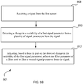
- An exemplary method for obtaining information for use with an orientation determination for a computing device may include receiving magnetometer data at a magnetic vector filter, wherein the magnetometer data may comprise sensor output from a magnetometer and receiving gyroscope data at the magnetic vector filter, wherein the gyroscope data may comprise sensor output from a gyroscope. Furthermore, the method may include determining a magnetic vector by using the magnetometer data and the gyroscope data in the magnetic vector filter.
- the magnetic vector filter may be capable of determining the magnetic vector independent of accelerometer data for use with the orientation determination.
- An exemplary method for obtaining information for use with an orientation determination for a computing device may also include receiving the accelerometer data at a gravity vector filter, wherein the accelerometer data comprises sensor output from an accelerometer and receiving the gyroscope data at the gravity vector filter. Furthermore, the method may include determining a gravity vector by using the accelerometer data and the gyroscope data in the gravity vector filter, wherein the gravity vector is used for determining the orientation of the computing device.
- the gravity vector filter and the magnetic vector filter use an adaptive filter, and at least one filter parameter of the adaptive filter is dynamically adjustable.
- the adaptive filter may be a Kalman filter.
- the at least one filter parameter associated with a gravity vector filter may comprise one or more of a signal noise, a measurement error, a sensor calibration error or a linear acceleration.
- the at least one filter parameter associated with the magnetic vector filter may comprise one or more of sensor calibration error or a magnetic transient field.
- the magnetic vector filter may be separate from the gravity vector filter.
- an expanded adaptive filter is implemented, wherein the expanded adaptive filter receives as inputs computed coordinates of the gravity vector for the computing device along with the gyroscope data and the accelerometer data.
- the method performed by components of the device further determines based on the magnetometer data and the gyroscope data, whether a detected change in a magnetic field in the magnetic vector filter is a magnetic anomaly. In one implementation, in response to determining that the gyroscope did not measure a change during a period of time in which the change in the magnetic field was detected, the method determines that the detected change in the magnetic field is the magnetic anomaly.
- the detected change in the magnetic field may be determined not to be the magnetic anomaly when the received sensor input from the gyroscope correlates to a detected change in the magnetic field, and the detected change in the magnetic field may be determined to be the magnetic anomaly when the received sensor input from the gyroscope does not correlate to the detected change in the magnetic field.
- the method in response to determining that the detected change in the magnetic field is the magnetic anomaly, disregards filter input received from the magnetometer corresponding to the detected change in the magnetic field.
- the method increases a window size associated with the magnetic vector filter.
- determining the detected change is a magnetic anomaly may comprise comparing the magnetometer data to a threshold, wherein the threshold may be based at least in part on the gyroscope data.
- An exemplary computing device for determining orientation may include a receiver coupled to a magnetic vector filter and configured to receive magnetometer data at a magnetic vector filter, wherein the magnetometer data may comprise sensor output from a magnetometer and the same or different receiver configured to receive gyroscope data at the magnetic vector filter, wherein the gyroscope data may comprise sensor output from a gyroscope.
- the components of the exemplary computing device such as the magnetic vector filter may determine a magnetic vector by using the magnetometer data and the gyroscope data in the magnetic vector filter.
- the magnetic vector filter may be capable of determining the magnetic vector independent of accelerometer data for use with the orientation determination.
- the exemplary computing device for determining orientation may also include a receiver coupled to a gravity vector filter for receiving the accelerometer data at a gravity vector filter, wherein the accelerometer data comprises sensor output from an accelerometer and the same or different receiver for receiving the gyroscope data at the gravity vector filter.
- the components of the exemplary computing device such as the gravity vector filter, may determine a gravity vector by using the accelerometer data and the gyroscope data in the gravity vector filter, wherein the gravity vector is used for determining the orientation of the computing device.
- the gravity vector filter and the magnetic vector filter use an adaptive filter, and at least one filter parameter of the adaptive filter is dynamically adjustable.
- the adaptive filter may be a Kalman filter.
- the at least one filter parameter associated with a gravity vector filter may comprise one or more of a signal noise, a measurement error, a sensor calibration error or a linear acceleration.
- the at least one filter parameter associated with the magnetic vector filter may comprise one or more of sensor calibration error or a magnetic transient field.
- the magnetic vector filter may be separate from the gravity vector filter.
- an expanded adaptive filter is implemented, wherein the expanded adaptive filter receives as inputs computed coordinates of the gravity vector for the computing device along with the gyroscope data and the accelerometer data.
- components of the device further determines, based on the magnetometer data and the gyroscope data, whether a detected change in a magnetic field in the magnetic vector filter is a magnetic anomaly. In one implementation, in response to determining that the gyroscope did not measure a change during a period of time in which the change in the magnetic field was detected, the computing device determines that the detected change in the magnetic field is the magnetic anomaly.
- the detected change in the magnetic field may be determined not to be the magnetic anomaly when the received sensor input from the gyroscope correlates to a detected change in the magnetic field, and the detected change in the magnetic field may be determined to be the magnetic anomaly when the received sensor input from the gyroscope does not correlate to the detected change in the magnetic field.
- components of the computing device in response to determining that the detected change in the magnetic field is the magnetic anomaly, disregards filter input received from the magnetometer corresponding to the detected change in the magnetic field.
- components of the computing device increases a window size associated with the magnetic vector filter.
- determining the detected change is a magnetic anomaly may comprise comparing the magnetometer data to a threshold, wherein the threshold may be based at least in part on the gyroscope data.
- An exemplary non-transitory computer readable storage medium may include instructions executable by a processor, the instructions comprising instructions to receive magnetometer data at a magnetic vector filter, wherein the magnetometer data comprises sensor output from a magnetometer, to receive gyroscope data at the magnetic vector filter, wherein the gyroscope data comprises sensor output from a gyroscope, and to determine a magnetic vector by using the magnetometer data and the gyroscope data in the magnetic vector filter, the magnetic vector filter being capable of determining the magnetic vector independent of accelerometer data for use with the orientation determination.
- the exemplary non-transitory computer readable storage medium may further include instructions executable by a processor, to determine based on the magnetometer data and the gyroscope data, whether a detected change in a magnetic field in the magnetic vector filter is a magnetic anomaly.
- the detected change in the magnetic field may be determined not to be the magnetic anomaly when the received sensor input from the gyroscope correlates to a detected change in the magnetic field; and the detected change in the magnetic field may be determined to be the magnetic anomaly when the received sensor input from the gyroscope does not correlate to the detected change in the magnetic field.
- the exemplary non-transitory computer readable storage medium may further include instructions executable by a processor to disregard filter input received from the magnetometer corresponding to the detected change in the magnetic field or/and increasing a window size associated with the magnetic vector filter, in response to determining that the detected change in the magnetic field is the magnetic anomaly.
- Another or same exemplary non-transitory computer readable storage medium described above may include instructions executable by a processor, the instructions comprising instructions to receive the accelerometer data at a gravity vector filter, wherein the accelerometer data comprises sensor output from an accelerometer, to receive the gyroscope data at the gravity vector filter; and to determine a gravity vector by using the accelerometer data and the gyroscope data in the gravity vector filter, wherein the gravity vector is used for determining the orientation of the computing device.
- the gravity vector filter and the magnetic vector filter use an adaptive filter, and at least one filter parameter of the adaptive filter is dynamically adjustable.
- An exemplary apparatus may include means for receiving magnetometer data at a magnetic vector filter, wherein the magnetometer data comprises sensor output from a magnetometer, means for receiving gyroscope data at the magnetic vector filter, wherein the gyroscope data comprises sensor output from a gyroscope, and means for determining a magnetic vector by using the magnetometer data and the gyroscope data in the magnetic vector filter, the magnetic vector filter being capable of determining the magnetic vector independent of accelerometer data for use with the orientation determination.
- the exemplary apparatus may further include means for determining based on the magnetometer data and the gyroscope data, whether a detected change in a magnetic field in the magnetic vector filter is a magnetic anomaly.
- the detected change in the magnetic field may be determined not to be the magnetic anomaly when the received sensor input from the gyroscope correlates to a detected change in the magnetic field; and the detected change in the magnetic field may be determined to be the magnetic anomaly when the received sensor input from the gyroscope does not correlate to the detected change in the magnetic field.
- the exemplary apparatus may further include means for disregarding filter input received from the magnetometer corresponding to the detected change in the magnetic field or/and a means for increasing a window size associated with the magnetic vector filter, in response to determining that the detected change in the magnetic field is the magnetic anomaly.
- Another or same exemplary apparatus described above may include means for receiving the accelerometer data at a gravity vector filter, wherein the accelerometer data comprises sensor output from an accelerometer, means for receiving the gyroscope data at the gravity vector filter; and means for determining a gravity vector by using the accelerometer data and the gyroscope data in the gravity vector filter, wherein the gravity vector is used for determining the orientation of the computing device.
- the gravity vector filter and the magnetic vector filter use an adaptive filter, and at least one filter parameter of the adaptive filter is dynamically adjustable.
- An embodiment described herein includes a device.
- the device comprises a gravity filter configured to filter inputs from an accelerometer and a gyroscope, and a magnetic filter configured to filter inputs from a magnetometer and a gyroscope.
- the gravity filter is separate from the magnetic filter.
- at least one of the gravity filter and the magnetic filter use an adaptive filter, and at least one filter parameter of the adaptive filter is dynamically adjustable.
- the gyroscope from which inputs are received by the gravity filter is the gyroscope from which inputs are received by the magnetic filter.
- the gravity filter comprises a gravity vector filter and/or the magnetic filter comprises a magnetic vector filter.
- An embodiment described herein includes a method for determining a magnetic anomaly.
- the method comprises receiving magnetometer data at a magnetic vector filter, receiving gyroscope data at the magnetic vector filter, and determining based on the magnetometer data and the gyroscope data, whether a detected change in a magnetic field in the magnetic vector filter comprises a magnetic anomaly.
- the magnetometer data comprises measurements or other information output from a magnetometer.
- the gyroscope data comprises measurements or other information output from a gyroscope.
- the method comprises determining that the detected change is a magnetic anomaly when the gyroscope did not measure a change during a period of time in which the change in the magnetic field was detected.
- the method comprises disregarding or mitigating filter input received from the magnetometer corresponding to the detected change in the magnetic field when the detected change is determined to be a magnetic anomaly. In some embodiments, the method comprises increasing a window size associated with an input from the magnetometer when the detected change is determined to be a magnetic anomaly.
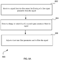
- An exemplary method for filtering data associated with a first sensor coupled to a computing device not being part of the claimed invention may include receiving a signal from the first sensor, detecting a change in a variability of a first signal parameter from a plurality of signal parameters from the signal, and adjusting, based at least in part on the detected change in the variability of the first signal parameter, at least one filter parameter of a filter used to filter a second signal parameter from the signal.
- the filter may be an adaptive filter and the at least one filter parameter of the adaptive filter may be dynamically adjustable.
- the adaptive filter is a Kalman filter.
- the at least one filter parameter of the filter may comprise a window size for the filter, wherein the window size for the filter is directly proportional to the variability of the first signal parameter.
- the at least one filter parameter may comprise a gain for the filter, wherein the gain for the filter is inversely proportional to the variability of the first signal parameter.
- the first sensor may be an accelerometer, the second signal parameter may be a gravity vector and the first signal parameter may be a signal parameter other than the gravity vector.
- the first signal parameter may be one or more of a signal noise, a measurement error, a sensor calibration error or a linear acceleration of the device.
- the first sensor may be a magnetometer, the second signal parameter may be a magnetic vector and the first signal parameter may be a signal parameter other than the magnetic vector.
- the first signal parameter may include one or more of a signal noise, a sensor calibration error or a magnetic transient field.
- detecting the change in the variability of the first signal parameter by the method comprises determining that the device has transitioned to a substantially stationary state.
- the method further comprises transitioning the first sensor to a low power state in response to determining, using a second sensor, that the device has transitioned to a substantially stationary state.
- the first sensor may be a gyroscope or/and a magnetometer and the second sensor may be an accelerometer.
- transitioning to the low power state may include switching off or duty cycling the first sensor.
- the method may further comprise transitioning the filter to a low power state in response to determining, using a second sensor, that the device has transitioned to a substantially stationary state.
- An exemplary computer device for filtering data associated with a first sensor not being part of the claimed invention may include a receiver configured to receive a signal from the first sensor, and a filter having at least one filter parameter used to filter a first signal parameter from the signal, the at least one filter parameter being adjustable based at least in part on a detected change in variability of a second signal parameter from a plurality of signal parameters from the signal.
- the filter may be an adaptive filter and the at least one filter parameter of the adaptive filter may be dynamically adjustable.
- the adaptive filter is a Kalman filter.
- the at least one filter parameter of the filter may comprise a window size for the filter, wherein the window size for the filter is directly proportional to the variability of the first signal parameter.
- the at least one filter parameter may comprise a gain for the filter, wherein the gain for the filter is inversely proportional to the variability of the first signal parameter.
- the first sensor may be an accelerometer, the second signal parameter may be a gravity vector and the first signal parameter may be a signal parameter other than the gravity vector.
- the first signal parameter may be one or more of a signal noise, a measurement error, a sensor calibration error or a linear acceleration of the device.
- the first sensor may be a magnetometer, the second signal parameter may be a magnetic vector and the first signal parameter may be a signal parameter other than the magnetic vector.
- the first signal parameter may include one or more of a signal noise, a sensor calibration error or a magnetic transient field.
- detecting the change in the variability of the first signal parameter by the computing device may include determining that the device has transitioned to a substantially stationary state.
- the computing device may further comprises transitioning the first sensor to a low power state in response to determining, using a second sensor, that the device has transitioned to a substantially stationary state.
- the first sensor may be a gyroscope or/and a magnetometer and the second sensor may be an accelerometer.
- transitioning to the low power state may include switching off or duty cycling the first sensor.
- the computing device may further comprise transitioning the filter to a low power state in response to determining, using a second sensor, that the device has transitioned to a substantially stationary state.
- non-transitory computer readable storage medium not being part of the claimed invention, wherein the non-transitory computer readable storage medium comprises instructions executable by processing logic, the instructions comprising instructions to receive a signal from the first sensor, detect a change in a variability of a first signal parameter from a plurality of signal parameters from the signal, and adjust, based at least in part on the detected change in the variability of the first signal parameter, at least one filter parameter of a filter used to filter a second signal parameter from the signal.
- the filter may be an adaptive filter and the at least one filter parameter of the adaptive filter may be dynamically adjustable.
- the at least one filter parameter of the filter may comprise a window size for the filter, wherein the window size for the filter may be directly proportional to the variability of the first signal parameter.
- the at least one filter parameter may comprise a gain for the filter, wherein the gain for the filter is inversely proportional to the variability of the first signal parameter.
- the exemplary non-transitory computer readable storage medium may further comprise instructions to transition the filter to a low power state in response to determining, using a second sensor, that the device has transitioned to a substantially stationary state.
- An exemplary apparatus may include means for receiving a signal from the first sensor, means for detecting a change in a variability of a first signal parameter from a plurality of signal parameters from the signal, and means for adjusting, based at least in part on the detected change in the variability of the first signal parameter, at least one filter parameter of a filter used to filter a second signal parameter from the signal.
- the filter may be an adaptive filter and the at least one filter parameter of the adaptive filter may be dynamically adjustable.
- the at least one filter parameter of the filter may comprise a window size for the filter, wherein the window size for the filter is directly proportional to the variability of the first signal parameter.
- the at least one filter parameter may comprise a gain for the filter, wherein the gain for the filter is inversely proportional to the variability of the first signal parameter.
- the exemplary apparatus may further comprise means for transitioning the filter to a low power state in response to determining, using a second sensor, that the device has transitioned to a substantially stationary state.
- An embodiment described herein includes a device.
- the device comprises a gravity filter configured to filter inputs from an accelerometer and a gyroscope, and a magnetic filter configured to filter inputs from a magnetometer and a gyroscope.
- at least one of the gravity filter and the magnetic filter use an adaptive filter, and at least one filter parameter of the adaptive filter is dynamically adjustable.
- the gyroscope from which inputs are received by the gravity filter is the gyroscope from which inputs are received by the magnetic filter.
- the gravity filter comprises a gravity vector filter and the magnetic filter comprises a magnetic vector filter.
- An embodiment described herein includes a method for determining a magnetic anomaly.
- the method comprises receiving magnetometer data at a magnetic vector filter, receiving gyroscope data at the magnetic vector filter, and determining based on the magnetometer data and the gyroscope data, whether a detected change in a magnetic field in the magnetic vector filter comprises a magnetic anomaly.
- the magnetometer data comprises measurements or other information output from a magnetometer.
- the gyroscope data comprises measurements or other information output from a gyroscope.
- the method comprises determining that the detected change is a magnetic anomaly when the gyroscope did not measure a change during a period of time in which the change in the magnetic field was detected.
- the method comprises disregarding or mitigating filter input received from the magnetometer corresponding to the detected change in the magnetic field when the detected change is determined to be a magnetic anomaly. In some embodiments, increasing a window size associated with an input from the magnetometer when the detected change is determined to be a magnetic anomaly.
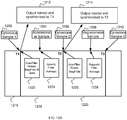
- An exemplary method for synchronizing information at a computing device not being part of the claimed invention may include determining a common sensor input from a plurality of sensor inputs; and synchronizing output for generating the orientation data with the common sensor input, wherein the orientation data is generated using the plurality of sensor inputs.
- synchronizing the output for generating the orientation data with the common sensor input comprises synchronizing one or more remaining sensor inputs to the common sensor input by averaging the one or more remaining sensor inputs until arrival of the common sensor input, wherein the one or more remaining sensor inputs are sensor inputs from the plurality of sensor inputs other than the common sensor input.
- synchronizing the output for generating the orientation data with the common sensor input comprises propagating at least one sensor input of the plurality of sensor inputs to the common sensor input, and wherein the method further comprises generating the orientation data using a plurality of filters based on the common sensor input and the propagated one or more sensor inputs.
- the common sensor input may comprise an input from a gyroscope and one or more remaining sensor inputs of the plurality of sensor inputs other than the common sensor input may comprise inputs from an accelerometer and/or a magnetometer.
- the exemplary method not being part of the claimed invention may also comprise filtering the common sensor input and the one or more remaining sensor inputs using a plurality of filters, the plurality of filters comprising a gravity vector filter for determining a gravity vector associated with the computing device using data from the accelerometer and the gyroscope, and a magnetic vector filter for determining a magnetic vector associated with the computing device using data from the magnetometer and the gyroscope.
- the method may detect an operating system framework on the computing device that accepts the orientation data as a unified orientation data point in time, wherein the synchronizing is performed in response to the detecting of the operating system framework.
- the exemplary method not being part of the claimed invention may further comprise determining components of the orientation data represented in a quaternion system, determining that an angle component from the components of the orientation data represented in the quaternion system is negative, and in response to determining that the angle component is negative, adjusting the components of the orientation data represented using the quaternion system so that the angle component is positive.
- the method may further include detecting an operating system framework on the computing device that passes only three components of the quaternion system to an application layer, wherein the adjusting the components is performed in response to the detecting the operating system framework.
- the exemplary method not being part of the claimed invention may further comprise determining linear acceleration for the orientation data, wherein determining the linear acceleration comprises, determining a measured acceleration associated with the computing device, determining a non-normalized gravity vector associated with the computing device; and determining the linear acceleration of the computing device by removing a non-normalized gravity component of a gravity vector from the measured acceleration of the computing device.
- An exemplary computing device not being part of the claimed invention for synchronizing information may include processing logic to determine a common sensor input from a plurality of sensor inputs; and to synchronize output for generating the orientation data with the common sensor input, wherein the orientation data is generated using the plurality of sensor inputs.
- synchronizing the output for generating the orientation data with the common sensor input comprises synchronizing one or more remaining sensor inputs to the common sensor input by averaging the one or more remaining sensor inputs until arrival of the common sensor input, wherein the one or more remaining sensor inputs are sensor inputs from the plurality of sensor inputs other than the common sensor input.
- synchronizing the output for generating the orientation data with the common sensor input comprises propagating at least one sensor input of the plurality of sensor inputs to the common sensor input, and wherein the exemplary computing device further comprises generating the orientation data using a plurality of filters based on the common sensor input and the propagated one or more sensor inputs.
- the common sensor input may comprise an input from a gyroscope and one or more remaining sensor inputs of the plurality of sensor inputs other than the common sensor input may comprise inputs from an accelerometer and/or a magnetometer.
- the exemplary computing device may also comprise processing logic configured to filter the common sensor input and the one or more remaining sensor inputs using a plurality of filters, the plurality of filters comprising a gravity vector filter for determining a gravity vector associated with the computing device using data from the accelerometer and the gyroscope, and a magnetic vector filter for determining a magnetic vector associated with the computing device using data from the magnetometer and the gyroscope.
- the processing logic may be configured to detect an operating system framework on the computing device that accepts the orientation data as a unified orientation data point in time, wherein the synchronizing is performed in response to the detecting of the operating system framework.
- the exemplary computing device not being part of the claimed invention may further comprise processing logic configured to determine components of the orientation data represented in a quaternion system, to determine that an angle component from the components of the orientation data represented in the quaternion system is negative, and in response to determining that the angle component is negative, to adjust the components of the orientation data represented using the quaternion system so that the angle component is positive.
- the computing device may further include detecting an operating system framework on the computing device that passes only three components of the quaternion system to an application layer, wherein the adjusting the components is performed in response to the detecting the operating system framework.
- the exemplary computing device may further comprise processing logic configured to determine linear acceleration for the orientation data, wherein determining the linear acceleration comprises, determining a measured acceleration associated with the computing device, determining a non-normalized gravity vector associated with the computing device; and determining the linear acceleration of the computing device by removing a non-normalized gravity component of a gravity vector from the measured acceleration of the computing device.
- An exemplary non-transitory computer readable storage medium not being part of the claimed invention comprises instructions executable by processing logic, the instructions comprising instructions to determine a common sensor input from a plurality of sensor inputs; and synchronize output for generating the orientation data with the common sensor input, wherein the orientation data is generated using the plurality of sensor inputs.
- synchronizing the output for generating the orientation data with the common sensor input comprises synchronizing one or more remaining sensor inputs to the common sensor input by averaging the one or more remaining sensor inputs until arrival of the common sensor input, wherein the one or more remaining sensor inputs are sensor inputs from the plurality of sensor inputs other than the common sensor input.
- synchronizing the output for generating the orientation data with the common sensor input comprises propagating at least one sensor input of the plurality of sensor inputs to the common sensor input, and wherein the exemplary non-transitory computer readable storage medium may also comprise instructions to generate the orientation data using a plurality of filters based on the common sensor input and the propagated one or more sensor inputs.
- the common sensor input may comprise an input from a gyroscope and one or more remaining sensor inputs of the plurality of sensor inputs other than the common sensor input may comprise inputs from an accelerometer and/or a magnetometer.
- the exemplary non-transitory computer readable storage medium not being part of the claimed invention may also comprise instructions to filter the common sensor input and the one or more remaining sensor inputs using a plurality of filters, the plurality of filters comprising a gravity vector filter for determining a gravity vector associated with the computing device using data from the accelerometer and the gyroscope, and a magnetic vector filter for determining a magnetic vector associated with the computing device using data from the magnetometer and the gyroscope.
- the exemplary non-transitory computer readable storage medium may also comprise instructions to detect an operating system framework on the computing device that accepts the orientation data as a unified orientation data point in time, wherein the synchronizing is performed in response to the detecting of the operating system framework.
- the exemplary non-transitory computer readable storage medium not being part of the claimed invention may also comprise instructions to determine components of the orientation data represented in a quaternion system, determine that an angle component from the components of the orientation data represented in the quaternion system is negative, and in response to determining that the angle component is negative, to adjust the components of the orientation data represented using the quaternion system so that the angle component is positive.
- the exemplary non-transitory computer readable storage medium may also comprise instructions to detect an operating system framework on the computing device that passes only three components of the quaternion system to an application layer, wherein the adjusting the components is performed in response to the detecting the operating system framework.
- the exemplary non-transitory computer readable storage medium may also comprise instructions to determine linear acceleration for the orientation data, wherein determining the linear acceleration comprises, determining a measured acceleration associated with the computing device, determining a non-normalized gravity vector associated with the computing device; and determining the linear acceleration of the computing device by removing a non-normalized gravity component of a gravity vector from the measured acceleration of the computing device.
- An exemplary apparatus not being part of the claimed invention may include means for determining a common sensor input from a plurality of sensor inputs; and means for synchronizing output for generating the orientation data with the common sensor input, wherein the orientation data is generated using the plurality of sensor inputs.
- synchronizing the output for generating the orientation data with the common sensor input comprises means for synchronizing one or more remaining sensor inputs to the common sensor input by averaging the one or more remaining sensor inputs until arrival of the common sensor input, wherein the one or more remaining sensor inputs are sensor inputs from the plurality of sensor inputs other than the common sensor input.
- synchronizing the output for generating the orientation data with the common sensor input comprises means for propagating at least one sensor input of the plurality of sensor inputs to the common sensor input, and wherein the apparatus further comprises means for generating the orientation data using a plurality of filters based on the common sensor input and the propagated one or more sensor inputs.
- the common sensor input may comprise an input from a gyroscope and one or more remaining sensor inputs of the plurality of sensor inputs other than the common sensor input may comprise inputs from an accelerometer and/or a magnetometer.
- the exemplary apparatus not being part of the claimed invention may also comprise means for filtering the common sensor input and the one or more remaining sensor inputs using a plurality of filters, the plurality of filters comprising a gravity vector filter for determining a gravity vector associated with the computing device using data from the accelerometer and the gyroscope, and a magnetic vector filter for determining a magnetic vector associated with the computing device using data from the magnetometer and the gyroscope.
- the apparatus may comprise a means for detecting an operating system framework on the computing device that accepts the orientation data as a unified orientation data point in time, wherein the synchronizing is performed in response to the detecting of the operating system framework.
- the exemplary apparatus may further comprise means for determining components of the orientation data represented in a quaternion system, means for determining that an angle component from the components of the orientation data represented in the quaternion system is negative, and in response to determining that the angle component is negative, means for adjusting the components of the orientation data represented using the quaternion system so that the angle component is positive.
- the apparatus may further include means for detecting an operating system framework on the computing device that passes only three components of the quaternion system to an application layer, wherein the adjusting the components is performed in response to the detecting the operating system framework.
- the exemplary apparatus may further comprise means for determining linear acceleration for the orientation data, wherein means for determining the linear acceleration comprises, means for determining a measured acceleration associated with the computing device, means for determining a non-normalized gravity vector associated with the computing device; and means for determining the linear acceleration of the computing device by removing a non-normalized gravity component of a gravity vector from the measured acceleration of the computing device.
- An embodiment described herein includes a device.
- the device comprises a gravity filter configured to filter inputs from an accelerometer and a gyroscope, and a magnetic filter configured to filter inputs from a magnetometer and a gyroscope.
- at least one of the gravity filter and the magnetic filter use an adaptive filter, and at least one filter parameter of the adaptive filter is dynamically adjustable.
- the gyroscope from which inputs are received by the gravity filter is the gyroscope from which inputs are received by the magnetic filter.
- the gravity filter comprises a gravity vector filter and/or the magnetic filter comprises a magnetic vector filter.
- An embodiment described herein includes a method for determining a magnetic anomaly.
- the method comprises receiving magnetometer data at a magnetic vector filter, receiving gyroscope data at the magnetic vector filter, and determining based on the magnetometer data and the gyroscope data, whether a detected change in a magnetic field in the magnetic vector filter comprises a magnetic anomaly.
- the magnetometer data comprises measurements or other information output from a magnetometer.
- the gyroscope data comprises measurements or other information output from a gyroscope.
- the method comprises determining that the detected change is a magnetic anomaly when the gyroscope did not measure a change during a period of time in which the change in the magnetic field was detected.
- the method comprises disregarding or mitigating filter input received from the magnetometer corresponding to the detected change in the magnetic field when the detected change is determined to be a magnetic anomaly. In some embodiments, increasing a window size associated with an input from the magnetometer when the detected change is determined to be a magnetic anomaly.
- Techniques are provided for a power efficient system for determining motion and/or orientation of a device 1600, for example by determining the gravity vector, magnetic vector, linear acceleration and/or rotation vector in the device 1600 based on sensors 1650.
- sensors used are accelerometer 1655, magnetometer 1665 and gyroscope 1660.
- techniques are provided for potentially speeding up the determination of the gravity vector, rotational vector and linear acceleration while saving power, increasing the accuracy and reformatting the output for popular operating system frameworks, such as Google Android that have specific requirements for the presentation format for the gravity vector, linear acceleration and quaternion (rotation) vector.
- orientation data such as the quaternion (rotation) vector
- gravity vector the angles calculated using the gravity vector may be used to describe the orientation relative to the earth by describing the orientation relative to the horizontal plane or the inclination to this plane.
- the magnetic vector can be used to derive orientation data using the horizontal component of the Earth's magnetic field and the local declination.
- orientation data such as the gravity vector lends itself to the orientation with respect to the horizontal plane using pitch and roll angles.
- the Gravity vector components can be determined from gyroscope 1660 and accelerometer 1655 measurements, for instance by gyro-aided filtering of acceleration. Earth's magnetic field measurements are also available, allowing for determination of the third Euler angle Yaw (referred to as Azimuth angle in Google® Android terminology).
- the 3D orientation may also be represented in the form of either 9-elements rotation matrix or its 4-elements compression to quaternion or rotation vector (RV).
- One way of determining orientation may be by using gyroscope 1660, accelerometer 1655 and magnetometer 1665 output in Kalman filter equations. Examples may also use an alternative implementation for determining the Rotational Vector from the gravity vector and the (gyroscope-aided) filtered magnetic vector.
- the two vectors' cross-product may yield a horizontal vector pointing East and the cross product with the gravity vector may in turn yield a horizontal vector pointing North.
- Each of these 3 vectors: vertical Gravity, horizontal east, and horizontal north may constitute one column of the 3 ⁇ 3 rotation matrix that can be output as is or compressed to Rotational Vector.
- Embodiments of the invention include independent filters for accelerometer 1655 (gravity vector filter) and magnetometer 1665 (magnetic vector filter) instead of using a single filter.
- the embodiments of the invention can use adaptive filters that adjust the gain and window allowing for faster and more accurate results from the sensors.
- magnetometer 1665 and some filters can be transitioned to a lower power state. Examples not being part of the claimed invention also include techniques for increasing accuracy for determining linear acceleration by using a non-normalized gravity vector and providing a mechanism for the application layer to derive the fourth component of a quaternion system.
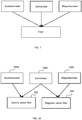
- FIG. 1 is a block diagram that illustrates a system for filtering the output of an accelerometer 1655, gyroscope 1660 and a magnetometer 1665 using a single filter.
- these filter systems may be difficult to calibrate with accuracy since changing the different calibration parameters have different effects for filtering different sensors. For instance, an accelerometer (for finding the gravity vector) and a magnetometer (for finding the magnetic vector) may associate different environmental factors as noise. Therefore, during any given period of time noise for an accelerometer may be different than noise for a magnetometer. In such a system, a large static time constant for the window used for the filter may be required to properly remove error from both the accelerometer and magnetometer output.
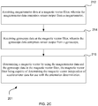
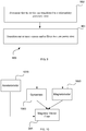
- FIG. 2A is a block diagram that illustrates a system for filtering the output of an accelerometer 1655 and a magnetometer 1665 along with a gyroscope 1660 using separate filters.
- the accelerometer data and the gyroscope data are processed together at a gravity vector filter 202 for determining the gravity vector.
- a processor such as the processor 1610 illustrated in FIG. 16 or a controller or a component of gravity vector filter 202 may be used in processing the sensor data.
- the magnetometer data and the gyroscope data are processed together at a magnetic vector filter 204 to determine the magnetic vector.
- a processor such as the processor 1610 illustrated in FIG. 16 or a controller or a component of magnetic vector filter 204 may be used in processing the sensor data.
- an adaptive filter is used that allows dynamically adjusting of one or more parameters of the adaptive filter using the processor 1610, a controller or components of the filter.
- the adaptive filter may be a Kalman filter.
- samples or output data from the sensors 1650 are accumulated over a time period dictated by a time constant for the filter and filtered through a gravity vector filter 202 to derive the gravity vector.
- Filtering data through a filter may include processing the data at a processor 1610, a controller, application specific integrated circuit (ASIC) or any other digital or analog logic on the device 1600.
- the gravity vector filter 202 may be implemented in hardware or executing software on a processor 1610, and/or temporarily stored in working memory 1635.
- Time constant may also be referred as a window size for the filter, and may be used interchangeably throughout the specification.
- One or more signal parameters from the accelerometer 1655 or/and the gyroscope 1660 may act as noise and may have a detrimental effect in determining the gravity vector.
- noise associated with the gravity vector filter 202 may be used broadly to include any signal parameters besides the gravity vector itself that may be detrimental in determining the gravity vector.
- these signal parameters may include but are not limited to actual measurement noise, sensor calibration errors and estimated level of linear acceleration. Noise may be contributed from the errors in calibration of the sensors or noise in the environment.
- Linear acceleration may also be referred to as translational acceleration, and may be used interchangeably, throughout the specification.
- An accelerometer 1655 may work on the principal of measuring the force in the various directions. When the device 1600 and consequentially the coupled accelerometer 1655 are in motion, the force from the gravity field and the acceleration may be indiscernible and the accelerometer 1655 may not be able to tell one from the other.
- the purpose of the gravity vector filter 202 may be to find the gravity vector, as opposed to linear acceleration for example, and therefore linear acceleration may be noise since it may detract from obtaining the true gravity vector.
- acceleration of the device 1600 can be treated as noise.
- the device 1600 when the device 1600 is stationary, the device 1600 experiences less noise and the gain of the gravity vector filter 202 can be increased to reduce the settle time for the gravity vector filter 202.
- the device 1600 When the device 1600 is in motion there is greater successive filter error and samples over a longer period of time may be used to derive the gravity vector.
- the noise significantly reduces when the device 1600 is stationary and gravity vector filtering with shorter time constant is possible.
- a device such as the device 1600 described in FIG 1600, may be stationary for a few brief moments due to the user sitting down with the device 1600 in his/her pocket or keeping the device 1600 on a table for a few brief moments.
- the stationary position of the device 1600 can be discerned from the output of the accelerometer 1655, the gyroscope 1660, the magnetometer 1665 or using any other sensor output.
- the device 1600 When the device 1600 is in a stationary position there is less noise, and samples over a shorter period of time (i.e. shorter time constant) with higher gain are sufficient in deriving the gravity vector from the gravity vector filter 202. In other words, the output of the filter settles much faster since the error is written off faster.
- calculations of the gravity vector performed when the device 1600 is stationary may largely be attributed to the relative dynamics of the device 1600, in contrast to the noise or sensor error typically observed during an extended time period and/or while the device 1600 is in motion.
- a processor such as the processor 1610 illustrated in FIG. 16 or a controller or component of the gravity vector filter 202 may adjust an operating parameter(s) of the filter, for example a time constant, and/or gain of the filter. The adjustment may be performed in response to detecting that the device 1600 is stationary, detecting a reduction in noise, or detecting another change in a status, signal, or variability of a signal of the device 1600 or sensors 1650 thereof.
- the adjustment to the operating parameter for the gravity vector filter 202 may be determined in any number of ways. In one embodiment, the adjustment is roughly proportional to a level of motion of the device 1600. Thus, the time constant may be continually or constantly adjusted by the processor 1610 or a controller. In another embodiment, the adjustment is determined by looking up a motion state of the device 1600 in a table, by the processor 1610 or a controller, and determining a corresponding adjustment based on the lookup state. For example, a first time constant may be used when the device 1600 is in motion, and a second time constant may be used when the device 1600 is substantially stationary.
- the first time constant when the device 1600 is in motion may be 5 seconds
- the second time constant when the device 1600 is in substantially stationary position may be 1.4 seconds
- a third time constant may be used when the device 1600 is absolutely stationary.
- the third constant may be 0.6 seconds.
- Such an exemplary table may be dynamically or statically generated and stored in the Storage device 1625 and temporarily loaded in the working memory 1635 for access.
- FIG. 2B is a simplified flow diagram illustrating a non-limiting example for determining the gravity vector.
- the process 200 may be performed by a processor 1610 or processing logic that comprises hardware (circuitry, dedicated logic, etc.), software (such as is run on a general purpose computing system or a dedicated machine), firmware (embedded software), or any combination thereof.
- the process 200 is performed by one or more computer systems 1600 as described in FIG. 16 .
- the sensors 1650 acquire the sensor input for further processing by filtering and processing by components of the device described in FIG. 16 .
- accelerometer data may be received at a gravity vector filter 202, wherein the accelerometer data comprises sensor output from an accelerometer 1655.
- block 206 may be performed by components of the device 1600, such as a receiver or other interface (not shown) coupled to the gravity vector filter 202 for receiving sensor data.
- gyroscope data may be received at the gravity vector filter 202, wherein the gyroscope data comprises sensor output from a gyroscope 1660.
- block 208 may be performed by components of the device 1600, such as a receiver or other interface (not shown) coupled to the gravity vector filter 202.
- components of the device such as the gravity vector filter 202 may determine the gravity vector by using the accelerometer data and the gyroscope data in the gravity vector filter, wherein the gravity vector may be used for determining the orientation of the computing device.
- the gravity vector filter 202 may be capable of determining the gravity vector independent of magnetometer data for use with the orientation determination.
- FIG. 2B provides a particular method of switching between modes of operation. Other sequences of steps may also be performed accordingly in alternative examples. For example, examples may perform the steps outlined above in a different order. To illustrate, a user may choose to change from the third mode of operation to the first mode of operation, the fourth mode to the second mode, or any combination there between.
- the individual steps illustrated in FIG. 2B may include multiple sub-steps that may be performed in various sequences as appropriate to the individual step. Furthermore, additional steps may be added or removed depending on the particular applications.
- One of ordinary skill in the art would recognize and appreciate many variations, modifications, and alternatives of the process.
- one or more signal parameters from the magnetometer 1665 or/and the gyroscope 1660 may act as noise in determining the magnetic vector.
- the signal parameters that are detrimental in determining the magnetic vector may be different than the signal parameters detrimental in determining the gravity vector.
- noise associated with the magnetic vector filter 204 may be used broadly to include any signal parameters besides the magnetic vector itself that may be detrimental in determining the magnetic vector. In some instances, these signal parameters, may include but are not limited to the sensor calibration errors and an estimated magnetic transient field (i.e. transient anomalies in the magnetic field).
- the magnetic vector filter 204 attempts to filter out these errors and anomalies, wherein the filter may be implemented in hardware or executing software on a processor 1610, and/or temporarily stored in working memory 1635.
- the motion of the device 1600 may contribute to the noise.
- the magnetometer 1665 may not be affected by motion. Instead, the magnetometer 1665 readings may be affected by the magnetic anomalies and magnetic transient fields. Therefore, if no magnetic anomalies are detected, than the gain can be increased and the time constant for the magnetometer 1665 can be reduced. Higher gain with lower noise results in error accumulated in the device's magnetic environment to be read off faster.
- the time constant can be dynamically reduced during the time between the driving by of the trucks.
- the presence of transient magnetic filed may be determined by checking measured and filtered magnetic vector parameters such as magnitude and inclination from the horizon and stability (variance) over time.
- a processor such as the processor 1610 illustrated in FIG. 16 or a controller or component of the magnetic vector filter 204 may adjust an operating parameter(s) of the filter, for example, a time constant, and/or gain of the filter.
- the above parameters may be compared against standard earth magnetic field model parameters for current user location. The user location needs to be known with an accuracy of 10-20 miles and can be obtained using GNSS, cell ID or manual position entry.
- the gyroscope 1660 may make the fusion sensors output smoother and accurate; however, if the gyroscope 1660 calibration has errors then the orientation error contribution from the gyroscope 1660 could be estimated approximately by multiplying the gyroscope 1660 offset by (time) constant.
- the error measured using the gyroscope 1660 may accumulate and the gyroscope 1660 may pull the filter sideways over a larger window of time. Therefore, a shorter time constant may lead to a smaller error contribution from the gyroscope 1660.
- a long time constant may be used, however, when there is significant noise for accelerometer 1655 and/or magnetometer 1665 reading.
- the gravity vector filter 202 may use the readings from the accelerometer 1655 and the gyroscope 1660, whereas the magnetic vector filter 204 may use the readings from the magnetometer 1665 and the gyroscope 1660.
- Using a smaller time constant for the gravity vector filter 202 and the magnetic vector filter 204 may reduce the error introduced by the gyroscope 1660 by a factor of the time constant.
- Creating and/or implementing independent filters maybe especially beneficial since the environmental or other source of these various signal parameters that are detrimental in deriving the gravity vector using the accelerometer 1655 and the magnetic vector using the magnetometer 1665 may be different.
- the gravity vector filter 202 and the magnetic vector filter 204 can dynamically use different and shorter time constants associated with the filter depending on the detrimental signal parameter or noise detected from the environment using the sensors. For instance, a stationary device 1600 may have very little associated noise or detrimental signal parameters for calculating the gravity vector and therefore a smaller time constant may be used.
- the window size for the gravity vector filter 202 may be adjusted independent of the amount of transient magnetic field in the environment.
- the gain or in other words, the frequency of measurements that are allowed to pass through the filter or that are operated on by the filter may be increased during times of low detractive signal parameters for the gravity vector filter 202 and the magnetic vector filter 204, independent of each other.
- the accelerometer 1655 may still be used as an input to the magnetic vector filter 204.
- the accelerometer data may aid the magnetic filter by providing motion information to the magnetic vector filter 204 for the purpose of saving power or more efficiently calculating the magnetic vector.
- the accelerometer data from the accelerometer 1655 may also aid power saving techniques for the gyroscope 1660 and the magnetometer 1665, as further discussed in FIGS. 9 and 10 .
- FIG. 2C is a simplified flow diagram illustrating a non-limiting example for determining the magnetic vector.
- the process 201 may be performed by a processor 1610 or processing logic that comprises hardware (circuitry, dedicated logic, etc.), software (such as is run on a general purpose computing system or a dedicated machine), firmware (embedded software), or any combination thereof.
- the process 201 is performed by one or more computer systems 1600 as described in FIG. 16 .
- the sensors 1650 acquire the sensor input for further processing by filtering and processing by components of the device described in FIG. 16 .
- At magnetometer data may be received at the magnetic vector filter 204, wherein the magnetometer data comprises sensor output from a magnetometer 1665.
- block 212 may be performed by components of the device 1600, such as a receiver or other interface (not shown) coupled to the magnetic vector filter 204 and configured for receiving sensor data.
- At gyroscope data may be received at the magnetic vector filter 204, wherein the gyroscope data comprises sensor output from a gyroscope 1660.
- block 214 may be performed by components of the device 1600, such as a receiver or other interface (not shown) coupled to the magnetic vector filter 204.
- components of the device such as the magnetic vector filter 204 may determine the magnetic vector by using the magnetic vector data and the gyroscope data in the magnetic vector filter, wherein the magnetic vector may be used for determining the orientation of the computing device.
- the magnetic vector filter 204 may be capable of determining the magnetic vector independent of accelerometer data for use with the orientation determination.
- FIG. 2C provides a particular method of switching between modes of operation. Other sequences of steps may also be performed accordingly in alternative examples. For example, alternative examples may perform the steps outlined above in a different order. To illustrate, a user may choose to change from the third mode of operation to the first mode of operation, the fourth mode to the second mode, or any combination there between.
- the individual steps illustrated in FIG. 2C may include multiple sub-steps that may be performed in various sequences as appropriate to the individual step. Furthermore, additional steps may be added or removed depending on the particular applications.
- One of ordinary skill in the art would recognize and appreciate many variations, modifications, and alternatives of the process.
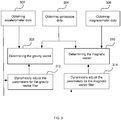
- FIG. 3 is a simplified flow diagram illustrating a non-limiting example for acquiring improved orientation data.
- the process 300 may be performed by a processor 1610 or processing logic that comprises hardware (circuitry, dedicated logic, etc.), software (such as is run on a general purpose computing system or a dedicated machine), firmware (embedded software), or any combination thereof.
- the process 300 is performed by one or more computer systems 1600 as described in FIG. 16 .
- the sensors 1650 acquire the sensor input for further processing by filtering and processing by components of the device described in FIG. 16 .
- the accelerometer 1655 and other modules coupled to the computing device 1600 obtain accelerometer data.
- the gyroscope 1660 coupled to the computing device 1600 obtains the gyroscope data and at block 306, the magnetometer 1665 obtains magnetometer data.
- the gyroscope 1660 and other modules coupled to the computing device 1600 obtain the gyroscope data.
- Other sensors 1650, not shown, may also be used in determining orientation of the device.
- the gravity vector filter 202 determines the gravity vector, using at least the accelerometer data and the gyroscope data, wherein the gravity vector is used for determining the orientation of the device 1600.
- the gravity vector filter 202 may use an adaptive filter, and may be implemented in software, firmware or hardware, using components of the device 1600, discussed in FIG. 16 .
- at least one filter parameter of the adaptive filter may be dynamically adjusted, by a processor 1610 or a controller, using the signal parameters from the one or more sensors.
- the accelerometer data is used in determining the at least one filter parameter for the gravity vector filter 202.
- some embodiments may also use the gyroscope data, magnetometer data and/or any other sensor data available in adjusting the parameters for the gravity vector filter 202.
- the filter parameter for the gravity vector filter 202 may be adjusted in response to detecting a change or variability in the signal parameters other than the gravity vector, such as noise, that are detrimental in determining the gravity vector.
- the magnetic vector filter 204 helps determine the magnetic vector, using at least the magnetometer data and the gyroscope data, wherein the magnetic vector is used for determining the orientation of the device 1600.
- the gyroscope -aided magnetic vector filter 204 also allows for a method for performing magnetic anomaly rejection.
- the magnetic vector filter 204 may use an adaptive filter and may be implemented in software, firmware or hardware, using components of the device 1600, discussed in FIG. 16 .
- at least one filter parameter of the adaptive filter may be dynamically adjusted, by the processor 1610 or a controller, using the signal parameters from the one or more sensors. In FIG.
- the accelerometer data is used in determining the at least one filter parameter for the gravity vector filter 202.
- some embodiments may also use the gyroscope data, magnetometer data and/or any other sensor data available in adjusting the parameters for the magnetic vector filter 204.
- the filter parameter for the magnetic vector filter 204 may be adjusted in response to detecting a change or variability in the signal parameters other than the gravity vector, such as noise, that are detrimental in determining the gravity vector.
- the adaptive filter associated with the gravity vector filter 202 or the magnetic vector filter 204 may use a Kalman filter to allow for adjusting of the parameters.
- the adaptive parameters of the adaptive filter may include, but are not limited to the time constant and the gain of the adoptive filter.
- separating out the determination of the gravity vector and the magnetic vector may be advantageous, since the signal parameters that are detrimental in determining the respective vectors, such as noise, associated with the gravity vector and the magnetic vector are different.
- the filter parameters for the gravity vector filter 202 and the magnetic vector filter 204 may be adjusted independently, by the processor 1610 or a controller coupled to the device 1600. Independently adjusting the filter parameters allows for finer granularity of changes in the filter parameters. For instance, the time constant for the respective filter may be adjusted specifically based on if the change in signal parameter was detrimental to the gravity vector filter 202 or magnetic vector filter 204.
- FIG. 3 provides a particular method of switching between modes of operation. Other sequences of steps may also be performed accordingly in alternative examples. For example, alternative examples may perform the steps outlined above in a different order. To illustrate, a user may choose to change from the third mode of operation to the first mode of operation, the fourth mode to the second mode, or any combination there between.
- the individual steps illustrated in FIG. 3 may include multiple sub-steps that may be performed in various sequences as appropriate to the individual step. Furthermore, additional steps may be added or removed depending on the particular applications.
- One of ordinary skill in the art would recognize and appreciate many variations, modifications, and alternatives of the process.
- the magnetic vector filter 204 may receive magnetometer data and gyroscope data for determining the magnetic vector. Data from the gyroscope 1660 may aid the magnetic vector filter in determining and rejecting anomalies in the data received from the magnetometer, as illustrated in FIGS. 4 and 5 and further discussed in FIG. 6
- FIGS. 4 and 5 illustrate example graphs in which data received from at least one magnetometer 1665 is compared with data received from at least one gyroscope 1660 according to one or more illustrative aspects of the disclosure.
- FIG. 4 illustrates an example graph 400 in which line 405 may represent the amplitude of magnetic field measurements (e.g., captured by magnetometer 1665) over a period of time, and further in which line 410 may represent the amplitude of gyroscopic motion measurements (e.g., captured by gyroscope 1660) over the same period of time.
- fluctuations in the magnetic field measurements generally correlate with fluctuations in the gyroscopic motion measurements (e.g., as represented by changes in line 410). Because the fluctuations in the magnetic field measurements correlate with the fluctuations in the gyroscopic motion measurements, it may be determined, based on the gyroscope data, that the magnetic field data does not contain anomalies, because, for instance, it is expected that when computing device 1600 experiences motion, there will be changes in both the gyroscopic motion measurements for the device 1600 (e.g., because the motion may cause changes in the device's 1600 orientation) and the magnetic field measurements for the device 1600 (e.g., because the motion may subject the device 1600 to slightly different gravitational forces, which may, for instance, be associated with changes in the device's 1600 bearing). In one embodiment, the determination is performed by the processor 1610, and may be based on instructions stored and executed from memory 1635.
- line 505 may represent the amplitude of magnetic field measurements (e.g., captured by magnetometer 1665) over a period of time
- line 510 may represent the amplitude of gyroscopic motion measurements (e.g., captured by gyroscope 1660) over the same period of time.
- fluctuations in the magnetic field measurements e.g., as represented by changes in line 505
- fluctuations in the gyroscopic motion measurements might not correlate with fluctuations in the gyroscopic motion measurements (e.g., as represented by changes in line 510).
- the spike in line 505 which may represent a sudden change in magnetic field measurements captured by magnetometer 1665, does not correlate with a corresponding change in line 510, which represents the gyroscopic motion measurements. Accordingly, the sudden change in magnetic field measurements may be determined to be an anomaly, for instance, using one or more of the methods and/or method steps as further described below. In one embodiment, the determination is performed by the processor 1610, and may be made using instructions stored and executed from memory 1635.
- FIG. 6 illustrates a simplified flow diagram illustrating a non-limiting method of performing gyroscope-aided magnetic anomaly rejection according to one or more illustrative aspects of the disclosure.
- any and/or all of the methods and/or methods steps described herein may be implemented by and/or in a computing device 1600, such as computing device 1600 and/or the device described in greater detail below, for instance.
- one or more of the method steps described below with respect to FIG. 6 are implemented by a processor of the device 1600 such as the processor 1610 or another processor.
- any and/or all of the methods and/or method steps described herein may be implemented in computer-readable instructions, such as computer-readable instructions stored on a computer-readable medium such as the memory 1635 or another computer readable medium as described in additional detail below.
- gyroscope data may be received.
- the gyroscope data may include motion data associated with the device 1600.
- computing device 1600 may receive gyroscope data from one or more gyroscopes 1660 included in computing device 1600.
- the gyroscope data may be received substantially in real-time, such that as the one or more gyroscopes 1660 capture, measure, and output information about movement (e.g., changes in orientation of computing device 1600), the computing device 1600 and/or a processor included therein (e.g., processor 1610) receives, analyzes, and/or otherwise processes such gyroscope data.
- a processor included therein e.g., processor 1610
- Gyroscope data encompasses any data perceived, measured, and/or otherwise output by the gyroscope 1660.
- Gyroscope data is not limited to data acquired while the computing device 1600 is moving.
- the step 605 includes determining when the computing device 1600 is substantially stationary, for example using gyroscopic variance.
- device stationarity may instead be determined using one or more sensors 1650 other than a gyroscope 1660 in addition to or instead of using the gyroscope 1660.
- a series of images captured by a camera associated with the device 1600 may be analyzed in some embodiments to determine whether the device is substantially stationary.
- ultrasound or IR information may be used.
- a change in magnetic field may be detected.
- the device 1600 may detect a change in magnetic field based on magnetic field data received from one or more magnetometers 1665 included in device 1600.
- device 1600 might not detect a change in magnetic field unless the data received from the one or more magnetometers 1665 indicates that a change in magnetic field exceeding a threshold amount has been captured and/or measured.
- step 615 it may be determined, by the processor 1610 or a controller coupled to the device 1600, whether the detected change in magnetic field is a magnetic anomaly. For example, in step 615, device 1600 may determine whether the detected change in magnetic field is a magnetic anomaly based on the received gyroscope data.
- device 1600 may determine (or be configured to determine) that the detected change in magnetic field is an anomaly, in response to and/or when device 1600 determines that the device 1600 is stationary, for example by determining that the gyroscope data received from the one or more gyroscopes 1660 did not identify and/or measure movement during a period of time in which the change in magnetic field was detected. For example, in this embodiment, if a magnetometer 1665 detected a change in magnetic field, but a gyroscope 1660 did not sense a change in position or other movement, then it may be determined that the detected change in magnetic field is a magnetic anomaly. On the other hand, if the magnetometer 1665 detected a change in magnetic field, and the gyroscope 1660 sensed any change in position or movement, then it may be determined that the detected change is magnetic field is not an anomaly.
- different amounts and/or levels of changes in detected magnetic field may be deemed expected and/or acceptable for particular amounts and/or levels of changes in gyroscopic measurement data.
- the method 600 may not only be used when the device 1600 is stationary, as discussed above, but also when the device 1600 is moving.
- a small change in magnetic field detected by a magnetometer 1665 might not be considered a magnetic anomaly when a gyroscope 1660 detected a small change in position and/or orientation at the same moment(s) in time.
- a large change in magnetic field detected by the magnetometer 1665 may be considered a magnetic anomaly when the gyroscope 1660 only detected a small change in position and/or orientation at the same moment(s) in time.
- a gradated function may be defined and used in determining whether a particular detected change in magnetic field is a magnetic anomaly.
- the levels of acceptability, or other such thresholds may be calculated using the gradated function, for example, or may be determined using a lookup table.
- the lookup table may be dynamically generated by the processor 1610 or/and stored in the storage device 1625 and temporarily accessed from working memory 1635. For example, the lookup table may define a threshold level of acceptable magnetic change for each of a plurality of gyroscopic measurements.
- step 620 the magnetic anomaly may be mitigated.
- device 1600 may implement and/or perform one or more techniques to mitigate the magnetic anomaly.
- device 1600 may mitigate a magnetic anomaly by disregarding the magnetic field data received from the magnetometer 1665 that corresponds to the anomaly. For instance, if device 1600 determines that magnetic field information captured during a particular period of time corresponds to a magnetic anomaly, then device 1600 may disregard such information by preventing the information from being used for one or more purposes for which it would ordinarily be used. This may include, for instance, preventing the magnetic field information from being provided to one or more software applications as user input, preventing the magnetic field information from being used in calibrating one or more sensors included in device 1600, and/or the like. In some embodiments, the magnetic filed information may still be reported and/or presented for use, but may be associated with or encoded with a low confidence value. In this way, applications that use the magnetic field information may determine whether and to what extent to rely on or utilize the magnetic field information.
- device 1600 may mitigate a magnetic anomaly by increasing a time constant of a filter used to process the magnetic field information. This may have the practical effect of smoothing out the "spike” or other anomalous change in the magnetic field data by averaging the magnetic field data over a larger period of time, thereby "drowning out” the magnetic anomaly in noise.
- the filter may be a Kalman filter.
- it may be desirable to smooth out the magnetic field data in this way (e.g., when a magnetic anomaly is detected) to avoid providing incorrect and/or misleading magnetic field information to other software applications. For instance, if misleading and/or otherwise incorrect magnetic field information were provided to other applications as user input, such information may cause the other applications to perform unexpectedly, malfunction, freeze, and/or otherwise inconvenience a user of the device 1600.
- the magnetic vector may be projected using the rotation information (which may be what the predicted magnetic field would be). If the measured magnetic field deviates too much from the projected prediction, it may be determined at step 615 that the measurement is an anomaly. Subsequently, the time constant of the filters can be increased (or alternatively, the data could be rejected and/or disregarded, as described above) at step 620.
- the magnetic field information provided by the magnetometer 1665 may be processed, by the processor 1610, controller or other logic, normally.
- device 1600 may use the magnetic field information for one or more of a variety of different purposes.
- Device 1600 may, for instance, provide such magnetic field information to a software application in which the magnetic field information may be treated as user input.
- the software application may be a video game, such as a racing game in which a user tilts and/or otherwise moves the device 1600 to drive and steer a vehicle displayed in the video game.
- the software application may be a navigation application, such as an interactive map application in which a user is able to turn and/or otherwise move the device 1600 to change the orientation of the map.
- the interactive map application may simulate a compass and may use the magnetic field information to determine a bearing of the device 1600.
- FIG. 6 provides a particular method of switching between modes of operation. Other sequences of steps may also be performed accordingly in alternative examples. For example, alternative examples may perform the steps outlined above in a different order. To illustrate, a user may choose to change from the third mode of operation to the first mode of operation, the fourth mode to the second mode, or any combination there between.
- the individual steps illustrated in FIG. 6 may include multiple sub-steps that may be performed in various sequences as appropriate to the individual step. Furthermore, additional steps may be added or removed depending on the particular applications.
- One of ordinary skill in the art would recognize and appreciate many variations, modifications, and alternatives of the process.
- the gravity vector filter 202 determines the gravity vector. Once the gravity vector is determined the components of the gravity vector are processed through another filter. Furthermore, other functions of the gravity vector may be calculated using the gravity vector. For example, the tilt angle may be derived from a function of the gravity vector. The tilt angle is also filtered. Passing the components and functions of the gravity vector through another filter may add additional time before the output can be used by applications.
- FIG. 7A is a simplified block diagram, illustrating a system for deriving the filtered tilt from the sensor output. In this system, at block 705, the gravity vector filter 202 derives the components of the gravity vector. At block 710, the gravity vector is processed to derive the tilt, since tilt is a function of the components of the gravity vector. At 715, the tilt derived at block 710 is needs further smoothening and is filtered before it is forwarded to applications for use.
- an expanded gravity vector filter is used for computing the gravity vector and smoothing out the functions (such as tilt angle) and the gravity vector components simultaneously. Simultaneous processing saves time and provides better performance by eliminating the step of passing the computed tilt angle through another filter before the data is available to the applications.
- a Kalman filter may be used for the expanded gravity vector filter.
- FIG. 7B is a simplified block diagram, illustrating a non-limiting implementation of an expanded gravity vector filter 720 for calculating the filtered tilt angle and the filtered components of the gravity vector.
- a Kalman filter or any other adaptive filter may be used.
- the expanded gravity vector filter 720 may take the function of the gravity vector filter 202 along with the accelerometer data and the gyroscope data as input and output the filtered components of the gravity vector and the filtered tilt angle.
- Using the expanded gravity vector filter may result in better smoothing of the computed angles, smaller delays and/or better accuracy that is particularly important for applications such as perspective compensation or jitter correction in a camera or playing games on a device 1600. For instance, while playing a game finding the tilt and reacting to the tilt may make a significant difference in the user experience of playing the game or give the player a competitive advantage in competing online with other players playing on other devices.
- FIG. 8A is a simplified flow diagram illustrating a non-limiting example of a method for improving a filter associated with a sensor.
- the process 800 may be performed by a processor 1610 or other processing logic that comprises hardware (circuitry, dedicated logic, etc.), software (such as is run on a general purpose computing system or a dedicated machine), firmware (embedded software), or any combination thereof.
- the process 800 is performed by one or more computer devices 1600 as described in FIG. 16 .
- the sensors 1650 acquire the sensor input for further processing by filtering and processing components of the device described in FIG. 16 .
- An adaptive filter such as a Kalman filter obtains a plurality of signal parameters comprising a first signal parameter, such as the gravity vector or the magnetic vector and other signal parameters such as noise and errors that are detrimental in deriving the first signal parameter.
- a first signal parameter such as the gravity vector or the magnetic vector
- other signal parameters such as noise and errors that are detrimental in deriving the first signal parameter.
- the accelerometer data and the gyroscope data are processed together in the gravity vector filter 202 and the magnetometer data and gyroscope data are processed together in the magnetic vector filter 204.
- components of the device 1600 receive a signal from the first sensor for filtering of a first signal parameter from the signal.
- components of the device 1600, such as the filter detect a change in a variability of a second signal parameter from a plurality of signal parameters from the signal.
- the first sensor may be an accelerometer 1655
- the first signal parameter may be a gravity vector
- the second signal parameter may be a signal parameter other than the gravity vector.
- the second signal parameter may be one or more of a signal noise, a measurement error, a sensor calibration error or a linear acceleration of the device 1600.
- the first sensor may be a magnetometer 1665
- the first signal parameter may be the magnetic vector
- the second signal parameter may be a signal parameter other than the magnetic vector.
- the second signal parameter may be one or more of a signal noise, a sensor calibration error or a magnetic transient field.
- the method performed by components of the device 1600, such as the processor 1610 or a controller coupled to the device 1600, adjust the at least one filter parameter used for filtering the signal.
- the at least one filter parameter may include a time constant for the adaptive filter, wherein the time constant for the filter is directly proportional to the variability of the second signal parameter associated with the input data for the filter.
- the time constant can be dynamically adjusted when there is less noise introduced in the accelerometer 1655 or magnetometer 1665 readings.
- the method may reduce the time constant for the gravity vector filter 202, in response to detecting that the device is substantially stationary.
- a substantially stationary device may have a reduced level of noise introduced by linear acceleration for calculating the gravity vector, as discussed in FIG. 2A .
- the accelerometer data associated with a stationary device 1600 may be more accurate than a device in motion, fewer number of data samples may be sufficient in calculating the gravity vector. Therefore, dynamic adjusting of the time constant for the gravity vector filter 202 and similarly, the magnetic vector filter 204 may result in potentially faster and more accurate readings.
- the at least one filter parameter may include a gain for the adaptive filter, wherein the gain for the adaptive filter may be approximately inversely proportional to the variability of the second signal parameter associated with the input data for the filter. For instance, upon detecting that the device 1600 is stationary, components of the device 1600 may also increase the gain or frequency of data sampled. Since the data samples for deriving the gravity vector may be collected with higher confidence while the device 1600 is substantially stationary, a higher number of samples during a shorter period of time (i.e., shorter time constant for the filter) may be sufficient in calculating the gravity vector.
- a processor such as the processor 1610 illustrated in FIG.
- the filter 16 or a controller or component of the filter may adjust the one or more signal parameter(s) of the filter, for example a time constant, and/or gain of the filter.
- the filter is an adaptive filter and at least one filter parameter of the adaptive filter is dynamically adjustable.
- the adaptive filter may be a Kalman filter.
- FIG. 8A provides a particular method of switching between modes of operation, according to an example not being part of the claimed invention.
- Other sequences of steps may also be performed accordingly in alternative embodiments.
- examples may perform the steps outlined above in a different order.
- a user may choose to change from the third mode of operation to the first mode of operation, the fourth mode to the second mode, or any combination there between.
- the individual steps illustrated in FIG. 8A may include multiple sub-steps that may be performed in various sequences as appropriate to the individual step.
- additional steps may be added or removed depending on the particular applications.
- One of ordinary skill in the art would recognize and appreciate many variations, modifications, and alternatives of the process.
- FIG. 8B is another simplified flow diagram illustrating a non-limiting example of a method for improving a filter associated with a sensor.
- the process 800 may be performed by a processor 1610 or other processing logic that comprises hardware (circuitry, dedicated logic, etc.), software (such as is run on a general purpose computing system or a dedicated machine), firmware (embedded software), or any combination thereof.
- the process 801 is performed by one or more computer devices 1600 as described in FIG. 16 .
- the sensors 1650 acquire the sensor input for further processing by filtering and processing components of the device described in FIG. 16 .
- any of the sensor 1650 may comprise the first sensor described below.
- An adaptive filter such as a Kalman filter may obtain a plurality of signal parameters comprising a signal parameter (referred to as a second signal parameter in the example illustrated in FIG. 8B ), such as the gravity vector or the magnetic vector and other signal parameters such as noise and errors (referred to as a first signal parameter in the example illustrated in FIG. 8B ) that are detrimental in deriving the second signal parameter.
- a signal parameter referred to as a second signal parameter in the example illustrated in FIG. 8B
- the accelerometer data and the gyroscope data are processed together in the gravity vector filter 202 and the magnetometer data and gyroscope data are processed together in the magnetic vector filter 204.
- components of the device 1600 may receive a signal from the first sensor.
- the signal may be received at a receiver or other interface (not shown) coupled to the filter and configured for receiving sensor data.
- components of the device 1600, such as the filter may detect a change in a variability of a first signal parameter from a plurality of signal parameters from the signal.
- at least one filter parameter of a filter used to filter a second signal parameter from the signal may be adjusted based at least in part on the detected change in the variability of the first signal parameter,.
- a processor such as the processor 1610 illustrated in FIG.
- the filter 16 or a controller or component of the filter may adjust the one or more signal parameter(s) of the filter, for example a time constant, and/or gain of the filter.
- the filter may be an adaptive filter and at least one filter parameter of the adaptive filter is dynamically adjustable.
- the adaptive filter may be a Kalman filter.
- FIG. 8B provides a particular method of switching between modes of operation, according to an example not being part of the claimed invention.
- Other sequences of steps may also be performed accordingly in alternative embodiments.
- alternative examples may perform the steps outlined above in a different order.
- a user may choose to change from the third mode of operation to the first mode of operation, the fourth mode to the second mode, or any combination there between.
- the individual steps illustrated in FIG. 8B may include multiple sub-steps that may be performed in various sequences as appropriate to the individual step.
- additional steps may be added or removed depending on the particular applications.
- One of ordinary skill in the art would recognize and appreciate many variations, modifications, and alternatives of the process.
- FIG. 9 is a simplified flow diagram illustrating a non-exemplary process for saving power associated with a filter system.
- the process 900 may be performed by processing logic that comprises hardware (circuitry, dedicated logic, etc.), software (such as is run on a general purpose computing system or a dedicated machine), firmware (embedded software), or any combination thereof.
- the process 900 is performed by one or more computer devices 1600 as described in FIG. 16 .
- the sensors 1650 acquire the sensor input for further processing by filtering and processing components of the device described in FIG. 16 .
- components of the device 1600 may determine that the device 1600 has transitioned to a stationary state. In some implementations, such determination may be made using accelerometer data from the accelerometer 1655 or any other sensor data.
- the one or more sensors and/or filters for collecting orientation data may be transitioned to a low power state.
- the one or more sensors may include the gyroscope 1660 and/or the magnetometer 1665.
- the one or more filters may include the magnetic vector filter 204. Transitioning the one or more sensors and/or filters to a low power state may include switching off or duty cycling the sensors or the filters.
- Gyroscopes 1660 may be primarily used for determining orientation data, such as rotational changes.
- the gyroscope 1660 drains more power from the device 1600.
- some examples may turn off the power hungry gyroscope 1660 when the device 1600 is in a stationary or substantially stationary position.
- the gravity vector filter 202 may switch to an accelerometer 1655 only filter.
- the gyroscope 1660 may contribute to the filter error.
- the gyroscope 1660 can be turned off reducing the filter error. Therefore, turning off the gyroscope 1660 dynamically may save power and increase the accuracy of the output.
- the accelerometer data from the accelerometer 1655 may be used in aiding the gyroscope 1660, the magnetometer 1665 or/and the magnetic filter for the purpose of determining if the device 1600 is moving or is stationary for power savings and not for determining orientation data (i.e., gravity vector or magnetic vector).
- orientation data i.e., gravity vector or magnetic vector.
- the magnetometer 1665 and the magnetic vector filter 204 may also be transitioned to a low power device, since when the device 1600 is stationary the orientation of the device 1600 does not change and results from the magnetometer 1665 and the magnetic vector filter may not be needed.
- FIG. 9 provides a particular method of switching between modes of operation, according to an example not being part of the claimed invention.
- Other sequences of steps may also be performed accordingly in alternative embodiments.
- alternative examples may perform the steps outlined above in a different order.
- a user may choose to change from the third mode of operation to the first mode of operation, the fourth mode to the second mode, or any combination there between.
- the individual steps illustrated in FIG. 9 may include multiple sub-steps that may be performed in various sequences as appropriate to the individual step.
- additional steps may be added or removed depending on the particular applications.
- One of ordinary skill in the art would recognize and appreciate many variations, modifications, and alternatives of the process.
- FIG. 11 illustrates an example implementation of a Kalman filter according to one or more illustrative aspects of the disclosure implemented by the device 1600 described in FIG. 16 .
- the difference in performance by using a Kalman filter may be especially pronounced when there are several fast transitions between motion and stationary states.
- the Kalman filter based fusion of sensor information may provide optimal gain on each of the fused sensors based on the underlying sensor variance.
- Another distinct advantage of using the Kalman filter is that the design of the Kalman filter allows weighing the different inputs, by using the noise (i.e., undesirable signal parameter) associated with the input. In essence, the different inputs to the Kalman filter can proportionally have different weights.
- the accelerometer 1655 input may be heavily weighed when the there is less noise associated with the accelerometer 1655 input and the gyroscope 1660 input may be heavily relied upon when there is less noise associated with the gyroscope 1660 input. In this manner, the sensor which may be experiencing less noise or is determined to be operating more accurately may be emphasized, while a sensor output associated with high noise may be reduced or eliminated.
- a respective gain used for each of the gyroscope 1660 and the accelerometer 1655 may be independently adjusted.
- the gain of the sensor that is experiencing the least amount of noise may therefore be increased, and the gain of the sensor experiencing the most amount of noise may be decreased.
- the gain is roughly inversely proportional to the estimated undesirable parameters or the adjustment of the gain is approximately proportional to the opposite to the variability of the undesirable signal parameter.
- the gyroscope 1660 and accelerometer 1655 are pre-calibrated before providing input to the gravity vector filter 202.
- the Kalman filter when used in a gravity vector filter 202, the gyroscope 1660 and accelerometer 1655 output can be provided directly to the gravity vector filter 202 with the associated undesirable signal parameters, such as noise acting as the weighing parameter, eliminating additional steps needed with traditional implementations of the filters.
- the gyroscope offset may also be computed as part of the Kalman filter, making the gyroscope 1660 output available earlier for applications. Having the gyroscope 1660 offset available early is advantageous in scenarios where the application relies on the gyroscope 1660 output. For instance, a camera application needs fast and accurate gyroscope data for applications like perspective compensation in camera images. Further, calculating the offset in the Kalman filter obviates processes for pre-calibrating the gyroscope 1660. Instead, the gyroscope 1660 may be calibrated while running the filter.
- the gyroscope offset may be approximately equivalent to the gyroscope output (with a small error that includes random noise) when the device is stationary.
- Many inexpensive gyroscopes may have offset of many degrees per second at room temperature, plus substantial offset drift over temperature, which may make them practically unusable until the offset has been calibrated out.
- gyroscope offset can be calibrated without any Kalman filter by simply averaging gyroscope 1660 output over stationarity interval.
- the offset may need to be calibrated in motion too. E.g. some users rarely place phone stationary on desk, but rather hold it either in hand or in pocket so there is always some motion. In such situations, Kalman filter is useful since it can calibrate the offset in motion. This is because the device orientation is observable from accelerometer 1655 and magnetometer 1665 measurements independently of gyroscope 1660.
- dOrientaionAM orientation changes over delta time (dt) computed from accelerometer 1655 and magnetometer 1665
- dOrientaionAM delta orientation from gyroscope
- dOrientationG-dOrientationAM delta orientation from gyroscope 1660 signal integration
- operating systems provide an interface layer between hardware and applications.
- the applications utilize the functionality provided by the hardware, such as access to sensor data, through the operating system layer.
- the operating system may expect input formatted in a particular manner from the hardware and provides API's for the applications for access to data in a unified manner regardless of the underlying hardware.
- These properties of the operating system can become restrictive in providing accurate sensor data to the applications from the hardware.
- the operating system (such as Android) may expect sensor data (rotational/ quaternion coordinates) at a unified timestamp.
- sensor data rotational/ quaternion coordinates
- An example, performed by components of the device 1600 presents the sensor data to the operating system in a manner expected by the OS, without substantially compromising sensor accuracy.
- FIG. 12A is a simplified time sequence flow diagram, illustrating an example for synchronizing the various sources of sensor input.
- the sequence 1200 may be performed by processing logic that comprises hardware (circuitry, dedicated logic, etc.), software (such as is run on a general purpose computing system or a dedicated machine), firmware (embedded software), or any combination thereof.
- the sequence 1200 is performed by one or more computer devices 1600 as described in FIG. 16 .
- the sensors 1650 acquire the sensor input for further processing by filtering and processing components of the device described in FIG. 16 .
- the rotation vector and consequently the orientation data is derived from gravity vector filter 202 and magnetic vector filter 204 results.
- sensors may be sampled at different rates.
- OS frameworks and applications it may be desirable for OS frameworks and applications to obtain orientation data derived from the sensor data with a unified timestamp in a synchronized manner.
- a unified set of orientation data corresponding to a common time may be presented to the OS framework, such as the underlying hardware, firmware and/or software, wherein, the gravity vector filter 202 and magnetic vector filter 204 are updated upon arrival of each gyroscope sample. If accelerometer 1655 and magnetometer 1665 happen to have different sample times from the gyroscope timestamps, the accelerometer 1655 and magnetometer 1665 outputs may be interpolated and synchronized to the gyroscope 1660 time.
- FIG. 12A shows three different timezones marked by the arrival of the gyroscope samples.
- the first gyroscope sample 1202 arrives, at time T2, the second gyroscope sample 1206 arrives and at time T3, the third gyroscope sample 1210 arrives.
- Block 1216 represents the time from T0 to T1
- block 1218 represents the time from T1 to T2
- block 1220 represents the time from T2 to T3.
- the gyroscope sample 1202 is received by both the gravity vector filter 202 and the magnetic vector filter 204.
- some examples may propogate (e.g., rotate in some embodiments) the previous gravity vector filter 202 and magnetic vector filter 204 results from the preceding time T0 to T1.
- the output of the gravity vector filter 202 and magnetic vector filter 204 may be output as orientation data to the OS framework, an application, or any other component requesting orientation data.
- previous gravity vector filter 202 and magnetic vector filter 204 results from the preceding time T1 to T2 may be propogated to T2 and synchronized with the gyroscope sample 1206.
- the data averaging may be performed, by the processor 1610 or other controller logic, when the sensors are sampled.
- the accelerometer sample 1204 arrives between T1 and T2.
- the gravity vector filter 202 averages the accelerometer measurement from T1 to the timestamp of the samples arrival and passes it to the first order filter.
- the magnetometer sample 1208 arrives between T2 and T3.
- the gravity vector filter 202 averages the accelerometer measurement from T1 to the timestamp of the samples arrival and passes it to the first order filter.
- averaging of the gravity filter and the magnetic filter also implies syncronizing with the gyroscope via accelerometer 1655 and magnetometer 1665 propogation to the gyroscope time stamp.
- the accelerometer sample 1204 may be propogated to gyroscope time T2 and the magnetometer sample 1208 may be propogated to gyroscope time T3.
- the data rotation may be performed, by the processor 1610 or other controller logic, at the gyroscope sampling rate.
- the gyroscope sample 1202 is received by both the gravity vector filter 202 and the magnetic vector filter 204.
- the system propogates the previous gravity and magnetic vector filter 204 result from the preceding time T0 to T1 (as shown at 1212).
- the Magnitude vector from averaging of the data is output along with the rotation vector.
- the accelerometer 1655 and magnetometer 1665 readings are propogated through the respective filters to match the gyroscope timestamp.
- the data rotation for the syncroniztion may only be performed when the device is rotating, since while the device is stationary the accelerometer 1655 and magnetometer 1665 measurements are approximately constant regardless of their time stamp when the device is stationary and the data rotation may not be needed.
- the propagation may be performed accurately using rotation matrix computed from the gyroscope 1660, similar to the rotation generated for a gravity filter.
- rotational matric for GravFilter.Rotate;MagFilter.Rotate may be computed from gyro(i) ⁇ (Tgyro(i)-T(gyro(i-1)), whereas for acceleration propagation to Tgyro for the rotational matrix may be computed from gyro(i) ⁇ (Taccel-tgyro(i)).
- averaging of the sensors is performed and accumulated as the samples are received from the various sensors and the rotional vector is generated when the gyroscope samples (i.e., 1202, 1206 and 1210) are received.
- the rotational vector and the magnitude are output with a unified timestamp that is synchronized with the rate at which the gyroscope sample is received, thus providing the operating system with the sensor data at a unified timestamp.
- FIG. 12A provides a particular method of switching between modes of operation, according to an example not being part of the claimed invention.
- Other sequences of steps may also be performed accordingly in alternative embodiments.
- alternative examples may perform the steps outlined above in a different order.
- a user may choose to change from the third mode of operation to the first mode of operation, the fourth mode to the second mode, or any combination there between.
- the individual steps illustrated in FIG. 12A may include multiple sub-steps that may be performed in various sequences as appropriate to the individual step.
- additional steps may be added or removed depending on the particular applications.
- One of ordinary skill in the art would recognize and appreciate many variations, modifications, and alternatives of the process.
- FIG. 12B is a simplified flow diagram illustrating an example for synchronizing the various sources of sensor input.
- the process 1201 may be performed by processing logic that comprises hardware (circuitry, dedicated logic, etc.), software (such as is run on a general purpose computing system or a dedicated machine), firmware (embedded software), or any combination thereof.
- the process 1201 is performed by one or more computer devices 1600 as described in FIG. 16 .
- methods performed by components of the device determine a common sensor input from a plurality of sensor inputs.
- the method synchronizes the output for generating the orientation data with the common sensor input, wherein the orientation data is generated using the plurality of sensor inputs.
- FIG. 12B provides a particular method of switching between modes of operation, according to an example not being part of the claimed invention.
- Other sequences of steps may also be performed accordingly in alternative embodiments.
- alternative examples may perform the steps outlined above in a different order.
- a user may choose to change from the third mode of operation to the first mode of operation, the fourth mode to the second mode, or any combination there between.
- the individual steps illustrated in FIG. 12B may include multiple sub-steps that may be performed in various sequences as appropriate to the individual step.
- additional steps may be added or removed depending on the particular applications.
- One of ordinary skill in the art would recognize and appreciate many variations, modifications, and alternatives of the process.
- Quaternion rotational vector
- applications may have access to only three rotational vector (Quaternion) XYZ components, while not having access to the fourth component and in some instances the applications may need to derive the fourth component.
- the fourth component in the Quaternion rotational system is the angle size (W).
- Quaternion system contains four elements and one is responsible for the angle size and three for angle direction of components and projection of XYZ. In a quaternion system, the sum of squares of four elements equals one. Therefore, the application can recreate the magnitude of the fourth element with three elements present. However, since the square of the fourth component is equal to one minus the sum of squares of the remaining three components, the sign or orientation of the fourth angle cannot be recreated by the application layer, leaving an element of ambiguity in the fourth component.
- Embodiments may avoid confusion and ambiguity by generating a regional rotation vector so that its fourth element is always positive.
- a regional rotation vector can be generated by adjusting the XYZ components of the rotational vector. So when the Quaternion is stripped of the fourth element, and then client application recreates it, assuming that the size angle is positive, there is no ambiguity and no mistake.
- FIG. 13 is a simplified flow diagram illustrating an example not being part of the claimed invention for providing a mechanism for the application layer to derive the fourth component of a quaternion system where the fourth component is stripped out or not allowed by the operating system.
- the process 1300 may be performed by processing logic that comprises hardware (circuitry, dedicated logic, etc.), software (such as is run on a general purpose computing system or a dedicated machine), firmware (embedded software), or any combination thereof.
- the process 1300 is performed by one or more computer devices 1600 as described in FIG. 16 .
- the sensors 1650 acquire the sensor input for further processing by filtering and processing components of the device described in FIG. 16 .
- the device 1600 determines the orientation data and the four components of the quaternion system associated with the orientation of the device 1600 using sensors.
- the orientation data may be determined using aspects discussed with reference to FIGs. 2-12 .
- the device 1600 detects the operating system framework used on the device 1600 that may pass only three components of the quaternion system to the application layer.
- components of the device 1600 determine if the fourth quaternion component is negative. If the fourth quaternion component is negative, the method adjusts the quaternion coordinates so that the fourth component is always positive. In one implementation, the adjustment may be performed by reversing the signs for all four components of the quaternion (WXYZ) system. Such reversal may yield equivalent quaternion in terms of orientation, but with non-negative angle component.
- OS Operating system
- Google Android API may need linear acceleration besides the gravity vector as an orientation data input.
- the measured acceleration has linear acceleration and gravity as components and error associated with the total measured acceleration.
- the error associated with the measured acceleration has an acceleration offset bias that is not removed using the filter.
- gravity vector filter 202 is similar to a low pass filter in some respects, it eliminates noise, but it keeps all biases.
- the gyroscope 1660 may not be necessary and the gravity estimate can be obtained by averaging (filtering) of the XYZ components from the accelerometer 1655. However, the averaging may not eliminate the measurement bias.
- the gyroscope 1660 may enable the system to un-rotate the accelerometer measurements to a common reference frame by reducing the measurements to a pseudo-stationary system where biases are not removable. The reduced measurements are simply presented to the gyroscope-aided low pass filter with non-observable (hence non-removable) accelerometer 1655 biases.
- the measurement of linear acceleration and the measurement of gravity have an associated error component partly due to this unremovable bias for the acceleration offset that accounts for the total error in the measured acceleration.
- FIG. 14A is a simplified block diagram, illustrating a prior art system for generating linear acceleration.
- the linear acceleration is calculated by removing the normalized gravity from the measured acceleration from the gravity vector filter 1402, since most OS frameworks' require a normalized gravity vector as well.
- gravity is normalized by normalizing the output of the gravity vector filter using the fact that the magnitude of the true gravity vector is approximately 9.81 m/s 2 on earth.
- both linear acceleration and gravity have an associated error component.
- normalized gravity is removed from the measured acceleration instead of measured gravity, the error associated with the measured gravity is not removed from the calculations and the linear acceleration has a larger error than just the error associated with the measured linear acceleration.
- FIG. 14B is a simplified block diagram, illustrating a non-limiting system for generating linear acceleration according to some examples.
- embodiments of the invention may be performed by the device 1600, by components such as the processor 1610 or a controller, and the non-normalized gravity may be used instead of normalized gravity (as shown in FIG. 14A ) in deriving linear acceleration from measured acceleration (equation 2 below), even though the gravity vector is normalized for the OS framework.
- the output gravity vector may be normalized AFTER the linear acceleration has been derived, as shown at 1404 in FIG. 14B .
- linear acceleration may be immune to the accelerometer offset (at least in the stationary position), close to zero, within the accelerometer noise range.
- the non-normalized gravity is the filtered gravity.
- FIG. 15 is a simplified flow diagram illustrating a non-limiting example of a method for determining linear acceleration of a device 1600 according to the embodiments of the invention.
- the process 1500 may be performed by processing logic that comprises hardware (circuitry, dedicated logic, etc.), software (such as is run on a general purpose computing system or a dedicated machine), firmware (embedded software), or any combination thereof.
- the process 1500 is performed by one or more computer devices 1600 as described in FIG. 16 .
- the sensors 1650 acquire the sensor input for further processing by filtering and processing components of the device described in FIG. 16 .
- the device 1600 measures the acceleration using an accelerometer 1655.
- measured acceleration includes both linear acceleration component and the gravity component and also has an associated error component for the linear acceleration component and the gravity component.
- the device 1600 determines a non-normalized gravity vector associated with the device 1600 using a gravity vector filter 202.
- the gravity vector filter 202 may include inputs from an accelerometer 1655 and a gyroscope 1660.
- the method performed by the device 1600 determines the linear acceleration of the device 1600 by at least removing a non-normalized gravity component (determined at step 1502) of the gravity vector from the measured acceleration of the device 1600.
- a non-normalized gravity component determined at step 1502 of the gravity vector from the measured acceleration of the device 1600.
- the error associated with the gravity component is also removed. This results in a more accurate linear acceleration value.
- a device as illustrated in FIG. 16 may be incorporated as part of the previously described computerized device.
- device 1600 can represent some of the components of a hand-held or mobile device.
- a hand-held or mobile device may be any computing device with an input sensory unit like a camera and a display unit. Examples of a hand-held device include but are not limited to video game consoles, tablets, smart phones and devices.
- Fig. 16 provides a schematic illustration of one embodiment of a device 1600 that can perform the methods provided by various other embodiments, as described herein, and/or can function as the host device, a remote kiosk/terminal, a point-of-sale device, a device, a set-top box and/or a device.
- Fig. 16 is meant only to provide a generalized illustration of various components, any or all of which may be utilized as appropriate.
- Fig. 16 therefore, broadly illustrates how individual system elements may be implemented in a relatively separated or relatively more integrated manner.
- the device 1600 is shown comprising hardware elements that can be electrically coupled via a bus 1605 (or may otherwise be in communication, as appropriate).
- the hardware elements may include one or more processors 1610, including without limitation one or more general-purpose processors and/or one or more special-purpose processors (such as digital signal processing chips, graphics acceleration processors, and/or the like); one or more input devices 1615, which can include without limitation a camera, a mouse, a keyboard and/or the like; and one or more output devices 1620, which can include without limitation a display unit, a printer and/or the like.
- processors 1610 including without limitation one or more general-purpose processors and/or one or more special-purpose processors (such as digital signal processing chips, graphics acceleration processors, and/or the like)
- input devices 1615 which can include without limitation a camera, a mouse, a keyboard and/or the like
- output devices 1620 which can include without limitation a display unit, a printer and/or the like.
- computing device 1600 may further include a plurality of sensors 1650, that may include but are not limited by, one or more accelerometers 1655 (e.g., accelerometer 1655), one or more gyroscopes 1660 (e.g., gyroscope 1660), and/or one or more magnetometers (e.g., magnetometer 1665), as illustrated in FIGS. 2 , 7A , 7B , 10 , and 11 .
- Accelerometer 1655 may measure and/or provide (e.g., to processor 1610) information about acceleration experienced by computing device 1600 and/or otherwise sensed by accelerometer 1655.
- Gyroscope 1660 150 may similarly measure and/or provide (e.g., to processor 1610) information about gyroscopic motion (e.g., changes in orientation) experienced by computing device 1600 and/or otherwise sensed by gyroscope 1660 1655.
- magnetometer 1665 may measure and provide (e.g., to processor 1610) information regarding measurements of and/or changes in magnetic field (e.g., changes in bearing) experienced by computing device 1600 and/or otherwise sensed by magnetometer 1665.
- the processor 1610 may implement one or more of the gravity vector filter 202 and the magnetic vector filter 204 discussed above, for example as illustrated in FIGs. 2 , 7A , 7B , 10 , and 11 . In other embodiments, these filters may be implemented in one or more of the sensors discussed above, or implemented as separate hardware or software components, for example as stored in the operating system 1640, application 1645, or other portion of the working memory 1635 or the storage device 1625.
- the device 1600 may further include (and/or be in communication with) one or more non-transitory storage devices 1625, which can comprise, without limitation, local and/or network accessible storage, and/or can include, without limitation, a disk drive, a drive array, an optical storage device, a solid-state storage device such as a random access memory (“RAM”) and/or a read-only memory (“ROM”), which can be programmable, flash-updateable and/or the like.
- RAM random access memory
- ROM read-only memory
- Such storage devices may be configured to implement any appropriate data storage, including without limitation, various file systems, database structures, and/or the like.
- the device 1600 might also include a communications subsystem 1630, which can include without limitation a modem, a network card (wireless or wired), an infrared communication device, a wireless communication device and/or chipset (such as a BluetoothTM device, an 1602.11 device, a WiFi device, a WiMax device, cellular communication facilities, etc.), and/or the like.
- the communications subsystem 1630 may permit data to be exchanged with a network (such as the network described below, to name one example), other devices, and/or any other devices described herein.
- the device 1600 will further comprise a non-transitory working memory 1635, which can include a RAM or ROM device, as described above.
- the device 1600 also can comprise software elements, shown as being currently located within the working memory 1635, including an operating system 1640, device drivers, executable libraries, and/or other code, such as one or more application programs 1645, which may comprise computer programs provided by various embodiments, and/or may be designed to implement methods, and/or configure systems, provided by other embodiments, as described herein.
- an operating system 1640 operating system 1640
- device drivers executable libraries
- application programs 1645 which may comprise computer programs provided by various embodiments, and/or may be designed to implement methods, and/or configure systems, provided by other embodiments, as described herein.
- one or more procedures described with respect to the method(s) discussed above might be implemented as code and/or instructions executable by a computer (and/or a processor within a computer); in an aspect, then, such code and/or instructions can be used to configure and/or adapt a general purpose computer (or other device) to perform one or more operations in accordance with the described methods, for example any of the methods illustrated in FIGs. 2B , 2C , 3 , 6 , 8A , 8B , 9 , 13 , and 15 .
- a set of these instructions and/or code might be stored on a computer-readable storage medium, such as the storage device(s) 1625 described above.
- the storage medium might be incorporated within a device, such as device 1600.
- the storage medium might be separate from a device (e.g., a removable medium, such as a compact disc), and/or provided in an installation package, such that the storage medium can be used to program, configure and/or adapt a general purpose computer with the instructions/code stored thereon.
- These instructions might take the form of executable code, which is executable by the device 1600 and/or might take the form of source and/or installable code, which, upon compilation and/or installation on the device 1600 (e.g., using any of a variety of generally available compilers, installation programs, compression/decompression utilities, etc.) then takes the form of executable code.
- Some embodiments may employ a device (such as the device 1600) to perform methods in accordance with the disclosure. For example, some or all of the procedures of the described methods may be performed by the device 1600 in response to processor 1610 executing one or more sequences of one or more instructions (which might be incorporated into the operating system 1640 and/or other code, such as an application program 1645) contained in the working memory 1635. Such instructions may be read into the working memory 1635 from another computer-readable medium, such as one or more of the storage device(s) 1625. Merely by way of example, execution of the sequences of instructions contained in the working memory 1635 might cause the processor(s) 1610 to perform one or more procedures of the methods described herein.
- a device such as the device 1600
- machine-readable medium and “computer-readable medium,” as used herein, refer to any medium that participates in providing data that causes a machine to operate in a specific fashion.
- various computer-readable media might be involved in providing instructions/code to processor(s) 1610 for execution and/or might be used to store and/or carry such instructions/code (e.g., as signals).
- a computer-readable medium is a physical and/or tangible storage medium.
- Such a medium may take many forms, including but not limited to, non-volatile media, volatile media, and transmission media.
- Non-volatile media include, for example, optical and/or magnetic disks, such as the storage device(s) 1625.
- Volatile media include, without limitation, dynamic memory, such as the working memory 1635.
- Transmission media include, without limitation, coaxial cables, copper wire and fiber optics, including the wires that comprise the bus 1605, as well as the various components of the communications subsystem 1630 (and/or the media by which the communications subsystem 1630 provides communication with other devices).
- transmission media can also take the form of waves (including without limitation radio, acoustic and/or light waves, such as those generated during radio-wave and infrared data communications).
- Common forms of physical and/or tangible computer-readable media include, for example, a floppy disk, a flexible disk, hard disk, magnetic tape, or any other magnetic medium, a CD-ROM, any other optical medium, punchcards, papertape, any other physical medium with patterns of holes, a RAM, a PROM, EPROM, a FLASH-EPROM, any other memory chip or cartridge, a carrier wave as described hereinafter, or any other medium from which a computer can read instructions and/or code.
- Various forms of computer-readable media may be involved in carrying one or more sequences of one or more instructions to the processor(s) 1610 for execution.
- the instructions may initially be carried on a magnetic disk and/or optical disc of a remote computer.
- a remote computer might load the instructions into its dynamic memory and send the instructions as signals over a transmission medium to be received and/or executed by the device 1600.
- These signals which might be in the form of electromagnetic signals, acoustic signals, optical signals and/or the like, are all examples of carrier waves on which instructions can be encoded.
- the communications subsystem 1630 (and/or components thereof) generally will receive the signals, and the bus 1605 then might carry the signals (and/or the data, instructions, etc. carried by the signals) to the working memory 1635, from which the processor(s) 1610 retrieves and executes the instructions.
- the instructions received by the working memory 1635 may optionally be stored on a non-transitory storage device 1625 either before or after execution by the processor(s) 1610.
- embodiments were described as processes depicted as flow diagrams or block diagrams. Although each may describe the operations as a sequential process, many of the operations can be performed in parallel or concurrently. In addition, the order of the operations may be rearranged. A process may have additional steps not included in the figure.
- embodiments of the methods may be implemented by hardware, software, firmware, middleware, microcode, hardware description languages, or any combination thereof.
- the program code or code segments to perform the associated tasks may be stored in a computer-readable medium such as a storage medium. Processors may perform the associated tasks.
Landscapes
- Engineering & Computer Science (AREA)
- Radar, Positioning & Navigation (AREA)
- Remote Sensing (AREA)
- Physics & Mathematics (AREA)
- General Physics & Mathematics (AREA)
- General Engineering & Computer Science (AREA)
- Theoretical Computer Science (AREA)
- Human Computer Interaction (AREA)
- Automation & Control Theory (AREA)
- Electromagnetism (AREA)
- Gyroscopes (AREA)
- Navigation (AREA)
Claims (12)
- Ein Verfahren zum Erlangen von Information zur Verwendung bei einer Ausrichtungsbestimmung für eine Recheneinrichtung, wobei das Verfahren Folgendes aufweist:Empfangen von Magnetometerdaten an einem Magnetvektorfilter (204), wobei die Magnetometerdaten Sensorausgaben von einem Magnetometer (1665) aufweisen;Empfangen von Beschleunigungsmesserdaten an einem Gravitationsvektorfilter (202), wobei die Beschleunigungsmesserdaten Sensorausgaben von einem Beschleunigungsmesser (1655) aufweisen;Empfangen von Gyroskopdaten an dem Magnetvektorfilter (204) und dem Gravitationsvektorfilter (202), wobei die Gyroskopdaten Sensorausgaben von einem Gyroskop (1660) aufweisen;Bestimmen eines Magnetvektors durch Verwenden der Magnetometerdaten und der Gyroskopdaten in dem Magnetvektorfilter (204), wobei das Magnetvektorfilter (204) in der Lage ist den Magnetvektor unabhängig von Beschleunigungsmesserdaten zur Verwendung bei der Ausrichtungsbestimmung zu bestimmen; undBestimmen eines Gravitationsvektors durch Verwenden der Beschleunigungsmesserdaten und der Gyroskopdaten in dem Gravitationsvektorfilter (202), wobei der Gravitationsvektor verwendet wird zum Bestimmen der Ausrichtung der Recheneinrichtung, wobei das Magnetvektorfilter (204) von dem Gravitationsvektorfilter (202) separat ist.
- Verfahren nach Anspruch 1, wobei wenigstens eines von dem Gravitationsvektorfilter (202) und dem Magnetvektorfilter (204) ein adaptives Filter verwendet, und wenigstens ein Filterparameter des adaptivem Filters dynamisch anpassbar bzw. einstellbar ist.
- Verfahren nach Anspruch 2, wobei der wenigstens eine Filterparameter mit dem Gravitationsvektorfilter (202) assoziiert ist, wobei der wenigstens eine Filterparameter ein oder mehreres von einem Signalrauschen, einem Messungsfehler, einem Sensorkalibrierungsfehler oder einer linearen Beschleunigung aufweist.
- Verfahren nach Anspruch 2, wobei der wenigstens eine Filterparameter mit dem Magnetvektorfilter (204) assoziiert ist, wobei der wenigstens eine Filterparameter ein oder mehreres von einem Sensorkalibrierungsfehler oder einem magnetischen Transientenfeld aufweist.
- Verfahren nach Anspruch 1, das weiter ein erweitertes adaptives Filter (720) aufweist, wobei das erweiterte adaptive Filter als Eingaben berechnete Koordinaten des Gravitationsvektors für die Recheneinrichtung zusammen mit den Gyroskopdaten und den Beschleunigungsmesserdaten empfängt.
- Verfahren nach Anspruch 1, das weiter Folgendes aufweist:Bestimmen, basierend auf den Magnetometerdaten und den Gyroskopdaten, ob eine detektierte Änderung in einem Magnetfeld in dem Magnetvektorfilter (204) eine magnetische Anomalie ist; undansprechend auf Bestimmen, dass die detektierte Änderung in dem Magnetfeld die magnetische Anomalie ist, Nicht-Berücksichtigen einer Filtereingabe, die von dem Magnetometer empfangen wird entsprechend der detektierten Änderung in dem Magnetfeld.
- Verfahren nach Anspruch 1, das weiter Folgendes aufweist:Bestimmen, basierend auf den Magnetometerdaten und den Gyroskopdaten, ob eine detektierte Änderung in einem Magnetfeld in dem Magnetvektorfilter (204) eine magnetische Anomalie ist; undansprechend auf Bestimmen, dass die detektierte Änderung in dem Magnetfeld die magnetische Anomalie ist, Erhöhen einer Fenstergröße, die mit dem Magnetvektorfilter (204) assoziiert ist.
- Verfahren nach Anspruch 1, das weiter Folgendes aufweist Bestimmen, basierend auf den Magnetometerdaten und den Gyroskopdaten, ob eine detektierte Änderung in einem Magnetfeld in dem Magnetvektorfilter (204) eine magnetische Anomalie ist, wobei Bestimmen, dass die detektierte Änderung eine magnetische Anomalie ist, Vergleichen der Magnetometerdaten mit einem Schwellenwert aufweist; und Berechnen des Schwellenwertes basierend wenigstens teilweise auf den Gyroskopdaten.
- Ein nicht transitorisches computerlesbares Speichermedium, wobei das nicht transitorische computerlesbare Speichermedium Instruktionen aufweist, die durch einen Prozessor ausgeführt werden können, wobei die Instruktionen Instruktionen aufweisen zum:Empfangen von Magnetometerdaten an einem Magnetvektorfilter, wobei die Magnetometerdaten Sensorausgaben von einem Magnetometer aufweisen;Empfangen von Beschleunigungsmesserdaten an einem Gravitationsvektorfilter (202), wobei die Beschleunigungsmesserdaten Sensorausgaben von einem Beschleunigungsmesser (1655) aufweisen;Empfangen von Gyroskopdaten an dem Magnetvektorfilter und dem Gravitationsvektorfilter (202), wobei die Gyroskopdaten Sensorausgaben von einem Gyroskop aufweisen;Bestimmen eines Magnetvektors durch Verwenden der Magnetometerdaten und der Gyroskopdaten in dem Magnetvektorfilter (202), wobei das Magnetvektorfilter (202) in der Lage ist den Magnetvektor unabhängig von Beschleunigungsmesserdaten zur Verwendung bei der Ausrichtungsbestimmung zu bestimmen; undBestimmen eines Gravitationsvektors durch Verwenden der Beschleunigungsmesserdaten und der Gyroskopdaten in dem Gravitationsvektorfilter (202), wobei der Gravitationsvektor verwendet wird zum Bestimmen der Ausrichtung, wobei das Magnetvektorfilter (204) von dem Gravitationsvektorfilter (202) separat ist.
- Eine Vorrichtung, die ein Magnetvektorfilter, ein Gravitationsvektorfilter, ein Magnetometer, einen Beschleunigungsmesser und ein Gyroskop aufweist und die weiter Folgendes aufweist:Mittel zum Empfangen von Magnetometerdaten an einem Magnetvektorfilter (202), wobei die Magnetometerdaten Sensorausgaben von einem Magnetometer (1665) aufweisen;Mittel zum Empfangen von Beschleunigungsmesserdaten an dem Gravitationsvektorfilter (202), wobei die Beschleunigungsmesserdaten Sensorausgaben von einem Beschleunigungsmesser (1655) aufweisen;Mittel zum Empfangen von Gyroskopdaten an dem Magnetvektorfilter und dem Gravitationsvektorfilter (202), wobei die Gyroskopdaten Sensorausgaben von dem Gyroskop (1660) aufweisen; undMittel zum Bestimmen eines Magnetvektors durch Verwenden der Magnetometerdaten und der Gyroskopdaten in dem Magnetvektorfilter, wobei das Magnetvektorfilter in der Lage ist den Magnetvektor unabhängig von Beschleunigungsmesserdaten zur Verwendung bei der Ausrichtungsbestimmung zu bestimmen; undMittel zum Bestimmen eines Gravitationsvektors durch Verwenden der Beschleunigungsmesserdaten und der Gyroskopdaten in dem Gravitationsvektorfilter (204), wobei der Gravitationsvektor verwendet wird zum Bestimmen der Ausrichtung, wobei das Magnetvektorfilter (204) von dem Gravitationsvektorfilter (202) separat ist.
- Vorrichtung nach Anspruch 10, die weiter Folgendes aufweist
Mittel zum Bestimmen, basierend auf den Magnetometerdaten und den Gyroskopdaten, ob eine detektierte Änderung in einem Magnetfeld in dem Magnetvektorfilter (202) eine magnetische Anomalie ist;
wobei bestimmt wird, dass die detektierte Änderung in dem Magnetfeld nicht die magnetische Anomalie ist, wenn die empfangene Sensorausgabe von dem Gyroskop korreliert ist mit einer detektierten Änderung in dem Magnetfeld; wobei bestimmt wird, dass die detektierte Änderung in dem Magnetfeld die magnetische Anomalie ist, wenn die empfangene Sensorausgabe von dem Gyroskop nicht mit der detektierten Änderung in dem Magnetfeld korreliert ist; und
Mittel zum Nicht-Berücksichtigen einer Filtereingabe, die von dem Magnetometer empfangen wird entsprechend der detektierten Änderung in dem Magnetfeld oder Mittel zum Erhöhen einer Fenstergröße, die mit dem Magnetvektorfilter (204) assoziiert ist, ansprechend auf Bestimmen, dass die detektierte Änderung in dem Magnetfeld die magnetische Anomalie ist. - Eine Recheneinrichtung, die die Vorrichtung nach Anspruch 10 aufweist, zum Bestimmen einer Ausrichtung, und wobei die Mittel zum Empfangen von Magnetometerdaten, die Mittel zum Empfangen von Beschleunigungsmesserdaten und die Mittel zum Empfangen von Gyroskopdaten Folgendes aufweisen:einen Empfänger, der an das Magnetvektorfilter (204) gekoppelt ist und konfiguriert ist zum:Empfangen von Magnetometerdaten an dem Magnetvektorfilter (204), wobei die Magnetometerdaten Sensorausgaben von dem Magnetometer aufweisen;Empfangen von Beschleunigungsmesserdaten an dem Gravitationsvektorfilter (202), wobei die Beschleunigungsmesserdaten Sensorausgaben von dem Beschleunigungsmesser (1655) aufweisen;Empfangen von Gyroskopdaten an dem Magnetvektorfilter (204) und dem Gravitationsvektorfilter (202), wobei die Gyroskopdaten Sensorausgaben von einem Gyroskop aufweisen; unddas Magnetvektorfilter konfiguriert ist zum:
Bestimmen eines Magnetvektors durch Verwenden der Magnetometerdaten und der Gyroskopdaten in dem Magnetvektorfilter, wobei das Magnetvektorfilter in der Lage ist den Magnetvektor unabhängig von Beschleunigungsmesserdaten zur Verwendung bei der Ausrichtungsbestimmung zu bestimmen; wobei das Gravitationsvektorfilter konfiguriert ist zum Bestimmen des Gravitationsvektors durch Verwenden der Beschleunigungsmesserdaten und der Gyroskopdaten in dem Gravitationsvektorfilter (202), wobei der Gravitationsvektor verwendet wird zum Bestimmen der Ausrichtung der Recheneinrichtung, wobei das Magnetvektorfilter (204) von dem Gravitationsvektorfilter (202) separat ist.
Applications Claiming Priority (7)
| Application Number | Priority Date | Filing Date | Title |
|---|---|---|---|
| US201161554423P | 2011-11-01 | 2011-11-01 | |
| US201161558966P | 2011-11-11 | 2011-11-11 | |
| US201161558994P | 2011-11-11 | 2011-11-11 | |
| US13/651,355 US9454245B2 (en) | 2011-11-01 | 2012-10-12 | System and method for improving orientation data |
| US13/651,350 US9495018B2 (en) | 2011-11-01 | 2012-10-12 | System and method for improving orientation data |
| US13/651,343 US9785254B2 (en) | 2011-11-01 | 2012-10-12 | System and method for improving orientation data |
| PCT/US2012/062612 WO2013066891A2 (en) | 2011-11-01 | 2012-10-30 | System and method for improving orientation data |
Publications (2)
| Publication Number | Publication Date |
|---|---|
| EP2773920A2 EP2773920A2 (de) | 2014-09-10 |
| EP2773920B1 true EP2773920B1 (de) | 2019-07-24 |
Family
ID=48171876
Family Applications (1)
| Application Number | Title | Priority Date | Filing Date |
|---|---|---|---|
| EP12788687.7A Active EP2773920B1 (de) | 2011-11-01 | 2012-10-30 | System und verfahren zur verbesserung von orientierungsdaten |
Country Status (6)
| Country | Link |
|---|---|
| US (4) | US9454245B2 (de) |
| EP (1) | EP2773920B1 (de) |
| JP (4) | JP6296989B2 (de) |
| CN (1) | CN103946670B (de) |
| IN (1) | IN2014CN02519A (de) |
| WO (1) | WO2013066891A2 (de) |
Families Citing this family (95)
| Publication number | Priority date | Publication date | Assignee | Title |
|---|---|---|---|---|
| US9454245B2 (en) | 2011-11-01 | 2016-09-27 | Qualcomm Incorporated | System and method for improving orientation data |
| CN107014373B (zh) * | 2012-01-12 | 2020-06-09 | 曦恩体感科技股份有限公司 | 在定位时用来产生一地理方位的方法及定位系统 |
| US9683865B2 (en) * | 2012-01-26 | 2017-06-20 | Invensense, Inc. | In-use automatic calibration methodology for sensors in mobile devices |
| US10324108B2 (en) | 2012-02-07 | 2019-06-18 | Mcube, Inc. | Dynamic offset correction for calibration of MEMS sensor |
| US10197587B2 (en) * | 2012-03-17 | 2019-02-05 | MCube Inc. | Device and method for using time rate of change of sensor data to determine device rotation |
| KR101990339B1 (ko) * | 2012-03-30 | 2019-10-01 | 루미리즈 홀딩 비.브이. | 스트레칭된 리드프레임 아키텍처를 위한 사전 회전되는 오버몰딩된 양방향 확산 렌즈 |
| DE102012014303A1 (de) * | 2012-07-19 | 2012-11-15 | Uli Vietor | Vorrichtung und Verfahren zur berührungslosen Detektion von Fahrzeugen |
| US9207079B2 (en) | 2012-06-21 | 2015-12-08 | Innovative Solutions & Support, Inc. | Method and system for compensating for soft iron magnetic disturbances in a heading reference system |
| US9677889B2 (en) * | 2012-06-21 | 2017-06-13 | Innovative Solutions & Support, Inc. | Method and system for compensating for soft iron magnetic disturbances in multiple heading reference systems |
| US9523576B2 (en) * | 2012-09-17 | 2016-12-20 | Xsens Holding B.V. | System and method for magnetic field data compression |
| US9367119B2 (en) * | 2012-10-22 | 2016-06-14 | Maxim Integrated Products, Inc. | System and method to reduce power consumption in a multi-sensor environment |
| JP5900655B2 (ja) * | 2012-12-12 | 2016-04-06 | 富士通株式会社 | 加速度センサ出力処理プログラム,処理方法,処理装置及び歩行評価プログラム |
| US9864729B1 (en) * | 2012-12-21 | 2018-01-09 | Hanking Electronics Ltd. | Comprehensive sensor fusion algorithm |
| US20150019159A1 (en) * | 2013-07-15 | 2015-01-15 | Honeywell International Inc. | System and method for magnetometer calibration and compensation |
| US9336440B2 (en) * | 2013-11-25 | 2016-05-10 | Qualcomm Incorporated | Power efficient use of a depth sensor on a mobile device |
| US9863784B2 (en) * | 2014-02-23 | 2018-01-09 | PNI Sensor Corporation | Orientation estimation utilizing a plurality of adaptive filters |
| US20150241244A1 (en) * | 2014-02-23 | 2015-08-27 | PNI Sensor Corporation | Low-power orientation estimation |
| US20150244938A1 (en) * | 2014-02-25 | 2015-08-27 | Stelios Petrakis | Techniques for electronically adjusting video recording orientation |
| EP3161500B1 (de) * | 2014-06-24 | 2018-08-15 | Google LLC | Magnetisches steuergerät zur vorrichtungssteuerung |
| US10078099B2 (en) | 2014-06-24 | 2018-09-18 | Truemotion, Inc. | Methods and systems for aligning a mobile device to a vehicle |
| FI126877B (en) * | 2014-07-08 | 2017-07-14 | Helsingin Yliopisto | Formation of Gravity Estimate |
| GB201500411D0 (en) * | 2014-09-15 | 2015-02-25 | Isis Innovation | Determining the position of a mobile device in a geographical area |
| US11047682B2 (en) | 2014-11-11 | 2021-06-29 | Intel Corporation | Extended Kalman filter based autonomous magnetometer calibration |
| CN104539260B (zh) * | 2014-12-03 | 2018-03-02 | 广州市雅江光电设备有限公司 | 一种矢量滤波的计算方法 |
| WO2016146130A1 (en) * | 2015-03-13 | 2016-09-22 | Sang Yinan | Attitude detecting device |
| CN106033131B (zh) * | 2015-03-20 | 2018-09-11 | 阿里巴巴集团控股有限公司 | 一种地磁传感器校准方法、装置及智能设备 |
| US9921335B1 (en) * | 2015-04-07 | 2018-03-20 | Invensense, Inc. | Systems and methods for determining linear acceleration |
| US10876859B2 (en) | 2015-04-09 | 2020-12-29 | Appy Risk Technologies Limited | Opportunistic calibration of a smartphone orientation in a vehicle |
| US10067157B2 (en) | 2015-05-07 | 2018-09-04 | Truemotion, Inc. | Methods and systems for sensor-based vehicle acceleration determination |
| US9450681B1 (en) * | 2015-05-08 | 2016-09-20 | Sharp Laboratories Of America, Inc. | Method and system for wireless transmission of quaternions |
| US10352725B2 (en) | 2015-06-18 | 2019-07-16 | Sharp Laboratories Of America, Inc. | Sensor calibration method and system |
| US20170299388A9 (en) * | 2015-05-22 | 2017-10-19 | InvenSense, Incorporated | Systems and methods for synthetic sensor signal generation |
| GB2539011A (en) * | 2015-06-03 | 2016-12-07 | Sensor Labs Ltd | A Proximity beacon |
| US10114464B2 (en) | 2015-06-30 | 2018-10-30 | Stmicroelectronics S.R.L. | Device and method for determination of angular position in three-dimensional space, and corresponding electronic apparatus |
| US9949008B2 (en) | 2015-08-29 | 2018-04-17 | Bragi GmbH | Reproduction of ambient environmental sound for acoustic transparency of ear canal device system and method |
| US9972895B2 (en) | 2015-08-29 | 2018-05-15 | Bragi GmbH | Antenna for use in a wearable device |
| US9843853B2 (en) | 2015-08-29 | 2017-12-12 | Bragi GmbH | Power control for battery powered personal area network device system and method |
| US9905088B2 (en) | 2015-08-29 | 2018-02-27 | Bragi GmbH | Responsive visual communication system and method |
| US9949013B2 (en) | 2015-08-29 | 2018-04-17 | Bragi GmbH | Near field gesture control system and method |
| US9980189B2 (en) | 2015-10-20 | 2018-05-22 | Bragi GmbH | Diversity bluetooth system and method |
| US9866941B2 (en) | 2015-10-20 | 2018-01-09 | Bragi GmbH | Multi-point multiple sensor array for data sensing and processing system and method |
| US10104458B2 (en) | 2015-10-20 | 2018-10-16 | Bragi GmbH | Enhanced biometric control systems for detection of emergency events system and method |
| CN105698795A (zh) * | 2015-12-04 | 2016-06-22 | 天津大学 | 一种室内定位步长计算方法 |
| US10088315B2 (en) | 2015-12-10 | 2018-10-02 | Invensense, Inc. | Two frequency gyroscope compensation system and method |
| US9980033B2 (en) | 2015-12-21 | 2018-05-22 | Bragi GmbH | Microphone natural speech capture voice dictation system and method |
| US9939891B2 (en) | 2015-12-21 | 2018-04-10 | Bragi GmbH | Voice dictation systems using earpiece microphone system and method |
| US10349219B2 (en) * | 2016-01-26 | 2019-07-09 | Truemotion, Inc. | Methods and systems for combining sensor data to determine vehicle movement information |
| US10085091B2 (en) | 2016-02-09 | 2018-09-25 | Bragi GmbH | Ambient volume modification through environmental microphone feedback loop system and method |
| CN105721703B (zh) * | 2016-02-25 | 2018-12-25 | 杭州映墨科技有限公司 | 一种利用手机设备传感器进行全景定位和朝向的方法 |
| US10085082B2 (en) | 2016-03-11 | 2018-09-25 | Bragi GmbH | Earpiece with GPS receiver |
| US10045116B2 (en) | 2016-03-14 | 2018-08-07 | Bragi GmbH | Explosive sound pressure level active noise cancellation utilizing completely wireless earpieces system and method |
| US10052065B2 (en) | 2016-03-23 | 2018-08-21 | Bragi GmbH | Earpiece life monitor with capability of automatic notification system and method |
| US10404915B1 (en) * | 2016-04-07 | 2019-09-03 | Scott Zhihao Chen | Method and system for panoramic video image stabilization |
| US10015579B2 (en) | 2016-04-08 | 2018-07-03 | Bragi GmbH | Audio accelerometric feedback through bilateral ear worn device system and method |
| US10013542B2 (en) | 2016-04-28 | 2018-07-03 | Bragi GmbH | Biometric interface system and method |
| WO2017197320A2 (en) * | 2016-05-13 | 2017-11-16 | Shockwatch, Inc. | Wireless environmental sensor |
| GB2550854B (en) | 2016-05-25 | 2019-06-26 | Ge Aviat Systems Ltd | Aircraft time synchronization system |
| US10045110B2 (en) | 2016-07-06 | 2018-08-07 | Bragi GmbH | Selective sound field environment processing system and method |
| US10201309B2 (en) | 2016-07-06 | 2019-02-12 | Bragi GmbH | Detection of physiological data using radar/lidar of wireless earpieces |
| RU2626755C1 (ru) * | 2016-07-18 | 2017-07-31 | Общество с ограниченной ответственностью "НАСТЭК" (ООО "НАСТЭК") | Устройство для определения положения объекта в пространстве |
| JP6983565B2 (ja) * | 2016-07-29 | 2021-12-17 | イノベイティブ・ソリューションズ・アンド・サポート・インコーポレイテッド | 乗物の機首方位基準システムにおける軟鉄磁気擾乱を補償するための方法とシステム |
| US10564177B2 (en) * | 2016-08-01 | 2020-02-18 | Samsung Electronics Co., Ltd. | System and method for user activity recognition using accelerometer |
| US11258312B2 (en) * | 2016-08-08 | 2022-02-22 | Bigmotion Technologies Inc. | Systems and methods for wireless charging |
| US10324167B2 (en) * | 2016-09-12 | 2019-06-18 | The Boeing Company | Systems and methods for adding functional grid elements to stochastic sparse tree grids for spatial filtering |
| US20180095550A1 (en) * | 2016-09-30 | 2018-04-05 | Intel Corporation | Position determining techniques for virtual reality systems |
| US10883831B2 (en) * | 2016-10-28 | 2021-01-05 | Yost Labs Inc. | Performance of inertial sensing systems using dynamic stability compensation |
| US10062373B2 (en) | 2016-11-03 | 2018-08-28 | Bragi GmbH | Selective audio isolation from body generated sound system and method |
| US10205814B2 (en) | 2016-11-03 | 2019-02-12 | Bragi GmbH | Wireless earpiece with walkie-talkie functionality |
| US10058282B2 (en) | 2016-11-04 | 2018-08-28 | Bragi GmbH | Manual operation assistance with earpiece with 3D sound cues |
| US10063957B2 (en) | 2016-11-04 | 2018-08-28 | Bragi GmbH | Earpiece with source selection within ambient environment |
| US10045117B2 (en) | 2016-11-04 | 2018-08-07 | Bragi GmbH | Earpiece with modified ambient environment over-ride function |
| US10045112B2 (en) | 2016-11-04 | 2018-08-07 | Bragi GmbH | Earpiece with added ambient environment |
| US10506327B2 (en) | 2016-12-27 | 2019-12-10 | Bragi GmbH | Ambient environmental sound field manipulation based on user defined voice and audio recognition pattern analysis system and method |
| CN106813680A (zh) * | 2016-12-28 | 2017-06-09 | 兰州空间技术物理研究所 | 一种高精度、高分辨率石英扰性传感器的静态标定方法 |
| US10405081B2 (en) | 2017-02-08 | 2019-09-03 | Bragi GmbH | Intelligent wireless headset system |
| US10582290B2 (en) | 2017-02-21 | 2020-03-03 | Bragi GmbH | Earpiece with tap functionality |
| US10771881B2 (en) | 2017-02-27 | 2020-09-08 | Bragi GmbH | Earpiece with audio 3D menu |
| US11544104B2 (en) | 2017-03-22 | 2023-01-03 | Bragi GmbH | Load sharing between wireless earpieces |
| US11380430B2 (en) | 2017-03-22 | 2022-07-05 | Bragi GmbH | System and method for populating electronic medical records with wireless earpieces |
| US11694771B2 (en) | 2017-03-22 | 2023-07-04 | Bragi GmbH | System and method for populating electronic health records with wireless earpieces |
| US10575086B2 (en) | 2017-03-22 | 2020-02-25 | Bragi GmbH | System and method for sharing wireless earpieces |
| US10708699B2 (en) | 2017-05-03 | 2020-07-07 | Bragi GmbH | Hearing aid with added functionality |
| US11116415B2 (en) | 2017-06-07 | 2021-09-14 | Bragi GmbH | Use of body-worn radar for biometric measurements, contextual awareness and identification |
| US11013445B2 (en) | 2017-06-08 | 2021-05-25 | Bragi GmbH | Wireless earpiece with transcranial stimulation |
| CN107421523B (zh) * | 2017-06-19 | 2021-05-28 | 深圳市万普拉斯科技有限公司 | 方位角校准方法、装置、存储介质和计算机设备 |
| US10462608B1 (en) | 2017-07-31 | 2019-10-29 | Agero, Inc. | Estimating orientation of a mobile device with respect to a vehicle using global displacement information and local motion information |
| US10344960B2 (en) | 2017-09-19 | 2019-07-09 | Bragi GmbH | Wireless earpiece controlled medical headlight |
| US11272367B2 (en) | 2017-09-20 | 2022-03-08 | Bragi GmbH | Wireless earpieces for hub communications |
| US20220178692A1 (en) * | 2017-12-21 | 2022-06-09 | Mindmaze Holding Sa | System, method and apparatus of a motion sensing stack with a camera system |
| US11169577B2 (en) | 2018-04-04 | 2021-11-09 | Microsoft Technology Licensing, Llc | Sensing relative orientation of computing device portions |
| CN112753235A (zh) | 2018-10-02 | 2021-05-04 | 惠普发展公司,有限责任合伙企业 | 计算机资源利用率降低设备 |
| CN110134676B (zh) * | 2019-06-03 | 2021-01-29 | 西安电子科技大学 | 一种传感器数据质量的监控方法 |
| CN110987449B (zh) * | 2019-12-13 | 2021-03-23 | 山东大学 | 一种基于类卡尔曼滤波的电子节气门开度估计方法及系统 |
| IL274382A (en) * | 2020-05-01 | 2021-12-01 | Pulsenmore Ltd | A system and method for assisting an unskilled patient in performing ultrasound scans himself |
| CN113358825B (zh) * | 2021-06-02 | 2023-03-24 | 重庆大学 | 一种带同化算法的室内空气质量检测器 |
Citations (1)
| Publication number | Priority date | Publication date | Assignee | Title |
|---|---|---|---|---|
| US20070032951A1 (en) * | 2005-04-19 | 2007-02-08 | Jaymart Sensors, Llc | Miniaturized Inertial Measurement Unit and Associated Methods |
Family Cites Families (64)
| Publication number | Priority date | Publication date | Assignee | Title |
|---|---|---|---|---|
| US7663502B2 (en) | 1992-05-05 | 2010-02-16 | Intelligent Technologies International, Inc. | Asset system control arrangement and method |
| US4675820A (en) | 1984-06-14 | 1987-06-23 | Sundstrand Data Control, Inc. | Inertial reference system |
| JPS6172618U (de) | 1984-10-19 | 1986-05-17 | ||
| US4734863A (en) | 1985-03-06 | 1988-03-29 | Etak, Inc. | Apparatus for generating a heading signal for a land vehicle |
| JPH0690036B2 (ja) | 1989-02-03 | 1994-11-14 | 松下電器産業株式会社 | 方位検出装置 |
| US5272639A (en) | 1992-01-14 | 1993-12-21 | Honeywell Inc. | Terrain referenced navigation electromagnetic-gravitational correlation |
| US5970479A (en) | 1992-05-29 | 1999-10-19 | Swychco Infrastructure Services Pty. Ltd. | Methods and apparatus relating to the formulation and trading of risk management contracts |
| US6522265B1 (en) | 1997-06-25 | 2003-02-18 | Navox Corporation | Vehicle tracking and security system incorporating simultaneous voice and data communication |
| JP2000013636A (ja) | 1998-06-24 | 2000-01-14 | Sony Corp | 位相検出回路、位相補正回路およびデジタル画像処理装置 |
| JP3321096B2 (ja) * | 1998-07-14 | 2002-09-03 | 三菱電機株式会社 | 車両位置計測装置および速度計測装置 |
| JP3705951B2 (ja) | 1999-03-31 | 2005-10-12 | 株式会社エヌ・ティ・ティ・データ | センサ管理装置 |
| AU2002230578A1 (en) * | 2000-10-30 | 2002-05-15 | Naval Postgraduate School | Method and apparatus for motion tracking of an articulated rigid body |
| JP4243684B2 (ja) | 2003-10-07 | 2009-03-25 | 独立行政法人産業技術総合研究所 | 歩行動作検出処理装置および歩行動作検出処理方法 |
| US20060074558A1 (en) | 2003-11-26 | 2006-04-06 | Williamson Walton R | Fault-tolerant system, apparatus and method |
| US7248964B2 (en) | 2003-12-05 | 2007-07-24 | Honeywell International Inc. | System and method for using multiple aiding sensors in a deeply integrated navigation system |
| US8542219B2 (en) | 2004-01-30 | 2013-09-24 | Electronic Scripting Products, Inc. | Processing pose data derived from the pose of an elongate object |
| FR2866423B1 (fr) * | 2004-02-13 | 2006-05-05 | Thales Sa | Dispositif de surveillance de l'integrite des informations delivrees par un systeme hybride ins/gnss |
| US20050240347A1 (en) | 2004-04-23 | 2005-10-27 | Yun-Chun Yang | Method and apparatus for adaptive filter based attitude updating |
| US7106189B2 (en) | 2004-04-29 | 2006-09-12 | Tracetech Incorporated | Tracking system and methods thereof |
| KR100937572B1 (ko) * | 2004-04-30 | 2010-01-19 | 힐크레스트 래보래토리스, 인크. | 3d 포인팅 장치 및 방법 |
| US8930023B2 (en) | 2009-11-06 | 2015-01-06 | Irobot Corporation | Localization by learning of wave-signal distributions |
| US8239162B2 (en) | 2006-04-13 | 2012-08-07 | Tanenhaus & Associates, Inc. | Miniaturized inertial measurement unit and associated methods |
| US7672781B2 (en) | 2005-06-04 | 2010-03-02 | Microstrain, Inc. | Miniaturized wireless inertial sensing system |
| US7587277B1 (en) | 2005-11-21 | 2009-09-08 | Miltec Corporation | Inertial/magnetic measurement device |
| US8275544B1 (en) * | 2005-11-21 | 2012-09-25 | Miltec Missiles & Space | Magnetically stabilized forward observation platform |
| US8730156B2 (en) | 2010-03-05 | 2014-05-20 | Sony Computer Entertainment America Llc | Maintaining multiple views on a shared stable virtual space |
| US20110307213A1 (en) * | 2006-07-10 | 2011-12-15 | Yang Zhao | System and method of sensing attitude and angular rate using a magnetic field sensor and accelerometer for portable electronic devices |
| US7451549B1 (en) * | 2006-08-09 | 2008-11-18 | Pni Corporation | Automatic calibration of a three-axis magnetic compass |
| US20090265671A1 (en) | 2008-04-21 | 2009-10-22 | Invensense | Mobile devices with motion gesture recognition |
| US8462109B2 (en) | 2007-01-05 | 2013-06-11 | Invensense, Inc. | Controlling and accessing content using motion processing on mobile devices |
| US8952832B2 (en) * | 2008-01-18 | 2015-02-10 | Invensense, Inc. | Interfacing application programs and motion sensors of a device |
| KR101239482B1 (ko) * | 2007-03-23 | 2013-03-06 | 퀄컴 인코포레이티드 | 멀티-센서 데이터 수집 및/또는 프로세싱 |
| JP4630327B2 (ja) | 2007-05-03 | 2011-02-09 | 日本ビクター株式会社 | ナビゲーション装置 |
| US20100323657A1 (en) | 2007-07-24 | 2010-12-23 | Russell Brett Barnard | communication devices |
| US7890262B2 (en) | 2008-03-31 | 2011-02-15 | Honeywell International Inc. | Position estimation for navigation devices |
| FR2934043B1 (fr) | 2008-07-18 | 2011-04-29 | Movea Sa | Procede d'estimation ameliore de l'orientation d'un objet et centrale d'attitude mettant en oeuvre un tel procede |
| WO2010051343A1 (en) * | 2008-10-31 | 2010-05-06 | The Regents Of The University Of California | Photoreactive synthetic regulator of protein function and methods of use thereof |
| US8447517B2 (en) | 2008-11-06 | 2013-05-21 | Texas Instruments Incorporated | Tightly-coupled GNSS/IMU integration filter having speed scale-factor and heading bias calibration |
| US8142288B2 (en) | 2009-05-08 | 2012-03-27 | Sony Computer Entertainment America Llc | Base station movement detection and compensation |
| EP2448481A4 (de) | 2009-07-01 | 2013-05-15 | Ind Res Ltd | Messvorrichtung |
| US8548766B2 (en) * | 2009-09-14 | 2013-10-01 | Honeywell International Inc. | Systems and methods for gyroscope calibration |
| US8577637B2 (en) | 2009-09-28 | 2013-11-05 | Teledyne Rd Instruments, Inc. | System and method of magnetic compass calibration |
| US8416133B2 (en) * | 2009-10-15 | 2013-04-09 | Navcom Technology, Inc. | System and method for compensating for faulty measurements |
| US8374775B2 (en) | 2009-11-05 | 2013-02-12 | Apple Inc. | Adaptive sensor-based activity classification |
| US8531414B2 (en) | 2010-02-03 | 2013-09-10 | Bump Technologies, Inc. | Bump suppression |
| US8612146B2 (en) * | 2010-02-15 | 2013-12-17 | Texas Instruments Incorporated | Accelerometer-aided gyroscope |
| US8310380B2 (en) * | 2010-03-02 | 2012-11-13 | Invensense Inc. | Selectable communication interface configurations for motion sensing device |
| US8558903B2 (en) | 2010-03-25 | 2013-10-15 | Apple Inc. | Accelerometer / gyro-facilitated video stabilization |
| US8886980B2 (en) * | 2010-03-29 | 2014-11-11 | Qualcomm Incorporated | Power efficient way of operating motion sensors |
| US8531180B2 (en) | 2010-03-30 | 2013-09-10 | Apple Inc. | Determining heading using magnetometer data and angular rate data |
| US8626465B2 (en) * | 2010-03-30 | 2014-01-07 | Apple Inc. | Calibrating sensor measurements on mobile devices |
| US20110242355A1 (en) | 2010-04-05 | 2011-10-06 | Qualcomm Incorporated | Combining data from multiple image sensors |
| US20110246125A1 (en) | 2010-04-06 | 2011-10-06 | Keynetik, Inc. | Situation Awareness By Noise Analysis |
| US8718963B2 (en) | 2010-04-27 | 2014-05-06 | Memsic, Inc. | System and method for calibrating a three-axis accelerometer |
| US8933986B2 (en) * | 2010-05-28 | 2015-01-13 | Qualcomm Incorporated | North centered orientation tracking in uninformed environments |
| FR2964774B1 (fr) | 2010-09-14 | 2012-09-28 | Astrium Sas | Procede d'estimation du mouvement d'un porteur par rapport a un environnement et dispositif de calcul pour systeme de navigation |
| US9077912B2 (en) | 2010-09-23 | 2015-07-07 | Intel Corporation | Motion initiated time synchronization |
| US8957909B2 (en) * | 2010-10-07 | 2015-02-17 | Sensor Platforms, Inc. | System and method for compensating for drift in a display of a user interface state |
| US8786547B2 (en) | 2010-12-23 | 2014-07-22 | Microsoft Corporation | Effects of gravity on gestures |
| US8756173B2 (en) * | 2011-01-19 | 2014-06-17 | Qualcomm Incorporated | Machine learning of known or unknown motion states with sensor fusion |
| US8688403B2 (en) | 2011-02-28 | 2014-04-01 | Blackberry Limited | Portable electronic device adapted to provide an improved attitude matrix |
| US9436231B2 (en) * | 2011-04-07 | 2016-09-06 | Qualcomm Incorporated | Rest detection using accelerometer |
| US20130018582A1 (en) | 2011-07-13 | 2013-01-17 | Miller Paul A | Inertial Navigation Common Azimuth Reference Determination System and Method |
| US9454245B2 (en) | 2011-11-01 | 2016-09-27 | Qualcomm Incorporated | System and method for improving orientation data |
-
2012
- 2012-10-12 US US13/651,355 patent/US9454245B2/en active Active
- 2012-10-12 US US13/651,343 patent/US9785254B2/en active Active
- 2012-10-12 US US13/651,350 patent/US9495018B2/en active Active
- 2012-10-30 JP JP2014540019A patent/JP6296989B2/ja not_active Expired - Fee Related
- 2012-10-30 WO PCT/US2012/062612 patent/WO2013066891A2/en active Application Filing
- 2012-10-30 EP EP12788687.7A patent/EP2773920B1/de active Active
- 2012-10-30 IN IN2519CHN2014 patent/IN2014CN02519A/en unknown
- 2012-10-30 CN CN201280053692.5A patent/CN103946670B/zh active Active
-
2016
- 2016-07-25 US US15/219,155 patent/US9995575B2/en not_active Expired - Fee Related
- 2016-10-06 JP JP2016198048A patent/JP6280967B2/ja not_active Expired - Fee Related
- 2016-10-06 JP JP2016198049A patent/JP6359067B2/ja active Active
- 2016-10-06 JP JP2016198047A patent/JP6355696B2/ja active Active
Patent Citations (1)
| Publication number | Priority date | Publication date | Assignee | Title |
|---|---|---|---|---|
| US20070032951A1 (en) * | 2005-04-19 | 2007-02-08 | Jaymart Sensors, Llc | Miniaturized Inertial Measurement Unit and Associated Methods |
Non-Patent Citations (2)
| Title |
|---|
| SHUYAN SUN ET AL: "Adaptive sensor data fusion in motion capture", INFORMATION FUSION (FUSION), 2010 13TH CONFERENCE ON, IEEE, 26 July 2010 (2010-07-26), pages 1 - 8, XP031913384, ISBN: 978-0-9824438-1-1 * |
| ZHENHAI HAO ET AL: "Integrated Navigation System Based on Differential Magnetic Compass and GPS", INFORMATION ENGINEERING AND COMPUTER SCIENCE, 2009. ICIECS 2009. INTERNATIONAL CONFERENCE ON, 1 January 2009 (2009-01-01), Piscataway, NJ, USA, pages 1 - 4, XP055360173, ISBN: 978-1-4244-4994-1, DOI: 10.1109/ICIECS.2009.5364140 * |
Also Published As
| Publication number | Publication date |
|---|---|
| US20130110450A1 (en) | 2013-05-02 |
| US20130106697A1 (en) | 2013-05-02 |
| JP2017062235A (ja) | 2017-03-30 |
| WO2013066891A3 (en) | 2013-10-10 |
| US20130110439A1 (en) | 2013-05-02 |
| WO2013066891A4 (en) | 2013-11-28 |
| CN103946670A (zh) | 2014-07-23 |
| US20170131094A1 (en) | 2017-05-11 |
| CN103946670B (zh) | 2017-05-24 |
| EP2773920A2 (de) | 2014-09-10 |
| JP6359067B2 (ja) | 2018-07-18 |
| US9785254B2 (en) | 2017-10-10 |
| JP6355696B2 (ja) | 2018-07-11 |
| JP2017037085A (ja) | 2017-02-16 |
| WO2013066891A2 (en) | 2013-05-10 |
| JP6296989B2 (ja) | 2018-03-20 |
| JP6280967B2 (ja) | 2018-02-14 |
| IN2014CN02519A (de) | 2015-07-31 |
| JP2017062236A (ja) | 2017-03-30 |
| US9495018B2 (en) | 2016-11-15 |
| US9995575B2 (en) | 2018-06-12 |
| JP2015502527A (ja) | 2015-01-22 |
| US9454245B2 (en) | 2016-09-27 |
Similar Documents
| Publication | Publication Date | Title |
|---|---|---|
| US9995575B2 (en) | System and method for improving orientation data | |
| US9448250B2 (en) | Detecting mount angle of mobile device in vehicle using motion sensors | |
| US9410809B2 (en) | Applying a correct factor derivative method for determining an orientation of a portable electronic device based on sense gravitation component linear accelerate filter data obtained | |
| US10197587B2 (en) | Device and method for using time rate of change of sensor data to determine device rotation | |
| US10222213B2 (en) | Methods and systems for vertical trajectory determination | |
| EP2915139B1 (de) | Adaptive schätzung des skalierungsfaktors und des gravitationsvektors | |
| US20160223335A1 (en) | Information processing device, information processing method, and computer-readable non-transitory storage medium storing information processing program | |
| US20150241244A1 (en) | Low-power orientation estimation | |
| US20160003622A1 (en) | Pedestrian navigation devices and methods | |
| US10466054B2 (en) | Method and system for estimating relative angle between headings | |
| US10473464B2 (en) | Cuboid inertial measurement unit | |
| JP2012194066A (ja) | 端末装置及び地磁気環境判定プログラム | |
| US20130085712A1 (en) | Inertial sensing input apparatus and method thereof | |
| JP6384194B2 (ja) | 情報処理装置、情報処理方法及び情報処理プログラム | |
| US20160057269A1 (en) | Offset estimation apparatus, offset estimation method, and computer readable medium | |
| JPWO2011093447A1 (ja) | 計算装置、計算装置の制御方法、制御プログラム、及び記録媒体 | |
| US20140266878A1 (en) | Object orientation tracker |
Legal Events
| Date | Code | Title | Description |
|---|---|---|---|
| PUAI | Public reference made under article 153(3) epc to a published international application that has entered the european phase |
Free format text: ORIGINAL CODE: 0009012 |
|
| 17P | Request for examination filed |
Effective date: 20140402 |
|
| AK | Designated contracting states |
Kind code of ref document: A2 Designated state(s): AL AT BE BG CH CY CZ DE DK EE ES FI FR GB GR HR HU IE IS IT LI LT LU LV MC MK MT NL NO PL PT RO RS SE SI SK SM TR |
|
| DAX | Request for extension of the european patent (deleted) | ||
| STAA | Information on the status of an ep patent application or granted ep patent |
Free format text: STATUS: EXAMINATION IS IN PROGRESS |
|
| 17Q | First examination report despatched |
Effective date: 20170407 |
|
| GRAP | Despatch of communication of intention to grant a patent |
Free format text: ORIGINAL CODE: EPIDOSNIGR1 |
|
| STAA | Information on the status of an ep patent application or granted ep patent |
Free format text: STATUS: GRANT OF PATENT IS INTENDED |
|
| INTG | Intention to grant announced |
Effective date: 20190221 |
|
| RIN1 | Information on inventor provided before grant (corrected) |
Inventor name: AHUJA, DISHA Inventor name: PUIG, CARLOS M. Inventor name: KULIK, VICTOR |
|
| GRAS | Grant fee paid |
Free format text: ORIGINAL CODE: EPIDOSNIGR3 |
|
| GRAA | (expected) grant |
Free format text: ORIGINAL CODE: 0009210 |
|
| STAA | Information on the status of an ep patent application or granted ep patent |
Free format text: STATUS: THE PATENT HAS BEEN GRANTED |
|
| AK | Designated contracting states |
Kind code of ref document: B1 Designated state(s): AL AT BE BG CH CY CZ DE DK EE ES FI FR GB GR HR HU IE IS IT LI LT LU LV MC MK MT NL NO PL PT RO RS SE SI SK SM TR |
|
| REG | Reference to a national code |
Ref country code: GB Ref legal event code: FG4D |
|
| REG | Reference to a national code |
Ref country code: CH Ref legal event code: EP |
|
| REG | Reference to a national code |
Ref country code: DE Ref legal event code: R096 Ref document number: 602012062288 Country of ref document: DE |
|
| REG | Reference to a national code |
Ref country code: AT Ref legal event code: REF Ref document number: 1158725 Country of ref document: AT Kind code of ref document: T Effective date: 20190815 |
|
| REG | Reference to a national code |
Ref country code: IE Ref legal event code: FG4D |
|
| REG | Reference to a national code |
Ref country code: NL Ref legal event code: MP Effective date: 20190724 |
|
| REG | Reference to a national code |
Ref country code: LT Ref legal event code: MG4D |
|
| REG | Reference to a national code |
Ref country code: AT Ref legal event code: MK05 Ref document number: 1158725 Country of ref document: AT Kind code of ref document: T Effective date: 20190724 |
|
| PG25 | Lapsed in a contracting state [announced via postgrant information from national office to epo] |
Ref country code: FI Free format text: LAPSE BECAUSE OF FAILURE TO SUBMIT A TRANSLATION OF THE DESCRIPTION OR TO PAY THE FEE WITHIN THE PRESCRIBED TIME-LIMIT Effective date: 20190724 Ref country code: HR Free format text: LAPSE BECAUSE OF FAILURE TO SUBMIT A TRANSLATION OF THE DESCRIPTION OR TO PAY THE FEE WITHIN THE PRESCRIBED TIME-LIMIT Effective date: 20190724 Ref country code: SE Free format text: LAPSE BECAUSE OF FAILURE TO SUBMIT A TRANSLATION OF THE DESCRIPTION OR TO PAY THE FEE WITHIN THE PRESCRIBED TIME-LIMIT Effective date: 20190724 Ref country code: BG Free format text: LAPSE BECAUSE OF FAILURE TO SUBMIT A TRANSLATION OF THE DESCRIPTION OR TO PAY THE FEE WITHIN THE PRESCRIBED TIME-LIMIT Effective date: 20191024 Ref country code: NL Free format text: LAPSE BECAUSE OF FAILURE TO SUBMIT A TRANSLATION OF THE DESCRIPTION OR TO PAY THE FEE WITHIN THE PRESCRIBED TIME-LIMIT Effective date: 20190724 Ref country code: AT Free format text: LAPSE BECAUSE OF FAILURE TO SUBMIT A TRANSLATION OF THE DESCRIPTION OR TO PAY THE FEE WITHIN THE PRESCRIBED TIME-LIMIT Effective date: 20190724 Ref country code: NO Free format text: LAPSE BECAUSE OF FAILURE TO SUBMIT A TRANSLATION OF THE DESCRIPTION OR TO PAY THE FEE WITHIN THE PRESCRIBED TIME-LIMIT Effective date: 20191024 Ref country code: LT Free format text: LAPSE BECAUSE OF FAILURE TO SUBMIT A TRANSLATION OF THE DESCRIPTION OR TO PAY THE FEE WITHIN THE PRESCRIBED TIME-LIMIT Effective date: 20190724 Ref country code: PT Free format text: LAPSE BECAUSE OF FAILURE TO SUBMIT A TRANSLATION OF THE DESCRIPTION OR TO PAY THE FEE WITHIN THE PRESCRIBED TIME-LIMIT Effective date: 20191125 |
|
| PG25 | Lapsed in a contracting state [announced via postgrant information from national office to epo] |
Ref country code: LV Free format text: LAPSE BECAUSE OF FAILURE TO SUBMIT A TRANSLATION OF THE DESCRIPTION OR TO PAY THE FEE WITHIN THE PRESCRIBED TIME-LIMIT Effective date: 20190724 Ref country code: GR Free format text: LAPSE BECAUSE OF FAILURE TO SUBMIT A TRANSLATION OF THE DESCRIPTION OR TO PAY THE FEE WITHIN THE PRESCRIBED TIME-LIMIT Effective date: 20191025 Ref country code: ES Free format text: LAPSE BECAUSE OF FAILURE TO SUBMIT A TRANSLATION OF THE DESCRIPTION OR TO PAY THE FEE WITHIN THE PRESCRIBED TIME-LIMIT Effective date: 20190724 Ref country code: AL Free format text: LAPSE BECAUSE OF FAILURE TO SUBMIT A TRANSLATION OF THE DESCRIPTION OR TO PAY THE FEE WITHIN THE PRESCRIBED TIME-LIMIT Effective date: 20190724 Ref country code: RS Free format text: LAPSE BECAUSE OF FAILURE TO SUBMIT A TRANSLATION OF THE DESCRIPTION OR TO PAY THE FEE WITHIN THE PRESCRIBED TIME-LIMIT Effective date: 20190724 Ref country code: IS Free format text: LAPSE BECAUSE OF FAILURE TO SUBMIT A TRANSLATION OF THE DESCRIPTION OR TO PAY THE FEE WITHIN THE PRESCRIBED TIME-LIMIT Effective date: 20191124 |
|
| PG25 | Lapsed in a contracting state [announced via postgrant information from national office to epo] |
Ref country code: TR Free format text: LAPSE BECAUSE OF FAILURE TO SUBMIT A TRANSLATION OF THE DESCRIPTION OR TO PAY THE FEE WITHIN THE PRESCRIBED TIME-LIMIT Effective date: 20190724 |
|
| PG25 | Lapsed in a contracting state [announced via postgrant information from national office to epo] |
Ref country code: EE Free format text: LAPSE BECAUSE OF FAILURE TO SUBMIT A TRANSLATION OF THE DESCRIPTION OR TO PAY THE FEE WITHIN THE PRESCRIBED TIME-LIMIT Effective date: 20190724 Ref country code: PL Free format text: LAPSE BECAUSE OF FAILURE TO SUBMIT A TRANSLATION OF THE DESCRIPTION OR TO PAY THE FEE WITHIN THE PRESCRIBED TIME-LIMIT Effective date: 20190724 Ref country code: RO Free format text: LAPSE BECAUSE OF FAILURE TO SUBMIT A TRANSLATION OF THE DESCRIPTION OR TO PAY THE FEE WITHIN THE PRESCRIBED TIME-LIMIT Effective date: 20190724 Ref country code: DK Free format text: LAPSE BECAUSE OF FAILURE TO SUBMIT A TRANSLATION OF THE DESCRIPTION OR TO PAY THE FEE WITHIN THE PRESCRIBED TIME-LIMIT Effective date: 20190724 Ref country code: IT Free format text: LAPSE BECAUSE OF FAILURE TO SUBMIT A TRANSLATION OF THE DESCRIPTION OR TO PAY THE FEE WITHIN THE PRESCRIBED TIME-LIMIT Effective date: 20190724 |
|
| PG25 | Lapsed in a contracting state [announced via postgrant information from national office to epo] |
Ref country code: SK Free format text: LAPSE BECAUSE OF FAILURE TO SUBMIT A TRANSLATION OF THE DESCRIPTION OR TO PAY THE FEE WITHIN THE PRESCRIBED TIME-LIMIT Effective date: 20190724 Ref country code: CZ Free format text: LAPSE BECAUSE OF FAILURE TO SUBMIT A TRANSLATION OF THE DESCRIPTION OR TO PAY THE FEE WITHIN THE PRESCRIBED TIME-LIMIT Effective date: 20190724 Ref country code: SM Free format text: LAPSE BECAUSE OF FAILURE TO SUBMIT A TRANSLATION OF THE DESCRIPTION OR TO PAY THE FEE WITHIN THE PRESCRIBED TIME-LIMIT Effective date: 20190724 Ref country code: MC Free format text: LAPSE BECAUSE OF FAILURE TO SUBMIT A TRANSLATION OF THE DESCRIPTION OR TO PAY THE FEE WITHIN THE PRESCRIBED TIME-LIMIT Effective date: 20190724 Ref country code: IS Free format text: LAPSE BECAUSE OF FAILURE TO SUBMIT A TRANSLATION OF THE DESCRIPTION OR TO PAY THE FEE WITHIN THE PRESCRIBED TIME-LIMIT Effective date: 20200224 |
|
| REG | Reference to a national code |
Ref country code: CH Ref legal event code: PL |
|
| REG | Reference to a national code |
Ref country code: DE Ref legal event code: R097 Ref document number: 602012062288 Country of ref document: DE |
|
| PLBE | No opposition filed within time limit |
Free format text: ORIGINAL CODE: 0009261 |
|
| STAA | Information on the status of an ep patent application or granted ep patent |
Free format text: STATUS: NO OPPOSITION FILED WITHIN TIME LIMIT |
|
| PG2D | Information on lapse in contracting state deleted |
Ref country code: IS |
|
| PG25 | Lapsed in a contracting state [announced via postgrant information from national office to epo] |
Ref country code: CH Free format text: LAPSE BECAUSE OF NON-PAYMENT OF DUE FEES Effective date: 20191031 Ref country code: LI Free format text: LAPSE BECAUSE OF NON-PAYMENT OF DUE FEES Effective date: 20191031 Ref country code: LU Free format text: LAPSE BECAUSE OF NON-PAYMENT OF DUE FEES Effective date: 20191030 |
|
| 26N | No opposition filed |
Effective date: 20200603 |
|
| REG | Reference to a national code |
Ref country code: BE Ref legal event code: MM Effective date: 20191031 |
|
| PG25 | Lapsed in a contracting state [announced via postgrant information from national office to epo] |
Ref country code: SI Free format text: LAPSE BECAUSE OF FAILURE TO SUBMIT A TRANSLATION OF THE DESCRIPTION OR TO PAY THE FEE WITHIN THE PRESCRIBED TIME-LIMIT Effective date: 20190724 Ref country code: BE Free format text: LAPSE BECAUSE OF NON-PAYMENT OF DUE FEES Effective date: 20191031 |
|
| PG25 | Lapsed in a contracting state [announced via postgrant information from national office to epo] |
Ref country code: IE Free format text: LAPSE BECAUSE OF NON-PAYMENT OF DUE FEES Effective date: 20191030 |
|
| PG25 | Lapsed in a contracting state [announced via postgrant information from national office to epo] |
Ref country code: CY Free format text: LAPSE BECAUSE OF FAILURE TO SUBMIT A TRANSLATION OF THE DESCRIPTION OR TO PAY THE FEE WITHIN THE PRESCRIBED TIME-LIMIT Effective date: 20190724 |
|
| PG25 | Lapsed in a contracting state [announced via postgrant information from national office to epo] |
Ref country code: HU Free format text: LAPSE BECAUSE OF FAILURE TO SUBMIT A TRANSLATION OF THE DESCRIPTION OR TO PAY THE FEE WITHIN THE PRESCRIBED TIME-LIMIT; INVALID AB INITIO Effective date: 20121030 Ref country code: MT Free format text: LAPSE BECAUSE OF FAILURE TO SUBMIT A TRANSLATION OF THE DESCRIPTION OR TO PAY THE FEE WITHIN THE PRESCRIBED TIME-LIMIT Effective date: 20190724 |
|
| PG25 | Lapsed in a contracting state [announced via postgrant information from national office to epo] |
Ref country code: MK Free format text: LAPSE BECAUSE OF FAILURE TO SUBMIT A TRANSLATION OF THE DESCRIPTION OR TO PAY THE FEE WITHIN THE PRESCRIBED TIME-LIMIT Effective date: 20190724 |
|
| PGFP | Annual fee paid to national office [announced via postgrant information from national office to epo] |
Ref country code: GB Payment date: 20230914 Year of fee payment: 12 |
|
| PGFP | Annual fee paid to national office [announced via postgrant information from national office to epo] |
Ref country code: FR Payment date: 20230914 Year of fee payment: 12 |
|
| PGFP | Annual fee paid to national office [announced via postgrant information from national office to epo] |
Ref country code: DE Payment date: 20230915 Year of fee payment: 12 |