EP2773816B1 - Barrier assembly - Google Patents
Barrier assembly Download PDFInfo
- Publication number
- EP2773816B1 EP2773816B1 EP12834021.3A EP12834021A EP2773816B1 EP 2773816 B1 EP2773816 B1 EP 2773816B1 EP 12834021 A EP12834021 A EP 12834021A EP 2773816 B1 EP2773816 B1 EP 2773816B1
- Authority
- EP
- European Patent Office
- Prior art keywords
- barrier
- arms
- stanchion
- arm
- assembly
- Prior art date
- Legal status (The legal status is an assumption and is not a legal conclusion. Google has not performed a legal analysis and makes no representation as to the accuracy of the status listed.)
- Active
Links
Images









Classifications
-
- E—FIXED CONSTRUCTIONS
- E01—CONSTRUCTION OF ROADS, RAILWAYS, OR BRIDGES
- E01F—ADDITIONAL WORK, SUCH AS EQUIPPING ROADS OR THE CONSTRUCTION OF PLATFORMS, HELICOPTER LANDING STAGES, SIGNS, SNOW FENCES, OR THE LIKE
- E01F13/00—Arrangements for obstructing or restricting traffic, e.g. gates, barricades ; Preventing passage of vehicles of selected category or dimensions
- E01F13/04—Arrangements for obstructing or restricting traffic, e.g. gates, barricades ; Preventing passage of vehicles of selected category or dimensions movable to allow or prevent passage
- E01F13/06—Arrangements for obstructing or restricting traffic, e.g. gates, barricades ; Preventing passage of vehicles of selected category or dimensions movable to allow or prevent passage by swinging into open position about a vertical or horizontal axis parallel to the road direction, i.e. swinging gates
-
- E—FIXED CONSTRUCTIONS
- E01—CONSTRUCTION OF ROADS, RAILWAYS, OR BRIDGES
- E01F—ADDITIONAL WORK, SUCH AS EQUIPPING ROADS OR THE CONSTRUCTION OF PLATFORMS, HELICOPTER LANDING STAGES, SIGNS, SNOW FENCES, OR THE LIKE
- E01F13/00—Arrangements for obstructing or restricting traffic, e.g. gates, barricades ; Preventing passage of vehicles of selected category or dimensions
- E01F13/10—Vehicle barriers specially adapted for allowing passage in one direction only
-
- E—FIXED CONSTRUCTIONS
- E01—CONSTRUCTION OF ROADS, RAILWAYS, OR BRIDGES
- E01F—ADDITIONAL WORK, SUCH AS EQUIPPING ROADS OR THE CONSTRUCTION OF PLATFORMS, HELICOPTER LANDING STAGES, SIGNS, SNOW FENCES, OR THE LIKE
- E01F13/00—Arrangements for obstructing or restricting traffic, e.g. gates, barricades ; Preventing passage of vehicles of selected category or dimensions
- E01F13/12—Arrangements for obstructing or restricting traffic, e.g. gates, barricades ; Preventing passage of vehicles of selected category or dimensions for forcibly arresting or disabling vehicles, e.g. spiked mats
-
- E—FIXED CONSTRUCTIONS
- E01—CONSTRUCTION OF ROADS, RAILWAYS, OR BRIDGES
- E01F—ADDITIONAL WORK, SUCH AS EQUIPPING ROADS OR THE CONSTRUCTION OF PLATFORMS, HELICOPTER LANDING STAGES, SIGNS, SNOW FENCES, OR THE LIKE
- E01F15/00—Safety arrangements for slowing, redirecting or stopping errant vehicles, e.g. guard posts or bollards; Arrangements for reducing damage to roadside structures due to vehicular impact
- E01F15/14—Safety arrangements for slowing, redirecting or stopping errant vehicles, e.g. guard posts or bollards; Arrangements for reducing damage to roadside structures due to vehicular impact specially adapted for local protection, e.g. for bridge piers, for traffic islands
-
- E—FIXED CONSTRUCTIONS
- E01—CONSTRUCTION OF ROADS, RAILWAYS, OR BRIDGES
- E01F—ADDITIONAL WORK, SUCH AS EQUIPPING ROADS OR THE CONSTRUCTION OF PLATFORMS, HELICOPTER LANDING STAGES, SIGNS, SNOW FENCES, OR THE LIKE
- E01F9/00—Arrangement of road signs or traffic signals; Arrangements for enforcing caution
-
- E—FIXED CONSTRUCTIONS
- E05—LOCKS; KEYS; WINDOW OR DOOR FITTINGS; SAFES
- E05D—HINGES OR SUSPENSION DEVICES FOR DOORS, WINDOWS OR WINGS
- E05D15/00—Suspension arrangements for wings
- E05D15/04—Suspension arrangements for wings with arms fixed on the wing pivoting about an axis outside of the wing
-
- E—FIXED CONSTRUCTIONS
- E05—LOCKS; KEYS; WINDOW OR DOOR FITTINGS; SAFES
- E05F—DEVICES FOR MOVING WINGS INTO OPEN OR CLOSED POSITION; CHECKS FOR WINGS; WING FITTINGS NOT OTHERWISE PROVIDED FOR, CONCERNED WITH THE FUNCTIONING OF THE WING
- E05F15/00—Power-operated mechanisms for wings
- E05F15/50—Power-operated mechanisms for wings using fluid-pressure actuators
- E05F15/53—Power-operated mechanisms for wings using fluid-pressure actuators for swinging wings
-
- E—FIXED CONSTRUCTIONS
- E05—LOCKS; KEYS; WINDOW OR DOOR FITTINGS; SAFES
- E05F—DEVICES FOR MOVING WINGS INTO OPEN OR CLOSED POSITION; CHECKS FOR WINGS; WING FITTINGS NOT OTHERWISE PROVIDED FOR, CONCERNED WITH THE FUNCTIONING OF THE WING
- E05F15/00—Power-operated mechanisms for wings
- E05F15/60—Power-operated mechanisms for wings using electrical actuators
-
- G—PHYSICS
- G08—SIGNALLING
- G08G—TRAFFIC CONTROL SYSTEMS
- G08G1/00—Traffic control systems for road vehicles
- G08G1/09—Arrangements for giving variable traffic instructions
- G08G1/095—Traffic lights
Definitions
- Embodiments of the present invention are directed to barriers, and more particularly to drop arm or vertical pivot gates.
- fortified barriers are designed to control traffic (vehicular or otherwise), while also deterring potential threats by vehicles to personnel and/or property.
- Fortified barriers configured to stop unwanted intruders from a secure area are often used in association with key assets, such as government installations, petrochemical facilities, and other protected locations.
- One such type of fortified barrier is a vertical pivot or drop arm gate that typically includes an arm pivotally connected at one end to a support housing. The pivot arm can rotate between a lowered blocking position and a raised, open position. The arm is typically positioned horizontally at a height that would effectively engage and restrain a medium duty truck trying to crash through the gate.
- US 6,857,227 B discloses a pivoting crash barrier for arresting and impacting vehicle wherein the crash barrier gate is pivotally supported on a horizontal shaft while an engagement stanchion engageable by the outer tip of the lowered gate supports the lowered gate on the second post side of a roadway.
- the crash barrier gate has a latch on the engagement stanchion side that prevents inadvertent gate movement due to uplift forces and a pin engagement detent provided on the engagement stanchion which engages a crossbar at a distal and of the barrier when the barrier is deformed during the impact of a vehicle.
- US 6,119,399 A discloses a parallelogram gate for controlling traffic on a roadway comprising an arm assembly rotatable between a raised position and a blocking position, a C-shaped barrier post, a housing and a drive assembly within the housing.
- the arm assembly has parallel, elongated upper and lower rails and a plurality of spaced apart pickets pivotally attached to the upper and lower rails.
- US 5,459,963 A discloses a barrier for a loading dock to prevent vehicular of foot traffic from falling of the end of a loading dock which comprises a movable gate and an additional bar below the gate coupled to the gate by a pivotable link such that the gate and the bar are parallelly moved from the open to the closed position and vice versa.
- the present invention provides a barrier assembly with the features of claim 1 that resolves drawbacks experienced in the prior art and provides other benefits.
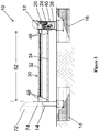
- the barrier assembly 10 in accordance with at least one aspect of the invention provides a pair of spaced apart stanchions 12 and 14 each rigidly mounted on a secure footing 16, such as reinforced cement mounting pads.
- the stanchions include a primary stanchion 12 with fully self-contained hydraulic and electronic controls 20 (discussed in greater detail below) and a secondary stanchion 14 spaced apart from the primary stanchion 12.
- a dual barrier arm assembly 30 has upper and lower arms 32 and 34 that span between the primary and secondary stanchions 12 and 14.
- the primary and secondary stanchions 12 and 14 of the illustrated embodiment are configured for use with a shallow mount footing 16 that reduces the installation time and that reduces the impact of utilities, water table, and other site concerns during installation of the barrier assembly.
- the plate mount design also allows a foundation construction to be used independent of other equipment installation. The self-contained controls and hydraulics reduce the need for expensive and time-consuming trenching of hydraulic hoses, wiring, etc., to a remote control panel.
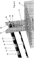
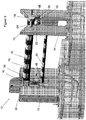
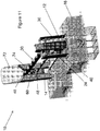
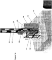
- the self-contained controls 20 include a hydraulic system 22 and an electrical control system 24, as illustrated in Figures 3-5 , 10 , 11 , and 14 . These controls are configured to pivotally move the upper and lower barrier arms 32 and 34 between a horizontal, lowered position and a raised position.
- the hydraulic system 22 and the electronic control system 24 are fully enclosed and self-contained in the primary stanchion 12. As seen in Figures 3 and 4 , the hydraulic system 22 is fully contained in a receptacle area 36 on one side of the primary stanchion's housing 38, and the electronic control system 24 is fully contained in a receptacle area 40 on the other side of the primary stanchion's housing 38. While the illustrated embodiment shows the hydraulic system 22 and the electronic control system 24 in separate receptacle areas in the housing 38, other embodiments can include the fully contained hydraulic and electronic systems 22 and 24 in other areas or a combined area within the primary stanchion 12.
- the hydraulic system 22 is configured to generate an optimized motion of the barrier arms 32 and 34 and to enable high speed and ultra smooth operation of the arms without banging or providing excess wear on the components.
- the hydraulic system 22 is a double acting hydraulic system that opens the barrier arms 32 and 34 to substantially a full vertical position.
- the hydraulic system 22 also allows for hydraulic locking of the barrier arms 32 and 34 in the closed position, thereby eliminating the need for external locking devices for the arms during normal operation between the lowered and raised positions.
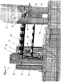
- the electronic control system 24 of the illustrated embodiment, shown in Figure 5 includes a microprocessor-based control board, sold under the trade name Smart Touch ControllerTM.
- This microprocessor-based control board supplies an extensive feature set along with an RS -- 485-based command and control interface.
- the Smart Touch ControllerTM and keypad are conveniently and cost effectively mounted inside a controller portion 42 of the primary stanchion 12.
- the electronics system 24 is configured to integrate with access control devices and security systems and to easily synchronize with other gate operators, crash gates, and accessories.
- An encoder 44 senses continuous arm position and enables precise motion control without the use of exposed mechanical limit switches.
- the electronic control system 24 can also connect to a lap top computer using a conventional computer interface to upload the operator software, download fault logs, and generate diagnostics.
- the upper and lower barrier arms 32 and 34 are parallel and spaced apart from each other.
- the upper and lower barrier arms 32 and 34 are disposed in a substantially vertical plane, such that the upper arm 32 is positioned vertically above the lower arm 34.
- the upper and lower arms 32 and 34 are interconnected only at the proximal and distal ends 46 and 48 and are pivotally movable upon activation of the hydraulic system 22 between the lowered and raised positions.
- the upper and lower arms 32 and 34 pivot as a unit at the primary stanchion 12 between the lowered and raised positions.
- the proximal end 46 of the upper and lower arms 32 and 34 are each securely connected to the mounting structure 50 of the primary stanchion 12 and the mounting structure is attached to the hydraulic system 22.
- the upper and lower arms 32 and 34 each have a free distal end 48 received by the secondary stanchion 14 when the arms 32 and 34 are moved to the lowered position.
- the free distal ends 48 of the upper and lower arms 32 and 34 are lifted upwardly and away from the second stanchion 14 along an arc, and the arms are moved to a vertical orientation, thereby moving the arms away from the space between the primary and secondary stanchions 12 and 14.
- the arms 32 and 34 When the upper and lower arms 32 and 34 are in the lowered position, the arms 32 and 34 are substantially horizontal and extend fully across the space 52 between the primary and secondary stanchions 12 and 14, thereby blocking vehicles or the like from passing through the fortified gate.
- the upper arm 32 In the lowered position, the upper arm 32 is positioned at a selected height above the ground so that, when a vehicle is at the gate, the upper arm 32 will block the vehicle from passing between the stanchions 12 and 14.
- the upper arm 32 is a reinforced arm structure with an internal rigid bar 54 with an outer case 56.
- the upper arm 32 and the stanchions 12 and 14 are configured to provide the requisite stopping force in the event a larger vehicle, such as a 15,000 Ibs (6.8 metric ton) medium-duty truck, intentionally or accidentally crashes into the arm.
- the upper arm 32 is positioned to block and/or engage the body or frame of the medium-duty truck when in the lowered position.
- the fortified stanchions 12 and 14 securely support the proximal and distal ends 46 and 48 of the upper arm 32 in the lowered position to retain the arm across the space 52 between the stanchions 12 and 14 and to provide the stopping force to the vehicle.
- the lower arm 34 is spaced below the upper arm 32 and is arranged at a distance above the ground that will block, engage, and stop the body or frame of a smaller vehicle, such as a passenger vehicle, in the event it crashes into the barrier assembly 10.
- the position of the lower arm 34 blocks the smaller vehicle from passing fully between the stanchions 12 and 14 with sufficient stopping force.
- the upper arm 32 is positioned to be aligned approximately with the windshield and/or top portion of the smaller vehicle. If the lower arm 34 was not provided, a smaller vehicle could pass partially under the upper arm 32, such that the upper arm 32 would engage the windshield or roof area of the vehicle. By allowing a vehicle to even partially extend under the upper arm 32 would be an unacceptable breach between the stanchions 12 and 14.
- the lower arm 34 of the dual arm assembly 30 in accordance with the current embodiment is positioned to provide the blocking and stopping force for the body or frame of the smaller vehicle before the smaller vehicle contacts or engages the upper arm 32. Accordingly, the lower arm 34 provides a structure that the smaller vehicle may engage first, such as upon an accidental or intentional impact with the barrier arms 32 and 34. The lower arm 34 will also help protect the smaller vehicle from excessive damage to the windshield and roof area by the upper arm 32, particularly in the event of an inadvertent impact with the fortified barrier assembly 10.
- the upper and lower arms 32 and 34 are joined together at their distal ends 48 by a linkage assembly 60 that allows both upper and lower arms 32 and 34 to move simultaneously between the lowered and upper position.
- the lower arm 34 is positioned relative to the upper arm 32 such that, when a truck attempts to crash through the barrier arms 32 and 34, the body or frame of the truck may partially pass over the top of the lower arm 34 as the vehicle crashes into the arms.
- the weight of the vehicle on the lower arm 34 will hold the lower arm in the lowered position. Accordingly, by structurally joining the free distal ends 48 of the upper and lower arms 32 and 34, the weight of the vehicle pressing down on the lower arm 34 also hold the reinforced upper arm 32 to also be held down in the lowered position.
- the barrier assembly 10 of the present invention also includes retention structures 62 in the secondary stanchion 14 positioned to receive and engage a retention bar 64 mounted on the distal end 48 of the upper arm 32 when a vehicle crashes into the arms 32 and 34.
- This engagement between the retention structure 62 and the retention bar 64 effectively lock the distal ends 48 of the upper and lower arms 32 and 34 in the lowered position.
- the retention structures 62 include C-shaped brackets 66 positioned slightly longitudinally away from the distal ends 48 of the upper and lower arms 32 and 34. The C-shaped brackets 66 are positioned with the opening of the bracket facing toward the retention bar 64 on the distal end 48 of the upper arm 32.
- the retention bar 64 is perpendicular to the longitudinal axis of the upper arm 32 and in alignment with the openings of the C-shaped brackets 66.
- the upper arm 32 may bend or buckle and draw the retention bar 64 longitudinally rearward toward the primary stanchion, thereby drawing the retention bar into the C-shaped brackets 66 through the bracket openings.
- the brackets engage the retention bar 64 and prevent vertical motion of the upper and lower arms 32 and 34 away from the lowered position.
- the fortified secondary stanchion 14 provides the anchoring force to hold the distal ends 48 of the arms 32 and 34 in place and to withstand the forces of a vehicle crashing into the upper and lower arms 32 and 34, thereby preventing breach between the stanchions 12 and 14.
- the retention bar 64 When the upper and lower arms 32 and 34 are operating in a normal fashion through movement between the lowered and raised positions, the retention bar 64 is spaced longitudinal forward of the retention brackets 66. The free distal ends 48 are therefore free to move into and out of the secondary stanchion 14 as the arms 32 and 34 move between the raised and lowered positions.
- the linkage 60 at the distal ends 48 of the upper and lower arms 32 and 34 help maintain the lateral stability of the arms throughout their motion between the lowered and raised positions. This arrangement, in conjunction with the fully contained hydraulic and electronics systems 22 and 24 in the primary stanchion 12, allows for very fast arm speed while moving between the lowered and raised positions.
- the fast arm speed also allows for fast arm deployment in response to a threat, such as during an "emergency fast close" condition.
- the dual arm barrier assembly 10 of the illustrated embodiment includes a plurality of LED lights 70 embedded along the upper arm 32 to provide a visual indicator or a visual identifier to vehicles approaching the arms when in the lowered position.
- the LED arm lights 70 are controlled by the electronic control system 24.
- the electronic control system 24 can be programmed to turn on or off the LED lights 70 in accordance with a selected program.
- the lights 70 can also be configured to flash, such as when the arms 32 and 34 are to be raised and/or lowered.
- the illustrated embodiment also can be configured with a stoplight assembly connected to, as an example, the primary stanchion 12, to provide a stop/go indicator to a vehicle seeking to pass between the stanchions 12 and 14 during normal use and operation.
- an entrapment shield 72 is connected to the top portion 74 of the secondary stanchion 14. This entrapment shield 72 extends around the open top area of the secondary stanchion 14 where the lower and upper arms 32 and 34 pass into and out of the secondary stanchion structure. The entrapment shield 72 does not interfere with movement of the upper and lower arms 32 and 34 during normal operation. The entrapment shield 72 does, however, provide a blocking structure that blocks pedestrians from reaching into the space in the secondary stanchion 14 through which the lower and upper arms 32 and 34 pass. Other embodiments can be provided without the entrapment shield or with other structures that helps protect the secondary stanchion 14 and the free distal ends 48 of the upper and/or lower arms 32 and 34.
Landscapes
- Engineering & Computer Science (AREA)
- Architecture (AREA)
- Civil Engineering (AREA)
- Structural Engineering (AREA)
- Physics & Mathematics (AREA)
- General Physics & Mathematics (AREA)
- Mechanical Engineering (AREA)
- Refuge Islands, Traffic Blockers, Or Guard Fence (AREA)
- Window Of Vehicle (AREA)
Description
- This non-provisional patent application claims priority to and the benefit of
U.S. Provisional Patent Application No. 61/537,183, filed September 21, 2011 - Embodiments of the present invention are directed to barriers, and more particularly to drop arm or vertical pivot gates.
- Conventional fortified barriers are designed to control traffic (vehicular or otherwise), while also deterring potential threats by vehicles to personnel and/or property. Fortified barriers configured to stop unwanted intruders from a secure area are often used in association with key assets, such as government installations, petrochemical facilities, and other protected locations. One such type of fortified barrier is a vertical pivot or drop arm gate that typically includes an arm pivotally connected at one end to a support housing. The pivot arm can rotate between a lowered blocking position and a raised, open position. The arm is typically positioned horizontally at a height that would effectively engage and restrain a medium duty truck trying to crash through the gate. This height of the arm is often at a level that may allow a smaller vehicle to pass at least partially under the arm and/or apply a vertical lifting force to the arm when the windshield and/or upper portion of the vehicle crashes into the arm, purposely or accidentally. There is a need for improved fortified barrier systems.
US 6,857,227 B discloses a pivoting crash barrier for arresting and impacting vehicle wherein the crash barrier gate is pivotally supported on a horizontal shaft while an engagement stanchion engageable by the outer tip of the lowered gate supports the lowered gate on the second post side of a roadway. The crash barrier gate has a latch on the engagement stanchion side that prevents inadvertent gate movement due to uplift forces and a pin engagement detent provided on the engagement stanchion which engages a crossbar at a distal and of the barrier when the barrier is deformed during the impact of a vehicle.
US 6,119,399 A discloses a parallelogram gate for controlling traffic on a roadway comprising an arm assembly rotatable between a raised position and a blocking position, a C-shaped barrier post, a housing and a drive assembly within the housing. The arm assembly has parallel, elongated upper and lower rails and a plurality of spaced apart pickets pivotally attached to the upper and lower rails. When in the lowered position, a distal end of the barrier arm engages the C-shaped barrier post.
US 5,459,963 A discloses a barrier for a loading dock to prevent vehicular of foot traffic from falling of the end of a loading dock which comprises a movable gate and an additional bar below the gate coupled to the gate by a pivotable link such that the gate and the bar are parallelly moved from the open to the closed position and vice versa. - The present invention provides a barrier assembly with the features of claim 1 that resolves drawbacks experienced in the prior art and provides other benefits.
-
-
Figure 1 is an isometric view of a barrier assembly in accordance with an embodiment of the present invention. -
Figure 2 is a schematic illustration of the barrier assembly ofFigure 1 . -
Figure 3 is a schematic front elevation view of the barrier assembly ofFigure 1 . -
Figure 4 is an enlarged isometric view of a primary stanchion and hydraulic controls of the barrier assembly ofFigure 1 . -
Figure 5 is an enlarged isometric view of the primary stanchion and electronic controls of the barrier assembly ofFigure 1 . -
Figure 6 is a schematic perspective view of the barrier assembly with primary and secondary stanchions mounted in secure footings. -
Figure 7 is a schematic perspective view of the barrier assembly ofFigure 6 with a shield removed from a second stanchion for purposes of illustration. -
Figure 8 is an enlarged bottom perspective view of the second stanchion and the free distal end of the upper barrier arm of the assembly ofFigure 6 . -
Figure 9 is a perspective view of the barrier assembly ofFigure 6 with the shield removed from the second stanchion for purposes of clarity. -
Figure 10 is a perspective view of the barrier assembly ofFigure 6 with the shield on the second stanchions shown in phantom lines, and housing the panels should be removed from the first stanchion to illustrate the hydraulic system connected to the upper and lower barrier arms. -
Figure 11 is a side perspective view of the barrier assembly ofFigure 10 . -
Figure 12 is an enlarged, partial perspective view of the barrier assembly ofFigure 6 showing a linkage at the distal ends of the upper and lower barrier arms. -
Figure 13 is a perspective view of the barrier assembly ofFigure 6 with the barrier arms shown in the open, raised position. -
Figure 14 is an enlarged perspective view of the first stanchion of the barrier assembly ofFigure 13 with housing panels removed to show the hydraulic system in the first stanchion. -
Figure 15 is a perspective view of the barrier assembly ofFigure 6 with the barrier arms shown in the open, raised position. -
Figure 16 is an enlarged perspective view of the second stanchion of the barrier assembly ofFigure 6 . - The present disclosure describes a barrier assembly in accordance with certain embodiments of the present invention. Several specific details of the invention are set forth in the following description and the Figures to provide a thorough understanding of certain embodiments of the invention. One skilled in the art, however, will understand that the present invention may have additional embodiments, and that other embodiments of the invention may be practiced without several of the specific features described below.
- As seen in
Figures 1-3 , thebarrier assembly 10 in accordance with at least one aspect of the invention provides a pair of spaced apartstanchions secure footing 16, such as reinforced cement mounting pads. The stanchions include aprimary stanchion 12 with fully self-contained hydraulic and electronic controls 20 (discussed in greater detail below) and asecondary stanchion 14 spaced apart from theprimary stanchion 12. A dualbarrier arm assembly 30 has upper andlower arms secondary stanchions - The primary and
secondary stanchions shallow mount footing 16 that reduces the installation time and that reduces the impact of utilities, water table, and other site concerns during installation of the barrier assembly. The plate mount design also allows a foundation construction to be used independent of other equipment installation. The self-contained controls and hydraulics reduce the need for expensive and time-consuming trenching of hydraulic hoses, wiring, etc., to a remote control panel. - The self-contained
controls 20 include ahydraulic system 22 and anelectrical control system 24, as illustrated inFigures 3-5 ,10 ,11 , and14 . These controls are configured to pivotally move the upper andlower barrier arms hydraulic system 22 and theelectronic control system 24 are fully enclosed and self-contained in theprimary stanchion 12. As seen inFigures 3 and4 , thehydraulic system 22 is fully contained in areceptacle area 36 on one side of the primary stanchion'shousing 38, and theelectronic control system 24 is fully contained in areceptacle area 40 on the other side of the primary stanchion'shousing 38. While the illustrated embodiment shows thehydraulic system 22 and theelectronic control system 24 in separate receptacle areas in thehousing 38, other embodiments can include the fully contained hydraulic andelectronic systems primary stanchion 12. - The
hydraulic system 22 is configured to generate an optimized motion of thebarrier arms hydraulic system 22 is a double acting hydraulic system that opens thebarrier arms hydraulic system 22 also allows for hydraulic locking of thebarrier arms - The
electronic control system 24 of the illustrated embodiment, shown inFigure 5 , includes a microprocessor-based control board, sold under the trade name Smart Touch Controller™. This microprocessor-based control board supplies an extensive feature set along with an RS -- 485-based command and control interface. The Smart Touch Controller™ and keypad are conveniently and cost effectively mounted inside acontroller portion 42 of theprimary stanchion 12. Theelectronics system 24 is configured to integrate with access control devices and security systems and to easily synchronize with other gate operators, crash gates, and accessories. Anencoder 44 senses continuous arm position and enables precise motion control without the use of exposed mechanical limit switches. Theelectronic control system 24 can also connect to a lap top computer using a conventional computer interface to upload the operator software, download fault logs, and generate diagnostics. - As shown in
Figures 6 and7 , the upper andlower barrier arms lower barrier arms upper arm 32 is positioned vertically above thelower arm 34. The upper andlower arms distal ends hydraulic system 22 between the lowered and raised positions. The upper andlower arms primary stanchion 12 between the lowered and raised positions. Theproximal end 46 of the upper andlower arms structure 50 of theprimary stanchion 12 and the mounting structure is attached to thehydraulic system 22. The upper andlower arms distal end 48 received by thesecondary stanchion 14 when thearms lower arms lower arms second stanchion 14 along an arc, and the arms are moved to a vertical orientation, thereby moving the arms away from the space between the primary andsecondary stanchions - When the upper and
lower arms arms space 52 between the primary andsecondary stanchions upper arm 32 is positioned at a selected height above the ground so that, when a vehicle is at the gate, theupper arm 32 will block the vehicle from passing between thestanchions upper arm 32 is a reinforced arm structure with an internalrigid bar 54 with anouter case 56. Theupper arm 32 and thestanchions upper arm 32 is positioned to block and/or engage the body or frame of the medium-duty truck when in the lowered position. Thefortified stanchions distal ends upper arm 32 in the lowered position to retain the arm across thespace 52 between thestanchions - The
lower arm 34 is spaced below theupper arm 32 and is arranged at a distance above the ground that will block, engage, and stop the body or frame of a smaller vehicle, such as a passenger vehicle, in the event it crashes into thebarrier assembly 10. The position of thelower arm 34 blocks the smaller vehicle from passing fully between thestanchions upper arm 32 is positioned to be aligned approximately with the windshield and/or top portion of the smaller vehicle. If thelower arm 34 was not provided, a smaller vehicle could pass partially under theupper arm 32, such that theupper arm 32 would engage the windshield or roof area of the vehicle. By allowing a vehicle to even partially extend under theupper arm 32 would be an unacceptable breach between thestanchions stanchions upper arm 32 would actually impart a vertical lifting force to the upper arm, which has the possibility of allowing the smaller vehicle to pass even further under the upper arm. - The
lower arm 34 of thedual arm assembly 30 in accordance with the current embodiment is positioned to provide the blocking and stopping force for the body or frame of the smaller vehicle before the smaller vehicle contacts or engages theupper arm 32. Accordingly, thelower arm 34 provides a structure that the smaller vehicle may engage first, such as upon an accidental or intentional impact with thebarrier arms lower arm 34 will also help protect the smaller vehicle from excessive damage to the windshield and roof area by theupper arm 32, particularly in the event of an inadvertent impact with thefortified barrier assembly 10. - As seen in
Figures 9-12 , the upper andlower arms distal ends 48 by alinkage assembly 60 that allows both upper andlower arms lower arm 34 is positioned relative to theupper arm 32 such that, when a truck attempts to crash through thebarrier arms lower arm 34 as the vehicle crashes into the arms. The weight of the vehicle on thelower arm 34 will hold the lower arm in the lowered position. Accordingly, by structurally joining the free distal ends 48 of the upper andlower arms lower arm 34 also hold the reinforcedupper arm 32 to also be held down in the lowered position. - As seen in
Figures 7-10 ,15 , and16 thebarrier assembly 10 of the present invention also includesretention structures 62 in thesecondary stanchion 14 positioned to receive and engage aretention bar 64 mounted on thedistal end 48 of theupper arm 32 when a vehicle crashes into thearms retention structure 62 and theretention bar 64 effectively lock the distal ends 48 of the upper andlower arms retention structures 62 include C-shapedbrackets 66 positioned slightly longitudinally away from the distal ends 48 of the upper andlower arms brackets 66 are positioned with the opening of the bracket facing toward theretention bar 64 on thedistal end 48 of theupper arm 32. Theretention bar 64 is perpendicular to the longitudinal axis of theupper arm 32 and in alignment with the openings of the C-shapedbrackets 66. When a vehicle or the like crashes into the upper andlower arms upper arm 32 may bend or buckle and draw theretention bar 64 longitudinally rearward toward the primary stanchion, thereby drawing the retention bar into the C-shapedbrackets 66 through the bracket openings. Once theretention bar 64 is moved into thebrackets 66, the brackets engage theretention bar 64 and prevent vertical motion of the upper andlower arms secondary stanchion 14 provides the anchoring force to hold the distal ends 48 of thearms lower arms stanchions - When the upper and
lower arms retention bar 64 is spaced longitudinal forward of theretention brackets 66. The free distal ends 48 are therefore free to move into and out of thesecondary stanchion 14 as thearms linkage 60 at the distal ends 48 of the upper andlower arms electronics systems primary stanchion 12, allows for very fast arm speed while moving between the lowered and raised positions. Such increased speed helps to reduce traffic backup by minimizing the gate open time, thereby allowing more authorized vehicles per hour to pass through the fortified gate assembly. The fast arm speed also allows for fast arm deployment in response to a threat, such as during an "emergency fast close" condition. - The dual
arm barrier assembly 10 of the illustrated embodiment includes a plurality ofLED lights 70 embedded along theupper arm 32 to provide a visual indicator or a visual identifier to vehicles approaching the arms when in the lowered position. TheLED arm lights 70 are controlled by theelectronic control system 24. Theelectronic control system 24 can be programmed to turn on or off the LED lights 70 in accordance with a selected program. Thelights 70 can also be configured to flash, such as when thearms primary stanchion 12, to provide a stop/go indicator to a vehicle seeking to pass between thestanchions - In the embodiment illustrated in
Figures 1 and6 , anentrapment shield 72 is connected to thetop portion 74 of thesecondary stanchion 14. Thisentrapment shield 72 extends around the open top area of thesecondary stanchion 14 where the lower andupper arms entrapment shield 72 does not interfere with movement of the upper andlower arms entrapment shield 72 does, however, provide a blocking structure that blocks pedestrians from reaching into the space in thesecondary stanchion 14 through which the lower andupper arms secondary stanchion 14 and the free distal ends 48 of the upper and/orlower arms - From the foregoing, it will be appreciated that specific embodiments of the invention have been described herein for purposes of illustration, but that various modifications may be made without deviating from the invention. Additionally, aspects of the invention described in the context of particular embodiments or examples may be combined or eliminated in other embodiments. Although advantages associated with certain embodiments of the invention have been described in the context of those embodiments, other embodiments may also exhibit such advantages. Additionally, not all embodiments need necessarily exhibit such advantages to fall within the scope of the invention. Accordingly, the invention is not limited except as by the appended claims.
Claims (10)
- A barrier assembly (10) for controlling passing of a vehicle, comprising:first (12) and second stanchions (14),retention structures (62) in the second stanchion (14),first (32) and second barrier arms (34) being pivotally connected to the first stanchion (12) for movement between closed and open positions , wherein the first barrier arm (32) in the closed position is spaced above the second barrier arm (34); the second barrier arm (34) in the closed position is located at a selected height relative to the vehicle such that at least a portion of such passing vehicle will extend over the second barrier arm (34) and block the second barrier arm (34) from moving upwardly away toward the open position when the vehicle engages the first (32) or second barrier arm (34), thereby preventing the first barrier arm (32) from being moved out of a blocking position spanning between the first (12) and second stanchions (14) due to a structural interconnection between said first and second barrier arms (31, 34); anda retention bar (64) connected to the distal end (48) of the first barrier arm (32) and oriented perpendicular to a longitudinal axis of the first barrier arm (32),characterized in that:the retention structures (62) include C-shaped brackets (66) being, when the first (32) and second barrier arms (34) are in the closed position, positioned slightly longitudinally away from the distal ends (48) of the first and second barrier arms (32, 34), with bracket openings facing toward the retention bar (64), the retention bar (64) being out of engagement with said C-shaped brackets (66) and in vertical alignment with the bracket openings;the first (32) and second barrier arms (34) being structurally interconnected to each other only at proximal (46) and distal end portions (48), wherein the first barrier arm (32) and the retention bar (64) are adapted so that when a vehicle crashes with sufficient force into the first (32) and second barrier arms (34) in said closed position, the first barrier arm (32) bends and draws the retention bar (64) longitudinally rearward towards the first stanchion (12) through the bracket openings and into the C-shaped brackets (66) such that the C-shaped brackets (66) engage the retention bar (64) and prevent vertical movement of the first (32) and second barrier arms (34) away from said closed position.
- The assembly of claim 1 further comprising hydraulic (22) and electronic controls (24) fully contained in at least one of the first (12) and second stanchions (14), the hydraulic (22) and electronic controls (24) being coupled to the first (32) and second barrier arms (34) and configured to control movement of the first (32) and second barrier arms (34) between the closed and open positions.
- The assembly of claim 2, wherein the hydraulic (22) and electronic controls (24) are fully contained in the first stanchion (12).
- The assembly of claim 2, wherein the electronic control system (24) is fully contained in the first stanchion (12).
- The assembly of one of the preceding claims, wherein the first barrier arm (32) is positioned vertically above the second barrier arm (34) defining a plane along which the first (32) and second barrier arms (34) pivotally move through an arc as the first (32) and second barrier arms (34) move between the closed and open positions.
- The assembly of one of the preceding claims, wherein the first (32) and second barrier arms (34) are parallel and pivotable through an arc relative to the first stanchion (12) when moving between the closed and open positions.
- The assembly of one of the preceding claims, wherein the first (32) and second barrier arms (34) have a linkage member (60) interconnecting the distal end portions (68) of the first (32) and second barrier arms (34), the linkage assembly (60) allows the first (32) and second barrier arms (34) to move together as a unit between the closed and open positions.
- The assembly of claim 2, wherein the first stanchion (12) has a pivotable mounting structure (50) coupled to the hydraulic (22) and electronic controls (24), and the proximal end portions (48) of the first (32) and second barrier arms (34) are securely connected to a mounting structure (50).
- The assembly of one of the preceding claims, further comprising a shield (72) connected to the top portion (74) of the second stanchion (14) and extending around an open top area of the second stanchion (14) in which the distal end portions (68) of the first (32) and second barrier arms (34) pass into and out of the second stanchion (14).
- The assembly of one of the preceding claims, wherein the distal end portions (48) of the first (32) and second barrier arms (34) are received by the second stanchion (14) when the first (32) and second barrier arms (34) are moved to the closed position, and when the first (32) and second barrier arms (34) are operating in normal fashion through movement between the closed and open position, the retention bar (64) is spaced longitudinally forward of the C-shaped brackets (66), and the distal end portions (48) are free to move into and out of the secondary stanchion (14) as the first (32) and second barrier arms (34) move between the open and closed positions.
Applications Claiming Priority (2)
| Application Number | Priority Date | Filing Date | Title |
|---|---|---|---|
| US201161537183P | 2011-09-21 | 2011-09-21 | |
| PCT/US2012/056729 WO2013044148A2 (en) | 2011-09-21 | 2012-09-21 | Dual arm fortified barrier assembly |
Publications (3)
| Publication Number | Publication Date |
|---|---|
| EP2773816A2 EP2773816A2 (en) | 2014-09-10 |
| EP2773816A4 EP2773816A4 (en) | 2015-08-12 |
| EP2773816B1 true EP2773816B1 (en) | 2017-11-08 |
Family
ID=47880797
Family Applications (1)
| Application Number | Title | Priority Date | Filing Date |
|---|---|---|---|
| EP12834021.3A Active EP2773816B1 (en) | 2011-09-21 | 2012-09-21 | Barrier assembly |
Country Status (3)
| Country | Link |
|---|---|
| US (2) | US20130071182A1 (en) |
| EP (1) | EP2773816B1 (en) |
| WO (1) | WO2013044148A2 (en) |
Families Citing this family (24)
| Publication number | Priority date | Publication date | Assignee | Title |
|---|---|---|---|---|
| CN104821092B (en) * | 2015-05-21 | 2017-05-31 | 姜玉兰 | The implementation method of wind light mutual complementing formula vehicle pass-through limit for height |
| WO2016196852A1 (en) | 2015-06-05 | 2016-12-08 | Neusch Innovations, Lp | Anti-ram sliding crash gate |
| US10208440B1 (en) | 2015-09-09 | 2019-02-19 | Safe Rack Llc | Traffic gate |
| RU167964U1 (en) * | 2016-07-07 | 2017-01-13 | Александр Вячеславович Кожевников | MOBILE SLIDING BAR |
| US10900181B2 (en) * | 2017-06-19 | 2021-01-26 | Neusch Innovations, Lp | Portable drop arm vehicle barrier |
| USD925774S1 (en) * | 2019-07-08 | 2021-07-20 | Synergy Group LLC | ATM security structure |
| US11189138B2 (en) | 2019-07-08 | 2021-11-30 | Synergy Group LLC | ATM security apparatus and method of use |
| GB2588208B (en) * | 2019-10-16 | 2023-08-16 | Gme Springs Ltd | Surface mount security gate system |
| CN110804964B (en) * | 2019-10-22 | 2021-10-26 | 北京大友可为信息技术集团有限公司 | Automatic roadblock picking and placing method and system based on artificial intelligence |
| CN110827420B (en) * | 2019-11-18 | 2020-08-28 | 乐清市通达有线电厂 | Parking charge entrance guard automatic switch equipment |
| US11598059B2 (en) * | 2020-09-09 | 2023-03-07 | Multi-Fab Products, Llc | Gate safety barrier assembly |
| CN113160591A (en) * | 2021-03-25 | 2021-07-23 | 安徽银徽科技有限公司 | Signal lamp management equipment and intelligent traffic operation and maintenance platform based on same |
| RU2759250C1 (en) * | 2021-06-01 | 2021-11-11 | Акционерное общество "Научно-производственное объединение специальных материалов" (АО "НПО Спецматериалов") | Anti-ram type barrier |
| CN114032810A (en) * | 2021-11-04 | 2022-02-11 | 张爱民 | Working method of intelligent door gate for vehicle |
| US11377899B1 (en) * | 2021-12-14 | 2022-07-05 | Frogparking Limited | Vehicle barrier gate system |
| GB2614306B (en) * | 2021-12-24 | 2024-01-03 | A Safe Hq Ltd | Dock gate barrier system |
| EP4239602A1 (en) * | 2022-03-02 | 2023-09-06 | Skidata GmbH | Blocking element, access control device and system |
| US11821155B1 (en) | 2022-11-17 | 2023-11-21 | Frogparking Limited | Vehicle barrier gate system |
| WO2025078661A1 (en) * | 2023-10-13 | 2025-04-17 | Boplan Bv | Automated dock gate system |
| DE102023128030A1 (en) * | 2023-10-13 | 2025-04-17 | Belfox Torautomatik Gmbh | Drive for barrier system |
| US12312755B1 (en) * | 2024-01-12 | 2025-05-27 | Foster Fence, Ltd. | High collision force resistant gate |
| BE1032578B1 (en) * | 2024-04-26 | 2025-12-01 | Boplan Bv | LOADING DOCK GATE WITH INCREASED IMPACT RESISTANCE FOR RAIL AND POLES |
| US20250389094A1 (en) * | 2024-06-25 | 2025-12-25 | Ameristar Perimeter Security Usa Inc. | Drop-Arm Barrier |
| US12428794B1 (en) * | 2024-06-28 | 2025-09-30 | David Chamberlin | Boat slip barrier |
Family Cites Families (21)
| Publication number | Priority date | Publication date | Assignee | Title |
|---|---|---|---|---|
| BE371306A (en) * | ||||
| US2563894A (en) * | 1945-12-05 | 1951-08-14 | Kremser A | Mechanically operated gate |
| US4658543A (en) * | 1985-07-03 | 1987-04-21 | Carr Frederick J | Swinging lift gate |
| US4941284A (en) * | 1989-12-15 | 1990-07-17 | David Stoller | Parking space barrier |
| US5299386A (en) * | 1991-11-27 | 1994-04-05 | Rite-Hite Corporation | Safety gate assembly |
| US5288164A (en) * | 1992-01-07 | 1994-02-22 | Nasatka Ralph G | Combined vehicle barrier |
| US5459963A (en) * | 1993-12-16 | 1995-10-24 | The Serco Corporation | Safety gate for loading docks |
| US5975791A (en) * | 1997-03-04 | 1999-11-02 | Mcculloch; G. Wallace | Vehicle security gate apparatus and method of operating same |
| US5984569A (en) * | 1998-03-09 | 1999-11-16 | Chou; Pi-Cheng | Gate barrier |
| US6115963A (en) * | 1998-09-24 | 2000-09-12 | B & B Electromatic, Inc. | Crossing guard |
| US6119399A (en) * | 1999-02-09 | 2000-09-19 | Mccain; Roy L. | Channel guided parallelogram gate |
| US6150958A (en) * | 1999-06-17 | 2000-11-21 | Criminalistics, Inc. | Remote controlled parking barrier apparatus |
| US6618993B2 (en) * | 2001-03-19 | 2003-09-16 | Thomas J. Burke | Railroad grade crossing assembly |
| US6857227B2 (en) * | 2002-02-28 | 2005-02-22 | Automatic Power, Inc. | Vehicle crash barrier |
| WO2005049925A1 (en) * | 2003-11-18 | 2005-06-02 | Safecross Pty Ltd | Portable boom gate apparatus |
| US7098807B2 (en) * | 2003-11-19 | 2006-08-29 | 9076-0935 Quebec Inc. | Traffic-signaling system |
| US8033053B2 (en) * | 2004-02-12 | 2011-10-11 | Performance Development Corporation | Security barrier system |
| US7467909B2 (en) * | 2006-03-30 | 2008-12-23 | Engineered Arresting Systems Corporation | Arresting systems and methods |
| US7739834B2 (en) * | 2006-06-19 | 2010-06-22 | Garlock Equipment Company | Cantilever gate |
| GB0717841D0 (en) * | 2007-09-13 | 2007-10-24 | Highway Care Ltd | Barrier system |
| WO2010093797A1 (en) * | 2009-02-11 | 2010-08-19 | Universal Safety Response, Inc. | Vehicle barrier with release mechanism |
-
2012
- 2012-09-21 EP EP12834021.3A patent/EP2773816B1/en active Active
- 2012-09-21 US US13/624,754 patent/US20130071182A1/en not_active Abandoned
- 2012-09-21 WO PCT/US2012/056729 patent/WO2013044148A2/en not_active Ceased
-
2015
- 2015-03-09 US US14/642,626 patent/US9822501B2/en active Active
Non-Patent Citations (1)
| Title |
|---|
| None * |
Also Published As
| Publication number | Publication date |
|---|---|
| WO2013044148A3 (en) | 2014-05-15 |
| US20130071182A1 (en) | 2013-03-21 |
| US9822501B2 (en) | 2017-11-21 |
| US20160002870A1 (en) | 2016-01-07 |
| WO2013044148A2 (en) | 2013-03-28 |
| EP2773816A4 (en) | 2015-08-12 |
| EP2773816A2 (en) | 2014-09-10 |
Similar Documents
| Publication | Publication Date | Title |
|---|---|---|
| US9822501B2 (en) | Dual arm fortified barrier assembly | |
| US8740495B1 (en) | Shallow flush-mounted vehicle control barrier | |
| US10618392B2 (en) | Construction machine with operating platform and access control | |
| US4705426A (en) | Security and defense barrier | |
| US6702512B1 (en) | Vehicle arresting installation | |
| KR20110104985A (en) | Vehicle traffic control | |
| JP5828831B2 (en) | Access device | |
| US6843614B2 (en) | Portable security system | |
| US20190292739A1 (en) | Safety Trailer | |
| KR920006426B1 (en) | Barrier post free of jamming points | |
| CN1837488B (en) | Safety barrier | |
| US20130031839A1 (en) | Multiple direction railroad gate release mechanism | |
| US20080226391A1 (en) | High Impact Gate | |
| KR102332754B1 (en) | Vehicle fall prevention device | |
| US6289634B1 (en) | Crossing guard | |
| US20160160459A1 (en) | Arresting fence system | |
| US20180148906A1 (en) | A safety barrier | |
| GB2282838A (en) | Retractable traffic control barrier | |
| US11598059B2 (en) | Gate safety barrier assembly | |
| RU2333308C1 (en) | Anti-ram barrier | |
| US7237979B2 (en) | Security barrier | |
| EP2605633B1 (en) | Panel arrangement for a harvesting machine | |
| GB2350387A (en) | Post arrangement | |
| US12270164B2 (en) | Terminal element of a traffic barrier device, transition system, and method for providing impact protection | |
| AU2021204529A1 (en) | Traffic boom gate mechanism |
Legal Events
| Date | Code | Title | Description |
|---|---|---|---|
| PUAI | Public reference made under article 153(3) epc to a published international application that has entered the european phase |
Free format text: ORIGINAL CODE: 0009012 |
|
| 17P | Request for examination filed |
Effective date: 20140410 |
|
| AK | Designated contracting states |
Kind code of ref document: A2 Designated state(s): AL AT BE BG CH CY CZ DE DK EE ES FI FR GB GR HR HU IE IS IT LI LT LU LV MC MK MT NL NO PL PT RO RS SE SI SK SM TR |
|
| DAX | Request for extension of the european patent (deleted) | ||
| A4 | Supplementary search report drawn up and despatched |
Effective date: 20150714 |
|
| RIC1 | Information provided on ipc code assigned before grant |
Ipc: G08G 1/095 20060101ALI20150708BHEP Ipc: E01F 13/04 20060101AFI20150708BHEP |
|
| 17Q | First examination report despatched |
Effective date: 20160817 |
|
| GRAP | Despatch of communication of intention to grant a patent |
Free format text: ORIGINAL CODE: EPIDOSNIGR1 |
|
| INTG | Intention to grant announced |
Effective date: 20170421 |
|
| GRAS | Grant fee paid |
Free format text: ORIGINAL CODE: EPIDOSNIGR3 |
|
| GRAA | (expected) grant |
Free format text: ORIGINAL CODE: 0009210 |
|
| AK | Designated contracting states |
Kind code of ref document: B1 Designated state(s): AL AT BE BG CH CY CZ DE DK EE ES FI FR GB GR HR HU IE IS IT LI LT LU LV MC MK MT NL NO PL PT RO RS SE SI SK SM TR |
|
| REG | Reference to a national code |
Ref country code: GB Ref legal event code: FG4D |
|
| REG | Reference to a national code |
Ref country code: CH Ref legal event code: EP Ref country code: AT Ref legal event code: REF Ref document number: 944278 Country of ref document: AT Kind code of ref document: T Effective date: 20171115 |
|
| REG | Reference to a national code |
Ref country code: IE Ref legal event code: FG4D |
|
| REG | Reference to a national code |
Ref country code: DE Ref legal event code: R096 Ref document number: 602012039617 Country of ref document: DE |
|
| REG | Reference to a national code |
Ref country code: NL Ref legal event code: MP Effective date: 20171108 |
|
| REG | Reference to a national code |
Ref country code: LT Ref legal event code: MG4D |
|
| REG | Reference to a national code |
Ref country code: AT Ref legal event code: MK05 Ref document number: 944278 Country of ref document: AT Kind code of ref document: T Effective date: 20171108 |
|
| PG25 | Lapsed in a contracting state [announced via postgrant information from national office to epo] |
Ref country code: LT Free format text: LAPSE BECAUSE OF FAILURE TO SUBMIT A TRANSLATION OF THE DESCRIPTION OR TO PAY THE FEE WITHIN THE PRESCRIBED TIME-LIMIT Effective date: 20171108 Ref country code: FI Free format text: LAPSE BECAUSE OF FAILURE TO SUBMIT A TRANSLATION OF THE DESCRIPTION OR TO PAY THE FEE WITHIN THE PRESCRIBED TIME-LIMIT Effective date: 20171108 Ref country code: NO Free format text: LAPSE BECAUSE OF FAILURE TO SUBMIT A TRANSLATION OF THE DESCRIPTION OR TO PAY THE FEE WITHIN THE PRESCRIBED TIME-LIMIT Effective date: 20180208 Ref country code: ES Free format text: LAPSE BECAUSE OF FAILURE TO SUBMIT A TRANSLATION OF THE DESCRIPTION OR TO PAY THE FEE WITHIN THE PRESCRIBED TIME-LIMIT Effective date: 20171108 Ref country code: SE Free format text: LAPSE BECAUSE OF FAILURE TO SUBMIT A TRANSLATION OF THE DESCRIPTION OR TO PAY THE FEE WITHIN THE PRESCRIBED TIME-LIMIT Effective date: 20171108 Ref country code: NL Free format text: LAPSE BECAUSE OF FAILURE TO SUBMIT A TRANSLATION OF THE DESCRIPTION OR TO PAY THE FEE WITHIN THE PRESCRIBED TIME-LIMIT Effective date: 20171108 |
|
| PG25 | Lapsed in a contracting state [announced via postgrant information from national office to epo] |
Ref country code: AT Free format text: LAPSE BECAUSE OF FAILURE TO SUBMIT A TRANSLATION OF THE DESCRIPTION OR TO PAY THE FEE WITHIN THE PRESCRIBED TIME-LIMIT Effective date: 20171108 Ref country code: RS Free format text: LAPSE BECAUSE OF FAILURE TO SUBMIT A TRANSLATION OF THE DESCRIPTION OR TO PAY THE FEE WITHIN THE PRESCRIBED TIME-LIMIT Effective date: 20171108 Ref country code: GR Free format text: LAPSE BECAUSE OF FAILURE TO SUBMIT A TRANSLATION OF THE DESCRIPTION OR TO PAY THE FEE WITHIN THE PRESCRIBED TIME-LIMIT Effective date: 20180209 Ref country code: HR Free format text: LAPSE BECAUSE OF FAILURE TO SUBMIT A TRANSLATION OF THE DESCRIPTION OR TO PAY THE FEE WITHIN THE PRESCRIBED TIME-LIMIT Effective date: 20171108 Ref country code: LV Free format text: LAPSE BECAUSE OF FAILURE TO SUBMIT A TRANSLATION OF THE DESCRIPTION OR TO PAY THE FEE WITHIN THE PRESCRIBED TIME-LIMIT Effective date: 20171108 Ref country code: BG Free format text: LAPSE BECAUSE OF FAILURE TO SUBMIT A TRANSLATION OF THE DESCRIPTION OR TO PAY THE FEE WITHIN THE PRESCRIBED TIME-LIMIT Effective date: 20180208 Ref country code: IS Free format text: LAPSE BECAUSE OF FAILURE TO SUBMIT A TRANSLATION OF THE DESCRIPTION OR TO PAY THE FEE WITHIN THE PRESCRIBED TIME-LIMIT Effective date: 20180308 |
|
| PG25 | Lapsed in a contracting state [announced via postgrant information from national office to epo] |
Ref country code: CZ Free format text: LAPSE BECAUSE OF FAILURE TO SUBMIT A TRANSLATION OF THE DESCRIPTION OR TO PAY THE FEE WITHIN THE PRESCRIBED TIME-LIMIT Effective date: 20171108 Ref country code: SK Free format text: LAPSE BECAUSE OF FAILURE TO SUBMIT A TRANSLATION OF THE DESCRIPTION OR TO PAY THE FEE WITHIN THE PRESCRIBED TIME-LIMIT Effective date: 20171108 Ref country code: DK Free format text: LAPSE BECAUSE OF FAILURE TO SUBMIT A TRANSLATION OF THE DESCRIPTION OR TO PAY THE FEE WITHIN THE PRESCRIBED TIME-LIMIT Effective date: 20171108 Ref country code: CY Free format text: LAPSE BECAUSE OF FAILURE TO SUBMIT A TRANSLATION OF THE DESCRIPTION OR TO PAY THE FEE WITHIN THE PRESCRIBED TIME-LIMIT Effective date: 20171108 Ref country code: EE Free format text: LAPSE BECAUSE OF FAILURE TO SUBMIT A TRANSLATION OF THE DESCRIPTION OR TO PAY THE FEE WITHIN THE PRESCRIBED TIME-LIMIT Effective date: 20171108 |
|
| REG | Reference to a national code |
Ref country code: DE Ref legal event code: R097 Ref document number: 602012039617 Country of ref document: DE |
|
| PG25 | Lapsed in a contracting state [announced via postgrant information from national office to epo] |
Ref country code: RO Free format text: LAPSE BECAUSE OF FAILURE TO SUBMIT A TRANSLATION OF THE DESCRIPTION OR TO PAY THE FEE WITHIN THE PRESCRIBED TIME-LIMIT Effective date: 20171108 Ref country code: PL Free format text: LAPSE BECAUSE OF FAILURE TO SUBMIT A TRANSLATION OF THE DESCRIPTION OR TO PAY THE FEE WITHIN THE PRESCRIBED TIME-LIMIT Effective date: 20171108 Ref country code: SM Free format text: LAPSE BECAUSE OF FAILURE TO SUBMIT A TRANSLATION OF THE DESCRIPTION OR TO PAY THE FEE WITHIN THE PRESCRIBED TIME-LIMIT Effective date: 20171108 |
|
| PLBE | No opposition filed within time limit |
Free format text: ORIGINAL CODE: 0009261 |
|
| STAA | Information on the status of an ep patent application or granted ep patent |
Free format text: STATUS: NO OPPOSITION FILED WITHIN TIME LIMIT |
|
| REG | Reference to a national code |
Ref country code: FR Ref legal event code: PLFP Year of fee payment: 7 |
|
| 26N | No opposition filed |
Effective date: 20180809 |
|
| PG25 | Lapsed in a contracting state [announced via postgrant information from national office to epo] |
Ref country code: SI Free format text: LAPSE BECAUSE OF FAILURE TO SUBMIT A TRANSLATION OF THE DESCRIPTION OR TO PAY THE FEE WITHIN THE PRESCRIBED TIME-LIMIT Effective date: 20171108 |
|
| PG25 | Lapsed in a contracting state [announced via postgrant information from national office to epo] |
Ref country code: MC Free format text: LAPSE BECAUSE OF FAILURE TO SUBMIT A TRANSLATION OF THE DESCRIPTION OR TO PAY THE FEE WITHIN THE PRESCRIBED TIME-LIMIT Effective date: 20171108 |
|
| REG | Reference to a national code |
Ref country code: CH Ref legal event code: PL |
|
| REG | Reference to a national code |
Ref country code: BE Ref legal event code: MM Effective date: 20180930 |
|
| REG | Reference to a national code |
Ref country code: IE Ref legal event code: MM4A |
|
| PG25 | Lapsed in a contracting state [announced via postgrant information from national office to epo] |
Ref country code: LU Free format text: LAPSE BECAUSE OF NON-PAYMENT OF DUE FEES Effective date: 20180921 |
|
| PG25 | Lapsed in a contracting state [announced via postgrant information from national office to epo] |
Ref country code: IE Free format text: LAPSE BECAUSE OF NON-PAYMENT OF DUE FEES Effective date: 20180921 |
|
| PG25 | Lapsed in a contracting state [announced via postgrant information from national office to epo] |
Ref country code: BE Free format text: LAPSE BECAUSE OF NON-PAYMENT OF DUE FEES Effective date: 20180930 Ref country code: CH Free format text: LAPSE BECAUSE OF NON-PAYMENT OF DUE FEES Effective date: 20180930 Ref country code: LI Free format text: LAPSE BECAUSE OF NON-PAYMENT OF DUE FEES Effective date: 20180930 |
|
| PG25 | Lapsed in a contracting state [announced via postgrant information from national office to epo] |
Ref country code: MT Free format text: LAPSE BECAUSE OF NON-PAYMENT OF DUE FEES Effective date: 20180921 |
|
| PG25 | Lapsed in a contracting state [announced via postgrant information from national office to epo] |
Ref country code: TR Free format text: LAPSE BECAUSE OF FAILURE TO SUBMIT A TRANSLATION OF THE DESCRIPTION OR TO PAY THE FEE WITHIN THE PRESCRIBED TIME-LIMIT Effective date: 20171108 |
|
| PG25 | Lapsed in a contracting state [announced via postgrant information from national office to epo] |
Ref country code: HU Free format text: LAPSE BECAUSE OF FAILURE TO SUBMIT A TRANSLATION OF THE DESCRIPTION OR TO PAY THE FEE WITHIN THE PRESCRIBED TIME-LIMIT; INVALID AB INITIO Effective date: 20120921 Ref country code: PT Free format text: LAPSE BECAUSE OF FAILURE TO SUBMIT A TRANSLATION OF THE DESCRIPTION OR TO PAY THE FEE WITHIN THE PRESCRIBED TIME-LIMIT Effective date: 20171108 |
|
| PG25 | Lapsed in a contracting state [announced via postgrant information from national office to epo] |
Ref country code: MK Free format text: LAPSE BECAUSE OF NON-PAYMENT OF DUE FEES Effective date: 20171108 |
|
| PG25 | Lapsed in a contracting state [announced via postgrant information from national office to epo] |
Ref country code: AL Free format text: LAPSE BECAUSE OF FAILURE TO SUBMIT A TRANSLATION OF THE DESCRIPTION OR TO PAY THE FEE WITHIN THE PRESCRIBED TIME-LIMIT Effective date: 20171108 |
|
| PGFP | Annual fee paid to national office [announced via postgrant information from national office to epo] |
Ref country code: DE Payment date: 20250819 Year of fee payment: 14 |
|
| PGFP | Annual fee paid to national office [announced via postgrant information from national office to epo] |
Ref country code: IT Payment date: 20250820 Year of fee payment: 14 |
|
| PGFP | Annual fee paid to national office [announced via postgrant information from national office to epo] |
Ref country code: GB Payment date: 20250909 Year of fee payment: 14 |
|
| PGFP | Annual fee paid to national office [announced via postgrant information from national office to epo] |
Ref country code: FR Payment date: 20250909 Year of fee payment: 14 |