EP2773581B1 - Splicing apparatus for unwinding strands of material - Google Patents
Splicing apparatus for unwinding strands of material Download PDFInfo
- Publication number
- EP2773581B1 EP2773581B1 EP12795664.7A EP12795664A EP2773581B1 EP 2773581 B1 EP2773581 B1 EP 2773581B1 EP 12795664 A EP12795664 A EP 12795664A EP 2773581 B1 EP2773581 B1 EP 2773581B1
- Authority
- EP
- European Patent Office
- Prior art keywords
- strand
- package
- splice
- circular path
- contact surface
- Prior art date
- Legal status (The legal status is an assumption and is not a legal conclusion. Google has not performed a legal analysis and makes no representation as to the accuracy of the status listed.)
- Active
Links
Images





Classifications
-
- B—PERFORMING OPERATIONS; TRANSPORTING
- B65—CONVEYING; PACKING; STORING; HANDLING THIN OR FILAMENTARY MATERIAL
- B65H—HANDLING THIN OR FILAMENTARY MATERIAL, e.g. SHEETS, WEBS, CABLES
- B65H57/00—Guides for filamentary materials; Supports therefor
- B65H57/18—Guides for filamentary materials; Supports therefor mounted to facilitate unwinding of material from packages
- B65H57/20—Flyers
-
- B—PERFORMING OPERATIONS; TRANSPORTING
- B65—CONVEYING; PACKING; STORING; HANDLING THIN OR FILAMENTARY MATERIAL
- B65H—HANDLING THIN OR FILAMENTARY MATERIAL, e.g. SHEETS, WEBS, CABLES
- B65H49/00—Unwinding or paying-out filamentary material; Supporting, storing or transporting packages from which filamentary material is to be withdrawn or paid-out
- B65H49/02—Methods or apparatus in which packages do not rotate
- B65H49/04—Package-supporting devices
- B65H49/10—Package-supporting devices for one operative package and one or more reserve packages
- B65H49/12—Package-supporting devices for one operative package and one or more reserve packages the reserve packages being mounted to permit manual or automatic transfer to operating position
-
- B—PERFORMING OPERATIONS; TRANSPORTING
- B65—CONVEYING; PACKING; STORING; HANDLING THIN OR FILAMENTARY MATERIAL
- B65H—HANDLING THIN OR FILAMENTARY MATERIAL, e.g. SHEETS, WEBS, CABLES
- B65H2701/00—Handled material; Storage means
- B65H2701/30—Handled filamentary material
- B65H2701/31—Textiles threads or artificial strands of filaments
Definitions
- the present disclosure relates to an apparatus for unwinding strands of material from wound packages.
- the present disclosure relates to a splicing apparatus for continuously unwinding strands of material from wound packages.
- Take off equipment is used to unwind strands of material that have been pre-wound onto cores.
- the pre-wound cores are called packages.
- Take off equipment unwinds a strand and then feeds the unwound strand to downstream equipment.
- Take off equipment can unwind packages in sequence while continuously feeding the downstream equipment.
- Each package has a single continuous strand of material with a leading end and a trailing end. In a take off process, the trailing end of a first package can be joined to the leading end of second package.
- One type of take-off equipment uses rotating arms. Each arm has one or more strand guides to direct the strand. For this type of take-off equipment, to transfer the unwinding from an active package to a standby package at line speed, the strand must be properly routed to enable the strand to maintain a proper orientation with respect to the packages, the strand guides, and the downstream equipment.
- Embodiments of the present disclosure use a splicing apparatus to properly route strands of material as the strands are transferred from active packages to standby packages, during the unwinding process.
- Using the splicing apparatus enables the strand to maintain a proper orientation with respect to the packages, strand guides, and downstream equipment. This is especially useful for processes that unwind strands with rotatable arms. As a result, take off equipment can unwind packages in sequence while continuously feeding the downstream equipment.
- Embodiments of the present disclosure use a splicing apparatus to properly route strands of material as the strands are transferred from active packages to standby packages, during the unwinding process.
- Using the splicing apparatus enables the strand to maintain a proper orientation with respect to the packages, strand guides, and downstream equipment. This is especially useful for processes that unwind strands with rotatable arms. As a result, take off equipment can unwind packages in sequence while continuously feeding the downstream equipment.
- Embodiments of the present disclosure can be used with all kinds of strands (and bands), of various sizes and shapes, made from different materials.
- embodiments of the present disclosure can be used to unwind string, elastic, metal wire, etc.
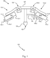
- Figure 1 illustrates a top view of a machine 100.
- the machine 100 includes a take-off apparatus for unwinding strands of material from wound packages, by using rotatable arms. It is contemplated that either or both of the rotatable arms of Figure 1 can be the rotatable arms described in US patent application entitled " Apparatus with Rotatable Arm for Unwinding Strands of Material” filed on November 4, 2011 by The Procter & Gamble Company and published as WO2013/067114 .
- the machine 100 also includes a splicing apparatus for routing strands of material as the strands are transferred from an active package to a standby package, during an unwinding process.
- the take-off apparatus includes a first package unwind station 110-1 and a second package unwind station 110-2, mounted to a frame 105.
- the first package unwind station 110-1 includes a first holder 111-1 for holding a package
- the second package unwind station 110-2 includes a second holder 111-2 for holding a package.
- a first package 112-1 is loaded into the first package unwind station 110-1.
- the first package 112-1 includes a strand of material wound onto a cylindrical core.
- the first package 112-1 also has an overall shape that is cylindrical, with substantially flat ends and a side 116-1, which is the curved surface around the circumference of the cylindrical shape.
- the front end of the first package 112-1 is angled toward a downstream infeed location 109.
- a first rotating arm 119-1 is configured to unwind a strand from the first package 112-1 to the downstream infeed location 109.
- a second package 112-2 is loaded into the second package unwind station 110-2.
- the second package 112-2 includes a strand of material wound onto a cylindrical core.
- the second package 112-2 also has an overall shape that is cylindrical, with substantially flat ends and a side 116-2, which is the curved surface around the circumference of the cylindrical shape.
- the front end of the second package 112-2 is angled toward the downstream infeed location 109.
- a second rotating arm 119-2 is configured to unwind a strand from the second package 112-2 to the downstream infeed location 109.
- the splicing apparatus includes a first collapsible splice trigger 120-1, a splice wrap housing 130, a second splice trigger 120-2, and a holding arm 141.
- the collapsible splice triggers 120-1 and 120-2 and the splice wrap housing 130 are described below.
- the splice wrap housing 130 has a contact surface 132.
- the splice wrap housing 130 can be made from various solid materials that are rigid and sturdy.
- the splice wrap housing 130 can be made from plastic, metal, ceramic, wood, etc.
- the contact surface 132 can be made from various solid materials that are hard.
- the strand guides can be made from plastic, metal, ceramic, etc.
- a magnet 144 is mounted to the distal end of the holding arm 144.
- the magnet 144 attracts a piece of ferrous material 145-2 attached to the distal end of the second rotatable arm 119-2.
- the holding arm 144 is swung toward the second package unwind station 110-2.
- the holding arm 144 can hold the second rotatable arm 119-2 in a predetermined position, by using magnetic force.
- a piece of ferrous material 145-1 is also attached to the distal end of the first rotatable arm 119-1.
- the holding arm 144 can also be swung toward the first package unwind station 110-1, to hold the first rotatable arm 119-1 in a predetermined position.
- FIG 2 illustrates an isometric view of the first collapsible splice trigger 120-1 used in the splicing apparatus of Figure 1 .
- the collapsible splice trigger 120-1 is in its upright (vertical) position.
- the splice trigger 120-1 includes a body 121-1 and a pin.
- the body 121-1 has a slot 125-1 and the pin is set in the slot 125-1.
- the pin has a first contact surface 122-1 and a cap 124-1.
- the collapsible splice trigger 120-1 is configured to collapse when a predetermined force (based on the desired strand tension during splicing and based on the breaking strength of the strand) pulls the pin forward in the slot 125-1.
- the pin When the collapsible splice trigger 120-1 collapses, the pin is configured to move in the slot 125-1 by rotating 127-1 around an axis 126-1, to a collapsed (horizontal) position 129-1. In the collapsed position 129-1, the pin points in a first collapse direction 128-1. Once collapsed the collapsible splice trigger 120-1 can be reset to its upright position.
- the collapsible splice trigger 120-1 can be made from various solid materials that are rigid and sturdy.
- the collapsible splice trigger 120-1 can be made from plastic, metal, ceramic, wood, etc.
- the first contact surface 122-1 can be made from various solid materials that are hard.
- the strand guides can be made from plastic, metal, ceramic, etc.
- the collapsible splice trigger 120-1 can be configured with a spring to collapse at the predetermined force.
- the second collapsible splice trigger 120-2 can be configured in the same way as the first collapsible splice trigger 120-1.
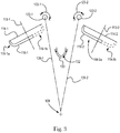
- Figure 3 illustrates a top view of portions of the splicing apparatus of Figure 1 .
- Figure 3 shows the first rotatable arm 119-1 of Figure 1 in a first position 119-1a, and rotated around a first rotational axis 113-1 to an alternate position 119-1b.
- the first rotatable arm 119-1 is an unpowered arm.
- the first rotatable arm 119-1 is configured to unwind a strand from the first package 112-1 of Figure 1 to the downstream infeed location 109.
- the first rotatable arm 119-1 includes a first strand guide, and the rotation of the first rotatable arm 119-1 around the first rotational axis 113-1 defines a first circular path 114-1 for a distal end of the first strand guide.
- Figure 3 also shows the contact surface 122-1 of the first collapsible splice trigger 120-1 with a wrap angle 123-1 formed by the portion of the first contact surface 122-1 that is contacted by a strand routed through the splicing apparatus.
- the first collapsible splice trigger 120-1 has a first collapse direction 128-1, which points substantially toward the downstream infeed location 109.
- the word substantially when the word substantially is applied to directions, the word substantially means within 0-30° (or any integer value within this range) of the specified direction.
- Figure 3 further shows the contact surface 132 of the splice wrap housing 130 with a wrap angle 133 formed by the portion of the contact surface 132 that is contacted by a strand routed through the splicing apparatus.
- the wrap angle 133 can be between 275 and 315 degrees.
- Figure 3 shows the contact surface 122-2 of the second collapsible splice trigger 120-2 with a wrap angle 123-2 formed by the portion of the second contact surface 122-2 that is contacted by a strand routed through the splicing apparatus.
- the second collapsible splice trigger 120-2 has a second collapse direction 128-2, which points substantially toward the downstream infeed location 109.
- Figure 3 also shows the second rotatable arm 119-2 of Figure 1 in a second position 119-2a, and rotated around a second rotational axis 113-2 to an alternate position 119-2b.
- the second rotatable arm 119-2 is an unpowered arm.
- the second rotatable arm 119-2 is configured to unwind a strand from the second package 112-2 of Figure 1 to the downstream infeed location 109.
- the second rotatable arm 119-2 includes a second strand guide, and the rotation of the second rotatable arm 119-2 around the second rotational axis 113-2 defines a second circular path 114-2 for a distal end of the second strand guide.
- Figure 4A illustrates a top view of the circumferential spacing of elements of the splicing apparatus of Figure 3 .
- a circumferential location refers to the relative locations of elements, with respect to reference lines radiating out from the downstream infeed location 109. For example, if a first reference line radiates out from the downstream infeed location, and a second reference line radiates out from the downstream infeed location, and a reference point exists in the sector that is bounded by the first and second reference lines, then the reference point is disposed circumferentially between the first and second reference lines.
- radial spacing 170 refers to locations of elements in terms of distance from the downstream infeed location 109, with 171 referring to radially inboard (relatively closer to the downstream infeed location 109) and 171 referring to radially outboard 179 (relatively farther the downstream infeed location 109).
- Figure 4A includes reference lines 151, 152, 153, and 154, which define boundaries for sectors are 161, 162, 163, 164, and 165.
- Reference line 151 extends from the downstream infeed location 109 through a radially farthest point 115-1b on the first circular path 114-1.
- Reference line 151 defines one side of the sector 161.
- Reference line 152 extends from the downstream infeed location 109 through a circumferentially farthest point 135-1 on one side of the contact surface 132 of the splice wrap housing 130.
- Reference lines 151 and 152 define the sides of the sector 162.
- Reference line 153 extends from the downstream infeed location 109 through a circumferentially farthest point 135-2 on the other side of the contact surface 132 of the splice wrap housing 130.
- Reference lines 152 and 153 define the sides of the sector 163.
- Reference line 154 extends from the downstream infeed location 109 through a radially farthest point 115-2b on the second circular path 114-2.
- Reference line 154 defines one side of the sector 165.
- the first circular path 114-1 is disposed in sector 161
- the first collapsible splice trigger 120-1 is disposed in sector 162
- the splice wrap housing 130 is disposed in sector 163
- the second collapsible splice trigger 120-2 is disposed in sector 164
- the second circular path 114-2 is disposed in sector 165.
- Figure 4B illustrates a top view of the radial spacing of elements of the splicing apparatus of Figure 3 .
- the first circular path 114-1 has the farthest point 115-1b that is farthest radially outboard 179 from the downstream infeed location 109, as measured by the distance 181.
- the first collapsible splice trigger 120-1 has a farthest point 122-1b on the first contact surface 122-1 that is farthest radially outboard 179 from the downstream infeed location 109, as measured by the distance 182.
- the splice wrap housing 130 has a nearest point 132-1a on the strand contact surface 132 that is closest radially inboard 171 to the downstream infeed location 109, as measured by the distance 183.
- the second collapsible splice trigger 120-2 has a farthest point 122-2b on the second contact surface 122-1 that is farthest radially outboard 179 from the downstream infeed location 109, as measured by the distance 184.
- the second circular path 114-2 has the farthest point 115-2b that is farthest radially outboard 179 from the downstream infeed location 109, as measured by the distance 185.
- Distance 182 is greater than distance 181 and distance 183.
- distance 181 is greater than distance 183, although in various embodiments this is not required.
- Distance 184 is greater than distance 183 and distance 185.
- distance 185 is greater than distance 183, although in various embodiments this is not required.
- distance 181 is equal to distance 185, and distance 182 is equal to distance 184, although in various embodiments these relationships are not required.
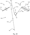
- Figure 5A illustrates a top view of a joined strand threaded up in the splicing apparatus of Figure 1 , with the first package 112-1 in the first unwind station 110-1 as the active package and the second package 112-2 in the second unwind station 110-2 as the standby package.
- the first package 112-1 has a first strand and the second package 112-2 has a second strand.
- a trailing end of the first strand is joined to a leading end of the second strand, to form a joined strand.
- the joined strand is routed with an active package strand routing 190-a that has a number of routing legs.
- each of the routing legs is shown as substantially linear, however in various embodiments this is not required.
- the strand routing 190-a includes a first routing leg 191-a from the downstream infeed location 109 to the first strand guide of the first rotating arm on the first circular path 114-1. From the trailing end of the first strand (disposed near a core of the first package 112-1), the joined strand is disposed around the first contact surface 122-1 of the first collapsible splice trigger 120-1, forming a second routing leg 192-a.
- the joined strand is also disposed around the contact surface 132 of the splice wrap housing 130, forming a third routing leg 193-a. From the contact surface 132 of the splice wrap housing 130, the joined strand is further disposed on the second strand guide of the second rotating arm on the second circular path 114-2, forming a fourth routing leg 194-a. As the joined strand is unwound and transferred from the active first package 112-1 to the standby second package 112-2, the strand follows the strand routing 190-a, which then changes, as part of the splicing, as described below.
- Figure 5B illustrates a top view of the joined strand of Figure 5A , with a splicing strand routing 190-b, as the joined strand is being transferred from the formerly active package in the first package unwind station 110-1 to the standby package in the second package unwind station 110-2
- the joined strand is pulled off of the strand guide of the first rotatable arm, and off of the core in the first unwind station 110-1; then tension in the joined strand pulls the joined strand toward the downstream infeed location 109.
- Tension in the strand pulls the pin of the first collapsible splice trigger 120-1 in the collapse direction, which is toward the downstream infeed location 109.
- the tension creates a pulling force that reaches the predetermined force for the first collapsible splice trigger 120-1
- the first collapsible splice trigger 120-1 collapses.
- Tension in the joined strand again pulls the joined strand toward the downstream infeed location 109, and the joined strand is unwrapped from the contact surface 132 of the splice wrap housing 130. This eliminates the second routing leg 192-b and the third routing leg 193-a.
- the joined strand is transferred to the standby package, which is the second package 112-2.
- Figure 5C illustrates a top view of the joined strand of Figure 5B , with a standby package strand routing 190-c, after the joined strand is transferred to the second package 112-2.
- this creates a new fourth routing leg 194-c, from the downstream infeed location 109 to the second strand guide of the second rotating arm on the second circular path 114-2.
- the second package 112-2 which was formerly the standby package, becomes the new active package.
- the core from the first package 112-1 can be removed and a new standby package 112-3 can be added to the first package unwind station 110-1 as the new standby package.
- the second package 112-2 has a second strand and the third package 112-3 has a third strand. A trailing end of the second strand is joined to a leading end of the third strand, to form a newly joined strand.
- the newly joined strand is routed with an new active package strand routing 190-d that has a number of routing legs.
- the strand routing 190-d includes the fourth routing leg 194-c from the downstream infeed location 109 to the second strand guide of the second rotating arm on the second circular path 114-2. From the trailing end of the second strand (disposed near a core of the second package 112-2), the newly joined strand is disposed around the second contact surface 122-2 of the second collapsible splice trigger 120-2, forming a fifth routing leg 195-d. From second contact surface 122-2, the newly joined strand is also disposed around the contact surface 132 of the splice wrap housing 130, forming a sixth routing leg 196-d.
- the newly joined strand is further disposed on the first strand guide of the first rotating arm on the first circular path 114-1, forming a seventh routing leg 197-d.
- the strand follows the strand routing 190-d, which then changes, as part of the splicing.
- the splicing is performed from the second package unwind station 110-2 to the first package unwind station 110-1 in the same manner as taught for splicing from the first package unwind station 110-1 to the second package unwind station 110-2, as described above.
- Embodiments of the present disclosure use a splicing apparatus to properly route strands of material as the strands are transferred from active packages to standby packages, during the unwinding process.
- Using the splicing apparatus enables the strand to maintain a proper orientation with respect to the packages, strand guides, and downstream equipment. This is especially useful for processes that unwind strands with rotatable arms. As a result, take off equipment can unwind packages in sequence while continuously feeding the downstream equipment.
Landscapes
- Replacement Of Web Rolls (AREA)
- Unwinding Of Filamentary Materials (AREA)
- Spinning Or Twisting Of Yarns (AREA)
- Treatment Of Fiber Materials (AREA)
Description
- The present disclosure relates to an apparatus for unwinding strands of material from wound packages. In particular, the present disclosure relates to a splicing apparatus for continuously unwinding strands of material from wound packages.
- Take off equipment is used to unwind strands of material that have been pre-wound onto cores. The pre-wound cores are called packages. Take off equipment unwinds a strand and then feeds the unwound strand to downstream equipment. Take off equipment can unwind packages in sequence while continuously feeding the downstream equipment. Each package has a single continuous strand of material with a leading end and a trailing end. In a take off process, the trailing end of a first package can be joined to the leading end of second package.
- As take off equipment finishes unwinding the first (active) package, it pulls off the trailing end, which pulls off the leading end of the second (standby) package, which begins the unwinding of the second package. The standby package becomes the new active package. The finished first package can be replaced with a new standby package. This process of connecting ends and replacing packages can be repeated indefinitely. Thus, in a take off process, there is no need to stop the downstream equipment to replace packages.
- One type of take-off equipment uses rotating arms. Each arm has one or more strand guides to direct the strand. For this type of take-off equipment, to transfer the unwinding from an active package to a standby package at line speed, the strand must be properly routed to enable the strand to maintain a proper orientation with respect to the packages, the strand guides, and the downstream equipment.
- Take-off equipment that uses rotating arms is known from
US 1,578,488 . In this take-off equipment the strand is routed through a clip.US 4,298,174 andWO 2004/069712 disclose collapsible splice triggers. - Embodiments of the present disclosure use a splicing apparatus to properly route strands of material as the strands are transferred from active packages to standby packages, during the unwinding process. Using the splicing apparatus enables the strand to maintain a proper orientation with respect to the packages, strand guides, and downstream equipment. This is especially useful for processes that unwind strands with rotatable arms. As a result, take off equipment can unwind packages in sequence while continuously feeding the downstream equipment.
- The invention is set out in Claim 1.
-
-
Figure 1 illustrates a top view of a machine with a splicing apparatus for routing strands of material as the strands are transferred from an active package to a standby package, during an unwinding process that uses rotatable arms. -
Figure 2 illustrates an isometric view of a splice trigger used in the splicing apparatus ofFigure 1 . -
Figure 3 illustrates a top view of portions of the splicing apparatus ofFigure 1 . -
Figure 4A illustrates a top view of the circumferential spacing of elements of the splicing apparatus ofFigure 3 . -
Figure 4B illustrates a top view of the radial spacing of elements of the splicing apparatus ofFigure 3 . -
Figure 5A illustrates a top view of a joined strand threaded up in the splicing apparatus ofFigure 1 . -
Figure 5B illustrates a top view of the joined strand ofFigure 5A , as the joined strand is being transferred from an active package to a standby package. -
Figure 5C illustrates a top view of the joined strand ofFigure 5B , after the joined strand is transferred to the standby package. -
Figure 5D illustrates a top view of the strand ofFigure 5C , joined to a new standby package. - Embodiments of the present disclosure use a splicing apparatus to properly route strands of material as the strands are transferred from active packages to standby packages, during the unwinding process. Using the splicing apparatus enables the strand to maintain a proper orientation with respect to the packages, strand guides, and downstream equipment. This is especially useful for processes that unwind strands with rotatable arms. As a result, take off equipment can unwind packages in sequence while continuously feeding the downstream equipment.
- Embodiments of the present disclosure can be used with all kinds of strands (and bands), of various sizes and shapes, made from different materials. For example, embodiments of the present disclosure can be used to unwind string, elastic, metal wire, etc.
-
Figure 1 illustrates a top view of amachine 100. Themachine 100 includes a take-off apparatus for unwinding strands of material from wound packages, by using rotatable arms. It is contemplated that either or both of the rotatable arms ofFigure 1 can be the rotatable arms described in US patent application entitled "Apparatus with Rotatable Arm for Unwinding Strands of Material" filed on November 4, 2011 by The Procter & Gamble Company and published asWO2013/067114 . - The
machine 100 also includes a splicing apparatus for routing strands of material as the strands are transferred from an active package to a standby package, during an unwinding process. - The take-off apparatus includes a first package unwind station 110-1 and a second package unwind station 110-2, mounted to a
frame 105. The first package unwind station 110-1 includes a first holder 111-1 for holding a package, and the second package unwind station 110-2 includes a second holder 111-2 for holding a package. - In
Figure 1 , a first package 112-1 is loaded into the first package unwind station 110-1. The first package 112-1 includes a strand of material wound onto a cylindrical core. The first package 112-1 also has an overall shape that is cylindrical, with substantially flat ends and a side 116-1, which is the curved surface around the circumference of the cylindrical shape. The front end of the first package 112-1 is angled toward adownstream infeed location 109. A first rotating arm 119-1 is configured to unwind a strand from the first package 112-1 to thedownstream infeed location 109. - Also, in
Figure 1 , a second package 112-2 is loaded into the second package unwind station 110-2. The second package 112-2 includes a strand of material wound onto a cylindrical core. The second package 112-2 also has an overall shape that is cylindrical, with substantially flat ends and a side 116-2, which is the curved surface around the circumference of the cylindrical shape. The front end of the second package 112-2 is angled toward thedownstream infeed location 109. A second rotating arm 119-2 is configured to unwind a strand from the second package 112-2 to thedownstream infeed location 109. - The splicing apparatus includes a first collapsible splice trigger 120-1, a
splice wrap housing 130, a second splice trigger 120-2, and a holdingarm 141. The collapsible splice triggers 120-1 and 120-2 and the splice wraphousing 130 are described below. - The splice wrap
housing 130 has acontact surface 132. The splice wraphousing 130 can be made from various solid materials that are rigid and sturdy. For example, the splice wraphousing 130 can be made from plastic, metal, ceramic, wood, etc. Thecontact surface 132 can be made from various solid materials that are hard. For example, the strand guides can be made from plastic, metal, ceramic, etc. - A
magnet 144 is mounted to the distal end of the holdingarm 144. Themagnet 144 attracts a piece of ferrous material 145-2 attached to the distal end of the second rotatable arm 119-2. The holdingarm 144 is swung toward the second package unwind station 110-2. Thus, the holdingarm 144 can hold the second rotatable arm 119-2 in a predetermined position, by using magnetic force. A piece of ferrous material 145-1 is also attached to the distal end of the first rotatable arm 119-1. The holdingarm 144 can also be swung toward the first package unwind station 110-1, to hold the first rotatable arm 119-1 in a predetermined position. -
Figure 2 illustrates an isometric view of the first collapsible splice trigger 120-1 used in the splicing apparatus ofFigure 1 . InFigure 2B , the collapsible splice trigger 120-1 is in its upright (vertical) position. The splice trigger 120-1 includes a body 121-1 and a pin. The body 121-1 has a slot 125-1 and the pin is set in the slot 125-1. The pin has a first contact surface 122-1 and a cap 124-1. The collapsible splice trigger 120-1 is configured to collapse when a predetermined force (based on the desired strand tension during splicing and based on the breaking strength of the strand) pulls the pin forward in the slot 125-1. When the collapsible splice trigger 120-1 collapses, the pin is configured to move in the slot 125-1 by rotating 127-1 around an axis 126-1, to a collapsed (horizontal) position 129-1. In the collapsed position 129-1, the pin points in a first collapse direction 128-1. Once collapsed the collapsible splice trigger 120-1 can be reset to its upright position. - The collapsible splice trigger 120-1 can be made from various solid materials that are rigid and sturdy. For example, the collapsible splice trigger 120-1 can be made from plastic, metal, ceramic, wood, etc. The first contact surface 122-1 can be made from various solid materials that are hard. For example, the strand guides can be made from plastic, metal, ceramic, etc. The collapsible splice trigger 120-1 can be configured with a spring to collapse at the predetermined force. The second collapsible splice trigger 120-2 can be configured in the same way as the first collapsible splice trigger 120-1.
-
Figure 3 illustrates a top view of portions of the splicing apparatus ofFigure 1 .Figure 3 shows the first rotatable arm 119-1 ofFigure 1 in a first position 119-1a, and rotated around a first rotational axis 113-1 to an alternate position 119-1b. InFigure 3 , the first rotatable arm 119-1 is an unpowered arm. The first rotatable arm 119-1 is configured to unwind a strand from the first package 112-1 ofFigure 1 to thedownstream infeed location 109. The first rotatable arm 119-1 includes a first strand guide, and the rotation of the first rotatable arm 119-1 around the first rotational axis 113-1 defines a first circular path 114-1 for a distal end of the first strand guide. -
Figure 3 also shows the contact surface 122-1 of the first collapsible splice trigger 120-1 with a wrap angle 123-1 formed by the portion of the first contact surface 122-1 that is contacted by a strand routed through the splicing apparatus. The first collapsible splice trigger 120-1 has a first collapse direction 128-1, which points substantially toward thedownstream infeed location 109. As used herein, when the word substantially is applied to directions, the word substantially means within 0-30° (or any integer value within this range) of the specified direction. -
Figure 3 further shows thecontact surface 132 of the splice wraphousing 130 with awrap angle 133 formed by the portion of thecontact surface 132 that is contacted by a strand routed through the splicing apparatus. Thewrap angle 133 can be between 275 and 315 degrees. -
Figure 3 shows the contact surface 122-2 of the second collapsible splice trigger 120-2 with a wrap angle 123-2 formed by the portion of the second contact surface 122-2 that is contacted by a strand routed through the splicing apparatus. The second collapsible splice trigger 120-2 has a second collapse direction 128-2, which points substantially toward thedownstream infeed location 109. -
Figure 3 also shows the second rotatable arm 119-2 ofFigure 1 in a second position 119-2a, and rotated around a second rotational axis 113-2 to an alternate position 119-2b. InFigure 3 , the second rotatable arm 119-2 is an unpowered arm. The second rotatable arm 119-2 is configured to unwind a strand from the second package 112-2 ofFigure 1 to thedownstream infeed location 109. The second rotatable arm 119-2 includes a second strand guide, and the rotation of the second rotatable arm 119-2 around the second rotational axis 113-2 defines a second circular path 114-2 for a distal end of the second strand guide. -
Figure 4A illustrates a top view of the circumferential spacing of elements of the splicing apparatus ofFigure 3 . Throughout the present disclosure, a circumferential location refers to the relative locations of elements, with respect to reference lines radiating out from thedownstream infeed location 109. For example, if a first reference line radiates out from the downstream infeed location, and a second reference line radiates out from the downstream infeed location, and a reference point exists in the sector that is bounded by the first and second reference lines, then the reference point is disposed circumferentially between the first and second reference lines. Also, throughout the present disclosure,radial spacing 170 refers to locations of elements in terms of distance from thedownstream infeed location 109, with 171 referring to radially inboard (relatively closer to the downstream infeed location 109) and 171 referring to radially outboard 179 (relatively farther the downstream infeed location 109). -
Figure 4A includesreference lines Reference line 151 extends from thedownstream infeed location 109 through a radially farthest point 115-1b on the first circular path 114-1.Reference line 151 defines one side of thesector 161.Reference line 152 extends from thedownstream infeed location 109 through a circumferentially farthest point 135-1 on one side of thecontact surface 132 of the splice wraphousing 130.Reference lines sector 162.Reference line 153 extends from thedownstream infeed location 109 through a circumferentially farthest point 135-2 on the other side of thecontact surface 132 of the splice wraphousing 130.Reference lines sector 163.Reference line 154 extends from thedownstream infeed location 109 through a radially farthest point 115-2b on the second circular path 114-2.Reference line 154 defines one side of thesector 165. - In
Figure 4A , the first circular path 114-1 is disposed insector 161, the first collapsible splice trigger 120-1 is disposed insector 162, the splice wraphousing 130 is disposed insector 163, the second collapsible splice trigger 120-2 is disposed insector 164, and the second circular path 114-2 is disposed insector 165. -
Figure 4B illustrates a top view of the radial spacing of elements of the splicing apparatus ofFigure 3 . The first circular path 114-1 has the farthest point 115-1b that is farthest radially outboard 179 from thedownstream infeed location 109, as measured by thedistance 181. The first collapsible splice trigger 120-1 has a farthest point 122-1b on the first contact surface 122-1 that is farthest radially outboard 179 from thedownstream infeed location 109, as measured by thedistance 182. The splice wraphousing 130 has a nearest point 132-1a on thestrand contact surface 132 that is closest radially inboard 171 to thedownstream infeed location 109, as measured by thedistance 183. The second collapsible splice trigger 120-2 has a farthest point 122-2b on the second contact surface 122-1 that is farthest radially outboard 179 from thedownstream infeed location 109, as measured by thedistance 184. The second circular path 114-2 has the farthest point 115-2b that is farthest radially outboard 179 from thedownstream infeed location 109, as measured by thedistance 185. -
Distance 182 is greater thandistance 181 anddistance 183. InFigure 4B ,distance 181 is greater thandistance 183, although in various embodiments this is not required.Distance 184 is greater thandistance 183 anddistance 185. InFigure 4B ,distance 185 is greater thandistance 183, although in various embodiments this is not required. InFigure 4B ,distance 181 is equal todistance 185, anddistance 182 is equal todistance 184, although in various embodiments these relationships are not required. -
Figure 5A illustrates a top view of a joined strand threaded up in the splicing apparatus ofFigure 1 , with the first package 112-1 in the first unwind station 110-1 as the active package and the second package 112-2 in the second unwind station 110-2 as the standby package. The first package 112-1 has a first strand and the second package 112-2 has a second strand. A trailing end of the first strand is joined to a leading end of the second strand, to form a joined strand. - The joined strand is routed with an active package strand routing 190-a that has a number of routing legs. In the embodiments of
Figures 5A-5D , each of the routing legs is shown as substantially linear, however in various embodiments this is not required. The strand routing 190-a includes a first routing leg 191-a from thedownstream infeed location 109 to the first strand guide of the first rotating arm on the first circular path 114-1. From the trailing end of the first strand (disposed near a core of the first package 112-1), the joined strand is disposed around the first contact surface 122-1 of the first collapsible splice trigger 120-1, forming a second routing leg 192-a. From first contact surface 122-1, the joined strand is also disposed around thecontact surface 132 of the splice wraphousing 130, forming a third routing leg 193-a. From thecontact surface 132 of the splice wraphousing 130, the joined strand is further disposed on the second strand guide of the second rotating arm on the second circular path 114-2, forming a fourth routing leg 194-a. As the joined strand is unwound and transferred from the active first package 112-1 to the standby second package 112-2, the strand follows the strand routing 190-a, which then changes, as part of the splicing, as described below. -
Figure 5B illustrates a top view of the joined strand ofFigure 5A , with a splicing strand routing 190-b, as the joined strand is being transferred from the formerly active package in the first package unwind station 110-1 to the standby package in the second package unwind station 110-2 After the active package is fully unwound (leaving a core in the first unwind station 110-1), the joined strand is pulled off of the strand guide of the first rotatable arm, and off of the core in the first unwind station 110-1; then tension in the joined strand pulls the joined strand toward thedownstream infeed location 109. This eliminates the first routing leg 191-a and creates a new second routing leg 192-b, from the first contact surface 122-1 of the first collapsible splice trigger 120-1 to thedownstream infeed location 109. - Tension in the strand pulls the pin of the first collapsible splice trigger 120-1 in the collapse direction, which is toward the
downstream infeed location 109. When the tension creates a pulling force that reaches the predetermined force for the first collapsible splice trigger 120-1, the first collapsible splice trigger 120-1 collapses. Tension in the joined strand again pulls the joined strand toward thedownstream infeed location 109, and the joined strand is unwrapped from thecontact surface 132 of the splice wraphousing 130. This eliminates the second routing leg 192-b and the third routing leg 193-a. The joined strand is transferred to the standby package, which is the second package 112-2. -
Figure 5C illustrates a top view of the joined strand ofFigure 5B , with a standby package strand routing 190-c, after the joined strand is transferred to the second package 112-2. When the joined strand is transferred to the second package 112-2, this creates a new fourth routing leg 194-c, from thedownstream infeed location 109 to the second strand guide of the second rotating arm on the second circular path 114-2. The second package 112-2, which was formerly the standby package, becomes the new active package. - As shown in
Figure 5D , once the second package 112-2 becomes the new active package, the core from the first package 112-1 can be removed and a new standby package 112-3 can be added to the first package unwind station 110-1 as the new standby package. The second package 112-2 has a second strand and the third package 112-3 has a third strand. A trailing end of the second strand is joined to a leading end of the third strand, to form a newly joined strand. - The newly joined strand is routed with an new active package strand routing 190-d that has a number of routing legs. The strand routing 190-d includes the fourth routing leg 194-c from the
downstream infeed location 109 to the second strand guide of the second rotating arm on the second circular path 114-2. From the trailing end of the second strand (disposed near a core of the second package 112-2), the newly joined strand is disposed around the second contact surface 122-2 of the second collapsible splice trigger 120-2, forming a fifth routing leg 195-d. From second contact surface 122-2, the newly joined strand is also disposed around thecontact surface 132 of the splice wraphousing 130, forming a sixth routing leg 196-d. From thecontact surface 132 of the splice wraphousing 130, the newly joined strand is further disposed on the first strand guide of the first rotating arm on the first circular path 114-1, forming a seventh routing leg 197-d. As the newly joined strand is unwound and transferred from the new active second package 112-2 to the new standby third package 112-3, the strand follows the strand routing 190-d, which then changes, as part of the splicing. The splicing is performed from the second package unwind station 110-2 to the first package unwind station 110-1 in the same manner as taught for splicing from the first package unwind station 110-1 to the second package unwind station 110-2, as described above. - Embodiments of the present disclosure use a splicing apparatus to properly route strands of material as the strands are transferred from active packages to standby packages, during the unwinding process. Using the splicing apparatus enables the strand to maintain a proper orientation with respect to the packages, strand guides, and downstream equipment. This is especially useful for processes that unwind strands with rotatable arms. As a result, take off equipment can unwind packages in sequence while continuously feeding the downstream equipment.
- The dimensions and values disclosed herein are not to be understood as being strictly limited to the exact numerical values recited. Instead, unless otherwise specified, each such dimension is intended to mean both the recited value and a functionally equivalent range surrounding that value. For example, a dimension disclosed as "40 mm" is intended to mean "about 40 mm."
- While particular embodiments of the present invention have been illustrated and described, it would be obvious to those skilled in the art that various other changes and modifications can be made without departing from the scope of the invention. It is therefore intended to cover in the appended claims all such changes and modifications that are within the scope of this invention.
Claims (6)
- A machine for unwinding a strand of material, the machine comprising:a first package unwind station (110-1), configured to unwind a strand from a first package loaded (112-1) into the first package unwind station (110-1) to a downstream infeed location (109), wherein the first package unwind station (110-1) includes a first apparatus with a first unpowered rotatable arm (119-1) that includes a first rotational axis (113-1) and a first strand guide , wherein rotation of the first rotatable arm (119-1) around the first rotational axis (113-1) defines a first circular path for a distal end of the first strand guide;a second package unwind station (110-2), configured to unwind a strand from a second package (112-2) loaded into the second package unwind station (110-2) to the downstream infeed location (109), wherein the second package unwind station includes a second apparatus with a second unpowered rotatable arm (119-2) that includes a second rotational axis (113-2) and a second strand guide, wherein rotation of the second rotatable arm (119-2) around the second rotational axis (113-2) defines a second circular path for a distal end of the second strand guide; anda first collapsible splice trigger (120-1) with a first strand contact surface (122-1), wherein the first collapsible splice trigger is disposed circumferentially between the first rotational axis (113-1) and the second rotational axis (113-2)characterized in that the machine further comprises a splice wrap housing (130), wherein the splice wrap housing is disposed circumferentially between the first collapsible splice trigger (120-1) and the second circular path,
wherein disposed circumferentially means with respect to reference lines radiating out from the downstream infeed location (109);wherein the splice wrap housing (130) has a splice wrap strand contact surface (132) with a splice wrap contact surface nearest point that is radially nearest to the downstream infeed location (109);
the splice wrap contact surface nearest point is radially nearer to the downstream infeed location (109) than the first strand contact surface farthest point;wherein the second circular path has a second circular path farthest point that is radially farthest from the downstream infeed location (109); andthe second circular path farthest point is radially farther from the downstream infeed location than the splice wrap contact surface nearest point. - The machine according to claim 1, wherein the first collapsible splice trigger (120-1) has a first collapse direction, and the first collapsible splice trigger is disposed on the machine such that the first collapse direction is oriented substantially toward the downstream infeed location (109).
- The machine of claim 2, wherein the first collapse direction is oriented completely toward the downstream infeed location (109).
- The machine of claim 1, wherein the first collapsible splice trigger (120-1) is disposed between the first circular path and the second rotational axis.
- The machine of claim 4, wherein the first collapsible splice trigger (120-1) is disposed between the first circular path and the second circular path.
- The machine according to any of claims 1,4 or 5, wherein:the first circular path has a first circular path farthest point that is radially farthest from the downstream infeed location (109);the first strand contact surface has a first strand contact surface farthest point that is radially farthest from the downstream infeed location (109); andthe first strand contact surface farthest point is radially farther from the downstream infeed location (109) than the first circular path farthest point.
Applications Claiming Priority (2)
| Application Number | Priority Date | Filing Date | Title |
|---|---|---|---|
| US13/289,207 US9051151B2 (en) | 2011-11-04 | 2011-11-04 | Splicing apparatus for unwinding strands of material |
| PCT/US2012/062961 WO2013067115A1 (en) | 2011-11-04 | 2012-11-01 | Splicing apparatus for unwinding strands of material |
Publications (2)
| Publication Number | Publication Date |
|---|---|
| EP2773581A1 EP2773581A1 (en) | 2014-09-10 |
| EP2773581B1 true EP2773581B1 (en) | 2017-01-04 |
Family
ID=47291230
Family Applications (1)
| Application Number | Title | Priority Date | Filing Date |
|---|---|---|---|
| EP12795664.7A Active EP2773581B1 (en) | 2011-11-04 | 2012-11-01 | Splicing apparatus for unwinding strands of material |
Country Status (7)
| Country | Link |
|---|---|
| US (1) | US9051151B2 (en) |
| EP (1) | EP2773581B1 (en) |
| JP (1) | JP2014532606A (en) |
| CN (1) | CN103906694A (en) |
| BR (1) | BR112014010285A2 (en) |
| CA (1) | CA2854156A1 (en) |
| WO (1) | WO2013067115A1 (en) |
Families Citing this family (2)
| Publication number | Priority date | Publication date | Assignee | Title |
|---|---|---|---|---|
| CN106102674A (en) | 2014-03-17 | 2016-11-09 | 宝洁公司 | Apparatus and method for manufacturing absorbent articles |
| CN116240741B (en) * | 2023-05-11 | 2023-08-01 | 江苏长海消防装备有限公司 | Twisting device for producing fire-fighting safety rope |
Citations (1)
| Publication number | Priority date | Publication date | Assignee | Title |
|---|---|---|---|---|
| WO2004069712A1 (en) * | 2003-02-05 | 2004-08-19 | Saurer Gmbh & Co. Kg | Thread take-off device |
Family Cites Families (67)
| Publication number | Priority date | Publication date | Assignee | Title |
|---|---|---|---|---|
| US1459694A (en) | 1923-06-19 | |||
| US1578488A (en) | 1923-05-08 | 1926-03-30 | Western Electric Co | Apparatus for handling strands |
| US1547596A (en) | 1925-01-05 | 1925-07-28 | Warp Compressing Machine Compa | Creel or spool stand |
| US2021032A (en) | 1933-04-28 | 1935-11-12 | Universal Winding Co | Yarn controller for creels and like apparatus |
| CH223815A (en) | 1940-04-06 | 1942-10-15 | Comp Generale Electricite | Device for unwinding a very long object wound on a reel. |
| GB598999A (en) | 1944-09-19 | 1948-03-02 | British Celanese | Improvements in yarn-winding machines |
| US2602606A (en) | 1946-10-30 | 1952-07-08 | American Viscose Corp | Flyer for unwinding cakes and other packages |
| US2809791A (en) | 1955-01-10 | 1957-10-15 | Belden Mfg Co | Continuous dead reel let-off with controlled tension |
| US2851228A (en) | 1955-04-29 | 1958-09-09 | Western Electric Co | Dereeling device |
| US2942802A (en) | 1955-08-30 | 1960-06-28 | Western Electric Co | Transfer device for guiding strand as it is continuously unwound from spools |
| US3073545A (en) | 1958-11-10 | 1963-01-15 | Western Electric Co | Apparatus for unwinding strands |
| US3150845A (en) * | 1959-11-28 | 1964-09-29 | American Enka Corp | Magazine creel |
| FR1321597A (en) * | 1962-02-09 | 1963-03-22 | Verre Textile Soc Du | Further training in winding devices |
| US3175784A (en) * | 1962-11-13 | 1965-03-30 | Western Electric Co | Filament guide |
| US3315917A (en) | 1964-08-24 | 1967-04-25 | Ivan S Brown | Cable laying device |
| GB1090928A (en) * | 1965-07-16 | 1967-11-15 | Ici Ltd | Improvements in or relating to unwinding yarn from packages arrayed in series |
| SE328452B (en) | 1969-03-05 | 1970-09-14 | Winkler Fallert & Co Maschf | |
| DE7030250U (en) | 1970-08-12 | 1971-04-22 | Glanzstoff Ag | WIND ARM FOR PULLING STRONG GUNT, ESPECIALLY WIRE. |
| IT1038150B (en) * | 1974-06-28 | 1979-11-20 | Fujikura Ltd | METHOD AND EQUIPMENT FOR CORDING INSULATED CONDUCTORS IN TWO PAIRS INTENDED TO BE USED IN MULTICONDUCTOR COMMUNICATION CABLES |
| JPS5347147U (en) * | 1976-09-24 | 1978-04-21 | ||
| US4074871A (en) | 1976-10-28 | 1978-02-21 | Owens-Corning Fiberglas Corporation | Method and apparatus for handling strands |
| US4180218A (en) | 1978-02-14 | 1979-12-25 | Abram N. Spanel | Creel |
| CH625764A5 (en) | 1978-02-24 | 1981-10-15 | Rieter Ag Maschf | |
| US4298174A (en) | 1980-05-21 | 1981-11-03 | Wyrepak Industries, Inc. | Wire take-off device |
| US4358068A (en) | 1980-08-13 | 1982-11-09 | Rieter Machine Works, Ltd. | Thread retainer |
| US4402467A (en) | 1981-06-08 | 1983-09-06 | Owens-Illinois, Inc. | Web handling apparatus |
| US4515328A (en) | 1983-11-17 | 1985-05-07 | Burlington Industries, Inc. | Incremental modular creel system |
| DE3429193C1 (en) | 1984-08-08 | 1986-02-20 | Gustav 7290 Freudenstadt Memminger | Device for unwinding or winding up filamentary material to be wound, for example yarn |
| US4673140A (en) | 1986-09-18 | 1987-06-16 | Owens-Corning Fiberglas Corporation | Method and apparatus for facilitating the withdrawal of strand from wound packages |
| JPH0336533Y2 (en) | 1988-07-06 | 1991-08-02 | ||
| DE3833434C1 (en) | 1988-10-01 | 1989-12-14 | Memminger-Iro Gmbh, 7290 Freudenstadt, De | Enclosed creel for supply bobbins - is provided with an air duct having openings in it, to prevent fibre dust deposition |
| JP2527898B2 (en) | 1993-03-31 | 1996-08-28 | ジャパンルーワ株式会社 | Cleaner dust collector for knitting machine |
| JPH08151169A (en) | 1994-09-28 | 1996-06-11 | Yoshizumi Corp:Kk | Multiple yarn stand |
| CA2167583C (en) | 1994-10-03 | 1999-02-16 | Koichi Kikuchi | Creel with twisting units |
| FR2731997B1 (en) | 1995-03-22 | 1997-05-09 | Kodak Pathe | TAPE PRODUCT REWINDER |
| BE1009581A3 (en) | 1995-08-29 | 1997-05-06 | Egemin Nv | Method for replacing bobbins with bobbin holders for carpet manufacturing machines and the bobbin holders that allow this method |
| US5692698A (en) | 1996-02-05 | 1997-12-02 | Forbes; Thomas J. | Web feeding and transition assembly |
| SE508542C2 (en) * | 1997-02-03 | 1998-10-12 | Asea Brown Boveri | Dubbeltrumhaspel |
| DE19722209A1 (en) | 1997-05-27 | 1998-12-03 | Voith Sulzer Papiermasch Gmbh | Unwind station for the continuous unwinding of a material web |
| IT1299847B1 (en) | 1998-02-17 | 2000-04-04 | Gd Spa | METHOD AND DEVICE FOR FEEDING REELS. |
| US5975457A (en) | 1998-03-09 | 1999-11-02 | Forbes; Thomas J. | Web feeding systems |
| DE19916483C1 (en) | 1999-04-13 | 2000-05-11 | Memminger Iro Gmbh | Connector for the tubular members of a bobbin creel is pushed into one member to take a screw bolt for a threaded nut in the other member to assemble and erect a stable creel to carry heavy bobbins |
| JP2001025868A (en) | 1999-07-12 | 2001-01-30 | Daido Steel Co Ltd | Wire drawing device |
| US6533212B1 (en) | 2000-09-06 | 2003-03-18 | Jarvis Industries, Inc. | Web-splicing apparatus |
| SE519712C2 (en) | 2001-03-22 | 2003-04-01 | Ericsson Telefon Ab L M | Optical fiber feeding method and apparatus |
| US20040104299A1 (en) | 2002-03-19 | 2004-06-03 | Heaney Daniel J. | Unwinder for as-spun elastomeric fiber |
| US20050133653A1 (en) | 2001-03-23 | 2005-06-23 | Invista North America S.A R.L. | Tension controlled thread feeding system |
| US6676054B2 (en) | 2001-03-23 | 2004-01-13 | E. I. Du Pont De Nemours And Company | Unwinder for as-spun elastomeric fiber |
| US6722606B2 (en) | 2001-11-13 | 2004-04-20 | Kimberly-Clark Worldwide, Inc. | System and method for simultaneously unwinding multiple rolls of material |
| DE10224909A1 (en) | 2002-06-04 | 2003-12-18 | Neuenhauser Maschb Gmbh | Mechanised assembly transfers pre-wound bobbins from on creels and a hanging power-driven guide to tufting machine or beamer |
| ES2234357B1 (en) | 2002-07-25 | 2006-11-01 | Manuel Torres Martinez | AUTOMATIC LAMINARY BAND PACKAGER FOR CONTINUOUS FEEDING PROCESSES. |
| US6820837B2 (en) | 2002-12-20 | 2004-11-23 | Kimberly-Clark Worldwide, Inc. | Unwind system with flying-splice roll changing |
| US6923401B2 (en) * | 2003-04-07 | 2005-08-02 | Invista North America S.A.R.L. | Method for unwinding elastomeric yarn from coiled packages |
| US7527216B2 (en) | 2004-07-16 | 2009-05-05 | Invista North America S. Ar. L. | Continuous yarn delivery creel |
| CN2729016Y (en) * | 2004-09-10 | 2005-09-28 | 刘志祥 | Crin, filament backing-off device without ratation |
| ITMI20042293A1 (en) * | 2004-11-26 | 2005-02-26 | Tiziano Barea | PERFECTED METHOD FOR FEEDING A YARN WITH A TEXTILE MACHINE SUCH AS ITS PROCESSING AND MACHINE ACTUATING AS THE METHOD |
| US7540174B2 (en) | 2005-04-19 | 2009-06-02 | Invista North America S.Ar.L. | Method and apparatus for circular knitting with elastomeric yarn that compensate for yarn package relaxation |
| ITMI20051325A1 (en) * | 2005-07-12 | 2007-01-13 | Btsr Int Spa | METHOD AND DEVICE TO ENSURE THE SUPPLY OF A CONSTANT VOLTAGE THREAD WITH A DOUBLE RING ADJUSTMENT TO A TEXTILE MACHINE |
| KR100659798B1 (en) * | 2005-12-02 | 2006-12-19 | 주식회사 효성 | Elastic OOT seam device and seam method |
| WO2007079264A2 (en) | 2005-12-30 | 2007-07-12 | Overend Technologies, Llc | Unwind and feed system for elastomeric thread |
| DE102006015477B3 (en) | 2006-04-03 | 2007-12-20 | Uhlmann Pac-Systeme Gmbh & Co. Kg | Device for replacing a first material web by a second material web |
| JP2009091121A (en) * | 2007-10-10 | 2009-04-30 | Toyo Tire & Rubber Co Ltd | Tire cord supply method |
| US7806360B2 (en) | 2007-10-19 | 2010-10-05 | Automated Creel Systems, Inc. | Creel magazine supply system and method |
| US8839835B2 (en) | 2009-08-20 | 2014-09-23 | The Procter & Gamble Company | Systems and methods for continuous delivery of web materials |
| IT1396931B1 (en) | 2009-11-20 | 2012-12-20 | Btsr Int Spa | MODULAR ELEMENT OF CANTRA. |
| US20110127364A1 (en) | 2009-12-01 | 2011-06-02 | Rees John J M | Mobile creel |
| BR112014014264A2 (en) | 2011-12-22 | 2017-06-13 | Procter & Gamble | compact machine for unwinding multiple strands of material |
-
2011
- 2011-11-04 US US13/289,207 patent/US9051151B2/en active Active
-
2012
- 2012-11-01 CN CN201280053408.4A patent/CN103906694A/en active Pending
- 2012-11-01 JP JP2014539167A patent/JP2014532606A/en active Pending
- 2012-11-01 BR BR112014010285A patent/BR112014010285A2/en not_active IP Right Cessation
- 2012-11-01 EP EP12795664.7A patent/EP2773581B1/en active Active
- 2012-11-01 WO PCT/US2012/062961 patent/WO2013067115A1/en not_active Ceased
- 2012-11-01 CA CA2854156A patent/CA2854156A1/en not_active Abandoned
Patent Citations (1)
| Publication number | Priority date | Publication date | Assignee | Title |
|---|---|---|---|---|
| WO2004069712A1 (en) * | 2003-02-05 | 2004-08-19 | Saurer Gmbh & Co. Kg | Thread take-off device |
Also Published As
| Publication number | Publication date |
|---|---|
| CA2854156A1 (en) | 2013-05-10 |
| EP2773581A1 (en) | 2014-09-10 |
| JP2014532606A (en) | 2014-12-08 |
| WO2013067115A1 (en) | 2013-05-10 |
| BR112014010285A2 (en) | 2017-04-18 |
| CN103906694A (en) | 2014-07-02 |
| US9051151B2 (en) | 2015-06-09 |
| US20130112800A1 (en) | 2013-05-09 |
Similar Documents
| Publication | Publication Date | Title |
|---|---|---|
| US20130284843A1 (en) | Cable storage spool with center feed | |
| CZ282194A3 (en) | Anchoring device for securing end piece of tyre cord wound onto a supply package | |
| CA2580908C (en) | Wire payoff brush and container containing a wire payoff brush | |
| CN212769142U (en) | Internal expanding type unwinding device | |
| US9982376B2 (en) | Bobbin holder | |
| US9193489B2 (en) | Method of providing non-twisted cable from a stationary box | |
| BR112016026977B1 (en) | WINDING DEVICE AND METHOD FOR WINDING A WIRE TYPE PRODUCT TO BE WINDED | |
| CN106465569A (en) | Turret unit with reel for tape and reel machines | |
| EP2773581A1 (en) | Splicing apparatus for unwinding strands of material | |
| US20120219761A1 (en) | Trimmer line | |
| KR20160113102A (en) | Wire inserting device, elongated workpiece winding apparatus and wire inserting method | |
| RU2648783C2 (en) | Coil support for trimmer line coil | |
| JP5876158B2 (en) | Device comprising a rotating arm for unwinding a strand of material | |
| US20150314905A1 (en) | Winding reel for label dispenser | |
| EP4095077B1 (en) | Spool assembly | |
| JP2021008343A (en) | Tape winding machine | |
| US3727858A (en) | Wire reel | |
| US4828200A (en) | Yarn carrier tube with universal yarn catching means | |
| JP3235254U (en) | Band for fishing tackle | |
| JPS63147781A (en) | Pack wire for welding | |
| US12245577B2 (en) | Component fixing tool for fishing rod component, and component fixing method | |
| SE534408C2 (en) | Device and method for unwinding thread from a coil | |
| US20190271822A1 (en) | Optical fiber unit and optical fiber cable | |
| JP2015054776A (en) | Bobbin, yarn winding machine, and yarn setting method | |
| JP2025077153A (en) | Apparatus and method for automatically bundling metal wires on bobbins |
Legal Events
| Date | Code | Title | Description |
|---|---|---|---|
| PUAI | Public reference made under article 153(3) epc to a published international application that has entered the european phase |
Free format text: ORIGINAL CODE: 0009012 |
|
| 17P | Request for examination filed |
Effective date: 20140423 |
|
| AK | Designated contracting states |
Kind code of ref document: A1 Designated state(s): AL AT BE BG CH CY CZ DE DK EE ES FI FR GB GR HR HU IE IS IT LI LT LU LV MC MK MT NL NO PL PT RO RS SE SI SK SM TR |
|
| RIN1 | Information on inventor provided before grant (corrected) |
Inventor name: CASTILLO, MARIO Inventor name: NOETHEN, PETER Inventor name: WIRTZ, DANIEL |
|
| DAX | Request for extension of the european patent (deleted) | ||
| 17Q | First examination report despatched |
Effective date: 20160201 |
|
| GRAP | Despatch of communication of intention to grant a patent |
Free format text: ORIGINAL CODE: EPIDOSNIGR1 |
|
| INTG | Intention to grant announced |
Effective date: 20160915 |
|
| GRAS | Grant fee paid |
Free format text: ORIGINAL CODE: EPIDOSNIGR3 |
|
| GRAA | (expected) grant |
Free format text: ORIGINAL CODE: 0009210 |
|
| AK | Designated contracting states |
Kind code of ref document: B1 Designated state(s): AL AT BE BG CH CY CZ DE DK EE ES FI FR GB GR HR HU IE IS IT LI LT LU LV MC MK MT NL NO PL PT RO RS SE SI SK SM TR |
|
| REG | Reference to a national code |
Ref country code: GB Ref legal event code: FG4D |
|
| REG | Reference to a national code |
Ref country code: CH Ref legal event code: EP |
|
| REG | Reference to a national code |
Ref country code: AT Ref legal event code: REF Ref document number: 859018 Country of ref document: AT Kind code of ref document: T Effective date: 20170115 |
|
| REG | Reference to a national code |
Ref country code: IE Ref legal event code: FG4D |
|
| REG | Reference to a national code |
Ref country code: DE Ref legal event code: R096 Ref document number: 602012027471 Country of ref document: DE |
|
| REG | Reference to a national code |
Ref country code: LT Ref legal event code: MG4D Ref country code: NL Ref legal event code: MP Effective date: 20170104 |
|
| REG | Reference to a national code |
Ref country code: AT Ref legal event code: MK05 Ref document number: 859018 Country of ref document: AT Kind code of ref document: T Effective date: 20170104 |
|
| PG25 | Lapsed in a contracting state [announced via postgrant information from national office to epo] |
Ref country code: NL Free format text: LAPSE BECAUSE OF FAILURE TO SUBMIT A TRANSLATION OF THE DESCRIPTION OR TO PAY THE FEE WITHIN THE PRESCRIBED TIME-LIMIT Effective date: 20170104 |
|
| PG25 | Lapsed in a contracting state [announced via postgrant information from national office to epo] |
Ref country code: FI Free format text: LAPSE BECAUSE OF FAILURE TO SUBMIT A TRANSLATION OF THE DESCRIPTION OR TO PAY THE FEE WITHIN THE PRESCRIBED TIME-LIMIT Effective date: 20170104 Ref country code: NO Free format text: LAPSE BECAUSE OF FAILURE TO SUBMIT A TRANSLATION OF THE DESCRIPTION OR TO PAY THE FEE WITHIN THE PRESCRIBED TIME-LIMIT Effective date: 20170404 Ref country code: HR Free format text: LAPSE BECAUSE OF FAILURE TO SUBMIT A TRANSLATION OF THE DESCRIPTION OR TO PAY THE FEE WITHIN THE PRESCRIBED TIME-LIMIT Effective date: 20170104 Ref country code: GR Free format text: LAPSE BECAUSE OF FAILURE TO SUBMIT A TRANSLATION OF THE DESCRIPTION OR TO PAY THE FEE WITHIN THE PRESCRIBED TIME-LIMIT Effective date: 20170405 Ref country code: LT Free format text: LAPSE BECAUSE OF FAILURE TO SUBMIT A TRANSLATION OF THE DESCRIPTION OR TO PAY THE FEE WITHIN THE PRESCRIBED TIME-LIMIT Effective date: 20170104 Ref country code: IS Free format text: LAPSE BECAUSE OF FAILURE TO SUBMIT A TRANSLATION OF THE DESCRIPTION OR TO PAY THE FEE WITHIN THE PRESCRIBED TIME-LIMIT Effective date: 20170504 |
|
| PG25 | Lapsed in a contracting state [announced via postgrant information from national office to epo] |
Ref country code: LV Free format text: LAPSE BECAUSE OF FAILURE TO SUBMIT A TRANSLATION OF THE DESCRIPTION OR TO PAY THE FEE WITHIN THE PRESCRIBED TIME-LIMIT Effective date: 20170104 Ref country code: RS Free format text: LAPSE BECAUSE OF FAILURE TO SUBMIT A TRANSLATION OF THE DESCRIPTION OR TO PAY THE FEE WITHIN THE PRESCRIBED TIME-LIMIT Effective date: 20170104 Ref country code: BG Free format text: LAPSE BECAUSE OF FAILURE TO SUBMIT A TRANSLATION OF THE DESCRIPTION OR TO PAY THE FEE WITHIN THE PRESCRIBED TIME-LIMIT Effective date: 20170404 Ref country code: PT Free format text: LAPSE BECAUSE OF FAILURE TO SUBMIT A TRANSLATION OF THE DESCRIPTION OR TO PAY THE FEE WITHIN THE PRESCRIBED TIME-LIMIT Effective date: 20170504 Ref country code: SE Free format text: LAPSE BECAUSE OF FAILURE TO SUBMIT A TRANSLATION OF THE DESCRIPTION OR TO PAY THE FEE WITHIN THE PRESCRIBED TIME-LIMIT Effective date: 20170104 Ref country code: PL Free format text: LAPSE BECAUSE OF FAILURE TO SUBMIT A TRANSLATION OF THE DESCRIPTION OR TO PAY THE FEE WITHIN THE PRESCRIBED TIME-LIMIT Effective date: 20170104 Ref country code: AT Free format text: LAPSE BECAUSE OF FAILURE TO SUBMIT A TRANSLATION OF THE DESCRIPTION OR TO PAY THE FEE WITHIN THE PRESCRIBED TIME-LIMIT Effective date: 20170104 Ref country code: ES Free format text: LAPSE BECAUSE OF FAILURE TO SUBMIT A TRANSLATION OF THE DESCRIPTION OR TO PAY THE FEE WITHIN THE PRESCRIBED TIME-LIMIT Effective date: 20170104 |
|
| REG | Reference to a national code |
Ref country code: DE Ref legal event code: R097 Ref document number: 602012027471 Country of ref document: DE |
|
| PG25 | Lapsed in a contracting state [announced via postgrant information from national office to epo] |
Ref country code: CZ Free format text: LAPSE BECAUSE OF FAILURE TO SUBMIT A TRANSLATION OF THE DESCRIPTION OR TO PAY THE FEE WITHIN THE PRESCRIBED TIME-LIMIT Effective date: 20170104 Ref country code: IT Free format text: LAPSE BECAUSE OF FAILURE TO SUBMIT A TRANSLATION OF THE DESCRIPTION OR TO PAY THE FEE WITHIN THE PRESCRIBED TIME-LIMIT Effective date: 20170104 Ref country code: EE Free format text: LAPSE BECAUSE OF FAILURE TO SUBMIT A TRANSLATION OF THE DESCRIPTION OR TO PAY THE FEE WITHIN THE PRESCRIBED TIME-LIMIT Effective date: 20170104 Ref country code: SK Free format text: LAPSE BECAUSE OF FAILURE TO SUBMIT A TRANSLATION OF THE DESCRIPTION OR TO PAY THE FEE WITHIN THE PRESCRIBED TIME-LIMIT Effective date: 20170104 Ref country code: RO Free format text: LAPSE BECAUSE OF FAILURE TO SUBMIT A TRANSLATION OF THE DESCRIPTION OR TO PAY THE FEE WITHIN THE PRESCRIBED TIME-LIMIT Effective date: 20170104 |
|
| PLBE | No opposition filed within time limit |
Free format text: ORIGINAL CODE: 0009261 |
|
| STAA | Information on the status of an ep patent application or granted ep patent |
Free format text: STATUS: NO OPPOSITION FILED WITHIN TIME LIMIT |
|
| PG25 | Lapsed in a contracting state [announced via postgrant information from national office to epo] |
Ref country code: SM Free format text: LAPSE BECAUSE OF FAILURE TO SUBMIT A TRANSLATION OF THE DESCRIPTION OR TO PAY THE FEE WITHIN THE PRESCRIBED TIME-LIMIT Effective date: 20170104 Ref country code: DK Free format text: LAPSE BECAUSE OF FAILURE TO SUBMIT A TRANSLATION OF THE DESCRIPTION OR TO PAY THE FEE WITHIN THE PRESCRIBED TIME-LIMIT Effective date: 20170104 |
|
| 26N | No opposition filed |
Effective date: 20171005 |
|
| PG25 | Lapsed in a contracting state [announced via postgrant information from national office to epo] |
Ref country code: SI Free format text: LAPSE BECAUSE OF FAILURE TO SUBMIT A TRANSLATION OF THE DESCRIPTION OR TO PAY THE FEE WITHIN THE PRESCRIBED TIME-LIMIT Effective date: 20170104 |
|
| PG25 | Lapsed in a contracting state [announced via postgrant information from national office to epo] |
Ref country code: MC Free format text: LAPSE BECAUSE OF FAILURE TO SUBMIT A TRANSLATION OF THE DESCRIPTION OR TO PAY THE FEE WITHIN THE PRESCRIBED TIME-LIMIT Effective date: 20170104 |
|
| PG25 | Lapsed in a contracting state [announced via postgrant information from national office to epo] |
Ref country code: CH Free format text: LAPSE BECAUSE OF NON-PAYMENT OF DUE FEES Effective date: 20171130 Ref country code: LI Free format text: LAPSE BECAUSE OF NON-PAYMENT OF DUE FEES Effective date: 20171130 |
|
| PG25 | Lapsed in a contracting state [announced via postgrant information from national office to epo] |
Ref country code: LU Free format text: LAPSE BECAUSE OF NON-PAYMENT OF DUE FEES Effective date: 20171101 |
|
| REG | Reference to a national code |
Ref country code: FR Ref legal event code: ST Effective date: 20180731 Ref country code: BE Ref legal event code: MM Effective date: 20171130 |
|
| REG | Reference to a national code |
Ref country code: IE Ref legal event code: MM4A |
|
| PG25 | Lapsed in a contracting state [announced via postgrant information from national office to epo] |
Ref country code: MT Free format text: LAPSE BECAUSE OF NON-PAYMENT OF DUE FEES Effective date: 20171101 |
|
| PG25 | Lapsed in a contracting state [announced via postgrant information from national office to epo] |
Ref country code: FR Free format text: LAPSE BECAUSE OF NON-PAYMENT OF DUE FEES Effective date: 20171130 Ref country code: IE Free format text: LAPSE BECAUSE OF NON-PAYMENT OF DUE FEES Effective date: 20171101 |
|
| PG25 | Lapsed in a contracting state [announced via postgrant information from national office to epo] |
Ref country code: BE Free format text: LAPSE BECAUSE OF NON-PAYMENT OF DUE FEES Effective date: 20171130 |
|
| PG25 | Lapsed in a contracting state [announced via postgrant information from national office to epo] |
Ref country code: HU Free format text: LAPSE BECAUSE OF FAILURE TO SUBMIT A TRANSLATION OF THE DESCRIPTION OR TO PAY THE FEE WITHIN THE PRESCRIBED TIME-LIMIT; INVALID AB INITIO Effective date: 20121101 |
|
| PG25 | Lapsed in a contracting state [announced via postgrant information from national office to epo] |
Ref country code: CY Free format text: LAPSE BECAUSE OF NON-PAYMENT OF DUE FEES Effective date: 20170104 |
|
| PG25 | Lapsed in a contracting state [announced via postgrant information from national office to epo] |
Ref country code: MK Free format text: LAPSE BECAUSE OF FAILURE TO SUBMIT A TRANSLATION OF THE DESCRIPTION OR TO PAY THE FEE WITHIN THE PRESCRIBED TIME-LIMIT Effective date: 20170104 |
|
| PG25 | Lapsed in a contracting state [announced via postgrant information from national office to epo] |
Ref country code: TR Free format text: LAPSE BECAUSE OF FAILURE TO SUBMIT A TRANSLATION OF THE DESCRIPTION OR TO PAY THE FEE WITHIN THE PRESCRIBED TIME-LIMIT Effective date: 20170104 |
|
| PG25 | Lapsed in a contracting state [announced via postgrant information from national office to epo] |
Ref country code: AL Free format text: LAPSE BECAUSE OF FAILURE TO SUBMIT A TRANSLATION OF THE DESCRIPTION OR TO PAY THE FEE WITHIN THE PRESCRIBED TIME-LIMIT Effective date: 20170104 |
|
| P01 | Opt-out of the competence of the unified patent court (upc) registered |
Effective date: 20230429 |
|
| PGFP | Annual fee paid to national office [announced via postgrant information from national office to epo] |
Ref country code: GB Payment date: 20250930 Year of fee payment: 14 |
|
| PGFP | Annual fee paid to national office [announced via postgrant information from national office to epo] |
Ref country code: DE Payment date: 20250930 Year of fee payment: 14 |