EP2773085B1 - Halteplattform für mobile informationsendgeräte, desktoptelefon und verfahren zur fixierung eines steckers für mobile informationsendgeräte - Google Patents
Halteplattform für mobile informationsendgeräte, desktoptelefon und verfahren zur fixierung eines steckers für mobile informationsendgeräte Download PDFInfo
- Publication number
- EP2773085B1 EP2773085B1 EP12844638.2A EP12844638A EP2773085B1 EP 2773085 B1 EP2773085 B1 EP 2773085B1 EP 12844638 A EP12844638 A EP 12844638A EP 2773085 B1 EP2773085 B1 EP 2773085B1
- Authority
- EP
- European Patent Office
- Prior art keywords
- portable information
- battery
- information terminal
- charging
- terminal
- Prior art date
- Legal status (The legal status is an assumption and is not a legal conclusion. Google has not performed a legal analysis and makes no representation as to the accuracy of the status listed.)
- Active
Links
Images




Classifications
-
- H—ELECTRICITY
- H02—GENERATION; CONVERSION OR DISTRIBUTION OF ELECTRIC POWER
- H02J—ELECTRIC POWER NETWORKS; CIRCUIT ARRANGEMENTS OR SYSTEMS FOR SUPPLYING OR DISTRIBUTING ELECTRIC POWER; SYSTEMS FOR STORING ELECTRIC ENERGY
- H02J7/00—Circuit arrangements for charging or discharging batteries or for supplying loads from batteries
- H02J7/70—Circuit arrangements for charging or discharging batteries or for supplying loads from batteries characterised by the mechanical construction
- H02J7/731—Circuit arrangements for charging or discharging batteries or for supplying loads from batteries characterised by the mechanical construction specially adapted for holding portable devices containing batteries
-
- H—ELECTRICITY
- H04—ELECTRIC COMMUNICATION TECHNIQUE
- H04M—TELEPHONIC COMMUNICATION
- H04M1/00—Substation equipment, e.g. for use by subscribers
- H04M1/02—Constructional features of telephone sets
- H04M1/0202—Portable telephone sets, e.g. cordless phones, mobile phones or bar type handsets
- H04M1/026—Details of the structure or mounting of specific components
- H04M1/0274—Details of the structure or mounting of specific components for an electrical connector module
-
- H—ELECTRICITY
- H04—ELECTRIC COMMUNICATION TECHNIQUE
- H04M—TELEPHONIC COMMUNICATION
- H04M1/00—Substation equipment, e.g. for use by subscribers
- H04M1/02—Constructional features of telephone sets
- H04M1/04—Supports for telephone transmitters or receivers
-
- H—ELECTRICITY
- H01—ELECTRIC ELEMENTS
- H01R—ELECTRICALLY-CONDUCTIVE CONNECTIONS; STRUCTURAL ASSOCIATIONS OF A PLURALITY OF MUTUALLY-INSULATED ELECTRICAL CONNECTING ELEMENTS; COUPLING DEVICES; CURRENT COLLECTORS
- H01R27/00—Coupling parts adapted for co-operation with two or more dissimilar counterparts
-
- H—ELECTRICITY
- H02—GENERATION; CONVERSION OR DISTRIBUTION OF ELECTRIC POWER
- H02J—ELECTRIC POWER NETWORKS; CIRCUIT ARRANGEMENTS OR SYSTEMS FOR SUPPLYING OR DISTRIBUTING ELECTRIC POWER; SYSTEMS FOR STORING ELECTRIC ENERGY
- H02J7/00—Circuit arrangements for charging or discharging batteries or for supplying loads from batteries
- H02J7/70—Circuit arrangements for charging or discharging batteries or for supplying loads from batteries characterised by the mechanical construction
-
- H—ELECTRICITY
- H02—GENERATION; CONVERSION OR DISTRIBUTION OF ELECTRIC POWER
- H02J—ELECTRIC POWER NETWORKS; CIRCUIT ARRANGEMENTS OR SYSTEMS FOR SUPPLYING OR DISTRIBUTING ELECTRIC POWER; SYSTEMS FOR STORING ELECTRIC ENERGY
- H02J7/00—Circuit arrangements for charging or discharging batteries or for supplying loads from batteries
- H02J7/70—Circuit arrangements for charging or discharging batteries or for supplying loads from batteries characterised by the mechanical construction
- H02J7/751—Circuit arrangements for charging or discharging batteries or for supplying loads from batteries characterised by the mechanical construction concerning the insertion or the connection of the batteries
Definitions
- This invention relates to a portable information terminal holding base that allows various operations such as battery charging while holding thereon a wide variety of portable information terminals, and to a desk phone and a method of fixing, to a portable information terminal holding base, a connector to be connected to a portable information terminal.
- JP-2008092159 discloses a cradle device with a music function and speakers for outputting sound corresponding to a sound signal.
- US-B-6,994,575 discloses a charger having an adjustable connector and accommodating a plurality of electronics devices having different form factors.
- US-A-2010/0158297 discloses a universal auxiliary component connection system operably connecting an auxiliary component to a variety of different personal audio-sets.
- a battery charger is provided to each portable information terminal as an auxiliary part.
- the battery charger includes a battery-charging plug connector, which is fixed to one end portion of a power supply cable, and an adapter including a plug, which is fixed to the other end portion of the power supply cable.
- the plug of the adapter including a plug is generally inserted into a power outlet socket, and the battery-charging plug connector (terminal) is inserted into the battery-charging slot (terminal insertion hole) of the portable information terminal.
- a secondary battery such as a lithium ion battery
- Patent Literature 1 discloses a docking station that allows battery charging and data transmission for a variety of portable devices.
- a connector plug to be inserted into a connector insertion groove of a bottom portion of a portable device elastically moves, together with a slide component, in a fore-and-aft direction in a slide opening of a fixed component.
- the distance varies between the connector plug and a support wall, and hence the docking station is compatible with a variety of portable devices.
- Patent Literature 2 discloses a connector device capable of easily connecting a connector of a variety of mobile phones to a connector of a cradle that is usable for those mobile phones.
- a flange of a core that supports a connector body is sandwiched between a face plate and pressing plates that are pressed by springs, and hence the connector device can move the connector body in an up-and-down direction and a right-and-left direction with respect to a connector housing.
- Patent Literatures 1 and 2 have the following problems.
- the connector body is movable in the up-and-down direction and the right-and-left direction, but the movable range of the connector body is limited. Therefore, there is a problem in that the connector device is not compatible with various portable information terminals that are significantly different in length and width sizes. Further, the connector device is fixed to the cradle, and hence there is a problem in that the connector device is only compatible with a connector provided to one type of mobile phone as an auxiliary part.
- This invention has been made to solve the above-mentioned problems, and it is therefore an object of this invention to provide a portable information terminal holding base capable of fixing each of battery-charging plug connectors that are formed compatible with the specifications of the battery-charging slots in a plurality of types of portable information terminals that are different in length and width sizes and positions of battery-charging slots.
- the plurality of fixing positions compatible with the battery-charging plug connectors of the respective portable information terminals are provided to the portable information terminal holding base.
- the portable information terminal holding base capable of fixing each of the battery-charging plug connectors provided to various portable information terminals as an auxiliary part.
- Figs. 1 to 3 illustrate a portable information terminal holding base 10 according to a first embodiment of this invention.
- Fig. 1 is a perspective view illustrating the portable information terminal holding base 10 according to the first embodiment of this invention.
- Fig. 2 is a perspective view illustrating a state in which a portable information terminal (smartphone having a substantially 3- to 4-inch display installed thereon) is mounted on the portable information terminal holding base 10 of this embodiment.
- Fig. 3 is a perspective view illustrating a state in which another portable information terminal (tablet terminal having a substantially 7-inch display installed thereon) is mounted on the portable information terminal holding base 10 of this embodiment.
- the portable information terminal holding base 10 illustrated in the figures is a holding base capable of holding one of two types of portable information terminals including a first portable information terminal 30 (see Fig. 2 ) and a second portable information terminal 31 (see Fig. 3 ) that is different from the first portable information terminal in length and width size and position of a battery-charging slot provided at a lower end thereof.
- the portable information terminal holding base 10 is used as a battery-charging stand for a portable information terminal under a state in which one of the two types of portable information terminals is held on the portable information terminal holding base 10. Further, instead of using the portable information terminal holding base 10 as a battery-charging stand, the portable information terminal holding base 10 may be used as a holding base for data transfer.
- the first portable information terminal 30 is a smartphone (highly functional mobile phone) such as iPhone having a substantially 3- to 4-inch display installed thereon
- the second portable information terminal 31 is a tablet terminal (multifunction portable device) such as Galaxy Tab having a substantially 7-inch display installed thereon.
- the portable information terminal holding base 10 illustrated in the figures includes a holding base main body 11 having a main mounting surface 11a inclined at a predetermined angle with respect to a horizontal surface such as a desk.
- the holding base main body 11 includes a leg 132 (shown) on its back surface, for supporting the holding base main body 11.
- the leg 132 allows the main mounting surface 11a to be inclined at the predetermined angle with respect to the horizontal surface.
- a Cartesian coordinate system (X,Y,Z) is used herein.
- the X-axis direction refers to a fore-and-aft direction (depth direction) extending parallel to the main mounting surface 11a
- the Y-axis direction refers to a right-and-left direction (width direction) extending parallel to the main mounting surface 11 a and orthogonal to the X-axis direction
- the Z-axis direction refers to an up-and-down direction (height direction) orthogonal to the main mounting surface 11 a.
- the portable information terminal holding base 10 includes a terminal cover 12 to be fixed to a lower end of the main mounting surface 11a.
- Fig. 1 illustrates a state in which the terminal cover 12 is fixed to the lower end of the main mounting surface 11a.
- the terminal cover 12 is configured to support a lower end of one of the above-mentioned two types of portable information terminals 30 and 31 to be held on the main mounting surface 11a. Further, the terminal cover 12 is configured to house a battery-charging plug connector 17-1 or 17-2 inside. Therefore, when the portable information terminal 30 or 31 is mounted on the main mounting surface 11a as illustrated in Figs. 2 and 3 , the battery-charging plug connector 17-1 or 17-2 housed in the terminal cover 12 is inserted into the battery-charging slot of the portable information terminal 30 or 31, and thus battery charging and data transfer can be performed on the portable information terminal 30 or 31.
- a side plate 14 is removably arranged on a first side edge portion side (in the example of the figures, on a right edge portion side) of the holding base main body 11.
- the portable information terminal holding base 10 further includes nine cushions 15 formed on the main mounting surface 11a.
- the portable information terminal holding base 10 includes the nine cushions 15, but the cushions 15 are not limited to the nine cushions, and only need to be a plurality of cushions. However, it is preferred that the cushions 15 be arranged in matrix as illustrated in Fig. 1 .
- the portable information terminal holding base 10 illustrated in the figures includes volume buttons 21, a plurality of function buttons 23, an incoming call lamp 25, and a Bluetooth (trademark) module cooperation button 27 at a second side edge portion (in the example of the figures, at a left edge portion) of the holding base main body 11. Further, the holding base main body 11 includes a stopper 133 for supporting the lower end of the second portable information terminal (tablet terminal) 31.
- the portable information terminal holding base 10 illustrated in the figures is combined integrally with a call receiver section 60 provided on the second side edge portion side (in the example of the figures, on the left edge portion side) of the holding base main body 11, to thereby serve as a desk phone 50.
- the call receiver section 60 includes a handset 62 and a loudspeaker 64.
- the first portable information terminal (smartphone) 30 has well-known Bluetooth installed thereon.
- the desk phone 50 illustrated in the figures has a Bluetooth module (not shown) installed thereon.
- the Bluetooth module cooperation button 27 is depressed, the user can make phone conversations through use of the handset 62.
- the operation of making phone conversations is performed in the first portable information terminal (smartphone) 30.
- This operation of making phone conversations is also applicable to the case where the second portable information terminal (tablet terminal) 31 is held on the main mounting surface 11a.
- the desk phone 50 itself can be used as an Internet Protocol (IP) phone compliant with the RFC-3261 protocol. That is, the desk phone 50 has a fixed number as the IP phone. However, the desk phone 50 illustrated in the figures does not include any dial button, and hence the desk phone 50 can only receive incoming calls.
- IP Internet Protocol
- Fig. 4 is a front view illustrating a state in which the terminal cover 12 is removed from the portable information terminal holding base 10.
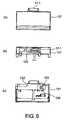
- Figs. 5 are explanatory schematic views illustrating an internal configuration of the terminal cover 12.
- Figs. 6 are views illustrating a state in which the battery-charging plug connector 17-1 is fixed to a first fixing position on the terminal cover 12.
- Figs. 7 are views illustrating a state in which the other battery-charging plug connector 17-2 is fixed to a second fixing position on the terminal cover 12.
- Fig. 4 illustrates a configuration in which the terminal cover 12 is removed from the main mounting surface 11 a of the portable information terminal holding base 10 of Fig. 1 .
- grooves and claws for fixing the terminal cover 12 are formed on the main mounting surface 11 a at a position where the terminal cover 12 is to be fixed.
- the terminal cover 12 is latched onto the main mounting surface 11a of the portable information terminal holding base 10 with the claws.
- the terminal cover 12 is pushed in a horizontal direction toward the cushions 15 that are arranged in the X-direction extending parallel to the main mounting surface 11a, the terminal cover 12 can be removed from the main mounting surface 11a.
- the terminal cover 12 can be fixed to the main mounting surface 11 a through a reverse operation.
- the terminal cover 12 to be fixed to the main mounting surface 11 a of the portable information terminal holding base 10 includes a terminal housing section 121 and a terminal pressing plate 122.
- the terminal housing section 121 illustrated in Fig. 5(a) has a space secured to house the battery-charging plug connector 17-1 or 17-2 inside (see Figs. 6 and 7 ). Therefore, the battery-charging plug connector 17-1 or 17-2 can be housed at the first fixing position or the second fixing position in the space formed in the terminal housing section 121 in accordance with the dimensions of the battery-charging plug connector 17-1 or 17-2.
- the battery-charging plug connectors 17-1 and 17-2 are formed compatible with the specifications of the battery-charging slots in the respective portable information terminals.
- the terminal housing section 121 includes a latching claw 123, a fitting groove 126, and a taper 128 for fixing the terminal pressing plate 122.
- the terminal pressing plate 122 illustrated in Fig. 5(b) has a latching hole 124 provided at one end thereof, and an insertion portion 127 formed into a tapered shape at the other end thereof.
- the insertion portion 127 is fitted into the fitting groove 126, and then the latching claw 123 formed on the terminal housing section 121 is engaged with the latching hole 124 of the terminal pressing plate 122.
- An adsorption sheet 125 indicated by the hatched lines may be arranged at an inner wall of each of the first fixing position and the second fixing position on the terminal housing section 121 (see Fig. 5(a) ). Further, an adsorption sheet 125 indicated by the hatched lines is also arranged at an inner wall of the terminal pressing plate 122 that faces the respective fixing positions when the terminal pressing plate 122 is fixed to the terminal housing section 121 (see Fig. 5(b) ).
- the adsorption sheet examples include a special sheet having a thickness of 0.3 mm that is releasable and having micropores formed therein repeatedly, but the adsorption sheet is not limited to this configuration, and any member may be employed as long as the member is capable of more firmly fixing the battery-charging plug connector 17-1 or 17-2.
- the battery-charging plug connector 17-1 is fixed to the first fixing position while being sandwiched between the terminal housing section 121 and the terminal pressing plate 122.
- the battery-charging plug connector 17-1 is provided, as an auxiliary part, to the smartphone having a substantially 3- to 4-inch display installed thereon.
- the battery-charging plug connector 17-1 is fixed while being sandwiched between the terminal housing section 121 and the terminal pressing plate 122.
- the lower end of the battery-charging plug connector 17-1 is supported by the taper 128 formed on the terminal housing section 121, and the battery-charging plug connector 17-1 is further caused to adhere to the adsorption sheets 125. In this manner, the battery-charging plug connector 17-1 can be fixed firmly.
- the battery-charging plug connector 17-2 is fixed to the second fixing position while being sandwiched between the terminal housing section 121 and the terminal pressing plate 122.
- the battery-charging plug connector 17-2 is provided, as an auxiliary part, to the tablet terminal having a substantially 7-inch display installed thereon. Therefore, the battery-charging plug connector 17-2 has larger dimensions than the battery-charging plug connector 17-1 in accordance with the length and width size of the tablet terminal and the position of the battery-charging slot provided at the lower end of the tablet terminal.
- the battery-charging plug connector 17-2 is fixed while being sandwiched between the terminal housing section 121 and the terminal pressing plate 122.
- the lower end of the battery-charging plug connector 17-2 is supported by the taper 128 formed on the terminal housing section 121, and the battery-charging plug connector 17-2 is further caused to adhere to the adsorption sheets 125. In this manner, the battery-charging plug connector 17-2 can be fixed firmly.
- each of the battery-charging plug connectors 17-1 and 17-2 that are formed compatible with the specifications of the battery-charging slots in the first portable information terminal (smartphone) 30 and the second portable information terminal (tablet terminal) 31 can be fixed to the predetermined position on the terminal cover 12 that is fixed to the portable information terminal holding base 10.
- the battery-charging plug connector 17-1 or 17-2 is connected to a power outlet socket through an adapter (not shown) and a power supply cable (not shown) provided inside the portable information terminal holding base 10.
- a charging battery (not shown) may be provided on the back surface of the holding base main body 11.
- the battery-charging plug connector 17-1 or 17-2 can be connected to the above-mentioned charging battery through the adapter and the power supply cable provided inside the portable information terminal holding base 10. Therefore, the secondary battery (lithium ion battery) built into the first or second portable information terminal 30 or 31 can easily be charged even in an environment without the power outlet socket, and in an event of power outage.
- the call receiver section 60 that may be added to the portable information terminal holding base 10 illustrated in the respective figures is mounted to the portable information terminal holding base 10.
- the call receiver section 60 may be removed so that the portable information terminal holding base 10 is used alone.
- the first effect is that the single portable information terminal holding base 10 can hold and charge the variety of portable information terminals 30 and 31.
- the reason is because the plurality of fixing positions compatible with the battery-charging plug connectors 17-1 and 17-2 of the respective portable information terminals 30 and 31 are provided in the terminal cover 12.
- the second effect is that the battery-charging plug connectors 17-1 and 17-2 can be fixed and removed easily.
- the reason is because the adsorption sheets 125 that are releasable repeatedly are arranged in the terminal cover 12 including the terminal housing section 121 and the terminal pressing plate 122.
- the third effect is that the various portable information terminals 30 and 31 can be charged easily.
- the reason is because the charging battery is arranged on the back surface of the holding base main body 11.
- the second embodiment of this invention is a modification example of the above-mentioned first embodiment.
- the parts having similar functions to those of the parts described in the first embodiment are hereinafter represented by the same reference symbols, and description thereof is therefore omitted herein.
- the Cartesian coordinate system (X,Y,Z) is used herein.
- the X-axis direction refers to the fore-and-aft direction (depth direction) extending parallel to the main mounting surface 11 a
- the Y-axis direction refers to the right-and-left direction (width direction) extending parallel to the main mounting surface 11a and orthogonal to the X-axis direction
- the Z-axis direction refers to the up-and-down direction (height direction) orthogonal to the main mounting surface 11 a.
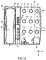
- Figs. 8 to 10 illustrate a portable information terminal holding base 10 according to the second embodiment of this invention.
- Fig. 8 is a perspective view illustrating the portable information terminal holding base 10 according to the second embodiment of this invention.
- Fig. 9 is a perspective view illustrating a state in which a portable information terminal (tablet terminal having a substantially 10-inch display installed thereon) is mounted on the portable information terminal holding base 10 of this embodiment.
- Fig. 10 is a front view illustrating a state in which the terminal cover 12 is removed from the lower end of the main mounting surface 11a of the portable information terminal holding base 10 of this embodiment.
- the portable information terminal holding base 10 illustrated in the figures is a holding base capable of holding one of three types of portable information terminals including the first portable information terminal 30 (see Fig. 2 ) and the second portable information terminal 31 (see Fig. 3 ) described above, and also including a third portable information terminal 40 (see Fig. 9 ) that is different from the portable information terminals 30 and 31 in length and width size and position of a battery-charging slot provided at a lower end thereof.
- the portable information terminal holding base 10 can be used as a battery-charging stand for a portable information terminal under a state in which one of the three types of portable information terminals is held on the portable information terminal holding base 10. Further, instead of using the portable information terminal holding base 10 as a battery-charging stand, the portable information terminal holding base 10 may be used as a holding base for data transfer.
- the third portable information terminal 40 is a tablet terminal (multifunction portable device) such as iPad having a substantially 10-inch display installed thereon. As compared to the first portable information terminal 30 having the minimum length and width size, the third portable information terminal 40 has the maximum length and width size that is twice or more as large as the minimum length and width size of the first portable information terminal 30. Further, the battery-charging slot provided at the lower end of the third portable information terminal 40 is also different from that of the first portable information terminal 30.
- the portable information terminal holding base 10 includes an extensible holding member 13 provided on the first side edge portion side (in the example of the figures, on the right edge portion side) of the holding base main body 11.
- the extensible holding member 13 includes a slide plate 131 that is slidable inside the holding base main body 11 in a direction away from the holding base main body 11 (in the example of the figures, in a rightward direction) (see Fig. 8 ).
- the extensible holding member 13 has an extensible mounting surface 13a that is movable in parallel to the main mounting surface 11a.
- the extensible holding member 13 includes a leg 132 similar to the above-mentioned leg of the holding base main body 11 on a back surface of the extensible holding member 13. Thus, the leg 132 allows the extensible mounting surface 13a to be inclined at a predetermined angle with respect to the horizontal surface.
- the slide plate 131 is formed of a single slide plate alone, but the slide plate 131 is not limited to the single slide plate, and may be formed of a plurality of slide plates. That is, the slide plate may be formed of a plurality of slide plates each extending in the right-and-left direction Y.
- the extensible holding member 13 illustrated in the figures is removable from the holding base main body 11. Further, a side plate 14 is removably arranged on a side edge portion side (in the example of the figures, on a right edge portion side) of the extensible holding member 13 of the portable information terminal holding base 10. When the extensible holding member 13 is to be removed from the holding base main body 11, the side plate 14 may be removed, and the removed side plate 14 may be fixed to the first side edge portion side (in the example of the figures, to the right edge portion side) of the holding base main body 11. In this manner, the portable information terminal holding base 10 may be used in a compact manner.
- the extensible holding member 13 When the extensible holding member 13 is extended to a predetermined extension position as illustrated in Fig. 9 , the extensible holding member 13 can hold the third portable information terminal (tablet terminal) 40 in cooperation with the above-mentioned holding base main body 11.
- the extensible holding member 13 includes a stopper 133 for supporting the lower end of the third portable information terminal (tablet terminal) 40 when the extensible mounting surface 13a is extended to the predetermined extension position.
- six cushions 15 are formed on the main mounting surface 11a, and three cushions 15 are formed on the extensible mounting surface 13a.
- the portable information terminal holding base 10 further includes an expansion battery-charging cover 16 to be fixed to a lower end of the slide plate 131 at a position between the main mounting surface 11a and the extensible mounting surface 13a when the extensible holding member 13 is extended to the predetermined extension position.
- the terminal cover 12 is fixed to the lower end of the main mounting surface 11a, the extensible holding member 13 is extended to the predetermined extension position, and the expansion battery-charging cover 16 is fixed to the lower end of the slide plate 131.
- the lower end of the third portable information terminal (tablet terminal) 40 is supported by the terminal cover 12, the expansion battery-charging cover 16, and the stopper 133 of the extensible holding member 13, and thus the third portable information terminal (tablet terminal) 40 can be held on the main mounting surface 11a and the extensible mounting surface 13a.
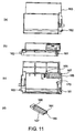
- Fig. 11(a) is a front view illustrating an expansion terminal housing section 163.
- Fig. 11(b) is a top view illustrating the expansion terminal housing section 163.
- Fig. 11(c) is a rear view illustrating the expansion terminal housing section 163.
- Fig. 11(d) is a perspective view illustrating an expansion terminal pressing plate 164.
- the expansion battery-charging cover 16 includes the expansion terminal housing section 163 and the expansion terminal pressing plate 164.
- the expansion terminal housing section 163 illustrated in Fig. 11 (a) has a space secured to house a battery-charging plug connector 17-3 (not shown) inside. Therefore, the battery-charging plug connector 17-3 can be housed at a third fixing position in the space formed in the expansion terminal housing section 163 so as to be compatible with the dimensions of the battery-charging plug connector 17-3 provided to the portable information terminal 40 as an auxiliary part.
- the battery-charging plug connector 17-3 is formed compatible with the specifications of the battery-charging slot in the portable information terminal 40.
- the expansion terminal housing section 163 includes a latching claw 165, a fitting groove 168, and a taper 170 for fixing the expansion terminal pressing plate 164.
- the expansion terminal pressing plate 164 illustrated in Fig. 11 (d) has a latching hole 166 provided at one end thereof, and an insertion portion 169 formed at the other end thereof.
- the expansion terminal pressing plate 164 is to be fixed to the expansion terminal housing section 163, the insertion portion 169 is fitted into the fitting groove 168, and then the latching claw 165 formed on the expansion terminal housing section 163 is engaged with the above-mentioned latching hole 166 of the expansion terminal pressing plate 164.
- An adsorption sheet 167 indicated by the hatched lines is arranged at an inner wall of each of the third fixing position on the expansion terminal housing section 163 that forms the expansion battery-charging cover 16. Further, an adsorption sheet 167 indicated by the hatched lines is also arranged at an inner wall of the expansion terminal pressing plate 164 that faces the third fixing position when the expansion terminal pressing plate 164 is fixed to the expansion terminal housing section 163. Examples of the adsorption sheet 167 include a special sheet having a thickness of 0.3 mm that is releasable and having micropores formed therein repeatedly, but the adsorption sheet is not limited to this configuration, and any member may be employed as long as the member is capable of more firmly fixing the battery-charging plug connector 17-3.
- the battery-charging plug connector 17-3 is fixed to the third fixing position in the expansion battery-charging cover 16 while being sandwiched between the expansion terminal housing section 163 and the expansion terminal pressing plate 164 described above.
- the battery-charging plug connector 17-3 is provided, as an auxiliary part, to the portable information terminal 40 having a substantially 10-inch display installed thereon.
- the battery-charging plug connector 17-3 is fixed while being sandwiched between the expansion terminal housing section 163 and the expansion terminal pressing plate 164.
- the lower end of the battery-charging plug connector 17-3 is supported by the taper 170 formed on the expansion terminal housing section 163, and the battery-charging plug connector 17-3 is further caused to adhere to the adsorption sheet 167. In this manner, the battery-charging plug connector 17-3 can be fixed firmly.
- the battery-charging plug connector 17-3 is connected to the power outlet socket through the adapter (not shown) and the power supply cable (not shown) provided inside the portable information terminal holding base 10.
- a secondary battery (lithium ion battery) built into the above-mentioned portable information terminal 40 can be charged.
- the battery-charging plug connector 17-3 can be connected to the charging battery provided on the back surface of the holding base main body 11 so that the secondary battery (lithium ion battery) built into the above-mentioned portable information terminal 40 is charged.
- the expansion battery-charging cover 16 has a first protrusion 161 at its second side edge portion (left side edge portion), and a second protrusion 162 at its first side edge portion (right side edge portion).
- the holding base main body 11 has a first fitting hole at a lower part of its first side edge portion (right side edge portion), to which the first protrusion 161 is to be fitted.
- the extensible holding member 13 has a second fitting hole at a lower part of its second side edge portion (left side edge portion), to which the second protrusion 162 is to be fitted.
- the extensible holding member 13 is extended to its maximum extension position.
- the first protrusion 161 of the expansion battery-charging cover 16 is fitted to the first fitting hole of the holding base main body 11.
- the second protrusion 162 of the expansion battery-charging cover 16 is fitted to the second fitting hole of the extensible holding member 13.
- the expansion battery-charging cover 16 is fixed to the lower end of the slide plate 131 at the position between the main mounting surface 11a and the extensible mounting surface 13a.
- the first and second protrusions 161 and 162 are provided to the expansion battery-charging cover 16, and the first and second fitting holes are provided to the holding base main body 11 and the extensible holding member 13, respectively, but this invention is not limited to this fitting structure.
- the first protrusion and the second fitting hole may be provided to the expansion battery-charging cover 16, and the first fitting hole and the second protrusion may be provided to the holding base main body 11 and the extensible holding member 13, respectively.
- the first fitting hole and the second protrusion may be provided to the expansion battery-charging cover 16, and the first protrusion and the second fitting hole may be provided to the holding base main body 11 and the extensible holding member 13, respectively.
- the first effect is that the single portable information terminal holding base 10 can hold and charge the variety of portable information terminals 30, 31, and 40.
- the reason is because the plurality of fixing positions compatible with the battery-charging plug connectors 17-1, 17-2, and 17-3 of the respective portable information terminals 30, 31, and 40 are provided.
- the second effect is that the battery-charging plug connectors 17-1, 17-2, and 17-3 can be fixed and removed easily.
- the reason is because the adsorption sheets 125 that are releasable repeatedly are arranged in the terminal cover 12 including the terminal housing section 121 and the terminal pressing plate 122.
- the third effect is that the single portable information terminal holding base 10 can hold and charge the tablet terminal having the maximum length and width size that is twice or more as large as the smartphone having the minimum length and width size.
- the portable information terminal holding base 10 includes the expansion battery-charging cover 16 to be fixed between the main mounting surface 11a and the extensible mounting surface 13a when the extensible holding member 13 provided to the holding base main body 11 is extended.
Landscapes
- Engineering & Computer Science (AREA)
- Signal Processing (AREA)
- Power Engineering (AREA)
- Telephone Set Structure (AREA)
- Telephone Function (AREA)
Claims (7)
- Haltebasis (10) für ein tragbares Informationsendgerät, mit:einem Haltebasishauptkörper (11) mit einer Hauptmontagefläche (11a), die bezüglich einer horizontalen Fläche geneigt ist;wobei der Haltebasishauptkörper dafür konfiguriert ist, auf der Hauptmontagefläche einen von mehreren Typen tragbarer Informationsendgeräte (30, 31, 40) zu halten, die mindestens ein erstes tragbares Informationsendgerät (30) und ein zweites tragbares Informationsendgerät (31) aufweisen, das sich vom ersten tragbaren Informationsendgerät bezüglich der Längen- und der Breitenabmessung und der Position eines an einem unteren Ende davon angeordneten Batterieladeschlitzes unterscheidet; undeiner Batterieladeabdeckung (12), die am Haltebasishauptkörper entfernbar montiert ist und einen Endgerätaufnahmeabschnitt (121) aufweist, der dafür konfiguriert ist, einen von mehreren Typen von Batterieladesteckverbindern (17-1, 17-2) aufzunehmen, die mit den Spezifikationen der Batterieladeschlitze der mehreren Typen tragbarer Informationsendgeräte jeweils kompatibel ausgebildet sind,wobei die Batterieladeabdeckung aufweist:eine Endgerätdrückplatte (122), die dafür vorgesehen ist, am Endgerätaufnahmeabschnitt (121) befestigt zu werden, in dem einer der Batterieladesteckverbinder aufgenommen ist,wobei die Endgerätdrückplatte dafür konfiguriert ist, den einen der Batterieladesteckverbinder an einer ersten Fixierposition oder an einer zweiten Fixierposition zu fixieren,wobei die Batterieladeabdeckung dafür konfiguriert ist:einen Batterieladesteckverbinder (17-1), der mit Spezifikationen eines Batterieladeschlitzes des ersten tragbaren Informationsendgeräts (30) kompatibel ausgebildet ist, an der ersten Fixierposition aufzunehmen; undwenn das zweite tragbare Informationsendgerät (31) auf dem Haltebasishauptkörper gehalten werden soll, einen Batterieladesteckverbinder, der mit Spezifikationen des Batterieladeschlitzes des zweiten tragbaren Informationsendgeräts kompatibel ausgebildet ist, an der zweiten Fixierposition zu fixieren, die gemäß der Längen- und der Breitenabmessung des zweiten tragbaren Informationsendgeräts und der Position des Batterieladeschlitzes des zweiten tragbaren Informationsendgeräts von der ersten Fixierposition verschieden ist,wobei die erste Fixierposition und die zweite Fixierposition Positionen sind, die in einer Vorwärts-Rückwärts-Richtung und in einer Links-Rechts-Richtung verschieden sind, und wobei die erste Fixierposition und die zweite Fixierposition Positionen sind, an denen der eine der Batterieladesteckverbinder, der an der Batterieladeabdeckung fixiert ist, in den einen der Batterieladeschlitze der tragbaren Informationsendgeräte einführbar ist.
- Haltebasis nach Anspruch 1, mit einer Adsorptionsschicht (125) mit darin ausgebildeten Mikroporen,wobei die Adsorptionsschicht auf einer Innenwand des Endgerätaufnahmeabschnitts und auf einer Innenwand der Endgerätdrückplatte an der ersten Fixierposition oder an der zweiten Fixierposition angeordnet ist.
- Haltebasis nach Anspruch 1 oder 2,wobei das erste tragbare Informationsendgerät (30) die kleinste Längen- und Breitenabmessung hat und die mehreren Typen tragbarer Informationsendgeräte mindestens ein drittes tragbares Informationsendgerät (40) mit der größten Längen- und Breitenabmessung aufweisen, die mehr als doppelt so groß sind wie die kleinste Längen- und Breitenabmessung, undwobei die Haltebasis (10) für ein tragbares Informationsendgerät aufweist:ein an einer ersten Seitenrandabschnittseite des Haltebasishauptkörpers angeordnetes ausziehbares Halteelement (13),wobei das ausziehbare Halteelement eine im Inneren des Haltebasishauptkörpers gleitend angeordnete Gleitplatte aufweist,wobei das ausziehbare Halteelement eine parallel zur Hauptmontagefläche bewegliche ausziehbare Montagefläche (13a) aufweist,wobei das ausziehbare Halteelement einen Anschlag (133) zum Stützen eines unteren Endes des zweiten tragbaren Informationsendgeräts aufweist, wenn das ausziehbare Halteelement auf eine vorgegebene Ausziehposition ausgezogen ist, undeine Erweiterungsbatterieladeabdeckung (16), die an einem unteren Ende der Gleitplatte an einer Position zwischen der Hauptmontagefläche und der ausziehbaren Montagefläche entfernbar montiert ist,wobei die Erweiterungsbatterieladeabdeckung (16) dafür konfiguriert ist, einen Batterieladesteckverbinder, der mit Spezifikationen des Batterieladeschlitzes des dritten tragbaren Informationsendgeräts kompatibel ausgebildet ist, an der dritten Fixierposition, die gemäß der Längen- und der Breitenabmessung des dritten tragbaren Informationsendgeräts und einer Position eines Batterieladeschlitzes des dritten tragbaren Informationsendgeräts von der ersten Fixierposition verschieden ist, zu fixieren, wenn das dritte tragbare Informationsendgerät auf dem Haltebasishauptkörper in einem Zustand gehalten werden soll, in dem das ausziehbare Halteelement auf die vorgegebene Ausziehposition ausgezogen ist,
- Haltebasis nach Anspruch 3, wobei die Erweiterungsbatterieabdeckung aufweist:einen Erweiterungsendgerätaufnahmeabschnitt (163), der dafür konfiguriert ist, den einen der mehreren Typen von Batterieladesteckverbindern aufzunehmen, die jeweils mit den Spezifikationen der Batterieladeschlitze der mehreren Typen tragbarer Informationsendgeräte kompatibel ausgebildet sind; undeine Erweiterungsendgerätdrückplatte (164), die dafür vorgesehen ist, am Erweiterungsendgerätaufnahmeabschnitt mit dem darin aufgenommenen einen der Batterieladesteckverbinder fixiert zu werden,wobei die Erweiterungsendgerätdrückplatte dafür konfiguriert ist, den einen der Batterieladesteckverbinder an der dritten Fixierposition zu fixieren.
- Haltebasis nach Anspruch 4, mit einer Adsorptionsschicht mit darin ausgebildeten Mikroporen,wobei die Adsorptionsschicht auf einer Innenwand des Erweiterungsendgerätaufnahmeabschnitts und auf einer Innenwand der Erweiterungsendgerätdrückplatte an der dritten Fixierposition angeordnet ist.
- Haltebasis nach einem der Ansprüche 3 bis 5,wobei die erste Fixierposition, die zweite Fixierposition und die dritte Fixierposition Positionen sind, die in der Vorwärts-Rückwärts-Richtung und in der Rechts-Links-Richtung voneinander verschieden sind, undwobei die erste Fixierposition, die zweite Fixierposition und die dritte Fixierposition Positionen sind, an denen der eine der Batterieladesteckverbinder, der an der Batterieladeabdeckung oder der Erweiterungsbatterieladeabdeckung fixiert ist, in den einen der Batterieladeschlitze der tragbaren Informationsendgeräte einführbar ist.
- Tischtelefon (50) mit:einer Haltebasis (10) für ein tragbares Informationsendgerät nach einem der Ansprüche 1 bis 6; undeinem auf einer zweiten Seitenrandabschnittseite des Haltebasishauptkörpers angeordneten Anrufempfangsabschnitt (60).
Applications Claiming Priority (2)
| Application Number | Priority Date | Filing Date | Title |
|---|---|---|---|
| JP2011232523A JP5413994B2 (ja) | 2011-10-24 | 2011-10-24 | 携帯型情報端末用保持台、及び卓上電話機 |
| PCT/JP2012/076374 WO2013061797A1 (ja) | 2011-10-24 | 2012-10-04 | 携帯型情報端末用保持台、卓上電話機、及び携帯型情報端末用コネクタの固定方法 |
Publications (3)
| Publication Number | Publication Date |
|---|---|
| EP2773085A1 EP2773085A1 (de) | 2014-09-03 |
| EP2773085A4 EP2773085A4 (de) | 2015-07-29 |
| EP2773085B1 true EP2773085B1 (de) | 2016-09-14 |
Family
ID=48167630
Family Applications (1)
| Application Number | Title | Priority Date | Filing Date |
|---|---|---|---|
| EP12844638.2A Active EP2773085B1 (de) | 2011-10-24 | 2012-10-04 | Halteplattform für mobile informationsendgeräte, desktoptelefon und verfahren zur fixierung eines steckers für mobile informationsendgeräte |
Country Status (7)
| Country | Link |
|---|---|
| US (1) | US8890479B2 (de) |
| EP (1) | EP2773085B1 (de) |
| JP (1) | JP5413994B2 (de) |
| CN (1) | CN103858412B (de) |
| AU (1) | AU2012330183B2 (de) |
| BR (1) | BR112014008740B1 (de) |
| WO (1) | WO2013061797A1 (de) |
Families Citing this family (4)
| Publication number | Priority date | Publication date | Assignee | Title |
|---|---|---|---|---|
| JP5637567B2 (ja) | 2012-09-26 | 2014-12-10 | Necプラットフォームズ株式会社 | クレードル装置 |
| AU354408S (en) * | 2013-12-20 | 2014-03-18 | Nec Platforms | Telephone |
| AU354342S (en) * | 2013-12-20 | 2014-03-17 | Nec Platforms | Telephone |
| JP7699371B2 (ja) * | 2021-07-19 | 2025-06-27 | クツワ株式会社 | スタンド |
Family Cites Families (19)
| Publication number | Priority date | Publication date | Assignee | Title |
|---|---|---|---|---|
| JPH03165298A (ja) * | 1989-11-24 | 1991-07-17 | Toshiba Corp | 原子炉停止装置 |
| US6084963A (en) | 1996-11-01 | 2000-07-04 | Harness System Technologies Research, Ltd. | Phone holder for selectively holding a mobile phone |
| JPH10200611A (ja) * | 1997-01-14 | 1998-07-31 | Harness Sogo Gijutsu Kenkyusho:Kk | 電話機保持装置 |
| JPH11354207A (ja) | 1998-06-10 | 1999-12-24 | Kojima Press Co Ltd | コネクタ装置 |
| JP2000174872A (ja) * | 1998-12-10 | 2000-06-23 | Harness Syst Tech Res Ltd | コネクタモジュール及びコネクタモジュールを備えた電話機ホルダー |
| JP4119626B2 (ja) * | 2001-08-07 | 2008-07-16 | 京セラ株式会社 | 無線電話機用充電装置 |
| JP2004023386A (ja) * | 2002-06-14 | 2004-01-22 | Matsushita Electric Ind Co Ltd | 充電装置および通信端末 |
| CN1700506A (zh) * | 2004-05-18 | 2005-11-23 | 长沼武夫 | 手机充电器 |
| US6994575B1 (en) * | 2004-12-22 | 2006-02-07 | Motorola, Inc. | Desktop charger with adjustable connector module |
| CN101356867B (zh) * | 2006-01-04 | 2012-01-11 | 罗技欧洲公司 | 用于个人音频装置的通用辅助组件连接系统 |
| JP4858056B2 (ja) * | 2006-09-29 | 2012-01-18 | ソニー株式会社 | 音楽機能付きクレードル装置 |
| CN200965900Y (zh) * | 2006-10-30 | 2007-10-24 | 许涛 | 手机接转充电器 |
| JP2008206242A (ja) * | 2007-02-19 | 2008-09-04 | Topland:Kk | 携帯電話機用充電器 |
| WO2009151577A1 (en) * | 2008-06-09 | 2009-12-17 | Byrne Norman R | Docking station for use with power and data center |
| JP5512230B2 (ja) * | 2009-11-02 | 2014-06-04 | 株式会社マキタ | 充電装置 |
| CN201733342U (zh) * | 2010-06-25 | 2011-02-02 | 梁开方 | 插拔式手持终端电话一体机及插拔式充电电话机 |
| TWM399483U (en) * | 2010-09-13 | 2011-03-01 | Powertech Ind Ltd | Electric receptacle with electric charging interface |
| TWM416305U (en) | 2011-03-17 | 2011-11-11 | cheng-jun Zhang | Connection base |
| US9093849B2 (en) * | 2013-01-07 | 2015-07-28 | Superior Communications, Inc. | Universal charging dock with a wall mount |
-
2011
- 2011-10-24 JP JP2011232523A patent/JP5413994B2/ja active Active
-
2012
- 2012-10-04 EP EP12844638.2A patent/EP2773085B1/de active Active
- 2012-10-04 BR BR112014008740-7A patent/BR112014008740B1/pt not_active IP Right Cessation
- 2012-10-04 US US14/350,752 patent/US8890479B2/en active Active
- 2012-10-04 AU AU2012330183A patent/AU2012330183B2/en active Active
- 2012-10-04 CN CN201280049771.9A patent/CN103858412B/zh active Active
- 2012-10-04 WO PCT/JP2012/076374 patent/WO2013061797A1/ja not_active Ceased
Also Published As
| Publication number | Publication date |
|---|---|
| CN103858412A (zh) | 2014-06-11 |
| AU2012330183A1 (en) | 2014-04-17 |
| EP2773085A4 (de) | 2015-07-29 |
| WO2013061797A1 (ja) | 2013-05-02 |
| BR112014008740A2 (pt) | 2017-04-25 |
| AU2012330183B2 (en) | 2014-05-15 |
| JP5413994B2 (ja) | 2014-02-12 |
| CN103858412B (zh) | 2015-11-25 |
| BR112014008740B1 (pt) | 2022-08-09 |
| EP2773085A1 (de) | 2014-09-03 |
| US8890479B2 (en) | 2014-11-18 |
| JP2013090315A (ja) | 2013-05-13 |
| US20140247012A1 (en) | 2014-09-04 |
Similar Documents
| Publication | Publication Date | Title |
|---|---|---|
| AU2012330182B2 (en) | Battery-charging base for mobile information terminals | |
| EP2903244B1 (de) | Halterungsständer für ein tragbares informationsendgerät und schreibtischtelefon | |
| KR101398763B1 (ko) | 휴대용 전자 디바이스용 거치대 | |
| US8335545B2 (en) | Modular charging dock | |
| US20160072327A1 (en) | Dock for Portable Electronic Devices | |
| US20100137038A1 (en) | Interchangeable Docking Cradle | |
| US8890479B2 (en) | Holding platform for mobile information terminals, desktop telephone, and fixing method connector for mobile information terminals | |
| EP2744180B1 (de) | Tragbares informationsendgerät und desktop-telefon | |
| US20150189054A1 (en) | Terminal holding stand including speech function | |
| CN204103200U (zh) | 设备支架和对接站 | |
| EP2903098B1 (de) | Basisstation mit ausgezeichneter verwendbarkeit sowie zuverlässigkeit und einfacher struktur |
Legal Events
| Date | Code | Title | Description |
|---|---|---|---|
| PUAI | Public reference made under article 153(3) epc to a published international application that has entered the european phase |
Free format text: ORIGINAL CODE: 0009012 |
|
| 17P | Request for examination filed |
Effective date: 20140508 |
|
| AK | Designated contracting states |
Kind code of ref document: A1 Designated state(s): AL AT BE BG CH CY CZ DE DK EE ES FI FR GB GR HR HU IE IS IT LI LT LU LV MC MK MT NL NO PL PT RO RS SE SI SK SM TR |
|
| DAX | Request for extension of the european patent (deleted) | ||
| RAP1 | Party data changed (applicant data changed or rights of an application transferred) |
Owner name: NEC PLATFORMS, LTD. |
|
| REG | Reference to a national code |
Ref country code: DE Ref legal event code: R079 Ref document number: 602012023130 Country of ref document: DE Free format text: PREVIOUS MAIN CLASS: H04M0001110000 Ipc: H04M0001020000 |
|
| RA4 | Supplementary search report drawn up and despatched (corrected) |
Effective date: 20150625 |
|
| RIC1 | Information provided on ipc code assigned before grant |
Ipc: B60R 11/02 20060101ALI20150619BHEP Ipc: H01R 27/00 20060101ALI20150619BHEP Ipc: H02J 7/00 20060101ALI20150619BHEP Ipc: H04M 1/11 20060101ALI20150619BHEP Ipc: H04M 1/04 20060101ALI20150619BHEP Ipc: H04M 1/02 20060101AFI20150619BHEP |
|
| GRAP | Despatch of communication of intention to grant a patent |
Free format text: ORIGINAL CODE: EPIDOSNIGR1 |
|
| INTG | Intention to grant announced |
Effective date: 20160513 |
|
| GRAS | Grant fee paid |
Free format text: ORIGINAL CODE: EPIDOSNIGR3 |
|
| GRAA | (expected) grant |
Free format text: ORIGINAL CODE: 0009210 |
|
| AK | Designated contracting states |
Kind code of ref document: B1 Designated state(s): AL AT BE BG CH CY CZ DE DK EE ES FI FR GB GR HR HU IE IS IT LI LT LU LV MC MK MT NL NO PL PT RO RS SE SI SK SM TR |
|
| REG | Reference to a national code |
Ref country code: GB Ref legal event code: FG4D |
|
| REG | Reference to a national code |
Ref country code: CH Ref legal event code: EP |
|
| REG | Reference to a national code |
Ref country code: IE Ref legal event code: FG4D |
|
| REG | Reference to a national code |
Ref country code: AT Ref legal event code: REF Ref document number: 830091 Country of ref document: AT Kind code of ref document: T Effective date: 20161015 |
|
| REG | Reference to a national code |
Ref country code: DE Ref legal event code: R096 Ref document number: 602012023130 Country of ref document: DE |
|
| REG | Reference to a national code |
Ref country code: FR Ref legal event code: PLFP Year of fee payment: 5 |
|
| REG | Reference to a national code |
Ref country code: LT Ref legal event code: MG4D |
|
| REG | Reference to a national code |
Ref country code: NL Ref legal event code: MP Effective date: 20160914 |
|
| PG25 | Lapsed in a contracting state [announced via postgrant information from national office to epo] |
Ref country code: HR Free format text: LAPSE BECAUSE OF FAILURE TO SUBMIT A TRANSLATION OF THE DESCRIPTION OR TO PAY THE FEE WITHIN THE PRESCRIBED TIME-LIMIT Effective date: 20160914 Ref country code: FI Free format text: LAPSE BECAUSE OF FAILURE TO SUBMIT A TRANSLATION OF THE DESCRIPTION OR TO PAY THE FEE WITHIN THE PRESCRIBED TIME-LIMIT Effective date: 20160914 Ref country code: LT Free format text: LAPSE BECAUSE OF FAILURE TO SUBMIT A TRANSLATION OF THE DESCRIPTION OR TO PAY THE FEE WITHIN THE PRESCRIBED TIME-LIMIT Effective date: 20160914 Ref country code: RS Free format text: LAPSE BECAUSE OF FAILURE TO SUBMIT A TRANSLATION OF THE DESCRIPTION OR TO PAY THE FEE WITHIN THE PRESCRIBED TIME-LIMIT Effective date: 20160914 Ref country code: NO Free format text: LAPSE BECAUSE OF FAILURE TO SUBMIT A TRANSLATION OF THE DESCRIPTION OR TO PAY THE FEE WITHIN THE PRESCRIBED TIME-LIMIT Effective date: 20161214 |
|
| REG | Reference to a national code |
Ref country code: AT Ref legal event code: MK05 Ref document number: 830091 Country of ref document: AT Kind code of ref document: T Effective date: 20160914 |
|
| PG25 | Lapsed in a contracting state [announced via postgrant information from national office to epo] |
Ref country code: BE Free format text: LAPSE BECAUSE OF NON-PAYMENT OF DUE FEES Effective date: 20161031 Ref country code: LV Free format text: LAPSE BECAUSE OF FAILURE TO SUBMIT A TRANSLATION OF THE DESCRIPTION OR TO PAY THE FEE WITHIN THE PRESCRIBED TIME-LIMIT Effective date: 20160914 Ref country code: GR Free format text: LAPSE BECAUSE OF FAILURE TO SUBMIT A TRANSLATION OF THE DESCRIPTION OR TO PAY THE FEE WITHIN THE PRESCRIBED TIME-LIMIT Effective date: 20161215 Ref country code: NL Free format text: LAPSE BECAUSE OF FAILURE TO SUBMIT A TRANSLATION OF THE DESCRIPTION OR TO PAY THE FEE WITHIN THE PRESCRIBED TIME-LIMIT Effective date: 20160914 Ref country code: SE Free format text: LAPSE BECAUSE OF FAILURE TO SUBMIT A TRANSLATION OF THE DESCRIPTION OR TO PAY THE FEE WITHIN THE PRESCRIBED TIME-LIMIT Effective date: 20160914 |
|
| PG25 | Lapsed in a contracting state [announced via postgrant information from national office to epo] |
Ref country code: EE Free format text: LAPSE BECAUSE OF FAILURE TO SUBMIT A TRANSLATION OF THE DESCRIPTION OR TO PAY THE FEE WITHIN THE PRESCRIBED TIME-LIMIT Effective date: 20160914 Ref country code: RO Free format text: LAPSE BECAUSE OF FAILURE TO SUBMIT A TRANSLATION OF THE DESCRIPTION OR TO PAY THE FEE WITHIN THE PRESCRIBED TIME-LIMIT Effective date: 20160914 |
|
| PG25 | Lapsed in a contracting state [announced via postgrant information from national office to epo] |
Ref country code: BE Free format text: LAPSE BECAUSE OF FAILURE TO SUBMIT A TRANSLATION OF THE DESCRIPTION OR TO PAY THE FEE WITHIN THE PRESCRIBED TIME-LIMIT Effective date: 20160914 Ref country code: SK Free format text: LAPSE BECAUSE OF FAILURE TO SUBMIT A TRANSLATION OF THE DESCRIPTION OR TO PAY THE FEE WITHIN THE PRESCRIBED TIME-LIMIT Effective date: 20160914 Ref country code: SM Free format text: LAPSE BECAUSE OF FAILURE TO SUBMIT A TRANSLATION OF THE DESCRIPTION OR TO PAY THE FEE WITHIN THE PRESCRIBED TIME-LIMIT Effective date: 20160914 Ref country code: PT Free format text: LAPSE BECAUSE OF FAILURE TO SUBMIT A TRANSLATION OF THE DESCRIPTION OR TO PAY THE FEE WITHIN THE PRESCRIBED TIME-LIMIT Effective date: 20170116 Ref country code: BG Free format text: LAPSE BECAUSE OF FAILURE TO SUBMIT A TRANSLATION OF THE DESCRIPTION OR TO PAY THE FEE WITHIN THE PRESCRIBED TIME-LIMIT Effective date: 20161214 Ref country code: ES Free format text: LAPSE BECAUSE OF FAILURE TO SUBMIT A TRANSLATION OF THE DESCRIPTION OR TO PAY THE FEE WITHIN THE PRESCRIBED TIME-LIMIT Effective date: 20160914 Ref country code: PL Free format text: LAPSE BECAUSE OF FAILURE TO SUBMIT A TRANSLATION OF THE DESCRIPTION OR TO PAY THE FEE WITHIN THE PRESCRIBED TIME-LIMIT Effective date: 20160914 Ref country code: IS Free format text: LAPSE BECAUSE OF FAILURE TO SUBMIT A TRANSLATION OF THE DESCRIPTION OR TO PAY THE FEE WITHIN THE PRESCRIBED TIME-LIMIT Effective date: 20170114 Ref country code: CZ Free format text: LAPSE BECAUSE OF FAILURE TO SUBMIT A TRANSLATION OF THE DESCRIPTION OR TO PAY THE FEE WITHIN THE PRESCRIBED TIME-LIMIT Effective date: 20160914 Ref country code: AT Free format text: LAPSE BECAUSE OF FAILURE TO SUBMIT A TRANSLATION OF THE DESCRIPTION OR TO PAY THE FEE WITHIN THE PRESCRIBED TIME-LIMIT Effective date: 20160914 |
|
| REG | Reference to a national code |
Ref country code: CH Ref legal event code: PL |
|
| REG | Reference to a national code |
Ref country code: DE Ref legal event code: R097 Ref document number: 602012023130 Country of ref document: DE |
|
| PG25 | Lapsed in a contracting state [announced via postgrant information from national office to epo] |
Ref country code: IT Free format text: LAPSE BECAUSE OF FAILURE TO SUBMIT A TRANSLATION OF THE DESCRIPTION OR TO PAY THE FEE WITHIN THE PRESCRIBED TIME-LIMIT Effective date: 20160914 |
|
| PLBE | No opposition filed within time limit |
Free format text: ORIGINAL CODE: 0009261 |
|
| STAA | Information on the status of an ep patent application or granted ep patent |
Free format text: STATUS: NO OPPOSITION FILED WITHIN TIME LIMIT |
|
| REG | Reference to a national code |
Ref country code: IE Ref legal event code: MM4A |
|
| PG25 | Lapsed in a contracting state [announced via postgrant information from national office to epo] |
Ref country code: LI Free format text: LAPSE BECAUSE OF NON-PAYMENT OF DUE FEES Effective date: 20161031 Ref country code: CH Free format text: LAPSE BECAUSE OF NON-PAYMENT OF DUE FEES Effective date: 20161031 Ref country code: DK Free format text: LAPSE BECAUSE OF FAILURE TO SUBMIT A TRANSLATION OF THE DESCRIPTION OR TO PAY THE FEE WITHIN THE PRESCRIBED TIME-LIMIT Effective date: 20160914 |
|
| 26N | No opposition filed |
Effective date: 20170615 |
|
| PG25 | Lapsed in a contracting state [announced via postgrant information from national office to epo] |
Ref country code: LU Free format text: LAPSE BECAUSE OF NON-PAYMENT OF DUE FEES Effective date: 20161004 |
|
| REG | Reference to a national code |
Ref country code: FR Ref legal event code: PLFP Year of fee payment: 6 |
|
| PG25 | Lapsed in a contracting state [announced via postgrant information from national office to epo] |
Ref country code: SI Free format text: LAPSE BECAUSE OF FAILURE TO SUBMIT A TRANSLATION OF THE DESCRIPTION OR TO PAY THE FEE WITHIN THE PRESCRIBED TIME-LIMIT Effective date: 20160914 Ref country code: IE Free format text: LAPSE BECAUSE OF NON-PAYMENT OF DUE FEES Effective date: 20161004 |
|
| PG25 | Lapsed in a contracting state [announced via postgrant information from national office to epo] |
Ref country code: HU Free format text: LAPSE BECAUSE OF FAILURE TO SUBMIT A TRANSLATION OF THE DESCRIPTION OR TO PAY THE FEE WITHIN THE PRESCRIBED TIME-LIMIT; INVALID AB INITIO Effective date: 20121004 |
|
| PG25 | Lapsed in a contracting state [announced via postgrant information from national office to epo] |
Ref country code: MK Free format text: LAPSE BECAUSE OF FAILURE TO SUBMIT A TRANSLATION OF THE DESCRIPTION OR TO PAY THE FEE WITHIN THE PRESCRIBED TIME-LIMIT Effective date: 20160914 Ref country code: CY Free format text: LAPSE BECAUSE OF FAILURE TO SUBMIT A TRANSLATION OF THE DESCRIPTION OR TO PAY THE FEE WITHIN THE PRESCRIBED TIME-LIMIT Effective date: 20160914 Ref country code: MT Free format text: LAPSE BECAUSE OF NON-PAYMENT OF DUE FEES Effective date: 20161031 Ref country code: MC Free format text: LAPSE BECAUSE OF FAILURE TO SUBMIT A TRANSLATION OF THE DESCRIPTION OR TO PAY THE FEE WITHIN THE PRESCRIBED TIME-LIMIT Effective date: 20160914 |
|
| REG | Reference to a national code |
Ref country code: FR Ref legal event code: PLFP Year of fee payment: 7 |
|
| PG25 | Lapsed in a contracting state [announced via postgrant information from national office to epo] |
Ref country code: TR Free format text: LAPSE BECAUSE OF FAILURE TO SUBMIT A TRANSLATION OF THE DESCRIPTION OR TO PAY THE FEE WITHIN THE PRESCRIBED TIME-LIMIT Effective date: 20160914 Ref country code: AL Free format text: LAPSE BECAUSE OF FAILURE TO SUBMIT A TRANSLATION OF THE DESCRIPTION OR TO PAY THE FEE WITHIN THE PRESCRIBED TIME-LIMIT Effective date: 20160914 |
|
| PGFP | Annual fee paid to national office [announced via postgrant information from national office to epo] |
Ref country code: DE Payment date: 20251021 Year of fee payment: 14 |
|
| PGFP | Annual fee paid to national office [announced via postgrant information from national office to epo] |
Ref country code: GB Payment date: 20251022 Year of fee payment: 14 |
|
| PGFP | Annual fee paid to national office [announced via postgrant information from national office to epo] |
Ref country code: FR Payment date: 20251030 Year of fee payment: 14 |