EP2772716A2 - Heat exchanger assembly - Google Patents
Heat exchanger assembly Download PDFInfo
- Publication number
- EP2772716A2 EP2772716A2 EP14156127.4A EP14156127A EP2772716A2 EP 2772716 A2 EP2772716 A2 EP 2772716A2 EP 14156127 A EP14156127 A EP 14156127A EP 2772716 A2 EP2772716 A2 EP 2772716A2
- Authority
- EP
- European Patent Office
- Prior art keywords
- heat exchanger
- end plate
- exchanger assembly
- folded fin
- fin core
- Prior art date
- Legal status (The legal status is an assumption and is not a legal conclusion. Google has not performed a legal analysis and makes no representation as to the accuracy of the status listed.)
- Granted
Links
Images



Classifications
-
- F—MECHANICAL ENGINEERING; LIGHTING; HEATING; WEAPONS; BLASTING
- F28—HEAT EXCHANGE IN GENERAL
- F28F—DETAILS OF HEAT-EXCHANGE AND HEAT-TRANSFER APPARATUS, OF GENERAL APPLICATION
- F28F3/00—Plate-like or laminated elements; Assemblies of plate-like or laminated elements
- F28F3/02—Elements or assemblies thereof with means for increasing heat-transfer area, e.g. with fins, with recesses, with corrugations
- F28F3/06—Elements or assemblies thereof with means for increasing heat-transfer area, e.g. with fins, with recesses, with corrugations the means being attachable to the element
-
- B—PERFORMING OPERATIONS; TRANSPORTING
- B23—MACHINE TOOLS; METAL-WORKING NOT OTHERWISE PROVIDED FOR
- B23P—METAL-WORKING NOT OTHERWISE PROVIDED FOR; COMBINED OPERATIONS; UNIVERSAL MACHINE TOOLS
- B23P15/00—Making specific metal objects by operations not covered by a single other subclass or a group in this subclass
- B23P15/26—Making specific metal objects by operations not covered by a single other subclass or a group in this subclass heat exchangers or the like
-
- F—MECHANICAL ENGINEERING; LIGHTING; HEATING; WEAPONS; BLASTING
- F28—HEAT EXCHANGE IN GENERAL
- F28D—HEAT-EXCHANGE APPARATUS, NOT PROVIDED FOR IN ANOTHER SUBCLASS, IN WHICH THE HEAT-EXCHANGE MEDIA DO NOT COME INTO DIRECT CONTACT
- F28D9/00—Heat-exchange apparatus having stationary plate-like or laminated conduit assemblies for both heat-exchange media, the media being in contact with different sides of a conduit wall
- F28D9/0025—Heat-exchange apparatus having stationary plate-like or laminated conduit assemblies for both heat-exchange media, the media being in contact with different sides of a conduit wall the conduits being formed by zig-zag bend plates
-
- F—MECHANICAL ENGINEERING; LIGHTING; HEATING; WEAPONS; BLASTING
- F28—HEAT EXCHANGE IN GENERAL
- F28F—DETAILS OF HEAT-EXCHANGE AND HEAT-TRANSFER APPARATUS, OF GENERAL APPLICATION
- F28F9/00—Casings; Header boxes; Auxiliary supports for elements; Auxiliary members within casings
- F28F9/001—Casings in the form of plate-like arrangements; Frames enclosing a heat exchange core
-
- Y—GENERAL TAGGING OF NEW TECHNOLOGICAL DEVELOPMENTS; GENERAL TAGGING OF CROSS-SECTIONAL TECHNOLOGIES SPANNING OVER SEVERAL SECTIONS OF THE IPC; TECHNICAL SUBJECTS COVERED BY FORMER USPC CROSS-REFERENCE ART COLLECTIONS [XRACs] AND DIGESTS
- Y10—TECHNICAL SUBJECTS COVERED BY FORMER USPC
- Y10T—TECHNICAL SUBJECTS COVERED BY FORMER US CLASSIFICATION
- Y10T29/00—Metal working
- Y10T29/49—Method of mechanical manufacture
- Y10T29/4935—Heat exchanger or boiler making
Definitions
- the present application relates generally to a heat exchanger assembly and more particularly relates to a folded fin air to air heat exchanger assembly having end plates with a number of protrusions thereon.
- heat exchanger designs are known for exchanging heat between two or more mediums.
- certain types of heat exchangers are better suited for certain types of applications.
- electronic control systems such as power plant control systems and the like may have relatively high operating temperatures given the use of high density electrical components.
- Air to air heat exchangers have been found to be effective in cooling such controls in an efficient manner.
- the folded fin heat exchanger may be formed by folding a continuous sheet of thermally conductive material so as to create a repeating "U-shaped" profile.
- folded fin heat exchangers may provide efficient heat exchange, there may be issues in the assembly, joining, and handling of the various components within such a heat exchanger.
- an outside fixture may be required for dip brazing or other types of flow based metal joining. The use of such fixtures may add cost and complexity to the manufacturing and assembly processes.
- the present application and the resultant patent thus provide a heat exchanger assembly.
- the heat exchanger assembly may include a folded fin core with a ridge end and a trough end, a first end plate positioned about the ridge end of the folded fin core, a second end plate positioned about the trough end of the folded fin core, and with the first end plate and the second end plate including a number of protrusions thereon.
- the present application and the resultant patent further provide a method of assembling a heat exchanger assembly.
- the method may include the steps of positioning a first end plate with a first number of protrusions about a ridge end of a fold fin core, positioning a first side plate into a first side last protrusion on the first end plate, positioning a second side plate into a second side last protrusion on the first end plate, positioning a second end plate with a second number of protrusions about a trough end of the folded fin core, the first side plate, and the second side plate, and joining the folded fin core, the first end plate, the second end plate, the first side plate, and the second side plate in a flow based metal joining process.
- the present application and the resultant patent further provide an air to air heat exchanger assembly.
- the air to air heat exchanger may include a folded fin core with a number of fin walls with a number of ridges and a number of troughs there between, a ridge end, and a trough end, a first end plate positioned about the ridge end of the folded fin core, and a second end plate positioned about the trough end of the folded fin core.
- the first end plate and the second end plate both include a number of protrusions thereon to accommodate the ridges and the troughs of the folded fin core thereabout.
- Figs. 1 and 2 show a heat exchanger assembly 100 as may be described herein.
- the heat exchanger assembly 100 may be an air-to-air exchanger 110, and more specifically, a folded fin air to air heat exchanger 120.
- Other types of heat exchanger assemblies 100 may be used herein.
- the heat exchanger assembly 100 may have any size, shape, or configuration.
- the heat exchanger assembly 100 may include a folded fin core 130.
- the folded fin core 130 may be enclosed in part by a first end plate 140, a second end plate 150, a first side plate 160, and a second side plate 170.
- the combination of the elements herein may provide a fluid-tight barrier between the opposite sides of the exposed area of the folded fin core 130.
- the individual components of the heat exchanger assembly 100 may have any size, shape, or configuration. Other types of components also may be used herein.
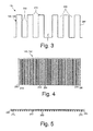
- Fig. 3 shows an exaggerated view of the folded fin core 130.
- the folded fin core 130 may be made from a continuous sheet 180 of a thermally conductive material 190.
- the thermally conductive material 190 may be aluminum, an aluminum based alloy, or other types of materials with good heat transfer and structural characteristics.
- the continuous sheet 180 may be folded so as to form any number of substantially parallel fin walls 200.
- the fin walls 200 may be spaced apart from one another by alternating flat ridges 210 and troughs 220. Each pair of fin walls 200 may be spaced apart by the flat ridges 210 to form each trough 220 for a repeating "U-shape".
- the folded fin core 130 may have any size, shape, or configuration. As will be explained in more detail below, the folded fin core 130 may extend from a first end or a rigid end 230 to a second end or a trough end 240.
- Figs. 4 and 5 show an example of one of the end plates 140, 150.
- the first end plate 140 and the second end plate 150 may be substantially identical and need not be described separately.
- Each end plate 140, 150 may include a flat surface 250 with a number of protrusions 260 extending therefrom.
- the protrusions 260 may conform to the shape and the fin pitch of the fin walls 200 of the folded fin core 130.
- An example of one of the protrusions 260 is shown in Fig. 6 . Any number of the protrusions 260 may be used herein.
- a second to last protrusion 270 on both ends of the end plates 140, 150 may be sized to accommodate an outer one-half folded fin 280 of the folded fin core 130.
- a last protrusion 290 on both sides of the end plate 140, 150 may be sized to accommodate the side plates 160, 170 therein.
- Fig. 7 shows an example of the second to last protrusion 270 and the last protrusion 290.
- Other components and other configurations may be used herein.
- Fig. 8 shows the ridge end 230 of the folded fin core 130 positioned about the first end plate 140.
- Fig. 9 shows the trough end 240 of the folded fin core 130 positioned about the second end plate 150.
- the troughs 220 and the fin walls 200 are sized to envelope the protrusions 260 in the ridge end 230.
- the troughs 220 expose the protrusions 260 in the trough end 240 while the ridges 210 fill the spaces between the protrusions 260.
- Fig. 10 shows the addition of the side plates 160, 170 in the last protrusions 290 of the end plates 140, 150.
- the side plates 160, 170 add further mechanical support to the heat exchanger assembly 100 as a whole.
- Other components and other configurations may be used herein.
- the end plates 140, 150 may be positioned about the folded fin core 130. Specifically, the ridge end 230 and the trough end 240 may be positioned within and adjacent to the protrusions 260 on the end plates 140. Likewise, the side plates 160, 170 may be positioned within the last protrusions 290 of the end plates 140, 150.
- This configuration provides structural rigidity to the heat exchanger assembly 100 for handling before the components are joined. Moreover, a separate fixture or jigging may not be required for the bonding process.
- the fin walls 200 and the protrusions 260 may be spaced with sufficient clearance for adequate metal bonding flux flow and bonding filler material for dip brazing or other types of flow based metal joining while providing physical rigidity before and during the bonding process.
- Other types of metal joining means may be used herein.
- the heat exchanger assembly 100 thus provides self-fixturing or self-jigging prior to the metal joining process and provides structural rigidity after the bonding process.
- the heat exchanger assembly 100 also provides means of sealing the end plates for a physical, airtight barrier for sealed heat exchanger operations. Moreover, the bonding process causes higher yield production quality parts.
- the heat exchanger assembly 100 thus provides efficient heat exchange with an overall simplified manufacturing process.
- the heat exchanger assembly 100 may have many different applications.
- Fig. 11 shows the use of the heat exchanger assembly 100 with a pair of fan plenums 100 to force a flow of air there through.
- the heat exchanger assembly 100 with the fan plenums 300 or other types of devices may be used to cool a component 310, such as an electrical, heat generating component and the like. Many other applications may be used herein.
Landscapes
- Engineering & Computer Science (AREA)
- Mechanical Engineering (AREA)
- Physics & Mathematics (AREA)
- Thermal Sciences (AREA)
- General Engineering & Computer Science (AREA)
- Heat-Exchange Devices With Radiators And Conduit Assemblies (AREA)
Abstract
Description
- The present application relates generally to a heat exchanger assembly and more particularly relates to a folded fin air to air heat exchanger assembly having end plates with a number of protrusions thereon.
- Many different types of heat exchanger designs are known for exchanging heat between two or more mediums. Moreover, certain types of heat exchangers are better suited for certain types of applications. For example, electronic control systems such as power plant control systems and the like may have relatively high operating temperatures given the use of high density electrical components. Air to air heat exchangers have been found to be effective in cooling such controls in an efficient manner.
- One type of air-to-air heat exchanger is a folded fin heat exchanger. The folded fin heat exchanger may be formed by folding a continuous sheet of thermally conductive material so as to create a repeating "U-shaped" profile. Although such folded fin heat exchangers may provide efficient heat exchange, there may be issues in the assembly, joining, and handling of the various components within such a heat exchanger. Specifically, an outside fixture may be required for dip brazing or other types of flow based metal joining. The use of such fixtures may add cost and complexity to the manufacturing and assembly processes.
- There is thus a desire for an improved heat exchanger assembly and a method of constructing the same. Specifically, there is a desire for an improved folded fin air to air heat exchanger with a simplified method of assembly and improved structural rigidity.
- The present application and the resultant patent thus provide a heat exchanger assembly. The heat exchanger assembly may include a folded fin core with a ridge end and a trough end, a first end plate positioned about the ridge end of the folded fin core, a second end plate positioned about the trough end of the folded fin core, and with the first end plate and the second end plate including a number of protrusions thereon.
- The present application and the resultant patent further provide a method of assembling a heat exchanger assembly. The method may include the steps of positioning a first end plate with a first number of protrusions about a ridge end of a fold fin core, positioning a first side plate into a first side last protrusion on the first end plate, positioning a second side plate into a second side last protrusion on the first end plate, positioning a second end plate with a second number of protrusions about a trough end of the folded fin core, the first side plate, and the second side plate, and joining the folded fin core, the first end plate, the second end plate, the first side plate, and the second side plate in a flow based metal joining process.
- The present application and the resultant patent further provide an air to air heat exchanger assembly. The air to air heat exchanger may include a folded fin core with a number of fin walls with a number of ridges and a number of troughs there between, a ridge end, and a trough end, a first end plate positioned about the ridge end of the folded fin core, and a second end plate positioned about the trough end of the folded fin core. The first end plate and the second end plate both include a number of protrusions thereon to accommodate the ridges and the troughs of the folded fin core thereabout.
- These and other features and improvements of the present application and the resultant patent will become apparent to one of ordinary skill in the art upon review of the following detailed description when taken in conjunction with the several drawings and the appended claims.
-
-
Fig. 1 is a perspective view of a heat exchanger assembly as may be described herein. -
Fig. 2 is a further perspective view of the heat exchanger assembly ofFig. 1 . -
Fig. 3 is a side plan view of a folded fin core for use with the heat exchanger assembly ofFig. 1 . -
Fig. 4 is a top plan view of an end plate that may be used with the exchanger assembly ofFig. 1 . -
Fig. 5 is a side plan view of the end plate ofFig. 4 . -
Fig. 6 is a side plan view of a protrusion on the end plate ofFig. 4 -
Fig. 7 is a side view of a second to last protrusion and a last protrusion on the end plate ofFig. 4 . -
Fig. 8 is a perspective view of a ridge end of the heat exchanger assembly ofFig. 1 . -
Fig. 9 is a perspective view of a trough end of the heat exchanger assembly ofFig. 1 . -
Fig. 10 is a perspective view of the ridge end of the heat exchanger assembly ofFig. 1 with a side plate. -
Fig. 11 is an exploded view of the heat exchanger assembly ofFig. 1 with a pair of fan plenums. - Referring now to the drawings, in which like numerals refer to like elements throughout the several views,
Figs. 1 and 2 show aheat exchanger assembly 100 as may be described herein. In this example, theheat exchanger assembly 100 may be an air-to-air exchanger 110, and more specifically, a folded fin air to air heat exchanger 120. Other types ofheat exchanger assemblies 100 may be used herein. Theheat exchanger assembly 100 may have any size, shape, or configuration. - The
heat exchanger assembly 100 may include a foldedfin core 130. The foldedfin core 130 may be enclosed in part by afirst end plate 140, asecond end plate 150, afirst side plate 160, and asecond side plate 170. The combination of the elements herein may provide a fluid-tight barrier between the opposite sides of the exposed area of the foldedfin core 130. The individual components of theheat exchanger assembly 100 may have any size, shape, or configuration. Other types of components also may be used herein. -
Fig. 3 shows an exaggerated view of the foldedfin core 130. The foldedfin core 130 may be made from a continuous sheet 180 of a thermally conductive material 190. The thermally conductive material 190 may be aluminum, an aluminum based alloy, or other types of materials with good heat transfer and structural characteristics. The continuous sheet 180 may be folded so as to form any number of substantiallyparallel fin walls 200. Thefin walls 200 may be spaced apart from one another by alternatingflat ridges 210 andtroughs 220. Each pair offin walls 200 may be spaced apart by theflat ridges 210 to form eachtrough 220 for a repeating "U-shape". The foldedfin core 130 may have any size, shape, or configuration. As will be explained in more detail below, the foldedfin core 130 may extend from a first end or arigid end 230 to a second end or atrough end 240. -
Figs. 4 and 5 show an example of one of theend plates first end plate 140 and thesecond end plate 150 may be substantially identical and need not be described separately. Eachend plate flat surface 250 with a number ofprotrusions 260 extending therefrom. Theprotrusions 260 may conform to the shape and the fin pitch of thefin walls 200 of the foldedfin core 130. An example of one of theprotrusions 260 is shown inFig. 6 . Any number of theprotrusions 260 may be used herein. A second tolast protrusion 270 on both ends of theend plates fin 280 of the foldedfin core 130. Alast protrusion 290 on both sides of theend plate side plates Fig. 7 shows an example of the second tolast protrusion 270 and thelast protrusion 290. Other components and other configurations may be used herein. -
Fig. 8 shows theridge end 230 of the foldedfin core 130 positioned about thefirst end plate 140.Fig. 9 shows thetrough end 240 of the foldedfin core 130 positioned about thesecond end plate 150. As is shown in this example, thetroughs 220 and thefin walls 200 are sized to envelope theprotrusions 260 in theridge end 230. Likewise, thetroughs 220 expose theprotrusions 260 in thetrough end 240 while theridges 210 fill the spaces between theprotrusions 260.Fig. 10 shows the addition of theside plates last protrusions 290 of theend plates side plates heat exchanger assembly 100 as a whole. Other components and other configurations may be used herein. - In use, the
end plates fin core 130. Specifically, theridge end 230 and thetrough end 240 may be positioned within and adjacent to theprotrusions 260 on theend plates 140. Likewise, theside plates last protrusions 290 of theend plates heat exchanger assembly 100 for handling before the components are joined. Moreover, a separate fixture or jigging may not be required for the bonding process. Specifically, thefin walls 200 and theprotrusions 260 may be spaced with sufficient clearance for adequate metal bonding flux flow and bonding filler material for dip brazing or other types of flow based metal joining while providing physical rigidity before and during the bonding process. Other types of metal joining means may be used herein. - Overall structural rigidity during assembly is further improved by the size of the second to
last protrusions 270 for use with the outer one half foldedfins 280. Likewise, thesidewalls fin core 130. Moreover, the bonding process provides a good mechanical seal so as to provide a physical, airtight barrier for efficient overall operation. - The
heat exchanger assembly 100 thus provides self-fixturing or self-jigging prior to the metal joining process and provides structural rigidity after the bonding process. Theheat exchanger assembly 100 also provides means of sealing the end plates for a physical, airtight barrier for sealed heat exchanger operations. Moreover, the bonding process causes higher yield production quality parts. Theheat exchanger assembly 100 thus provides efficient heat exchange with an overall simplified manufacturing process. - The
heat exchanger assembly 100 may have many different applications. For example,Fig. 11 shows the use of theheat exchanger assembly 100 with a pair offan plenums 100 to force a flow of air there through. Theheat exchanger assembly 100 with thefan plenums 300 or other types of devices may be used to cool acomponent 310, such as an electrical, heat generating component and the like. Many other applications may be used herein. - It should be apparent that the foregoing relates only to certain embodiments of the present application and the resultant patent. Numerous changes and modifications may be made herein by one of ordinary skill in the art without departing from the general spirit and scope of the invention as defined by the following claims and the equivalents thereof.
- Various aspects and embodiments of the present invention are defined by the following numbered clauses:
- 1. A heat exchanger assembly, comprising:
- a folded fin core;
- wherein the folded fin core comprises a ridge end and a trough end;
- a first end plate positioned about the ridge end of the folded fin core;
- a second end plate positioned about the trough end of the folded fin core; and
- wherein the first end plate and the second end plate comprise a plurality of protrusions thereon.
- 2. The heat exchanger assembly of clause, wherein the folded fin core comprises a continuous sheet of a thermally conductive material.
- 3. The heat exchanger assembly of clause 1 or clause 2, wherein the folded fin core comprises a plurality of fin walls.
- 4. The heat exchanger assembly of any preceding clause, wherein the plurality of fin walls comprises a plurality of ridges and a plurality of troughs therebetween.
- 5. The heat exchanger assembly of any preceding clause, wherein the first end plate and the second end plate comprise a flat plate with the plurality of protrusions thereon.
- 6. The heat exchanger assembly of any preceding clause, wherein the folded fin core comprises a first one half folded fin at the ridge end and a second one half folded fin at the trough end.
- 7. The heat exchanger assembly of any preceding clause, wherein the first end plate and the second end plate comprise a first side second to last protrusion sized to accommodate the first one half folded fins and a second side second to last protrusion sized to accommodate the second one half folded fins.
- 8. The heat exchanger assembly of any preceding clause, further comprising a first side plate and a second side plate extending from the first end plate to the second end plate.
- 9. The heat exchanger assembly of any preceding clause, wherein the first end plate and the second end plate comprise a first side last protrusion sized to accommodate the first side plate and a second side last protrusion sized to accommodate the second side plate.
- 10. The heat exchanger assembly of any preceding clause, further comprising a fan plenum positioned about the folded fin core.
- 11. The heat exchanger assembly of any preceding clause, wherein the heat exchanger assembly comprises an air to air heat exchanger.
- 12. A method of assembling a heat exchanger assembly, comprising:
- positioning a first end plate with a first plurality of protrusions about a ridge end of a folded fin core;
- positioning a first side plate into a first side last protrusion on the first end plate;
- positioning a second side plate into a second side last protrusion on the first end plate;
- positioning a second end plate with a second plurality of protrusions about a trough end of the folded fin core, the first side plate, and the second side plate; and
- joining the folded fin core, the first end plate, the second end plate, the first side plate, and the second side plate in a flow based metal joining process.
- 13. The method of assembly of any preceding clause, wherein the joining step is performed without a fixturing device.
- 14. The method of assembly of any preceding clause, wherein the joining step comprises flowing an amount of filler material about the first end plate and the second end plate.
- 15. The method of assembly of any preceding clause, wherein the flow based metal joining process comprises a dip brazing process.
- 16. An air to air heat exchanger assembly, comprising:
- a folded fin core;
- the folded fin core comprising a plurality of fin walls with a plurality of ridges and a plurality of troughs therebetween;
- the folded fin core comprising a ridge end and a trough end;
- a first end plate positioned about the ridge end of the folded fin core;
- a second end plate positioned about the trough end of the folded fin core; and
- wherein the first end plate and the second end plate comprise a plurality of protrusions thereon to accommodate the plurality of ridges and the plurality of troughs of the folded fin core.
- 17. The air to air heat exchanger assembly of any preceding clause, wherein the folded fin core comprises a first one half folded fin at the trough end and a second one half folded fin at the ridge end.
- 18. The air to air heat exchanger assembly of any preceding clause, wherein the first end plate and the second end plate comprise a first side second to last protrusion sized to accommodate the first one half folded fins and a second side second to last protrusion sized to accommodate the second one half folded fins.
- 19. The air to air heat exchanger assembly of any preceding clause, further comprising a first side plate and a second side plate extending from the first end plate to the second end plate so as to provide a fluid tight barrier.
- 20. The air to air heat exchanger assembly of any preceding clause, wherein the first end plate and the second end plate comprise a first side last protrusion sized to accommodate the first side plate and a second side last protrusion sized to accommodate the second side plate.
Claims (15)
- A heat exchanger assembly (100), comprising:a folded fin core (130);wherein the folded fin core comprises a ridge end (230) and a trough end (240);a first end plate (140) positioned about the ridge end of the folded fin core;a second end plate (150) positioned about the trough end of the folded fin core; andwherein the first end plate and the second end plate comprise a plurality of protrusions (260) thereon.
- The heat exchanger assembly of claim 1, wherein the folded fin core comprises a continuous sheet of a thermally conductive material.
- The heat exchanger assembly of claim 1 or claim 2, wherein the folded fin core comprises a plurality of fin walls.
- The heat exchanger assembly of any preceding claim, wherein the plurality of fin walls comprises a plurality of ridges and a plurality of troughs therebetween.
- The heat exchanger assembly of any preceding claim, wherein the first end plate and the second end plate comprise a flat plate with the plurality of protrusions thereon.
- The heat exchanger assembly of any preceding claim, wherein the folded fin core comprises a first one half folded fin at the ridge end and a second one half folded fin at the trough end.
- The heat exchanger assembly of any preceding claim, wherein the first end plate and the second end plate comprise a first side second to last protrusion sized to accommodate the first one half folded fins and a second side second to last protrusion sized to accommodate the second one half folded fins.
- The heat exchanger assembly of any preceding claim, further comprising a first side plate and a second side plate extending from the first end plate to the second end plate.
- The heat exchanger assembly of any preceding claim, wherein the first end plate and the second end plate comprise a first side last protrusion sized to accommodate the first side plate and a second side last protrusion sized to accommodate the second side plate.
- The heat exchanger assembly of any preceding claim, further comprising a fan plenum positioned about the folded fin core.
- The heat exchanger assembly of any preceding claim, wherein the heat exchanger assembly comprises an air to air heat exchanger.
- A method of assembling a heat exchanger assembly, comprising:positioning a first end plate with a first plurality of protrusions about a ridge end of a folded fin core;positioning a first side plate into a first side last protrusion on the first end plate;positioning a second side plate into a second side last protrusion on the first end plate;positioning a second end plate with a second plurality of protrusions about a trough end of the folded fin core, the first side plate, and the second side plate; andjoining the folded fin core, the first end plate, the second end plate, the first side plate, and the second side plate in a flow based metal joining process.
- The method of assembly of claim 12, wherein the joining step is performed without a fixturing device.
- The method of assembly of claim 12 or claim 13, wherein the joining step comprises flowing an amount of filler material about the first end plate and the second end plate.
- An air to air heat exchanger assembly, comprising:a folded fin core;the folded fin core comprising a plurality of fin walls with a plurality of ridges and a plurality of troughs there between;the folded fin core comprising a ridge end and a trough end;a first end plate positioned about the ridge end of the folded fin core;a second end plate positioned about the trough end of the folded fin core; andwherein the first end plate and the second end plate comprise a plurality of protrusions thereon to accommodate the plurality of ridges and the plurality of troughs of the folded fin core.
Applications Claiming Priority (1)
| Application Number | Priority Date | Filing Date | Title |
|---|---|---|---|
| US13/779,869 US9151546B2 (en) | 2013-02-28 | 2013-02-28 | Heat exchanger assembly |
Publications (3)
| Publication Number | Publication Date |
|---|---|
| EP2772716A2 true EP2772716A2 (en) | 2014-09-03 |
| EP2772716A3 EP2772716A3 (en) | 2015-08-12 |
| EP2772716B1 EP2772716B1 (en) | 2020-05-06 |
Family
ID=50190186
Family Applications (1)
| Application Number | Title | Priority Date | Filing Date |
|---|---|---|---|
| EP14156127.4A Not-in-force EP2772716B1 (en) | 2013-02-28 | 2014-02-21 | Heat exchanger assembly |
Country Status (4)
| Country | Link |
|---|---|
| US (1) | US9151546B2 (en) |
| EP (1) | EP2772716B1 (en) |
| JP (1) | JP6420552B2 (en) |
| CN (1) | CN104019677B (en) |
Families Citing this family (1)
| Publication number | Priority date | Publication date | Assignee | Title |
|---|---|---|---|---|
| US20160265854A1 (en) * | 2015-03-09 | 2016-09-15 | J R Thermal LLC | Compact stacked fin heat exchanger |
Family Cites Families (32)
| Publication number | Priority date | Publication date | Assignee | Title |
|---|---|---|---|---|
| GB1183220A (en) | 1967-10-05 | 1970-03-04 | Lummus Co | Improvements in Heat Exchange Apparatus |
| US3640340A (en) * | 1970-11-20 | 1972-02-08 | Baxter Laboratories Inc | Heat exchange device with convoluted heat transfer wall |
| US3907050A (en) | 1974-02-19 | 1975-09-23 | Gen Electric | Heat exchanger housing |
| JPS56163023A (en) | 1980-05-20 | 1981-12-15 | Nishiyodo Kuuchiyouki Kk | Manufacture apparatus for finned heating tube |
| US4541480A (en) | 1982-12-22 | 1985-09-17 | Beckmann Kenneth B | Heat exchanger and method for joining plates thereof |
| FR2608745B1 (en) | 1986-12-17 | 1989-04-28 | Rylewski Eugeniusz | INDEPENDENT HEAT EXCHANGE UNIT BETWEEN A PRIMARY FLUID AND A SECONDARY FLUID, PARTICULARLY AIR FOR VENTILATION AND AIR CONDITIONING OF A PREMISES |
| JPH027706U (en) * | 1988-06-22 | 1990-01-18 | ||
| US5282507A (en) * | 1991-07-08 | 1994-02-01 | Yazaki Corporation | Heat exchange system |
| KR950704665A (en) * | 1993-09-16 | 1995-11-20 | 이시마루 쓰네오 | ALUMINUM HEAT EXCHANGER |
| JP3316783B2 (en) | 1995-09-27 | 2002-08-19 | カルソニックカンセイ株式会社 | Temporary assembly device for heat exchanger core |
| CN2310973Y (en) * | 1997-01-15 | 1999-03-17 | 欧可辉 | Inserter type radiator |
| JPH1194476A (en) | 1997-09-25 | 1999-04-09 | Konica Corp | Heat exchanger |
| TW376171U (en) * | 1998-11-24 | 1999-12-01 | Foxconn Prec Components Co Ltd | Radiating device |
| US6279860B1 (en) | 1999-09-07 | 2001-08-28 | Brett A. Swanger | Heat exchanger housing support |
| US6237354B1 (en) | 1999-10-27 | 2001-05-29 | Charles J. Cromer | Cooling system |
| DE10108185A1 (en) | 2001-02-21 | 2002-08-29 | Xcellsis Gmbh | Multiple plate radiator has plates pressed between at least two closing element so that sufficient seal is provided between media cavities |
| JP2002333295A (en) | 2001-05-09 | 2002-11-22 | Furukawa Electric Co Ltd:The | Heat exchanger |
| DE10302948A1 (en) * | 2003-01-24 | 2004-08-05 | Behr Gmbh & Co. Kg | Heat exchanger, in particular exhaust gas cooler for motor vehicles |
| SG116533A1 (en) * | 2003-03-26 | 2005-11-28 | Toshiba Kk | Semiconductor manufacturing apparatus and method of manufacturing semiconductor device. |
| US6957695B2 (en) | 2003-05-13 | 2005-10-25 | H2Gen Innovations, Inc. | Heat exchanger housing and seals |
| US7108052B2 (en) * | 2003-06-26 | 2006-09-19 | Tellabs Petaluma, Inc. | Low-cost method of forming a heat exchanger with an increased heat transfer efficiency |
| US7018169B2 (en) | 2004-02-23 | 2006-03-28 | General Electric Company | Fluid flow control apparatus |
| US7159649B2 (en) | 2004-03-11 | 2007-01-09 | Thermal Corp. | Air-to-air heat exchanger |
| US7064647B2 (en) | 2004-06-22 | 2006-06-20 | General Electric Company | Fabricated air core reactor |
| JP4527557B2 (en) * | 2005-01-26 | 2010-08-18 | 株式会社ティラド | Heat exchanger |
| JP4293252B2 (en) | 2007-03-19 | 2009-07-08 | ダイキン工業株式会社 | Fin for heat exchanger, guide and method of using the same |
| ES2344768T3 (en) | 2007-04-02 | 2010-09-06 | Arcelik Anonim Sirketi | CONDENSER. |
| DE102009020306A1 (en) | 2008-05-12 | 2010-02-11 | Modine Manufacturing Co., Racine | Heat exchanger and method of assembly |
| TWM355492U (en) * | 2008-09-19 | 2009-04-21 | Asia Vital Components Co Ltd | Sealing cap structure of machine core in heat-exchange machine |
| US7796389B2 (en) | 2008-11-26 | 2010-09-14 | General Electric Company | Method and apparatus for cooling electronics |
| US8157266B2 (en) | 2009-08-17 | 2012-04-17 | Paragon Airheater Technologies, Inc. | Full contact flexible seal assembly for heat exchanger |
| KR101014241B1 (en) | 2010-07-20 | 2011-02-16 | 강창희 | Heat exchanger |
-
2013
- 2013-02-28 US US13/779,869 patent/US9151546B2/en not_active Expired - Fee Related
-
2014
- 2014-02-21 EP EP14156127.4A patent/EP2772716B1/en not_active Not-in-force
- 2014-02-26 JP JP2014034777A patent/JP6420552B2/en not_active Expired - Fee Related
- 2014-02-28 CN CN201410070287.5A patent/CN104019677B/en not_active Expired - Fee Related
Non-Patent Citations (1)
| Title |
|---|
| None |
Also Published As
| Publication number | Publication date |
|---|---|
| US20140238651A1 (en) | 2014-08-28 |
| CN104019677B (en) | 2019-03-01 |
| CN104019677A (en) | 2014-09-03 |
| JP6420552B2 (en) | 2018-11-07 |
| EP2772716B1 (en) | 2020-05-06 |
| US9151546B2 (en) | 2015-10-06 |
| EP2772716A3 (en) | 2015-08-12 |
| JP2014169855A (en) | 2014-09-18 |
Similar Documents
| Publication | Publication Date | Title |
|---|---|---|
| US8944147B2 (en) | Heat exchanger and method for manufacturing same | |
| US8621875B2 (en) | Method of removing heat utilizing geometrically reoriented low-profile phase plane heat pipes | |
| JP5157681B2 (en) | Stacked cooler | |
| CN108139183B (en) | heat exchanger | |
| KR100677719B1 (en) | Soldering method and soldering structure | |
| WO2013032664A2 (en) | Laminated heat sinks | |
| EP2843344A1 (en) | Heat exchanger and heat exchanger manufacturing method | |
| US20120199328A1 (en) | Heat Exchanger Comprising a Tubular Element and a Heat Transfer Element | |
| CN104215101B (en) | Plate-fin heat exchanger | |
| US9151546B2 (en) | Heat exchanger assembly | |
| CN206832096U (en) | A heat exchange component and a plate-fin heat exchanger having the same | |
| CN111306970A (en) | heat exchanger | |
| US12463112B2 (en) | Cooling device | |
| CN101832726B (en) | Heat radiating pipe for heat exchanger and manufacturing method thereof | |
| JP2008078587A (en) | Heat exchange fins | |
| CN103346001B (en) | A kind of plate fin type radiator | |
| JP5382185B2 (en) | Stacked cooler | |
| JP6106546B2 (en) | Heat exchanger | |
| RU139843U1 (en) | RECUPERATOR | |
| WO2015035998A1 (en) | Heat exchanger and methode and use | |
| CN105051480A (en) | Heat exchanger | |
| JP2011185497A (en) | Heat exchanger | |
| JP2011185499A (en) | Heat exchanger | |
| JP2005069585A (en) | COOLING UNIT, COOLER HAVING THE COOLING UNIT, AND COOLING METHOD USING THE COOLER | |
| JP2011185498A (en) | Heat exchanger |
Legal Events
| Date | Code | Title | Description |
|---|---|---|---|
| PUAI | Public reference made under article 153(3) epc to a published international application that has entered the european phase |
Free format text: ORIGINAL CODE: 0009012 |
|
| 17P | Request for examination filed |
Effective date: 20140221 |
|
| AK | Designated contracting states |
Kind code of ref document: A2 Designated state(s): AL AT BE BG CH CY CZ DE DK EE ES FI FR GB GR HR HU IE IS IT LI LT LU LV MC MK MT NL NO PL PT RO RS SE SI SK SM TR |
|
| AX | Request for extension of the european patent |
Extension state: BA ME |
|
| PUAL | Search report despatched |
Free format text: ORIGINAL CODE: 0009013 |
|
| AK | Designated contracting states |
Kind code of ref document: A3 Designated state(s): AL AT BE BG CH CY CZ DE DK EE ES FI FR GB GR HR HU IE IS IT LI LT LU LV MC MK MT NL NO PL PT RO RS SE SI SK SM TR |
|
| AX | Request for extension of the european patent |
Extension state: BA ME |
|
| RIC1 | Information provided on ipc code assigned before grant |
Ipc: F28F 9/00 20060101ALI20150707BHEP Ipc: F28D 9/00 20060101AFI20150707BHEP Ipc: F28F 3/06 20060101ALI20150707BHEP |
|
| R17P | Request for examination filed (corrected) |
Effective date: 20160212 |
|
| RBV | Designated contracting states (corrected) |
Designated state(s): AL AT BE BG CH CY CZ DE DK EE ES FI FR GB GR HR HU IE IS IT LI LT LU LV MC MK MT NL NO PL PT RO RS SE SI SK SM TR |
|
| STAA | Information on the status of an ep patent application or granted ep patent |
Free format text: STATUS: EXAMINATION IS IN PROGRESS |
|
| 17Q | First examination report despatched |
Effective date: 20170309 |
|
| RIC1 | Information provided on ipc code assigned before grant |
Ipc: F28F 3/06 20060101ALI20190813BHEP Ipc: B23P 15/26 20060101ALN20190813BHEP Ipc: F28F 9/00 20060101ALI20190813BHEP Ipc: F28D 9/00 20060101AFI20190813BHEP |
|
| GRAP | Despatch of communication of intention to grant a patent |
Free format text: ORIGINAL CODE: EPIDOSNIGR1 |
|
| STAA | Information on the status of an ep patent application or granted ep patent |
Free format text: STATUS: GRANT OF PATENT IS INTENDED |
|
| RIC1 | Information provided on ipc code assigned before grant |
Ipc: F28F 9/00 20060101ALI20191015BHEP Ipc: F28D 9/00 20060101AFI20191015BHEP Ipc: F28F 3/06 20060101ALI20191015BHEP Ipc: B23P 15/26 20060101ALN20191015BHEP |
|
| INTG | Intention to grant announced |
Effective date: 20191031 |
|
| RIC1 | Information provided on ipc code assigned before grant |
Ipc: F28D 9/00 20060101AFI20191021BHEP Ipc: F28F 3/06 20060101ALI20191021BHEP Ipc: B23P 15/26 20060101ALN20191021BHEP Ipc: F28F 9/00 20060101ALI20191021BHEP |
|
| GRAS | Grant fee paid |
Free format text: ORIGINAL CODE: EPIDOSNIGR3 |
|
| GRAJ | Information related to disapproval of communication of intention to grant by the applicant or resumption of examination proceedings by the epo deleted |
Free format text: ORIGINAL CODE: EPIDOSDIGR1 |
|
| GRAL | Information related to payment of fee for publishing/printing deleted |
Free format text: ORIGINAL CODE: EPIDOSDIGR3 |
|
| STAA | Information on the status of an ep patent application or granted ep patent |
Free format text: STATUS: EXAMINATION IS IN PROGRESS |
|
| GRAP | Despatch of communication of intention to grant a patent |
Free format text: ORIGINAL CODE: EPIDOSNIGR1 |
|
| STAA | Information on the status of an ep patent application or granted ep patent |
Free format text: STATUS: GRANT OF PATENT IS INTENDED |
|
| INTC | Intention to grant announced (deleted) | ||
| RIC1 | Information provided on ipc code assigned before grant |
Ipc: F28F 3/06 20060101ALI20200220BHEP Ipc: F28F 9/00 20060101ALI20200220BHEP Ipc: B23P 15/26 20060101ALN20200220BHEP Ipc: F28D 9/00 20060101AFI20200220BHEP |
|
| GRAA | (expected) grant |
Free format text: ORIGINAL CODE: 0009210 |
|
| STAA | Information on the status of an ep patent application or granted ep patent |
Free format text: STATUS: THE PATENT HAS BEEN GRANTED |
|
| INTG | Intention to grant announced |
Effective date: 20200319 |
|
| RIC1 | Information provided on ipc code assigned before grant |
Ipc: F28F 9/00 20060101ALI20200311BHEP Ipc: F28D 9/00 20060101AFI20200311BHEP Ipc: F28F 3/06 20060101ALI20200311BHEP Ipc: B23P 15/26 20060101ALN20200311BHEP |
|
| AK | Designated contracting states |
Kind code of ref document: B1 Designated state(s): AL AT BE BG CH CY CZ DE DK EE ES FI FR GB GR HR HU IE IS IT LI LT LU LV MC MK MT NL NO PL PT RO RS SE SI SK SM TR |
|
| REG | Reference to a national code |
Ref country code: GB Ref legal event code: FG4D |
|
| REG | Reference to a national code |
Ref country code: AT Ref legal event code: REF Ref document number: 1267439 Country of ref document: AT Kind code of ref document: T Effective date: 20200515 Ref country code: CH Ref legal event code: EP |
|
| REG | Reference to a national code |
Ref country code: IE Ref legal event code: FG4D |
|
| REG | Reference to a national code |
Ref country code: DE Ref legal event code: R096 Ref document number: 602014064811 Country of ref document: DE |
|
| REG | Reference to a national code |
Ref country code: LT Ref legal event code: MG4D |
|
| REG | Reference to a national code |
Ref country code: NL Ref legal event code: MP Effective date: 20200506 |
|
| PG25 | Lapsed in a contracting state [announced via postgrant information from national office to epo] |
Ref country code: GR Free format text: LAPSE BECAUSE OF FAILURE TO SUBMIT A TRANSLATION OF THE DESCRIPTION OR TO PAY THE FEE WITHIN THE PRESCRIBED TIME-LIMIT Effective date: 20200807 Ref country code: NO Free format text: LAPSE BECAUSE OF FAILURE TO SUBMIT A TRANSLATION OF THE DESCRIPTION OR TO PAY THE FEE WITHIN THE PRESCRIBED TIME-LIMIT Effective date: 20200806 Ref country code: IS Free format text: LAPSE BECAUSE OF FAILURE TO SUBMIT A TRANSLATION OF THE DESCRIPTION OR TO PAY THE FEE WITHIN THE PRESCRIBED TIME-LIMIT Effective date: 20200906 Ref country code: LT Free format text: LAPSE BECAUSE OF FAILURE TO SUBMIT A TRANSLATION OF THE DESCRIPTION OR TO PAY THE FEE WITHIN THE PRESCRIBED TIME-LIMIT Effective date: 20200506 Ref country code: SE Free format text: LAPSE BECAUSE OF FAILURE TO SUBMIT A TRANSLATION OF THE DESCRIPTION OR TO PAY THE FEE WITHIN THE PRESCRIBED TIME-LIMIT Effective date: 20200506 Ref country code: FI Free format text: LAPSE BECAUSE OF FAILURE TO SUBMIT A TRANSLATION OF THE DESCRIPTION OR TO PAY THE FEE WITHIN THE PRESCRIBED TIME-LIMIT Effective date: 20200506 Ref country code: PT Free format text: LAPSE BECAUSE OF FAILURE TO SUBMIT A TRANSLATION OF THE DESCRIPTION OR TO PAY THE FEE WITHIN THE PRESCRIBED TIME-LIMIT Effective date: 20200907 |
|
| PG25 | Lapsed in a contracting state [announced via postgrant information from national office to epo] |
Ref country code: LV Free format text: LAPSE BECAUSE OF FAILURE TO SUBMIT A TRANSLATION OF THE DESCRIPTION OR TO PAY THE FEE WITHIN THE PRESCRIBED TIME-LIMIT Effective date: 20200506 Ref country code: HR Free format text: LAPSE BECAUSE OF FAILURE TO SUBMIT A TRANSLATION OF THE DESCRIPTION OR TO PAY THE FEE WITHIN THE PRESCRIBED TIME-LIMIT Effective date: 20200506 Ref country code: RS Free format text: LAPSE BECAUSE OF FAILURE TO SUBMIT A TRANSLATION OF THE DESCRIPTION OR TO PAY THE FEE WITHIN THE PRESCRIBED TIME-LIMIT Effective date: 20200506 Ref country code: BG Free format text: LAPSE BECAUSE OF FAILURE TO SUBMIT A TRANSLATION OF THE DESCRIPTION OR TO PAY THE FEE WITHIN THE PRESCRIBED TIME-LIMIT Effective date: 20200806 |
|
| REG | Reference to a national code |
Ref country code: AT Ref legal event code: MK05 Ref document number: 1267439 Country of ref document: AT Kind code of ref document: T Effective date: 20200506 |
|
| PG25 | Lapsed in a contracting state [announced via postgrant information from national office to epo] |
Ref country code: NL Free format text: LAPSE BECAUSE OF FAILURE TO SUBMIT A TRANSLATION OF THE DESCRIPTION OR TO PAY THE FEE WITHIN THE PRESCRIBED TIME-LIMIT Effective date: 20200506 Ref country code: AL Free format text: LAPSE BECAUSE OF FAILURE TO SUBMIT A TRANSLATION OF THE DESCRIPTION OR TO PAY THE FEE WITHIN THE PRESCRIBED TIME-LIMIT Effective date: 20200506 |
|
| PG25 | Lapsed in a contracting state [announced via postgrant information from national office to epo] |
Ref country code: IT Free format text: LAPSE BECAUSE OF FAILURE TO SUBMIT A TRANSLATION OF THE DESCRIPTION OR TO PAY THE FEE WITHIN THE PRESCRIBED TIME-LIMIT Effective date: 20200506 Ref country code: RO Free format text: LAPSE BECAUSE OF FAILURE TO SUBMIT A TRANSLATION OF THE DESCRIPTION OR TO PAY THE FEE WITHIN THE PRESCRIBED TIME-LIMIT Effective date: 20200506 Ref country code: EE Free format text: LAPSE BECAUSE OF FAILURE TO SUBMIT A TRANSLATION OF THE DESCRIPTION OR TO PAY THE FEE WITHIN THE PRESCRIBED TIME-LIMIT Effective date: 20200506 Ref country code: CZ Free format text: LAPSE BECAUSE OF FAILURE TO SUBMIT A TRANSLATION OF THE DESCRIPTION OR TO PAY THE FEE WITHIN THE PRESCRIBED TIME-LIMIT Effective date: 20200506 Ref country code: SM Free format text: LAPSE BECAUSE OF FAILURE TO SUBMIT A TRANSLATION OF THE DESCRIPTION OR TO PAY THE FEE WITHIN THE PRESCRIBED TIME-LIMIT Effective date: 20200506 Ref country code: DK Free format text: LAPSE BECAUSE OF FAILURE TO SUBMIT A TRANSLATION OF THE DESCRIPTION OR TO PAY THE FEE WITHIN THE PRESCRIBED TIME-LIMIT Effective date: 20200506 Ref country code: ES Free format text: LAPSE BECAUSE OF FAILURE TO SUBMIT A TRANSLATION OF THE DESCRIPTION OR TO PAY THE FEE WITHIN THE PRESCRIBED TIME-LIMIT Effective date: 20200506 Ref country code: AT Free format text: LAPSE BECAUSE OF FAILURE TO SUBMIT A TRANSLATION OF THE DESCRIPTION OR TO PAY THE FEE WITHIN THE PRESCRIBED TIME-LIMIT Effective date: 20200506 |
|
| REG | Reference to a national code |
Ref country code: DE Ref legal event code: R097 Ref document number: 602014064811 Country of ref document: DE |
|
| PG25 | Lapsed in a contracting state [announced via postgrant information from national office to epo] |
Ref country code: PL Free format text: LAPSE BECAUSE OF FAILURE TO SUBMIT A TRANSLATION OF THE DESCRIPTION OR TO PAY THE FEE WITHIN THE PRESCRIBED TIME-LIMIT Effective date: 20200506 Ref country code: SK Free format text: LAPSE BECAUSE OF FAILURE TO SUBMIT A TRANSLATION OF THE DESCRIPTION OR TO PAY THE FEE WITHIN THE PRESCRIBED TIME-LIMIT Effective date: 20200506 |
|
| PLBE | No opposition filed within time limit |
Free format text: ORIGINAL CODE: 0009261 |
|
| STAA | Information on the status of an ep patent application or granted ep patent |
Free format text: STATUS: NO OPPOSITION FILED WITHIN TIME LIMIT |
|
| 26N | No opposition filed |
Effective date: 20210209 |
|
| PG25 | Lapsed in a contracting state [announced via postgrant information from national office to epo] |
Ref country code: SI Free format text: LAPSE BECAUSE OF FAILURE TO SUBMIT A TRANSLATION OF THE DESCRIPTION OR TO PAY THE FEE WITHIN THE PRESCRIBED TIME-LIMIT Effective date: 20200506 |
|
| REG | Reference to a national code |
Ref country code: DE Ref legal event code: R119 Ref document number: 602014064811 Country of ref document: DE |
|
| PG25 | Lapsed in a contracting state [announced via postgrant information from national office to epo] |
Ref country code: MC Free format text: LAPSE BECAUSE OF FAILURE TO SUBMIT A TRANSLATION OF THE DESCRIPTION OR TO PAY THE FEE WITHIN THE PRESCRIBED TIME-LIMIT Effective date: 20200506 |
|
| GBPC | Gb: european patent ceased through non-payment of renewal fee |
Effective date: 20210221 |
|
| REG | Reference to a national code |
Ref country code: BE Ref legal event code: MM Effective date: 20210228 |
|
| PG25 | Lapsed in a contracting state [announced via postgrant information from national office to epo] |
Ref country code: CH Free format text: LAPSE BECAUSE OF NON-PAYMENT OF DUE FEES Effective date: 20210228 Ref country code: LI Free format text: LAPSE BECAUSE OF NON-PAYMENT OF DUE FEES Effective date: 20210228 Ref country code: LU Free format text: LAPSE BECAUSE OF NON-PAYMENT OF DUE FEES Effective date: 20210221 |
|
| PG25 | Lapsed in a contracting state [announced via postgrant information from national office to epo] |
Ref country code: DE Free format text: LAPSE BECAUSE OF NON-PAYMENT OF DUE FEES Effective date: 20210901 Ref country code: IE Free format text: LAPSE BECAUSE OF NON-PAYMENT OF DUE FEES Effective date: 20210221 Ref country code: FR Free format text: LAPSE BECAUSE OF NON-PAYMENT OF DUE FEES Effective date: 20210228 Ref country code: GB Free format text: LAPSE BECAUSE OF NON-PAYMENT OF DUE FEES Effective date: 20210221 |
|
| PG25 | Lapsed in a contracting state [announced via postgrant information from national office to epo] |
Ref country code: BE Free format text: LAPSE BECAUSE OF NON-PAYMENT OF DUE FEES Effective date: 20210228 |
|
| PG25 | Lapsed in a contracting state [announced via postgrant information from national office to epo] |
Ref country code: HU Free format text: LAPSE BECAUSE OF FAILURE TO SUBMIT A TRANSLATION OF THE DESCRIPTION OR TO PAY THE FEE WITHIN THE PRESCRIBED TIME-LIMIT; INVALID AB INITIO Effective date: 20140221 |
|
| PG25 | Lapsed in a contracting state [announced via postgrant information from national office to epo] |
Ref country code: CY Free format text: LAPSE BECAUSE OF FAILURE TO SUBMIT A TRANSLATION OF THE DESCRIPTION OR TO PAY THE FEE WITHIN THE PRESCRIBED TIME-LIMIT Effective date: 20200506 |
|
| PG25 | Lapsed in a contracting state [announced via postgrant information from national office to epo] |
Ref country code: MK Free format text: LAPSE BECAUSE OF FAILURE TO SUBMIT A TRANSLATION OF THE DESCRIPTION OR TO PAY THE FEE WITHIN THE PRESCRIBED TIME-LIMIT Effective date: 20200506 |
|
| PG25 | Lapsed in a contracting state [announced via postgrant information from national office to epo] |
Ref country code: MT Free format text: LAPSE BECAUSE OF FAILURE TO SUBMIT A TRANSLATION OF THE DESCRIPTION OR TO PAY THE FEE WITHIN THE PRESCRIBED TIME-LIMIT Effective date: 20200506 |
|
| PG25 | Lapsed in a contracting state [announced via postgrant information from national office to epo] |
Ref country code: TR Free format text: LAPSE BECAUSE OF FAILURE TO SUBMIT A TRANSLATION OF THE DESCRIPTION OR TO PAY THE FEE WITHIN THE PRESCRIBED TIME-LIMIT Effective date: 20200506 |