EP2772648B1 - Shear driven micro-fluidic pump - Google Patents
Shear driven micro-fluidic pump Download PDFInfo
- Publication number
- EP2772648B1 EP2772648B1 EP14156825.3A EP14156825A EP2772648B1 EP 2772648 B1 EP2772648 B1 EP 2772648B1 EP 14156825 A EP14156825 A EP 14156825A EP 2772648 B1 EP2772648 B1 EP 2772648B1
- Authority
- EP
- European Patent Office
- Prior art keywords
- actuator
- pump
- heat
- heat exchanger
- micro
- Prior art date
- Legal status (The legal status is an assumption and is not a legal conclusion. Google has not performed a legal analysis and makes no representation as to the accuracy of the status listed.)
- Active
Links
Images





Classifications
-
- F—MECHANICAL ENGINEERING; LIGHTING; HEATING; WEAPONS; BLASTING
- F04—POSITIVE - DISPLACEMENT MACHINES FOR LIQUIDS; PUMPS FOR LIQUIDS OR ELASTIC FLUIDS
- F04B—POSITIVE-DISPLACEMENT MACHINES FOR LIQUIDS; PUMPS
- F04B19/00—Machines or pumps having pertinent characteristics not provided for in, or of interest apart from, groups F04B1/00 - F04B17/00
- F04B19/006—Micropumps
-
- B—PERFORMING OPERATIONS; TRANSPORTING
- B23—MACHINE TOOLS; METAL-WORKING NOT OTHERWISE PROVIDED FOR
- B23P—METAL-WORKING NOT OTHERWISE PROVIDED FOR; COMBINED OPERATIONS; UNIVERSAL MACHINE TOOLS
- B23P15/00—Making specific metal objects by operations not covered by a single other subclass or a group in this subclass
- B23P15/26—Making specific metal objects by operations not covered by a single other subclass or a group in this subclass heat exchangers or the like
-
- F—MECHANICAL ENGINEERING; LIGHTING; HEATING; WEAPONS; BLASTING
- F04—POSITIVE - DISPLACEMENT MACHINES FOR LIQUIDS; PUMPS FOR LIQUIDS OR ELASTIC FLUIDS
- F04B—POSITIVE-DISPLACEMENT MACHINES FOR LIQUIDS; PUMPS
- F04B17/00—Pumps characterised by combination with, or adaptation to, specific driving engines or motors
- F04B17/03—Pumps characterised by combination with, or adaptation to, specific driving engines or motors driven by electric motors
- F04B17/04—Pumps characterised by combination with, or adaptation to, specific driving engines or motors driven by electric motors using solenoids
-
- F—MECHANICAL ENGINEERING; LIGHTING; HEATING; WEAPONS; BLASTING
- F04—POSITIVE - DISPLACEMENT MACHINES FOR LIQUIDS; PUMPS FOR LIQUIDS OR ELASTIC FLUIDS
- F04B—POSITIVE-DISPLACEMENT MACHINES FOR LIQUIDS; PUMPS
- F04B35/00—Piston pumps specially adapted for elastic fluids and characterised by the driving means to their working members, or by combination with, or adaptation to, specific driving engines or motors, not otherwise provided for
- F04B35/04—Piston pumps specially adapted for elastic fluids and characterised by the driving means to their working members, or by combination with, or adaptation to, specific driving engines or motors, not otherwise provided for the means being electric
- F04B35/045—Piston pumps specially adapted for elastic fluids and characterised by the driving means to their working members, or by combination with, or adaptation to, specific driving engines or motors, not otherwise provided for the means being electric using solenoids
-
- F—MECHANICAL ENGINEERING; LIGHTING; HEATING; WEAPONS; BLASTING
- F04—POSITIVE - DISPLACEMENT MACHINES FOR LIQUIDS; PUMPS FOR LIQUIDS OR ELASTIC FLUIDS
- F04B—POSITIVE-DISPLACEMENT MACHINES FOR LIQUIDS; PUMPS
- F04B43/00—Machines, pumps, or pumping installations having flexible working members
- F04B43/02—Machines, pumps, or pumping installations having flexible working members having plate-like flexible members, e.g. diaphragms
- F04B43/04—Pumps having electric drive
- F04B43/043—Micropumps
-
- F—MECHANICAL ENGINEERING; LIGHTING; HEATING; WEAPONS; BLASTING
- F04—POSITIVE - DISPLACEMENT MACHINES FOR LIQUIDS; PUMPS FOR LIQUIDS OR ELASTIC FLUIDS
- F04B—POSITIVE-DISPLACEMENT MACHINES FOR LIQUIDS; PUMPS
- F04B53/00—Component parts, details or accessories not provided for in, or of interest apart from, groups F04B1/00 - F04B23/00 or F04B39/00 - F04B47/00
- F04B53/08—Cooling; Heating; Preventing freezing
-
- G—PHYSICS
- G06—COMPUTING OR CALCULATING; COUNTING
- G06F—ELECTRIC DIGITAL DATA PROCESSING
- G06F1/00—Details not covered by groups G06F3/00 - G06F13/00 and G06F21/00
- G06F1/16—Constructional details or arrangements
- G06F1/20—Cooling means
-
- H—ELECTRICITY
- H05—ELECTRIC TECHNIQUES NOT OTHERWISE PROVIDED FOR
- H05K—PRINTED CIRCUITS; CASINGS OR CONSTRUCTIONAL DETAILS OF ELECTRIC APPARATUS; MANUFACTURE OF ASSEMBLAGES OF ELECTRICAL COMPONENTS
- H05K7/00—Constructional details common to different types of electric apparatus
- H05K7/20—Modifications to facilitate cooling, ventilating, or heating
- H05K7/20009—Modifications to facilitate cooling, ventilating, or heating using a gaseous coolant in electronic enclosures
- H05K7/20136—Forced ventilation, e.g. by fans
- H05K7/20172—Fan mounting or fan specifications
-
- H—ELECTRICITY
- H05—ELECTRIC TECHNIQUES NOT OTHERWISE PROVIDED FOR
- H05K—PRINTED CIRCUITS; CASINGS OR CONSTRUCTIONAL DETAILS OF ELECTRIC APPARATUS; MANUFACTURE OF ASSEMBLAGES OF ELECTRICAL COMPONENTS
- H05K7/00—Constructional details common to different types of electric apparatus
- H05K7/20—Modifications to facilitate cooling, ventilating, or heating
- H05K7/20218—Modifications to facilitate cooling, ventilating, or heating using a liquid coolant without phase change in electronic enclosures
- H05K7/20263—Heat dissipaters releasing heat from coolant
-
- H—ELECTRICITY
- H05—ELECTRIC TECHNIQUES NOT OTHERWISE PROVIDED FOR
- H05K—PRINTED CIRCUITS; CASINGS OR CONSTRUCTIONAL DETAILS OF ELECTRIC APPARATUS; MANUFACTURE OF ASSEMBLAGES OF ELECTRICAL COMPONENTS
- H05K7/00—Constructional details common to different types of electric apparatus
- H05K7/20—Modifications to facilitate cooling, ventilating, or heating
- H05K7/20218—Modifications to facilitate cooling, ventilating, or heating using a liquid coolant without phase change in electronic enclosures
- H05K7/20272—Accessories for moving fluid, for expanding fluid, for connecting fluid conduits, for distributing fluid, for removing gas or for preventing leakage, e.g. pumps, tanks or manifolds
-
- Y—GENERAL TAGGING OF NEW TECHNOLOGICAL DEVELOPMENTS; GENERAL TAGGING OF CROSS-SECTIONAL TECHNOLOGIES SPANNING OVER SEVERAL SECTIONS OF THE IPC; TECHNICAL SUBJECTS COVERED BY FORMER USPC CROSS-REFERENCE ART COLLECTIONS [XRACs] AND DIGESTS
- Y10—TECHNICAL SUBJECTS COVERED BY FORMER USPC
- Y10T—TECHNICAL SUBJECTS COVERED BY FORMER US CLASSIFICATION
- Y10T29/00—Metal working
- Y10T29/49—Method of mechanical manufacture
- Y10T29/4935—Heat exchanger or boiler making
Definitions
- Heat exchange is an important design consideration. Heat exchangers such as heat sinks or heat emitters can benefit many systems by transferring heat away from, or to, a heat source. There are a number of attributes to consider when designing a heat exchange system to cool another system. Size, mass, cost, performance and reliability each are important factors. In order to address some or all of these factors, systems can be designed in which a cooling fluid is circulated nearby a heat source to cool the heat source. Such systems can include pumps to circulate fluid. Small, low-cost designs are desirable.
- micro-fluidic pumps are small, but they can be unreliable, expensive, and can have many moving components, including sensitive microvalves prone to breaking. They can be quite inefficient with large transducer power consumption and large leakage flows. Many require strong electrostatic forces or other forces that cannot be efficiently generated at small scales. Mechanical micropumps can be used but they can be affected with some of aforementioned problems.
- a micro-fluidic system comprising a plurality of ciliary actuator elements attached to a wall of a micro-channel is disclosed in WO 2007/091197 A1 .
- the shear-driven microfluidic pump oscillates an actuator (e.g., a piston with small lumens disposed therethrough) to produce high-pressures and high liquid flow rates based on non-harmonic actuator motion imparting a speed differential between forward stroke and return stroke. Motion can be imparted onto the pump by a micro-solenoid or a piezo-transducer.
- the pump includes valves such as microvalves to augment performance.
- the shear-driven micro-fluidic pump SDMFP examples disclosed herein can employ pumping of fluids on millimeters and sub-millimeter (micrometer) scales and can be more cost effective, robust, and reliable than existing micro-fluidic (MEMS) pumping systems.
- MEMS micro-fluidic
- Beneficial aspects include one or more of: improved total micro-pump efficiency (10-50%); improved ease of manufacturing; reduced cost of manufacturing; and improved flexibility to manufacture SDMFP in various sizes from about 50 micrometer to 10 millimeter for various MEMS technical and biomedical/medical applications.
- improved total micro-pump efficiency (10-50%) improved ease of manufacturing
- reduced cost of manufacturing reduced cost of manufacturing
- the simplicity of the pump and the inherent fail-safe design with fewer elements can be especially helpful in biomedical and medical applications.
- a working principle behind a SDMFP can be the viscous diffusion of vorticity.
- Such vorticity can be created at the moving wall in order to satisfy the no-slip condition.
- Vorticity can be diffused into the fluid through the mesoscopic phenomenological momentum transport coefficient, i.e., viscosity. This phenomenon can be similar to the phenomenon of how heat can be diffused using the thermal diffusivity as transport coefficient.
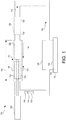
- FIG. 1 illustrates a system for pumping a fluid, according to an example.
- the SDMFP 100 consists of one or more actuators 102, an actuator drive 104 (micro-solenoid, piezo-transducer, linear DC micro-motor, etc.) and a housing 106.
- the actuator drive 104 can include a micro-solenoid.
- a piezo-transducer can deliver high pressures and forces but the stroke can be short.
- a force/displacement converters can be used (e.g., a lever) to deliver required action over the entire stroke length.
- the housing 106 extends along a length 116 defining an elongate interior 118.
- the actuator 102 disposed in the housing 106, conforming to the elongate interior 118.
- the pump 100 can be from around 30 millimeters in length, 15 millimeters in width and 15 millimeters in height. These dimensions can apply to the exterior of the housing 106.
- a circulation loop 108 can include various conduits, manifolds and the like.
- the pumped flow 110 is caused by the actuator 120 oscillating in housing 106. The oscillation occurs at a rate differential between movement in a first or forward direction or stroke 112 versus movement in a second or return direction or stroke 114 opposite the first stroke 112.
- the actuator 102 includes a plurality of lumens 120.
- Each of the lumens 120 has a length extending substantially parallel to the elongate interior 118, such as to a surface or axis thereof.
- Each of the lumens 120 measures from around 10 to 200 micrometers across.
- Examples lumens can include microtubes or micro-channels disposed in the actuator 102.
- At least one of the plurality of lumens has a rectilinear shape in cross-section.
- At least one of the plurality of lumens has a circular shape in cross-section.
- the plurality of lumens can be distributed according to a regular pattern.
- the plurality of lumens can be distributed according to a random pattern, as illustrated.
- the plurality of lumens comprise from around 60% to 80% of a cross-sectional area of the actuator.
- the plurality of lumens comprise from around 78.5% of a cross-sectional area of the actuator.
- fluid such as liquid can be pulled through the lumens and thus through the housing 106.
- the return stroke 114 can be faster than the forward stroke 112.
- the return stroke is from 100 to 1000 times faster. Accordingly, movement in the return direction can be at a frequency that can be from around 100 to around 1000 times faster than movement in the forward direction. Movement in the return direction can be around 1000 hertz, and movement in the forward direction can be at around 10 hertz.
- the movement in the return direction can be around 10000 hertz, and movement in the forward direction can be at around 10 hertz.
- the movement in the return direction can be around 2000-5000 hertz, and movement in the forward direction can be at from around 20-50 hertz.
- Simple harmonic period motion can windmill the fluid.
- the movement in the forward direction can be a forward distance from 0.5 to 5 millimeters in 100 to 500 milliseconds, and movement in the return direction can be a return distance 0.5 to 5 millimeters in 1 to 2 milliseconds.
- the forward distance and the return distance can be substantially equivalent.
- the actuator can be configured to move in the forward direction at an average speed of around 30-50 millimeters per second.
- the average and/or instantaneous speeds in forward and return stroke of the wall can vary. These can depend on specific conditions desired in an application.
- the fluid can have an "effective" speed that is the complex interaction of the wall/interface/boundary speeds, vorticity diffusion, shear stresses, geometry, etc.
- the average wall velocities can be 10 mm/s in a forward stroke and 1000 mm/s (1 m/s) in a return stroke.
- Different designs will have various "effective" fluid speeds ranging from about 5 to 50 mm/s.
- the wall speeds in forward and return stroke can vary from about 5 to 5000 mm/s.
- the forward motion 112 can be caused by, for example, applying a 5V current to a micro-solenoid current at several mA. Other voltages can be used.
- the current can travel through the coil and force the actuator 102 forward, such as in response to magnetic fields interactions.
- Reverse motion can be achieved by high reverse-current in micro-solenoid. Reverse motion can be achieved by adverse liquid pressure action.
- Very fast return motion can create partial or full slip on the boundary. This can be caused by simultaneous actuator impulse heating of the thin inner wall layers, which can involve hyperbolic heat transfer.
- the Stokes penetration layer can be shorter than in a forward stroke and pump leakage can be minimized.
- the size of the lumens is important.
- the diffusive momentum transfer can decay exponentially from the generating wall. Therefore the range of friction forces can be quite short. This is at least partially why such pumping concept do not work (or can be inefficient) on macro scales such as in tubes, larger than 1 millimeter. Additionally, micro-tubes with less than 1-5 micrometers can have partial slip associated with them (molecular effects in general) and can be more difficult and expensive to manufacture.
- the lumens 120 can be 10 to 200 micrometers in diameter.
- the SDMFP can for a part of a system 124.
- the system can include a heat exchanger 122.
- the heat exchanger 122 can include an emission portion, such as fins.
- An internal portion of the heat exchanger 122 can be in fluid communication with the circulation loop 108.
- An external portion 132 of heat emission portion 122, thermally conductive with the internal portion 130, can be configured to exchange heat with a cold source, such as an airflow, for example created by a fan.
- the system 124 can include at least one heat exchanger 126 to exchange heat with an external object 128.
- the heat exchanger 126 can include an internal portion 136 in fluid communication with the circulation loop 108 or forming a part thereof, and configured to exchange heat via an external portion 134 in communication with a heat source 128, such as an integrated circuit.
- the integrated circuit forms a part of a computer comprising a random access memory.
- the integrated circuit forms a part of a computer comprising an embedded processor.
- a thermally conductive material such as grease can form part of the interface between the heat exchanger 126 and the heat source 128.
- the present subject matter extends to embodiments in which heat is exchanged from and to the external object 128. Embodiments in which heat transfer to the heat source is endothermic for the heat source can add heat to the heat exchanger 122.
- a flow rate sensor 138 can sense a flow rate of the flow 110.
- the pump 100 can be configured to adjust the oscillation in association with the flow rate.
- a temperature sensor 140 can sense a temperature.
- the pump 100 can be configured to adjust the oscillation in association with the temperature.
- a differential pressure sensor 142 can sense a differential pressure.
- the pump 100 can be configured to adjust the oscillation in association with the differential pressure.
- FIG. 2A illustrates an elevated perspective view of an actuator 200 of a pump, according to an example.
- FIG. 2B is a cross-sectional view of an actuator 202, according to an example.
- FIG. 2B illustrates a housing 208, that can house the actuator 202.
- the actuator 200 comprises a shear-driven micro-fluidic pump, cylindrical ("SDMFPC"), in which the actuator 200 has a cylindrical shape.
- SDMFPC shear-driven micro-fluidic pump
- the lumens illustrated represent an arbitrary sample of what can be hundreds of lumens, and thus examples are not limited to the location or size of the lumens, which are representative illustrations.
- Geometries other than cylindrical can be used. Examples include, but are not limited to, rectilinear shapes, triangular shapes, elliptical shapes, and the like.
- the actuator cylinder 210 can be made of plastic or metal. The material can be relatively easy to form. Example forming processes for the actuator cylinder 210 include, but are not limited to, machining, such as by drilling, micro-molding, micro-casting and the like.
- FIG. 2B illustrates a pump motor stator 212.
- the stator 212 can form a part of a micro-solenoid in which the actuator 202 is the rotor.
- a ring of ferrous material such as soft iron or another material can be attached to the outer surface of the cylinder 214.
- a plurality of lumens 206, optionally hundreds of small tubes (e.g., micro-tubes or ⁇ -tubes) can be formed in the cylinder 214.
- Example forming processes for the lumens include, but are not limited to, drilling, such as laser or ultrasound drilling, injection-molding, micro-casting and the like.
- the actuator 202 can have diameter of 2, 5, or 10 mm and length of 5-20 mm. Each micro-tube has the same length of, say 10 mm, and the diameter of 25 (SHP), 50 (HP), 100 (MP), to 200 (LP) micrometers.
- An SDMFPC with diameter of 5 mm and length of 10 mm can include 500 micro-tubes of 100 micrometer diameter.
- the forward stroke can be 2 mm achieved in 100 milliseconds (10 Hz) resulting in an average forward speed of 20 mm/s.
- the average forward speed can be 14 mm/s.
- the average speed of the fluid for medium pressure gradients can be 11 mm/s.
- the return stoke can be the same length (e.g., 2 mm) but of shorter duration, e.g., 1 millisecond (1000 Hz or 1 kHz).
- the average return speed can be thus 2 m/s (2000 mm/s).
- the average return speed can be 1.4 m/s (1400 mm/s).
- the return stroke can affect or only affect a thin layer and cause return flow while the bulk fluid can still be moving forward.
- the cycle-averaged forward speed can be around 10 mm/s for moderate pressure gradients.
- Super high-performance (SHP) SDMFPs can have average forward speed in the range 30-50 mm/s.
- FIG. 3 is a cross-sectional view of an actuator assembly 300 including a plurality of guiding rails, according to an example.
- An outer housing 302 can house a micro-solenoid coil 304.
- the micro-solenoid coil can be sandwiched between the outer housing 302 and an inner housing 312.
- the inner housing can form a housing for the actuator 310.
- a small clearance e.g. of about 10-20 micrometers, can be defined between the plunger/actuator and the inner water-tight housing.
- the actuator 310 can include lumens such as micro-tubes 308.
- the cross sectional view illustrates guiding rails 306 that can provide for pump actuation into an out of the page, while resisting rotation around an axis into the page.
- FIG. 4 is the top view of an actuator assembly 400 including a plurality of guiding rails, according to an example.
- An outer housing 402 can house a micro-solenoid coil 404.
- the micro-solenoid coil can be sandwiched between the outer housing 402 and an inner housing 412.
- the inner housing can form a housing for the actuator 410.
- a small clearance 406, e.g. of about 10-20 micrometers, can be defined between the plunger/actuator and the inner water-tight housing.
- the actuator 410 can include lumens such as micro-tubes 408.
- the cross sectional view illustrates an absence of guiding rails. Accordingly, the actuator 410 is free to rotate around an axis into the page.
- the actuator 410 can be magnetic.
- the actuator 410 can be formed as a composite including a magnetic portion, such as a coating or jacket.
- FIG. 5 is a side view of an actuator drive 500, according to an example.
- the actuator 504 is slideably disposed in inner housing 512.
- a micro-solenoid coil 502 can be coiled around it the inner housing 512.
- the current direction and strength in the coil can be controlled by microcontroller to deliver slow forward and fast return movements.
- the controller can coordinate the operation of a voltage source 510 to provide DC voltage.
- the polarity of the voltage source 510 can be reversed to encourage pumping.
- the current 508 can be reversible. Accordingly, SDMFP examples can be bi-directional, in that they can reverse pumping direction, such as by changing actuation.
- FIG. 6 is a schematic of a multiple actuator pump, according to an example.
- a SDMFP for SHP Super High Pressure
- the actuators 602 can move in unison.
- FIG. 7A is an elevated perspective view of an actuator 700 including annular and radial divisions, according to an example.
- FIG. 7B is a cross-sectional view of an actuator 700 including annular and radial divisions, according to an example.
- a shear-driven micro-fluidic pump, annular (“SDMFPA”), including an annular actuator 700 can be formed by several processes, including, but not limited to, micro-machining, injection micro-molding and micro-casting.
- the material can be plastic or metal.
- Thin co-axial cylinders 702 intersect radial spreaders 704 to form thin curved slits 706 that can be used to transport fluid by the periodic non-harmonic excitations disclosed herein.
- the geometric dimensions of the shear-driven micro-fluidic pump, cylindrical can be used as in the SDMFPA.
- the SDMFPA can offer a higher luminal cross-sectional area when compared to the SDMFPC.
- the same slit heights e.g. 50, 100 or 200 micrometers can be formed around a circumference of the SDMFPA. Slits can vary in height from ring to ring.
- the actuator can be comprised of co-axial cylinders intersected by radial spreaders defining a plurality of curved slits.
- Each of the slits can have a slit-bisecting arc length of from 25-200 micrometers.
- Each of the slits can have a radial width of around 50 micrometers.
- At least one of the co-axial cylinders can be around 50 micrometers in thickness.
- the SDMFPA can define less solid surface, which can lead to lower pumping effort.
- the co-axial design of the SDMFPA can be used for high flow ("HF") with medium pressure ("MP") or low-pressure ("LP") performance.
- the actuator can be manufactured inexpensively.
- the thickness of the co-axial cylinders can be constant (e.g., 50 micrometers; e.g. a foil such as a metal foil).
- the SDMFPA can be easier to manufacture by injection micro-molding and micro-casting than drilling hundreds of micro-tubes. If a micro-solenoid is used as a driving principle, a stator can surround an actuator housing, and the actuator 700 can be made of thin cylindrical metal foils that comprise a rotor.
- the size of the channel/duct can be tenfold Stokes' penetration depth. Accordingly, some or most of the fluid does not experience the presence of the oscillating wall.
- the diffusion length can be on the order of the geometrical length of the actuator and all the fluid can move in-phase with the moving boundary.
- the forward stroke can be relatively slow and pull the fluid forward.
- the return stroke can be very fast and affects the thin layer close to wall. Effectively such non-harmonic (period) oscillations can result in net forward flow (pumping).
- the smaller the duct scale the faster it can be to move in forward and return stroke. Simultaneously, a smaller duct can be used to overcome higher backpressures.
- High-performance (“HP”) and super high-performance (“SHP”) ducts such as micro-tubes, can have small diameters (10 to 50 micrometers) and can be used in forward stroke with the frequency of 20-50 Hz and in return stroke of 2-5 kHz.
- the driving frequencies in the forward and return stroke for the given micro-tube diameter can be determined in association with a determined liquid kinematic viscosity.
- the fluid velocity in the core region can be less than 80% of the average wall velocity.
- the return stroke frequency can be very high.
- the interior fluid velocity e.g., at the center of the tube does not decrease below 10% of the maximum wall velocity.
- the return Reynolds number can be 100 times larger than forward Re-number on average.
- the flow can remain substantially laminar. Turbulence onset and large amplitude entrance effects of Tolmien-Schlichting waves can have little or no time to develop and can be quickly suppressed if they do develop.
- the Reynolds number is 1000 (SHP) in rapid return, the flow can remain laminar.
- the time for oscillation period can be about 2-orders of magnitude shorter than for diffusive transport in return stroke. Accordingly, the momentum from the wall resists penetration deep into fluid during the return stroke.
- FIG. 8 can be a schematic showing valve function, according to an example.
- An SDMFP can include a microvalve.
- a Gurney-type flap that resembles a leaf-spring with a small tab at the end can be used to amplify hydrodynamic or inertial forces as desired.
- An elastic flap 802 can close in actuator return stroke. The closing can be contributed to or caused by pressure and inertial forces.
- the tab 804 In the slow forward stroke the tab 804 can create hydrodynamic forces and the moments that can overcome spring effect and open it fully against the upper wall in the rectangular channel, e.g. as shown in FIG. 9 .
- a leaf-spring hysteresis can be used to improve pumping action. Very high pressure can be achieved by combining shear and valve action.
- Some SDMFP designs do not include microvalves. When Gurney-flap type microvalves are used larger channel dimensions can be used, and higher pressures can be achieved.
- FIG. 9 is an elevated perspective view of a rectangular plunger including flaps, according to an example. It shows a first channel 902 and a second channel 904, with a center plate 906 that can be coupled to one or more valves.
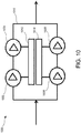
- FIG. 10 can be a schematic of a pump configuration including two pumps and two actuators, according to an example.
- SDMFPs can be arranged to work in serial-parallel combination and powered by one or more drivers as shown with an example in FIG. 10 .
- the pump 1002 can be a first pump, and a second pump 1006 can be coupled to the circulation loop 1010 in parallel with the first pump.
- a third pump 1004 can be coupled to the circulation loop 1010 in series with the first pump 1002.
- a fourth pump 1008 can be coupled to the circulation loop 1010 in parallel with the third pump 1006. For certain operations one driver can be shut-down.
- SDMFPs can be integrated into one housing (say, L30 x W15 x H15 mm).
- Two SDMFP 1002, 1004 can be in a series can be powered by one micro-actuator 1012 such as a micro-solenoid.
- the other parallel two SDMFPs 1006, 1008 can be powered by a second micro-actuator 1014.
- An entire side can be shut for a part of a heat transfer operation when a power consumption reduction is desired.
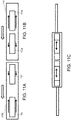
- FIG. 11A illustrates a first mode of operation of a two actuator pumping system, according to an example.
- FIG. 11B illustrates a second mode of operation of a two actuator pumping system, according to an example.
- FIG. 11C illustrates a two actuators aligned in series to pump fluid, according to an example.
- Actuators 1102-1108 of a first pump 1108 and a second pump 1110 can move in unison or against each other.
- actuators can work in serial/parallel combination to increase head and/or flow rates (capacity). For very high pressures an actuator can be split into several smaller cylinders to enhance entrance flow effects in reverse strokes.
- Certain examples split the actuator into several shorter components to improve tube entrance effects in return stroke, which can reduce pump leakage.
- the adverse pressure gradient that can be overcome is 4,000 Pa/m (4 kPa/m or 40 mbar/m).
- the pumping effort of 10 mm actuator can be 40 Pa.
- the effective wall speed can be 15 mm/s
- the maximum pressure gradient can be 192 kPa/m or 1920 Pa (1.92 kPa or 19.2 mbar) maximum pumping effort.
- Two actuators in a series can deliver around 4,000 Pa (4 kPa or 40 mbar) pumping effort.
- a Super-High-Pressure SDMFPC can deliver 10,000-100,000 Pa (10-100 kPa or 100 to 1000 mbar) alone and the micro-tubes can be about 25-30 micrometers in diameter.
- the cylinder actuator length can be 10, 15, or 20 mm long split into several shorter cylinders of 3-5 mm length and free space of 3 mm in between.
- Such a pump can be longer (15 to 20 mm) but can produce improved pressures at improved volume flow rates.
- One of the reasons to split the cylinder into several smaller ones is to enhance the constructive tube flow entry effects. By splitting the pump into parallel-serial combination once can reduce the effect of high peak power using large actuator drives.
- FIG. 12 illustrates a rectified-sine (absolute sine) form illustrating a quick return driving waveform, according to an example.
- Non-harmonic pumping can be important, in combination with shear forces, to the efficacy of SDMFP pumping.
- Designing driving waveforms can be important in SDMFP efficient operation.
- One waveform can be rectified sine-function (absolute sine) followed by a rapid inverted sine as shown.
- the area under the curve can be equal for both curves (distance can be the same and the motion can be periodic).
- the return stroke velocity (and associated Reynolds number) can be about 100 times faster in return stroke than in forward stroke.
- FIG. 13 illustrates a square-type driving waveform, according to an example.
- the SDMFP plunger can coast between rapid acceleration and decelerations.
- FIG. 14 illustrates behavior of a non-Newtonian fluid, according to an example.
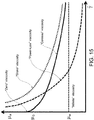
- FIG. 15 illustrates behavior of a non-Newtonian fluid, according to an example.
- Hydraulic SDMFP performance characteristics can be enhanced if a shear-thinning (pseudo-plastic) time-independent non-Newtonian fluid is used as a working fluid.
- An illustration of basic time-independent non-Newtonian (or Generalized Newtonian) fluids is shown in FIGS 14-15 .
- One result is enhanced plug like flow of the fluid interior. This can be especially beneficial in certain applications. For example, in pumping blood in coronary arteries where shear rates can be small enough that shear-thickening becomes important, an SDMFP can be perform desirably.
- Drag reduction techniques using Moffat-vortices principle fish-scales micro-geometry, impulse heating and special thin layers can increase friction drag in one direction and lower it in another, which can benefit performance.
- Coatings on the actuator can increase shear in one direction and decrease it in another thus additionally increasing volumetric efficiency.
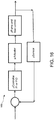
- FIG. 16 illustrates a negative feedback control loop, according to an example.
- the SDMFP can respond well to continuous control.
- a simple feedback control 1600 can be designed to adjust pump working parameters (e.g., one or both of flow rate and pumping effort).
- Adaptive control can be used.
- micro-sensors can be embedded in a micro-pump and can provide necessary information to microcontroller to regulate pump operating set-point.
- Micro-actuators can deliver high torque/force in the return stroke and can be power-limited.
- the forward stroke can require much less power but can be energy-limited.
- the stroke length can be 0.5 to 5 mm and that has to be taken into consideration.
- Most likely actuator candidates can be (1) Micro-solenoid.
- a system can be remotely controlled.
- FIG. 17 illustrates a method of using a pump, according to an example.
- Examples can include a method for heat exchange between a heat source and a heat exchanger.
- the method can include affixing the heat exchanger to the heat source, with the heat exchanger thermally communicative with the heat source.
- the method can include pumping a liquid through the heat exchanger by oscillating an actuator including a plurality of microlumens with a rate differential between strokes.
- This can include pumping a liquid through the heat exchanger, at a determined flow rate and liquid pressure, by oscillating an actuator in a pump housing extending along a length defining an elongate interior, the actuator conforming to the elongate interior, the actuator including a plurality of lumens, each having a length extending substantially parallel to the elongate interior, each from around 20 to 200 micrometers across, wherein an oscillation takes place with a rate differential between movement in a first direction versus movement in a second direction opposite the first direction.
- the method can include exchanging heat between the heat exchanger and the heat source.
- Pumping can include pumping the liquid at a minimum of 80% of an actuator speed. Pumping can include maintaining a Reynolds number of the liquid while the actuator can be moving in the first direction to be 1/100th the Reynolds number of the liquid while the actuator can be moving in the second direction. Pumping can include sensing a flow rate and adjusting the oscillation in association with the flow rate. Pumping can include sensing a differential pressure and adjusting the oscillation in association with the differential pressure. Pumping can include sensing a temperature and adjusting the oscillation in association with the temperature. Pumping the liquid can include pumping at a flow rate of up to 100 milliliters per second, at a pressure of up to 40 kilopascals.
- the apparatuses, systems and methods discloser herein can be used in fluid cooling.
- the SDMFP has by its nature a wide dynamic range, i.e., flow rate and net pressure head can be varied over several orders of magnitude. This can be something that can be not available with other commercially available micro-pumps.
- the forward and return stroke frequencies (periods) can be adjusted over a wide range to deliver variable oscillations dynamics. Due to the high-bandwidth of the return stroke a lot of space can be left for accurate flow and effort control with high resolution. Adding another SDMFP in a circulation system we can offer flow rates up to 100 mL/min and total effort up to of 40 kPa (400 mbar). On the other hand the same SDMFP can provide accurate low rates of only several ⁇ L/min.
- External size can be about 5 to 30 mm in length and 5 to 10 mm in depth and 10-15 mm in width and it would be used mostly in liquid-cooling systems.
- a microfluidic system that employs pumping can use this pump.
- Aerospace applications can include use as pressurized fuel delivery for micro-jet engines and/or liquid propellant for micro-rocket engines.
- Example applications can include micro-thrusters for micro-satellites, for example for orbital, attitude control, and/or main propulsion.
- a CPU can release 100 W Peak-Power to be absorbed in micro-channel convective heat exchanger, transported, and rejected in heat sink.
- a heat-sink in existing microelectronics includes a finned metallic heat exchanger air-cooled (forced convection) by the computer fan/ventilator.
- the single-phase liquid convection-conduction based removal of heat through micro-channels embedded in multi-core CPU can use about 30-60 mL/min of water as a coolant and the pressure drop in an entire cooling loop can be on the order of 15,000-500,000 Pa (150-5000 mbar).
- dynamic viscosity can be 10 -3 Pa sec (1 mPas or 1 cP) and density can be 10 3 kg/m 3 .
- Coolant can enter a stacked micro-channels or CPU-embedded heat exchanger pool at, say 40 °C. With phase change water warmed up to 100 °C (e.g., at 1 bar absolute pressure) the phase-change can take place to produce vapor-liquid mixture (bubbly or slug flow).
- the SDMFP can deliver the effort at designed flow rate (e.g., capacity).
- the total micro-pump efficiency can be 10%-30%.
- the power requirements for a shear-driven micro-fluidic pump can be on the order of ten milli-Watts.
- the forces necessary to move the actuator can be on the order of ten milli-Newton. Accordingly the microsolenoids and piezoelectric force transducers can power SDMFPs.
- the SDMFP can be installed in vascular channels (body) directly.
- Many biomedical and medical applications can benefit from a use of highly efficient, low-power consumption, safe shear-driven micro-fluidic pump design. Whether it embedded design SD-MFP assisting human blood circulation in systemic or coronary hemodynamics for people with cardio-vascular difficulties/diseases or delivering on-demand insulin for diabetic patients, the shear-driven micro-fluidic pump exhibits efficient performance.
- the pumps can be very small to be surgically inserted into vascular channels (arteries, arterioles, etc.). Since SDMFP concept can be relatively efficient it can operate for years on small batteries. For example, for 10 mW pumping power and with low 20% total efficiency (e.g., pumping leakage and actuator efficiency) an average 50 mW of electric power is used by the pump (e.g., 10 mA with 5V source, e.g. a DC computer CPU voltage). If the SDMFP works 10 hours at maximum power per day (e.g., average power over 24 hours normalized), then for one year (365 days) the pump can consume 182.5 W-hr (36.5 A-hr) or 0.1825 kW-hr/year.
- the peak power required to accelerate the actuator on the order of several G in return stroke can be on the order of 100 mW.
- Capacitors can be used to store electrical energy necessary for quick discharge and peak power.
- the pump actuating cylinders resemble hollow devices, and are thus light, but have mass that can experience a large number of cycles. For example, a pump can work over a period of 5 years.
- the forward stroke can repeat 2-10 times per second, resulting in around 800 million relatively slow forward strokes followed by rapid return strokes (e.g., of a duration of 500-2000 ⁇ s). Additionally, the entire embedded micro-control can be remotely adjusted.
- the shear-driven concept can be efficient on the microscales (e.g., 10 to 500 micrometers with no microvalves).
- the invention is directed to an apparatus to pump a fluid according
- Method examples described herein can be machine or computer-implemented at least in part. Some examples can include a computer-readable medium or machine-readable medium encoded with instructions operable to configure an electronic device to perform methods as described in the above examples.
- An implementation of such methods can include code, such as microcode, assembly language code, a higher-level language code, or the like. Such code can include computer readable instructions for performing various methods. The code can form portions of computer program products. Further, in an example, the code can be tangibly stored on one or more volatile, non-transitory, or non-volatile tangible computer-readable media, such as during execution or at other times.
- Examples of these tangible computer-readable media can include, but are not limited to, hard disks, removable magnetic disks, removable optical disks (e.g., compact disks and digital video disks), magnetic cassettes, memory cards or sticks, random access memories (RAMs), read only memories (ROMs), and the like.
Landscapes
- Engineering & Computer Science (AREA)
- General Engineering & Computer Science (AREA)
- Mechanical Engineering (AREA)
- Microelectronics & Electronic Packaging (AREA)
- Physics & Mathematics (AREA)
- Thermal Sciences (AREA)
- Theoretical Computer Science (AREA)
- Human Computer Interaction (AREA)
- General Physics & Mathematics (AREA)
- Reciprocating Pumps (AREA)
- Micromachines (AREA)
- Lubricants (AREA)
Applications Claiming Priority (2)
| Application Number | Priority Date | Filing Date | Title |
|---|---|---|---|
| US201361770250P | 2013-02-27 | 2013-02-27 | |
| IT000161A ITTO20130161A1 (it) | 2013-02-27 | 2013-02-27 | Pompa micro-fluidica a forza di taglio |
Publications (3)
| Publication Number | Publication Date |
|---|---|
| EP2772648A2 EP2772648A2 (en) | 2014-09-03 |
| EP2772648A3 EP2772648A3 (en) | 2015-05-06 |
| EP2772648B1 true EP2772648B1 (en) | 2018-04-11 |
Family
ID=48366463
Family Applications (1)
| Application Number | Title | Priority Date | Filing Date |
|---|---|---|---|
| EP14156825.3A Active EP2772648B1 (en) | 2013-02-27 | 2014-02-26 | Shear driven micro-fluidic pump |
Country Status (3)
| Country | Link |
|---|---|
| US (2) | US9528503B2 (it) |
| EP (1) | EP2772648B1 (it) |
| IT (1) | ITTO20130161A1 (it) |
Families Citing this family (17)
| Publication number | Priority date | Publication date | Assignee | Title |
|---|---|---|---|---|
| ITTO20130161A1 (it) | 2013-02-27 | 2014-08-28 | Aar Aerospace Consulting L L C | Pompa micro-fluidica a forza di taglio |
| DE102013017812B4 (de) * | 2013-10-25 | 2019-01-24 | Liebherr-Components Biberach Gmbh | Kühlvorrichtung für leistungselektronische Bauteile |
| TWI590571B (zh) * | 2014-12-08 | 2017-07-01 | 強生控制科技公司 | 可變速驅動器系統及冷卻系統 |
| US10136563B2 (en) * | 2015-06-25 | 2018-11-20 | International Business Machines Corporation | Active perforation for advanced server cooling |
| US9989049B2 (en) * | 2015-12-11 | 2018-06-05 | Funai Electric Co., Ltd. | Microfluidic pump |
| US10118696B1 (en) | 2016-03-31 | 2018-11-06 | Steven M. Hoffberg | Steerable rotating projectile |
| US11712637B1 (en) | 2018-03-23 | 2023-08-01 | Steven M. Hoffberg | Steerable disk or ball |
| US10823136B2 (en) * | 2018-04-27 | 2020-11-03 | Pliant Energy Systems Llc | Apparatuses, methods and systems for harnessing the energy of fluid flow to generate electricity or pump fluid |
| CN108897392A (zh) * | 2018-06-28 | 2018-11-27 | 郭锦明 | 一种便于移动的减震散热型计算机机箱 |
| GB2569417B (en) * | 2018-07-31 | 2020-06-17 | Ttp Ventus Ltd | Microfluidic drive system |
| US11152283B2 (en) | 2018-11-15 | 2021-10-19 | Hewlett Packard Enterprise Development Lp | Rack and row-scale cooling |
| US11015608B2 (en) | 2018-12-10 | 2021-05-25 | Hewlett Packard Enterprise Development Lp | Axial flow pump with reduced height dimension |
| WO2020212628A1 (es) * | 2019-04-18 | 2020-10-22 | Fundació Institut De Ciències Fotòniques | Aparato fluídico para interrogación óptica de microorganismos individuales |
| JP7759107B2 (ja) * | 2019-11-29 | 2025-10-23 | マルコム バリー ジェームズ | 流体相変化熱管理装置および方法 |
| CN112105226B (zh) * | 2020-09-10 | 2022-03-01 | 杭州电子科技大学 | 内置螺旋式液体通道的大功率芯片散热系统及其散热方法 |
| KR20230133323A (ko) * | 2021-01-29 | 2023-09-19 | 도날드슨 컴파니, 인코포레이티드 | 순환 유동 장치 |
| US20260013074A1 (en) * | 2024-07-02 | 2026-01-08 | Cgg Services Sas | Fluid immersion cooling assembly |
Family Cites Families (16)
| Publication number | Priority date | Publication date | Assignee | Title |
|---|---|---|---|---|
| JPS4997904A (it) * | 1973-01-26 | 1974-09-17 | ||
| US4348946A (en) * | 1977-02-03 | 1982-09-14 | Karl Eickmann | Radial piston machine with free--floating piston and piston--shoe assemblies |
| US4210409A (en) * | 1978-05-19 | 1980-07-01 | Child Laboratories Inc. | Solenoid operating pump |
| US4447195A (en) * | 1982-02-22 | 1984-05-08 | Air Products And Chemicals, Inc. | High pressure helium pump for liquid or supercritical gas |
| SU1208286A1 (ru) * | 1984-05-21 | 1986-01-30 | Предприятие П/Я М-5939 | Поршень дл двигател внутреннего сгорани |
| US5833440A (en) * | 1995-02-10 | 1998-11-10 | Berling; James T. | Linear motor arrangement for a reciprocating pump system |
| US5509792A (en) * | 1995-02-27 | 1996-04-23 | Pumpworks, Inc. | Electromagnetically driven reciprocating pump with fluted piston |
| ATE407096T1 (de) * | 2002-05-16 | 2008-09-15 | Micronit Microfluidics Bv | Verfahren zur herstellung eines mikrofluidischen bauteiles |
| WO2005060593A2 (en) * | 2003-12-10 | 2005-07-07 | Purdue Research Foundation | Micropump for electronics cooling |
| JP2009525882A (ja) * | 2006-02-07 | 2009-07-16 | コーニンクレッカ フィリップス エレクトロニクス エヌ ヴィ | 複数の刺激に反応する微小流体工学のためのアクチュエータ素子 |
| US7299770B2 (en) * | 2006-04-10 | 2007-11-27 | Thorpe Douglas G | Evaporative in-cylinder cooling |
| CN103153839B (zh) * | 2010-08-20 | 2014-08-13 | 格瑞克明尼苏达有限公司 | 用于同步线性泵系统的方法 |
| CN103429348B (zh) * | 2011-01-21 | 2016-03-09 | 拜奥-多特公司 | 具有纵向变换器和可替换毛细管的压电分配器 |
| ITCO20120027A1 (it) * | 2012-05-16 | 2013-11-17 | Nuovo Pignone Srl | Attuatore elettromagnetico e dispositivo di conservazione d¿inerzia per un compressore alternativo |
| ITTO20130161A1 (it) | 2013-02-27 | 2014-08-28 | Aar Aerospace Consulting L L C | Pompa micro-fluidica a forza di taglio |
| JP6159815B2 (ja) * | 2013-10-16 | 2017-07-05 | 株式会社小松製作所 | 摺動部品、摺動部品の製造方法および摺動部品の製造装置 |
-
2013
- 2013-02-27 IT IT000161A patent/ITTO20130161A1/it unknown
- 2013-07-22 US US13/947,993 patent/US9528503B2/en not_active Expired - Fee Related
-
2014
- 2014-02-26 EP EP14156825.3A patent/EP2772648B1/en active Active
-
2016
- 2016-12-21 US US15/387,567 patent/US9810207B2/en not_active Expired - Fee Related
Non-Patent Citations (1)
| Title |
|---|
| None * |
Also Published As
| Publication number | Publication date |
|---|---|
| US9528503B2 (en) | 2016-12-27 |
| EP2772648A3 (en) | 2015-05-06 |
| ITTO20130161A1 (it) | 2014-08-28 |
| US9810207B2 (en) | 2017-11-07 |
| EP2772648A2 (en) | 2014-09-03 |
| US20140240916A1 (en) | 2014-08-28 |
| US20170096990A1 (en) | 2017-04-06 |
Similar Documents
| Publication | Publication Date | Title |
|---|---|---|
| US9810207B2 (en) | Method and shear-driven micro-fluidic pump | |
| Akram et al. | A theoretical investigation on the heat transfer ability of water-based hybrid (Ag–Au) nanofluids and Ag nanofluids flow driven by electroosmotic pumping through a microchannel | |
| Prakash et al. | Peristaltic pumping of magnetic nanofluids with thermal radiation and temperature-dependent viscosity effects: modelling a solar magneto-biomimetic nanopump | |
| Yuan et al. | The pumping effect of growing and collapsing bubbles in a tube | |
| Frampton et al. | The scaling of acoustic streaming for application in micro-fluidic devices | |
| Li et al. | Study on the performance of a designed annular piezoelectric microjet for active lubrication of space bearing | |
| DeCourtye et al. | Analysis of viscous micropumps and microturbines | |
| Blanchard et al. | Single-disk and double-disk viscous micropumps | |
| Tong et al. | Piezoelectric micropump cooler for high-power electronic cooling | |
| Haider et al. | Impact of heat transfer on peristaltic flow of nanofluid and its applications in real world problems | |
| Wen et al. | Application of a valveless impedance pump in a liquid cooling system | |
| Blanchard et al. | Miniature single-disk viscous pump (single-DVP), performance characterization | |
| Bataineh et al. | 2D Navier–Stokes simulations of microscale viscous pump with slip flow | |
| Glockner et al. | Thermocapillary control of microfluidic transport with a stationary cyclic heat source | |
| Naterer | Adaptive surface microprofiling for microfluidic energy conversion | |
| Akbar et al. | Advanced FEM analysis of thermal transport and flow dynamics in Au-Fe2O3 blood-based hybrid nanoliquids for biomedical applications: insights into tissue engineering: NS Akbar et al. | |
| Bian et al. | Investigation on the influence of design parameters of streamline flow tubes on pump performance | |
| Nguyen et al. | A compound droplet undergoing thermocapillary migration passing through a constricted tube | |
| Tabak et al. | Simulation-based analysis of flow due to traveling-plane-wave deformations on elastic thin-film actuators in micropumps | |
| Lai et al. | System modeling and characterization of enhanced valveless micropumps | |
| Zhu et al. | Design and Dynamic Characteristics Research of Fishmouth Shaped Baffle Ferrofluid Micro-Pump | |
| CN103706413A (zh) | 微流控相变汽泡微泵阀及其方法 | |
| Lu et al. | Flow dynamical behaviors and characteristics of aligned and staggered viscous pumps | |
| Moffatt | Singularities in fluid dynamics and their resolution | |
| Blanchard et al. | Performance and development of a miniature rotary shaft pump |
Legal Events
| Date | Code | Title | Description |
|---|---|---|---|
| PUAI | Public reference made under article 153(3) epc to a published international application that has entered the european phase |
Free format text: ORIGINAL CODE: 0009012 |
|
| 17P | Request for examination filed |
Effective date: 20140226 |
|
| AK | Designated contracting states |
Kind code of ref document: A2 Designated state(s): AL AT BE BG CH CY CZ DE DK EE ES FI FR GB GR HR HU IE IS IT LI LT LU LV MC MK MT NL NO PL PT RO RS SE SI SK SM TR |
|
| AX | Request for extension of the european patent |
Extension state: BA ME |
|
| PUAL | Search report despatched |
Free format text: ORIGINAL CODE: 0009013 |
|
| AK | Designated contracting states |
Kind code of ref document: A3 Designated state(s): AL AT BE BG CH CY CZ DE DK EE ES FI FR GB GR HR HU IE IS IT LI LT LU LV MC MK MT NL NO PL PT RO RS SE SI SK SM TR |
|
| AX | Request for extension of the european patent |
Extension state: BA ME |
|
| RIC1 | Information provided on ipc code assigned before grant |
Ipc: F04B 19/00 20060101AFI20150330BHEP Ipc: F04B 43/04 20060101ALI20150330BHEP |
|
| R17P | Request for examination filed (corrected) |
Effective date: 20151103 |
|
| RAX | Requested extension states of the european patent have changed |
Extension state: ME Extension state: BA Payment date: 20151103 |
|
| RBV | Designated contracting states (corrected) |
Designated state(s): AL AT BE BG CH CY CZ DE DK EE ES FI FR GB GR HR HU IE IS IT LI LT LU LV MC MK MT NL NO PL PT RO RS SE SI SK SM TR |
|
| RIC1 | Information provided on ipc code assigned before grant |
Ipc: H05K 7/20 20060101ALI20170823BHEP Ipc: F04B 19/00 20060101AFI20170823BHEP Ipc: F04B 35/04 20060101ALI20170823BHEP Ipc: F04B 17/04 20060101ALI20170823BHEP Ipc: F04B 53/08 20060101ALI20170823BHEP Ipc: G06F 1/20 20060101ALI20170823BHEP Ipc: B23P 15/26 20060101ALI20170823BHEP Ipc: F04B 43/04 20060101ALI20170823BHEP |
|
| GRAP | Despatch of communication of intention to grant a patent |
Free format text: ORIGINAL CODE: EPIDOSNIGR1 |
|
| STAA | Information on the status of an ep patent application or granted ep patent |
Free format text: STATUS: GRANT OF PATENT IS INTENDED |
|
| INTG | Intention to grant announced |
Effective date: 20171009 |
|
| GRAS | Grant fee paid |
Free format text: ORIGINAL CODE: EPIDOSNIGR3 |
|
| GRAA | (expected) grant |
Free format text: ORIGINAL CODE: 0009210 |
|
| STAA | Information on the status of an ep patent application or granted ep patent |
Free format text: STATUS: THE PATENT HAS BEEN GRANTED |
|
| AK | Designated contracting states |
Kind code of ref document: B1 Designated state(s): AL AT BE BG CH CY CZ DE DK EE ES FI FR GB GR HR HU IE IS IT LI LT LU LV MC MK MT NL NO PL PT RO RS SE SI SK SM TR |
|
| AX | Request for extension of the european patent |
Extension state: BA |
|
| REG | Reference to a national code |
Ref country code: GB Ref legal event code: FG4D |
|
| REG | Reference to a national code |
Ref country code: CH Ref legal event code: EP |
|
| REG | Reference to a national code |
Ref country code: AT Ref legal event code: REF Ref document number: 988329 Country of ref document: AT Kind code of ref document: T Effective date: 20180415 |
|
| REG | Reference to a national code |
Ref country code: IE Ref legal event code: FG4D |
|
| REG | Reference to a national code |
Ref country code: DE Ref legal event code: R096 Ref document number: 602014023579 Country of ref document: DE |
|
| REG | Reference to a national code |
Ref country code: NL Ref legal event code: MP Effective date: 20180411 |
|
| REG | Reference to a national code |
Ref country code: LT Ref legal event code: MG4D |
|
| PG25 | Lapsed in a contracting state [announced via postgrant information from national office to epo] |
Ref country code: NL Free format text: LAPSE BECAUSE OF FAILURE TO SUBMIT A TRANSLATION OF THE DESCRIPTION OR TO PAY THE FEE WITHIN THE PRESCRIBED TIME-LIMIT Effective date: 20180411 |
|
| PG25 | Lapsed in a contracting state [announced via postgrant information from national office to epo] |
Ref country code: NO Free format text: LAPSE BECAUSE OF FAILURE TO SUBMIT A TRANSLATION OF THE DESCRIPTION OR TO PAY THE FEE WITHIN THE PRESCRIBED TIME-LIMIT Effective date: 20180711 Ref country code: PL Free format text: LAPSE BECAUSE OF FAILURE TO SUBMIT A TRANSLATION OF THE DESCRIPTION OR TO PAY THE FEE WITHIN THE PRESCRIBED TIME-LIMIT Effective date: 20180411 Ref country code: LT Free format text: LAPSE BECAUSE OF FAILURE TO SUBMIT A TRANSLATION OF THE DESCRIPTION OR TO PAY THE FEE WITHIN THE PRESCRIBED TIME-LIMIT Effective date: 20180411 Ref country code: ES Free format text: LAPSE BECAUSE OF FAILURE TO SUBMIT A TRANSLATION OF THE DESCRIPTION OR TO PAY THE FEE WITHIN THE PRESCRIBED TIME-LIMIT Effective date: 20180411 Ref country code: SE Free format text: LAPSE BECAUSE OF FAILURE TO SUBMIT A TRANSLATION OF THE DESCRIPTION OR TO PAY THE FEE WITHIN THE PRESCRIBED TIME-LIMIT Effective date: 20180411 Ref country code: AL Free format text: LAPSE BECAUSE OF FAILURE TO SUBMIT A TRANSLATION OF THE DESCRIPTION OR TO PAY THE FEE WITHIN THE PRESCRIBED TIME-LIMIT Effective date: 20180411 Ref country code: BG Free format text: LAPSE BECAUSE OF FAILURE TO SUBMIT A TRANSLATION OF THE DESCRIPTION OR TO PAY THE FEE WITHIN THE PRESCRIBED TIME-LIMIT Effective date: 20180711 Ref country code: FI Free format text: LAPSE BECAUSE OF FAILURE TO SUBMIT A TRANSLATION OF THE DESCRIPTION OR TO PAY THE FEE WITHIN THE PRESCRIBED TIME-LIMIT Effective date: 20180411 |
|
| PG25 | Lapsed in a contracting state [announced via postgrant information from national office to epo] |
Ref country code: RS Free format text: LAPSE BECAUSE OF FAILURE TO SUBMIT A TRANSLATION OF THE DESCRIPTION OR TO PAY THE FEE WITHIN THE PRESCRIBED TIME-LIMIT Effective date: 20180411 Ref country code: HR Free format text: LAPSE BECAUSE OF FAILURE TO SUBMIT A TRANSLATION OF THE DESCRIPTION OR TO PAY THE FEE WITHIN THE PRESCRIBED TIME-LIMIT Effective date: 20180411 Ref country code: LV Free format text: LAPSE BECAUSE OF FAILURE TO SUBMIT A TRANSLATION OF THE DESCRIPTION OR TO PAY THE FEE WITHIN THE PRESCRIBED TIME-LIMIT Effective date: 20180411 Ref country code: GR Free format text: LAPSE BECAUSE OF FAILURE TO SUBMIT A TRANSLATION OF THE DESCRIPTION OR TO PAY THE FEE WITHIN THE PRESCRIBED TIME-LIMIT Effective date: 20180712 |
|
| REG | Reference to a national code |
Ref country code: AT Ref legal event code: MK05 Ref document number: 988329 Country of ref document: AT Kind code of ref document: T Effective date: 20180411 |
|
| PG25 | Lapsed in a contracting state [announced via postgrant information from national office to epo] |
Ref country code: PT Free format text: LAPSE BECAUSE OF FAILURE TO SUBMIT A TRANSLATION OF THE DESCRIPTION OR TO PAY THE FEE WITHIN THE PRESCRIBED TIME-LIMIT Effective date: 20180813 |
|
| REG | Reference to a national code |
Ref country code: DE Ref legal event code: R097 Ref document number: 602014023579 Country of ref document: DE |
|
| PG25 | Lapsed in a contracting state [announced via postgrant information from national office to epo] |
Ref country code: EE Free format text: LAPSE BECAUSE OF FAILURE TO SUBMIT A TRANSLATION OF THE DESCRIPTION OR TO PAY THE FEE WITHIN THE PRESCRIBED TIME-LIMIT Effective date: 20180411 Ref country code: DK Free format text: LAPSE BECAUSE OF FAILURE TO SUBMIT A TRANSLATION OF THE DESCRIPTION OR TO PAY THE FEE WITHIN THE PRESCRIBED TIME-LIMIT Effective date: 20180411 Ref country code: SK Free format text: LAPSE BECAUSE OF FAILURE TO SUBMIT A TRANSLATION OF THE DESCRIPTION OR TO PAY THE FEE WITHIN THE PRESCRIBED TIME-LIMIT Effective date: 20180411 Ref country code: AT Free format text: LAPSE BECAUSE OF FAILURE TO SUBMIT A TRANSLATION OF THE DESCRIPTION OR TO PAY THE FEE WITHIN THE PRESCRIBED TIME-LIMIT Effective date: 20180411 Ref country code: CZ Free format text: LAPSE BECAUSE OF FAILURE TO SUBMIT A TRANSLATION OF THE DESCRIPTION OR TO PAY THE FEE WITHIN THE PRESCRIBED TIME-LIMIT Effective date: 20180411 Ref country code: RO Free format text: LAPSE BECAUSE OF FAILURE TO SUBMIT A TRANSLATION OF THE DESCRIPTION OR TO PAY THE FEE WITHIN THE PRESCRIBED TIME-LIMIT Effective date: 20180411 |
|
| PLBE | No opposition filed within time limit |
Free format text: ORIGINAL CODE: 0009261 |
|
| STAA | Information on the status of an ep patent application or granted ep patent |
Free format text: STATUS: NO OPPOSITION FILED WITHIN TIME LIMIT |
|
| PG25 | Lapsed in a contracting state [announced via postgrant information from national office to epo] |
Ref country code: IT Free format text: LAPSE BECAUSE OF FAILURE TO SUBMIT A TRANSLATION OF THE DESCRIPTION OR TO PAY THE FEE WITHIN THE PRESCRIBED TIME-LIMIT Effective date: 20180411 Ref country code: SM Free format text: LAPSE BECAUSE OF FAILURE TO SUBMIT A TRANSLATION OF THE DESCRIPTION OR TO PAY THE FEE WITHIN THE PRESCRIBED TIME-LIMIT Effective date: 20180411 |
|
| 26N | No opposition filed |
Effective date: 20190114 |
|
| PG25 | Lapsed in a contracting state [announced via postgrant information from national office to epo] |
Ref country code: SI Free format text: LAPSE BECAUSE OF FAILURE TO SUBMIT A TRANSLATION OF THE DESCRIPTION OR TO PAY THE FEE WITHIN THE PRESCRIBED TIME-LIMIT Effective date: 20180411 |
|
| REG | Reference to a national code |
Ref country code: DE Ref legal event code: R119 Ref document number: 602014023579 Country of ref document: DE |
|
| REG | Reference to a national code |
Ref country code: CH Ref legal event code: PL |
|
| GBPC | Gb: european patent ceased through non-payment of renewal fee |
Effective date: 20190226 |
|
| PG25 | Lapsed in a contracting state [announced via postgrant information from national office to epo] |
Ref country code: LU Free format text: LAPSE BECAUSE OF NON-PAYMENT OF DUE FEES Effective date: 20190226 Ref country code: MC Free format text: LAPSE BECAUSE OF FAILURE TO SUBMIT A TRANSLATION OF THE DESCRIPTION OR TO PAY THE FEE WITHIN THE PRESCRIBED TIME-LIMIT Effective date: 20180411 |
|
| REG | Reference to a national code |
Ref country code: BE Ref legal event code: MM Effective date: 20190228 |
|
| REG | Reference to a national code |
Ref country code: IE Ref legal event code: MM4A |
|
| PG25 | Lapsed in a contracting state [announced via postgrant information from national office to epo] |
Ref country code: LI Free format text: LAPSE BECAUSE OF NON-PAYMENT OF DUE FEES Effective date: 20190228 Ref country code: CH Free format text: LAPSE BECAUSE OF NON-PAYMENT OF DUE FEES Effective date: 20190228 |
|
| PG25 | Lapsed in a contracting state [announced via postgrant information from national office to epo] |
Ref country code: DE Free format text: LAPSE BECAUSE OF NON-PAYMENT OF DUE FEES Effective date: 20190903 Ref country code: GB Free format text: LAPSE BECAUSE OF NON-PAYMENT OF DUE FEES Effective date: 20190226 Ref country code: IE Free format text: LAPSE BECAUSE OF NON-PAYMENT OF DUE FEES Effective date: 20190226 |
|
| PG25 | Lapsed in a contracting state [announced via postgrant information from national office to epo] |
Ref country code: BE Free format text: LAPSE BECAUSE OF NON-PAYMENT OF DUE FEES Effective date: 20190228 Ref country code: FR Free format text: LAPSE BECAUSE OF NON-PAYMENT OF DUE FEES Effective date: 20190228 |
|
| PG25 | Lapsed in a contracting state [announced via postgrant information from national office to epo] |
Ref country code: TR Free format text: LAPSE BECAUSE OF FAILURE TO SUBMIT A TRANSLATION OF THE DESCRIPTION OR TO PAY THE FEE WITHIN THE PRESCRIBED TIME-LIMIT Effective date: 20180411 |
|
| PG25 | Lapsed in a contracting state [announced via postgrant information from national office to epo] |
Ref country code: MT Free format text: LAPSE BECAUSE OF NON-PAYMENT OF DUE FEES Effective date: 20190226 |
|
| PG25 | Lapsed in a contracting state [announced via postgrant information from national office to epo] |
Ref country code: CY Free format text: LAPSE BECAUSE OF FAILURE TO SUBMIT A TRANSLATION OF THE DESCRIPTION OR TO PAY THE FEE WITHIN THE PRESCRIBED TIME-LIMIT Effective date: 20180411 |
|
| PG25 | Lapsed in a contracting state [announced via postgrant information from national office to epo] |
Ref country code: IS Free format text: LAPSE BECAUSE OF FAILURE TO SUBMIT A TRANSLATION OF THE DESCRIPTION OR TO PAY THE FEE WITHIN THE PRESCRIBED TIME-LIMIT Effective date: 20180811 |
|
| PG25 | Lapsed in a contracting state [announced via postgrant information from national office to epo] |
Ref country code: HU Free format text: LAPSE BECAUSE OF FAILURE TO SUBMIT A TRANSLATION OF THE DESCRIPTION OR TO PAY THE FEE WITHIN THE PRESCRIBED TIME-LIMIT; INVALID AB INITIO Effective date: 20140226 |
|
| PG25 | Lapsed in a contracting state [announced via postgrant information from national office to epo] |
Ref country code: MK Free format text: LAPSE BECAUSE OF FAILURE TO SUBMIT A TRANSLATION OF THE DESCRIPTION OR TO PAY THE FEE WITHIN THE PRESCRIBED TIME-LIMIT Effective date: 20180411 |