EP2772569A1 - Method for manufacturing porous aluminum foil, porous aluminum foil, positive electrode collector for electricity storage device, electrode for electricity storage device, and electricity storage device - Google Patents
Method for manufacturing porous aluminum foil, porous aluminum foil, positive electrode collector for electricity storage device, electrode for electricity storage device, and electricity storage device Download PDFInfo
- Publication number
- EP2772569A1 EP2772569A1 EP12844049.2A EP12844049A EP2772569A1 EP 2772569 A1 EP2772569 A1 EP 2772569A1 EP 12844049 A EP12844049 A EP 12844049A EP 2772569 A1 EP2772569 A1 EP 2772569A1
- Authority
- EP
- European Patent Office
- Prior art keywords
- aluminum foil
- foil
- porous aluminum
- plating solution
- positive electrode
- Prior art date
- Legal status (The legal status is an assumption and is not a legal conclusion. Google has not performed a legal analysis and makes no representation as to the accuracy of the status listed.)
- Granted
Links
Images


Classifications
-
- H—ELECTRICITY
- H01—ELECTRIC ELEMENTS
- H01M—PROCESSES OR MEANS, e.g. BATTERIES, FOR THE DIRECT CONVERSION OF CHEMICAL ENERGY INTO ELECTRICAL ENERGY
- H01M4/00—Electrodes
- H01M4/02—Electrodes composed of, or comprising, active material
- H01M4/04—Processes of manufacture in general
- H01M4/0438—Processes of manufacture in general by electrochemical processing
- H01M4/0469—Electroforming a self-supporting electrode; Electroforming of powdered electrode material
-
- C—CHEMISTRY; METALLURGY
- C25—ELECTROLYTIC OR ELECTROPHORETIC PROCESSES; APPARATUS THEREFOR
- C25D—PROCESSES FOR THE ELECTROLYTIC OR ELECTROPHORETIC PRODUCTION OF COATINGS; ELECTROFORMING; APPARATUS THEREFOR
- C25D1/00—Electroforming
- C25D1/04—Wires; Strips; Foils
-
- C—CHEMISTRY; METALLURGY
- C25—ELECTROLYTIC OR ELECTROPHORETIC PROCESSES; APPARATUS THEREFOR
- C25D—PROCESSES FOR THE ELECTROLYTIC OR ELECTROPHORETIC PRODUCTION OF COATINGS; ELECTROFORMING; APPARATUS THEREFOR
- C25D1/00—Electroforming
- C25D1/20—Separation of the formed objects from the electrodes with no destruction of said electrodes
-
- C—CHEMISTRY; METALLURGY
- C25—ELECTROLYTIC OR ELECTROPHORETIC PROCESSES; APPARATUS THEREFOR
- C25D—PROCESSES FOR THE ELECTROLYTIC OR ELECTROPHORETIC PRODUCTION OF COATINGS; ELECTROFORMING; APPARATUS THEREFOR
- C25D3/00—Electroplating: Baths therefor
- C25D3/02—Electroplating: Baths therefor from solutions
- C25D3/42—Electroplating: Baths therefor from solutions of light metals
- C25D3/44—Aluminium
-
- H—ELECTRICITY
- H01—ELECTRIC ELEMENTS
- H01G—CAPACITORS; CAPACITORS, RECTIFIERS, DETECTORS, SWITCHING DEVICES, LIGHT-SENSITIVE OR TEMPERATURE-SENSITIVE DEVICES OF THE ELECTROLYTIC TYPE
- H01G11/00—Hybrid capacitors, i.e. capacitors having different positive and negative electrodes; Electric double-layer [EDL] capacitors; Processes for the manufacture thereof or of parts thereof
- H01G11/66—Current collectors
- H01G11/68—Current collectors characterised by their material
-
- H—ELECTRICITY
- H01—ELECTRIC ELEMENTS
- H01G—CAPACITORS; CAPACITORS, RECTIFIERS, DETECTORS, SWITCHING DEVICES, LIGHT-SENSITIVE OR TEMPERATURE-SENSITIVE DEVICES OF THE ELECTROLYTIC TYPE
- H01G11/00—Hybrid capacitors, i.e. capacitors having different positive and negative electrodes; Electric double-layer [EDL] capacitors; Processes for the manufacture thereof or of parts thereof
- H01G11/66—Current collectors
- H01G11/70—Current collectors characterised by their structure
-
- H—ELECTRICITY
- H01—ELECTRIC ELEMENTS
- H01M—PROCESSES OR MEANS, e.g. BATTERIES, FOR THE DIRECT CONVERSION OF CHEMICAL ENERGY INTO ELECTRICAL ENERGY
- H01M4/00—Electrodes
- H01M4/02—Electrodes composed of, or comprising, active material
- H01M4/64—Carriers or collectors
- H01M4/66—Selection of materials
- H01M4/661—Metal or alloys, e.g. alloy coatings
-
- Y—GENERAL TAGGING OF NEW TECHNOLOGICAL DEVELOPMENTS; GENERAL TAGGING OF CROSS-SECTIONAL TECHNOLOGIES SPANNING OVER SEVERAL SECTIONS OF THE IPC; TECHNICAL SUBJECTS COVERED BY FORMER USPC CROSS-REFERENCE ART COLLECTIONS [XRACs] AND DIGESTS
- Y02—TECHNOLOGIES OR APPLICATIONS FOR MITIGATION OR ADAPTATION AGAINST CLIMATE CHANGE
- Y02E—REDUCTION OF GREENHOUSE GAS [GHG] EMISSIONS, RELATED TO ENERGY GENERATION, TRANSMISSION OR DISTRIBUTION
- Y02E60/00—Enabling technologies; Technologies with a potential or indirect contribution to GHG emissions mitigation
- Y02E60/10—Energy storage using batteries
-
- Y—GENERAL TAGGING OF NEW TECHNOLOGICAL DEVELOPMENTS; GENERAL TAGGING OF CROSS-SECTIONAL TECHNOLOGIES SPANNING OVER SEVERAL SECTIONS OF THE IPC; TECHNICAL SUBJECTS COVERED BY FORMER USPC CROSS-REFERENCE ART COLLECTIONS [XRACs] AND DIGESTS
- Y02—TECHNOLOGIES OR APPLICATIONS FOR MITIGATION OR ADAPTATION AGAINST CLIMATE CHANGE
- Y02E—REDUCTION OF GREENHOUSE GAS [GHG] EMISSIONS, RELATED TO ENERGY GENERATION, TRANSMISSION OR DISTRIBUTION
- Y02E60/00—Enabling technologies; Technologies with a potential or indirect contribution to GHG emissions mitigation
- Y02E60/13—Energy storage using capacitors
Definitions
- the present invention relates to a method for producing a porous aluminum foil which can be used, for example, as a positive electrode current collector for electrical storage devices such as lithium ion secondary batteries and supercapacitors (electrical double-layer capacitors, redox capacitors, lithium ion capacitors, etc.), a porous aluminum foil produced by the production method, a positive electrode current collector for electrical storage devices comprising the porous aluminum foil, an electrode for electrical storage devices comprising the positive electrode current collector for electrical storage devices, and an electrical storage device comprising the electrode for electrical storage devices.
- a positive electrode current collector for electrical storage devices such as lithium ion secondary batteries and supercapacitors (electrical double-layer capacitors, redox capacitors, lithium ion capacitors, etc.)
- a porous aluminum foil produced by the production method
- a positive electrode current collector for electrical storage devices comprising the porous aluminum foil
- an electrode for electrical storage devices comprising the positive electrode current collector for electrical storage devices
- an electrical storage device comprising the electrode for electrical storage devices.
- lithium ion secondary batteries which have high energy density and whose discharge capacity does not significantly decrease, have been used for a power source for mobile tools such as mobile phones and laptop computers.
- mobile tools such as mobile phones and laptop computers.
- supercapacitors having high energy density such as electrical double-layer capacitors, redox capacitors, and lithium ion capacitors, has been increasingly expanding, and there is a demand for a further increase in their energy density.
- An electrical storage device such as the lithium ion secondary battery or the supercapacitor, has a structure in which, for example, a positive electrode, a negative electrode, and a separator made of a polyolefin or the like between them are arranged in an organic electrolytic solution containing a fluorine-containing compound, such as LiPF 6 or NR 4 •BF 4 (R is an alkyl group), as an electrolyte.
- a fluorine-containing compound such as LiPF 6 or NR 4 •BF 4 (R is an alkyl group
- the positive electrode includes a positive electrode active material, such as LiCoO 2 (lithium cobalt oxide) or active carbon, and a positive electrode current collector
- the negative electrode includes a negative electrode active material, such as graphite or active carbon, and a negative electrode current collector, and, with respect to the shape, the electrodes are each obtained by applying the active material to the surface of the current collector and forming the same into a sheet.
- the electrodes are each subjected to high voltage and also immersed in the highly corrosive organic electrolytic solution that contains a fluorine-containing compound. Accordingly, materials for the positive electrode current collector, in particular, are required to have excellent electrical conductivity together with excellent corrosion resistance.
- LiMn 2 O 4 lithium manganese oxide
- LiFePO 4 lithium iron phosphate
- LiCoO 2 generally has a smaller particle size than LiCoO 2 , and therefore, it is difficult to apply these materials on an aluminum foil to be used as a positive electrode current collector with a high adhesion, unless the surface of the aluminum foil is subjected to any surface treatment or surface processing.
- Patent Document 1 A method of roughening a surface of an aluminum foil through a chemical treatment such as etching is thus proposed in Patent Document 1 as a method for enhancing the adhesion between an aluminum foil and a positive electrode active material.
- Patent Document 1 A method for enhancing the adhesion between an aluminum foil and a positive electrode active material.
- a method of making an aluminum foil porous by subjecting the foil to a mechanical processing such as punching is proposed.
- Patent Document 1 JP-A-2001-189238
- the method of roughening a surface of an aluminum foil through a chemical treatment such as etching has a problem that a step for roughening a surface of the foil is required after the production of the foil, a problem that it is difficult to ensure a uniformity of the foil thickness, and a problem that etching makes the foil thin to cause a reduction in its strength.
- the method of making an aluminum foil porous by subjecting the foil to a mechanical processing such as punching has a problem that a step for making the foil porous is required after the production of the foil, a problem that the foil is torn due to the mechanical processing or a protrusion called burr which may cause short circuit of the electrode is formed on the edge of the pore, and a problem that it is difficult to form fine pores.
- an object of the present invention is to provide a novel method for producing a porous aluminum foil which can be used, for example, as a positive electrode current collector for electrical storage devices, a porous aluminum foil produced by the production method, a positive electrode current collector for electrical storage devices comprising the porous aluminum foil, an electrode for electrical storage devices comprising the positive electrode current collector for electrical storage devices, and an electrical storage device comprising the electrode for electrical storage devices.
- the present inventor has conducted extensive research on the aluminum electroplating technology.
- the electrodeposition potential of aluminum is lower than the potential for generating hydrogen, and it may thus be impossible to electrodeposit aluminum from an aqueous solution.
- a non-aqueous plating solution (without water as a solvent) has been used as a plating solution for electroplating of aluminum, and it has been believed that water has to be eliminated as far as possible since water contained in a plating solution is a factor that inhibits the deposition of aluminum, and prevents the formation of a uniform aluminum film on a surface of a substrate.
- the present inventor thought that a porous aluminum film could be formed on a surface of a substrate, by taking advantage of the adverse effect of water contained in a plating solution on the formation of a uniform aluminum film to thereby partially inhibit the deposition of aluminum on the surface of the substrate, and that a porous aluminum foil could be obtained by separating the film from the substrate.
- the object of the present invention could be achieved by controlling a water content in a plating solution to an appropriate amount.
- a method for producing a porous aluminum foil of the present invention accomplished based on the above findings is, as defined in claim 1, characterized in that a porous aluminum film is formed on a surface of a substrate by electrolysis using a plating solution containing at least (1) a dialkyl sulfone, (2) an aluminum halide, and (3) a nitrogen-containing compound, and having a water content of 100 to 2000 ppm, and then the film is separated from the substrate.
- a production method as defined in claim 2 is characterized in that in the production method according to claim 1, the nitrogen-containing compound is at least one selected from the group consisting of an ammonium halide, a hydrogen halide salt of a primary amine, a hydrogen halide salt of a secondary amine, a hydrogen halide salt of a tertiary amine, and a quaternary ammonium salt represented by the general formula: R 1 R 2 R 3 R 4 N•X (R 1 to R 4 independently represent an alkyl group and are the same as or different from one another, and X represents a counteranion for the quaternary ammonium cation).
- the nitrogen-containing compound is at least one selected from the group consisting of an ammonium halide, a hydrogen halide salt of a primary amine, a hydrogen halide salt of a secondary amine, a hydrogen halide salt of a tertiary amine, and a quaternary ammonium salt represented by the general formula:
- a production method as defined in claim 3 is characterized in that in the production method according to claim 1, the porous aluminum foil obtained is subjected to a heat treatment.
- a production method as defined in claim 4 is characterized in that in the production method according to claim 3, the heat treatment is performed at 80 to 550°C.
- a production method as defined in claim 5 is characterized in that in the production method according to claim 1, the dialkyl sulfone is dimethyl sulfone.
- a porous aluminum foil of the present invention is, as defined in claim 6, characterized by having a crystal orientation such that the ratio of the X-ray diffraction intensity of the (111) plane to the X-ray diffraction intensities of other crystal planes is 2.5 or more with respect to a surface of the foil, and having a porosity of 1 to 70%.
- a porous aluminum foil of the present invention is, as defined in claim 7, characterized by being produced by the production method of claim 1.
- a positive electrode current collector for electrical storage devices of the present invention is, as defined in claim 8, characterized by comprising the porous aluminum foil of claim 6 or 7.
- An electrode for electrical storage devices of the present invention is, as defined in claim 9, characterized by comprising an electrode active material supported on the porous aluminum foil of claim 6 or 7.
- An electrical storage device of the present invention is, as defined in claim 10, characterized by comprising the electrode for electrical storage devices of claim 9.
- the method for producing a porous aluminum foil of the present invention it is possible to produce a porous aluminum foil which can be used, for example, as a positive electrode current collector for electrical storage devices, with a fewer number of steps without a step of making an aluminum foil porous after the production of the foil. It is also possible to produce a porous aluminum foil having fine pores which is difficult to be formed by a mechanical processing. Furthermore, the present invention provides a porous aluminum foil produced by the production method of the present invention, a positive electrode current collector for electrical storage devices comprising the porous aluminum foil, an electrode for electrical storage devices comprising the positive electrode current collector for electrical storage devices, and an electrical storage device comprising the electrode for electrical storage devices.
- a method for producing a porous aluminum foil of the present invention is characterized in that a porous aluminum film is formed on a surface of a substrate by electrolysis using a plating solution containing at least (1) a dialkyl sulfone, (2) an aluminum halide, and (3) a nitrogen-containing compound, and having a water content of 100 to 2000 ppm, and then the film is separated from the substrate.
- dialkyl sulfone to be contained in the plating solution used in the method for producing a porous aluminum foil of the present invention examples include those having a C 1-6 alkyl group (straight or branched), such as dimethyl sulfone, diethyl sulfone, dipropyl sulfone, dihexyl sulfone, and methylethyl sulfone. In terms of excellent electrical conductivity, availability, and the like, it is preferable to use dimethyl sulfone.
- Examples of the aluminum halide as a solute which is an aluminum source for forming an aluminum film on a surface of a substrate by electrolysis include aluminum chloride and aluminum bromide.
- an anhydride as the aluminum halide.
- a hydrate may be used to utilize water molecules held in the substance as water contained in the plating solution.
- the nitrogen-containing compound means a compound having at least one nitrogen atom in one molecule.
- Suitable examples of a usable nitrogen-containing compound include an ammonium halide, a hydrogen halide salt of a primary amine, a hydrogen halide salt of a secondary amine, a hydrogen halide salt of a tertiary amine, and a quaternary ammonium salt represented by the general formula: R 1 R 2 R 3 R 4 N•X (R 1 to R 4 independently represent an alkyl group and are the same as or different from one another, and X represents a counteranion for the quaternary ammonium cation), which compounds impart to an aluminum film formed on a surface of a substrate by electrolysis a ductility which facilitates the separation of the film from the surface of the substrate.
- These nitrogen-containing compounds may be used alone or as a mixture of two or more thereof.
- ammonium halide examples include ammonium chloride and ammonium bromide.
- examples of the primary to tertiary amines include those having a C 1-6 alkyl group (straight or branched), such as methylamine, dimethylamine, trimethylamine, ethylamine, diethylamine, triethylamine, propylamine, dipropylamine, tripropylamine, hexylamine, and methylethylamine.
- hydrogen halide examples include hydrogen chloride and hydrogen bromide.
- Examples of the alkyl group represented by R 1 to R 4 in the quaternary ammonium salt represented by the general formula: R 1 R 2 R 3 R 4 N•X include C 1-6 alkyl groups (straight or branched), such as a methyl group, an ethyl group, a propyl group, and a hexyl group.
- X may be a halide ion such as a chlorine ion, a bromine ion, or an iodine ion, or may also be BF 4 - , PF 6 - , or the like, for example.
- Specific examples of the compound include tetramethylammonium chloride, tetramethylammonium bromide, tetramethylammonium iodide, and tetraethylammonium tetrafluoroborate.
- particularly preferred examples of the nitrogen-containing compound include hydrochlorides of tertiary amines, such as trimethylamine hydrochloride.
- the proportions of a dialkyl sulfone, an aluminum halide, and a nitrogen-containing compound added are preferably such that, for example, per 10 mol of dialkyl sulfone, the amount of aluminum halide is 1.5 to 4.0 mol, more preferably 2.0 to 3.5 mol, and the amount of nitrogen-containing compound is 0.01 to 2.0 mol, more preferably 0.05 to 1.5 mol.
- the amount of aluminum halide added is less than 1.5 mol per 10 mol of dialkyl sulfone, this may cause the darkening of the aluminum film formed (a phenomenon called burning) or reduce the film formation efficiency.
- the solution resistance of the resulting plating solution may be so high that the plating solution may generate heat and decompose.
- the amount of nitrogen-containing compound added is less than 0.01 mol per 10 mol of dialkyl sulfone, the addition may be unlikely to achieve its effects, that is, effects such as the improvement of the film formation rate owing to the achievement of a plating treatment at a high applied current density based on the improved electrical conductivity of the plating solution, the purity increase or ductility improvement in the aluminum film, etc.
- aluminum when it is more than 2.0 mol, aluminum may not be deposited due to an essential change in the composition of the plating solution.
- the above composition of the plating solution used in the method for producing a porous aluminum foil of the present invention is according to a composition of a plating solution that is suitable for the production of an aluminum foil and is proposed by the present inventor in WO2011-001932 .
- a characteristic point of the plating solution used in the method for producing a porous aluminum foil of the present invention is in that water, which inhibits the formation of a uniform aluminum film on a surface of a substrate and therefore has been eliminated as far as possible from a plating solution, is allowed to be intentionally contained in an amount of 100 to 2000 ppm.
- the reason why the water content is defined to 100 to 2000 ppm is as follows. That is, when the water content is less than 100 ppm, water contained in the plating solution may be so small that the deposition of aluminum on a surface of a substrate is hardly inhibited, whereby a porous aluminum film may not be formed on the surface of the substrate.
- water contained in the plating solution may be so large that a phenomenon that the aluminum film formed contains a large amount of impurities, a phenomenon that the film is darkened (a phenomenon called burning), or the like may occur.
- the water content in a plating solution is preferably 200 to 1900 ppm.
- the method for adjusting the water content in a plating solution is not particularly limited as long as the method results in the water content of 100 to 2000 ppm after the adjustment. The adjustment can be performed by adding a given amount of water to a plating solution prepared, or by adding a given amount of water in advance to a substance which becomes a component of a plating solution and then preparing the plating solution.
- a substance which becomes a component of a plating solution contains water due to its storage condition or the like
- water contained in the substance may be utilized
- a substance which becomes a component of a plating solution is a hydrate
- water held by the substance may be utilized, to adjust the water content.
- the electroplating conditions may be such that, for example, the temperature of the plating solution is 80 to 110°C, and the applied current density is 2 to 15 A/dm 2 .
- the lower limit of the temperature of the plating solution should be determined in consideration of the melting point of the plating solution. It is preferably 85°C, and more preferably 95°C (when the temperature is below the melting point of the plating solution, the plating solution solidifies, whereby a plating treatment cannot be performed anymore).
- the temperature of the plating solution is more than 110°C, this may accelerate the reaction between the aluminum film formed on the surface of the substrate and the plating solution, which increases the incorporation of impurities into the aluminum film, resulting in reduced purity.
- the film formation efficiency may decrease.
- the applied current density is preferably 3 to 12 A/dm 2 .
- a significant advantage of the plating solution used in the method for producing a porous aluminum foil of the present invention is that a stable plating treatment is possible even when a current density of 10 A/dm 2 or more is applied, and thus the improvement of the film formation rate can be achieved.
- the plating treatment time depends on the desired thickness of the aluminum foil, the temperature of the plating solution, the applied current density, and the like, but is usually 1 to 90 minutes (preferably 1 to 30 minutes considering production efficiency).
- the substrate for forming a porous aluminum film may be, for example, a stainless steel plate, a titanium plate, an aluminum plate, a nickel plate, or the like.
- the surface of the substrate is made as smooth as possible by mirror finishing, for example.
- a porous aluminum film formed on a surface of a substrate in the present invention has a characteristic in that it can be easily separated even without subjecting the substrate to such processing.
- the reason thereof is not necessarily clear, but is presumably related to the fact that upon the formation of a porous aluminum film on a surface of a substrate, the concentrations of S and Cl derived from a plating solution increase near the surface of the film that is in contact with the substrate.
- aluminum can be mentioned, for example.
- the porous aluminum film may be separated from the substrate batchwise, or, alternatively, it is also possible to perform the formation and separation of the porous aluminum film continuously using a cathode drum (e.g., JP-A-6-93490 ).
- a cathode drum e.g., JP-A-6-93490
- the thickness of the porous aluminum foil (the thickness of the porous aluminum film formed on the surface of the substrate) is preferably, for example, 3 to 200 ⁇ m.
- the thickness is less than 3 ⁇ m, the foil may not have a sufficient strength to be used as a current collector.
- the pores, even if once formed, may be directed to disappear due to further crystal growth of aluminum.
- the size and the shape are varied, but the size may be generally about from 1 to 500 ⁇ m, and typically from 3 to 50 ⁇ m.
- the size of a pore herein means the long diameter of a hole passing through the foil from the front side to the back side thereof.
- the porosity may be generally about 1 to 70%.
- the pore size and the porosity can be changed by adjusting the water content in the plating solution. As the water content in the plating solution increases, the pore size and the porosity tend to increase.
- a porous aluminum foil having pores having a size of 50 ⁇ m or less, for example, can be produced according to the method of the present invention. It is however difficult to produce a porous aluminum foil having such fine pores by a method in which a foil prepared in advance is subjected to a mechanical processing such as punching.
- a positive electrode active material When a positive electrode active material is applied on a surface of a porous aluminum foil having a pore size and a porosity as described above, the positive electrode active material enters the interior of the pores, and hence the adhesion between the foil and the positive electrode active material is increased, whereby the positive electrode active material can be supported strongly on the surface of the foil.
- the pore size is less than 1 ⁇ m, it may be smaller than the size of the particles of the positive electrode active material such that the pores may fail to contribute to the increase of the adhesion between the foil and the positive electrode active material.
- the foil when it is more than 500 ⁇ m, the foil may not have a sufficient strength to be used as a current collector.
- the porosity is less than 1%, the ratio of the pores relative to the foil may be so small that the pores may fail to contribute to the increase of the adhesion between the foil and the positive electrode active material.
- the foil may not have a sufficient strength to be used as a current collector.
- the porous aluminum foil obtained as described above may be subjected to a heat treatment.
- a heat treatment it is possible to avoid a problem that water remaining on the surface of the foil causes unstable electrochemical behavior of an electrical storage device in which the foil is used as a positive electrode current collector for the device, to thereby adversely affect the characteristics of the device.
- an advantageous effect such as removal of strain in the foil or improvement of tensile strength can be expected.
- the heat treatment of the aluminum foil may be performed at 80 to 550°C for 2 to 120 minutes in an atmosphere such as an ambient atmosphere, a reduced pressure atmosphere, or an inert gas atmosphere using argon gas or nitrogen gas, for example.
- the temperature of the heat treatment is less than 80°C, the effect of the heat treatment may not be sufficiently achieved.
- the aluminum foil approaches the melting point of aluminum (660°C), which may cause the softening of the foil.
- the heat treatment time is less than 2 minutes, the effect of the heat treatment may not be sufficiently achieved.
- productivity may be adversely affected.
- the temperature of the heat treatment is preferably 100 to 450°C, and more preferably 200 to 350°C.
- the heat treatment time is preferably 20 to 90 minutes.
- conductive particles such as carbonaceous particles may also be added to the plating solution used in the method for producing a porous aluminum foil of the present invention.
- the conductive particles dispersed and supported in the foil contribute to the reduction of the electrical surface resistance of the foil.
- the carbonaceous particles have excellent electrical conductivity with a carbon content of 90 mass% or more. Examples thereof include furnace black particles, acetylene black particles, carbon black particles, black lead particles, and graphite particles, as well as carbon nanotubes and carbon nanofibers.
- the size of carbonaceous particles (depending on the shape, "size” means grain size, diameter, fiber diameter, length, etc., and may also mean the size of an aggregate in the case where the particles are present as aggregates) is preferably 1 nm to 100 ⁇ m, more preferably 1 nm to 15 ⁇ m, and still more preferably 3 nm to 5 ⁇ m.
- size of carbonaceous particles is less than 1 nm, they may be unlikely to contribute to the reduction of the electrical surface resistance of the foil.
- it is more than 100 ⁇ m they may be difficult to uniformly disperse in the foil or the plating solution. In addition, it may be impossible to thin a positive electrode current collector.
- the size of the carbonaceous particles is 50% or less of the thickness of the foil.
- the form of the presence of carbonaceous particles dispersed and supported in a foil is not particularly limited. However, in order for the carbonaceous particles to effectively contribute to the reduction of the electrical surface resistance of the foil, it is preferable that at least some of the carbonaceous particles are protruded from the surface of the foil, for example, and thus exposed to the outside. In light of this, the size of carbonaceous particles may be greater than the thickness of the foil.
- the carbonaceous particles in order for the carbonaceous particles to be firmly supported in the foil, it is preferable that their size is 150% or less of the thickness of the foil.
- the amount of carbonaceous particles dispersed in the plating solution is preferably 1 ⁇ 10 -4 to 1 g per 100 mL of the plating solution. When the amount dispersed is less than 1 ⁇ 10 -4 g per 100 mL of the plating solution, it may be impossible for the carbonaceous particles to be dispersed and supported in an amount sufficient to contribute to the reduction of the electrical surface resistance of the foil (e.g., 0.01 to 3.0 mass% of the porous aluminum foil containing the carbonaceous particles dispersed and supported therein).
- the viscosity of the plating solution may be so high that electroplating may be difficult. It is preferable that the carbonaceous particles are dispersed in the plating solution while thoroughly stirring the plating solution so that the carbonaceous particles are uniformly dispersed in the solution and thus uniformly dispersed and supported in the foil. It is also possible to apply ultrasonic waves as required.
- the plating solution used in the method for producing a porous aluminum foil of the present invention has an advantage in that the dispersibility of carbonaceous particles is extremely excellent even without adding a dispersant to the plating solution or surface-treating carbonaceous particles to enhance the dispersibility of carbonaceous particles in the plating solution.
- the porous aluminum foil produced by the method of the present invention is a foil having a characteristic crystal orientation which has heretofore not been known and the (111) plane is preferentially oriented with respect to the surface of the foil.
- the ratio of the X-ray diffraction intensity of the (111) plane to the X-ray diffraction intensities of other crystal planes ((200), (220), (311), (222) planes, etc.) is 2.5 or more. This characteristic crystal orientation does not substantially vary even when the foil is subjected to a heat treatment.
- Dimethyl sulfone, aluminum chloride, andtrimethylamine hydrochloride as reagents were used to produce a porous aluminum foil according to the following procedure.
- Dimethyl sulfone had a water content of 109 ppm
- aluminum chloride had that of 40 ppm
- trimethylamine hydrochloride had that of 95 ppm (measured with Moisture Meter CA-100, manufactured by Mitsubishi Chemical Corporation; the same hereinafter).
- These three reagents were mixed under nitrogen gas flow in a molar ratio of dimethyl sulfone : aluminum chloride : trimethylamine hydrochloride of 10:3:0.01 and dissolved at 110°C, thereby preparing an aluminum electroplating solution.
- the water content in this plating solution was 200 ppm.
- This aluminum foil was subjected to a heat treatment in an ambient atmosphere at 300°C for 60 minutes.
- the thickness of the resulting aluminum foil was about 12 ⁇ m.
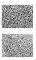
- the scanning electron microscope photographs (apparatus: VE-8800, manufactured by Keyence Corporation; the same hereinafter) of the front side (the side opposite to the side facing the titanium plate) and the back side (the side facing the titanium plate) of this aluminum foil are shown in Figs. 1 and 2 respectively.
- this aluminum foil was a porous foil having a large number of fine pores having a size of 20 ⁇ m or less, and the porosity thereof was about 30%.
- the porosity of the porous aluminum foil was determined by an image analysis of a scanning electron microscope photograph (magnification: ⁇ 100) of any 1 mm square view of the foil (the same hereinafter).
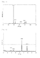
- the front side of this porous aluminum foil was measured for the X-ray diffraction peak using an X-ray diffractometer (D8 ADVANCE: manufactured by Bruker AXS, a ⁇ -20 method using CuK ⁇ ray as the X-ray; the same hereinafter).
- D8 ADVANCE manufactured by Bruker AXS, a ⁇ -20 method using CuK ⁇ ray as the X-ray; the same hereinafter.
- the result is shown in Fig. 3 .
- Fig. 3 As is clear from Fig.
- the crystal orientation was such that the (111) plane was preferentially oriented with respect to the surface of the foil, and the ratio of the X-ray diffraction intensity of the (111) plane to the X-ray diffraction intensity of the (200) plane (X-ray diffraction intensity of (111) plane/X-ray diffraction intensity of (200) plane) was a characteristic value of 7.7.
- the similar result was obtained in the measurement for the back side of the foil.
- the crystal orientation of this porous aluminum foil was quite different from that of the aluminum foil produced by rolling (an X-ray diffraction peak of a rolled aluminum foil having a thickness of 20 ⁇ m manufactured by Nippon Foil Mfg. Co., Ltd. is shown in Fig. 4 as a reference example).
- the porous aluminum foil obtained above was used as a positive electrode current collector for electrical storage devices.
- a slurry prepared by mixing lithium manganese oxide, acetylene black, and polyvinylidene fluoride in a weight ratio of 8:1:1 was applied using a doctor blade, followed by vacuum drying at 80°C for 24 hours to form a positive electrode active material layer on the surface of the foil.
- an electrode (positive electrode) for electrical storage devices having a total thickness of about 40 ⁇ m was produced.
- a cross-cut was formed on the thus obtained electrode, and then this electrode was immersed in an organic electrolyte solution obtained by dissolving lithium hexafluorophosphate in a mixture solvent of 1:1 volume ratio of ethylene carbonate (EC) and dimethyl carbonate (DMC) into a concentration of 1 mol/L (1 mol/L LiPF 6 / EC + DMC (1:1 by vol.)).
- EC ethylene carbonate
- DMC dimethyl carbonate
- the electrode was removed from the solution, roughly washed with water, and dried with hot-air drier. Subsequently, the adhesion between the foil and the positive electrode active material was evaluated by a tape separation test, and then a good adhesion was exhibited.
- FIG. 5 A scanning electronic microscopic photograph of the cross-section of the electrode is shown in Fig. 5 .
- a schematic view of the cross-section is shown in Fig. 6 .
- the positive electrode active material layer on the surface of the foil was formed such that the positive electrode active material entered the interior of a pore in the foil. It was confirmed that the pores in the foil contributed to the enhancement of the adhesion between the foil and the positive electrode active material.
- An electrical storage device which was fabricated using this electrode so as to have a configuration known per se had a desired performance.
- An electrode (positive electrode) for electrical storage devices was produced according to the same procedure as in Example 1 except for using the aluminum foil before the heat treatment in the ambient atmosphere at 300°C for 60 minutes in Example 1.
- This aluminum foil before the heat treatment was a porous foil having a structural features similar to that of the aluminum foil after the heat treatment (however, the ratio of the X-ray diffraction intensity of the (111) plane to the X-ray diffraction intensity of the (200) plane was 8.7, which was slightly higher than that after the heat treatment).
- the water content in this plating solution was 100 ppm.
- an aluminum film was formed on a surface of a titanium plate according to the same procedure as in Example 1 except that an applied current density was 10 A/dm 2 , and then the aluminum film was separated from the titanium plate to obtain an aluminum foil.
- This aluminum foil was subjected to a heat treatment in an ambient atmosphere at 300°C for 60 minutes.
- the thickness of the resulting aluminum foil was about 45 ⁇ m.
- This aluminum foil was a porous foil having a large number of fine pores having a size of 8 ⁇ m or less, and the porosity thereof was about 3%.
- the (111) plane was preferentially oriented with respect to the surface of the foil, similar to the crystal orientation of the porous aluminum foil of Example 1, and the ratio of the X-ray diffraction intensity of the (111) plane to the X-ray diffraction intensity of the (200) plane was a characteristic value of 5.0.
- the porous aluminum foil obtained above was used as a positive electrode current collector for electrical storage devices.
- a slurry prepared by mixing lithium iron phosphate, acetylene black, and polyvinylidene fluoride in a weight ratio of 9:0.5:0.5 was applied using a doctor blade, followed by vacuum drying at 80°C for 24 hours to form a positive electrode active material layer on the surface of the foil.
- an electrode (positive electrode) for electrical storage devices having a total thickness of about 70 ⁇ m was produced.
- the electrode was evaluated using an experimental apparatus shown in Fig. 7 according to the following procedure. An organic electrolyte solution 25 was poured in a container 24 in the experimental apparatus 20.
- the charge-discharge rate was set to 0.3C, 1C, 2C, or 3C (C means a charge-discharge rate.
- 0.3C means that one charge-discharge cycle is completed in 200 minutes
- 1C means that one charge-discharge cycle is completed in 1 hour
- 2C means that one charge-discharge cycle is completed in 30 minutes
- 3C means that one charge-discharge cycle is completed in 20 minutes).
- the discharge behaviors in the respective charge-discharge rate are shown in Fig. 8 (The horizontal axis shows discharge capacity and the vertical axis shows potential applied to the positive electrode). As is clear from Fig. 8 , although a higher charge-discharge rate generally leads to a lower discharge capacity, when using the positive electrode produced according to the above procedure, the decrease of the discharge capacity was relatively small.
- the discharge capacity at the charge-discharge rate of 0.3C was 148 Ah/kg, while the discharge capacity at the charge-discharge rate of 3C was 117 Ah/kg, and the reduction of the discharge capacity was suppressed to 25% or less. This is due to that the adhesion between the active material and the current collector was good and thus electrons were smoothly exchanged between the active material and the current collector, resulting in reduction of energy loss within the electrodes. It was found from the results described above that the use of the porous aluminum foil of the present invention as a positive electrode current collector for electrical storage devices makes it possible to produce an electrical storage device that can achieve a small energy loss.
- Example 1 Water was intentionally added to trimethylamine hydrochloride used in Example 1 to make its water content 1900 ppm.
- This trimethylamine hydrochloride was mixed with dimethyl sulfone and aluminum chloride used in Example 1 under nitrogen gas flow in a molar ratio of dimethyl sulfone : aluminum chloride : trimethylamine hydrochloride of 10:3:0.05 and dissolved at 110°C, thereby preparing an aluminum electroplating solution.
- the water content in this plating solution was 998 ppm.
- an aluminum film was formed on a surface of a titanium plate according to the same procedure as in Example 1, and then the aluminum film was separated from the titanium plate to obtain an aluminum foil.
- This aluminum foil was subjected to a heat treatment in an ambient atmosphere at 300°C for 60 minutes.
- the thickness of the resulting aluminum foil was about 150 ⁇ m.
- This aluminum foil was a porous foil having a large number of fine pores having a size of 80 ⁇ m or less, and the porosity thereof was about 50%.
- the (111) plane was preferentially oriented with respect to the surface of the foil, similar to the crystal orientation of the porous aluminum foil of Example 1, and the ratio of the X-ray diffraction intensity of the (111) plane to the X-ray diffraction intensity of the (200) plane was a characteristic value of 2.8.
- Water was intentionally added to dimethyl sulfone used in Example 1 to make its water content 1000 ppm.
- This dimethyl sulfone was mixed with aluminum chloride and trimethylamine hydrochloride used in Example 1 under nitrogen gas flow in a molar ratio of dimethyl sulfone : aluminum chloride : trimethylamine hydrochloride of 10:3:0.05 and dissolved at 110°C, thereby preparing an aluminum electroplating solution.
- the water content in this plating solution was 1860 ppm.
- an aluminum film was formed on a surface of a titanium plate according to the same procedure as in Example 1 except that an applied current density was 3 A/dm 2 , and then the aluminum film was separated from the titanium plate to obtain an aluminum foil.
- This aluminum foil was subjected to a heat treatment in an ambient atmosphere at 300°C for 60 minutes.
- the thickness of the resulting aluminum foil was about 100 ⁇ m.
- This aluminum foil was a porous foil having a large number of pores having a size of 400 ⁇ m or less, and the porosity thereof was 60 to 70%.
- the crystal orientation of this porous aluminum foil the (111) plane was preferentially oriented with respect to the surface of the foil, similar to the crystal orientation of the porous aluminum foil of Example 1, and the ratio of the X-ray diffraction intensity of the (111) plane to the X-ray diffraction intensity of the (200) plane was a characteristic value of 3.4.
- Water was intentionally added to this plating solution to make its water content 1900 ppm.
- an aluminum film was formed on a surface of a titanium plate according to the same procedure as in Example 1 except that an applied current density was 15 A/dm 2 , and then the aluminum film was separated from the titanium plate to obtain an aluminum foil.
- This aluminum foil was subjected to a heat treatment in an ambient atmosphere at 300°C for 60 minutes.
- the thickness of the resulting aluminum foil was about 50 ⁇ m.
- This aluminum foil was a porous foil having a large number of fine pores having a size of 100 ⁇ m or less, and the porosity thereof was 60 to 70%.
- the crystal orientation of this porous aluminum foil the (111) plane was preferentially oriented with respect to the surface of the foil, similar to the crystal orientation of the porous aluminum foil of Example 1, and the ratio of the X-ray diffraction intensity of the (111) plane to the X-ray diffraction intensity of the (200) plane was a characteristic value of 3.8.
- a porous aluminum foil was obtained according to the same procedure as in Example 1 except for using ammonium chloride in place of trimethylamine hydrochloride.
- the thickness of the resulting aluminum foil was about 13 ⁇ m.
- This aluminum foil was a porous foil having a large number of fine pores having a size of 10 ⁇ m or less, and the porosity thereof was about 15%.
- the (111) plane was preferentially oriented with respect to the surface of the foil, similar to the crystal orientation of the porous aluminum foil of Example 1, and the ratio of the X-ray diffraction intensity of the (111) plane to the X-ray diffraction intensity of the (200) plane was a characteristic value of 4.2.
- a porous aluminum foil was obtained according to the same procedure as in Example 1 except for using tetramethylammonium chloride in place of trimethylamine hydrochloride.
- the thickness of the resulting aluminum foil was about 9 ⁇ m.
- This aluminum foil was a porous foil having a large number of fine pores having a size of 20 ⁇ m or less, and the porosity thereof was about 40%.
- the crystal orientation of this porous aluminum foil the (111) plane was preferentially oriented with respect to the surface of the foil, similar to the crystal orientation of the porous aluminum foil of Example 1, and the ratio of the X-ray diffraction intensity of the (111) plane to the X-ray diffraction intensity of the (200) plane was a characteristic value of 2.6.
- a slurry obtained by mixing active carbon, acetylene black, and polyvinylidene fluoride in a weight ratio of 9:0.5:0.5 was applied using a doctor blade in place of a slurry prepared by mixing lithium manganese oxide, acetylene black, and polyvinylidene fluoride in a weight ratio of 8:1:1 used in the production of the electrode (positive electrode) for electrical storage devices in Example 1, followed by vacuum drying at 80°C for 24 hours to form a positive electrode active material layer on the surface of the foil, thereby producing an electrode (positive electrode) for electrical storage devices having a total thickness of about 30 ⁇ m.
- a porous aluminum foil was obtained according to the same procedure as in Example 1 except that dimethyl sulfone, aluminum chloride, and trimethylamine hydrochloride were mixed in a molar ratio of 10:4:0.01.
- the thickness of the resulting aluminum foil was about 13 ⁇ m.
- This aluminum foil was a porous foil having a large number of fine pores having a size of 10 ⁇ m or less, and the porosity thereof was about 5%.
- the (111) plane was preferentially oriented with respect to the surface of the foil, similar to the crystal orientation of the porous aluminum foil of Example 1, and the ratio of the X-ray diffraction intensity of the (111) plane to the X-ray diffraction intensity of the (200) plane was a characteristic value of 11.0.
- the water content in this plating solution was 70 ppm.
- an aluminum film was formed on a surface of a titanium plate according to the same procedure as in Example 1, and then the aluminum film was separated from the titanium plate to obtain an aluminum foil.
- This aluminum foil was subjected to a heat treatment in an ambient atmosphere at 300°C for 60 minutes.
- the thickness of the resulting aluminum foil was about 12 ⁇ m.
- This aluminum foil was a uniform one in which no pore was confirmed by an image analysis of a scanning electron microscope photograph (the porosity thereof was 0%). Thus, it was found that when a plating solution having a water content of 70 ppm was used, the water content in the plating solution was too small to provide a porous aluminum foil.
- a positive electrode active material layer was formed on a surface of a commercially available rolled aluminum foil having a thickness of 15 ⁇ m (manufactured by Nippon Foil Mfg. Co., Ltd.) according to the same procedure as in Example 1(B). Thus, an electrode (positive electrode) for electrical storage devices having a total thickness of about 40 ⁇ m was produced. The adhesion between the foil and the positive electrode active material in this electrode was evaluated according to the same procedure as in Example 1(B). Then, a sheet-shaped positive electrode active material layer was separated from the foil during a drying step of the electrode before a tape separation test.
- This rolled aluminum foil was used as a positive electrode current collector for electrical storage devices to produce an electrode (positive electrode) for electrical storage devices according to the same procedure as in Example 3(B), and a charge-discharge test was performed using an experimental apparatus shown in Fig. 7 . The result is shown in Fig. 9 .
- Fig. 9 As is clear from Fig. 9 , when using this positive electrode, the discharge capacity significantly decreased.
- the discharge capacity at the charge-discharge rate of 0.3C was 144 Ah/kg, while the discharge capacity at the charge-discharge rate of 3C was 90 Ah/kg, and the reduction of the discharge capacity was 38%.
- the present invention has an industrial applicability in that a novel method for producing a porous aluminum foil which can be used, for example, as a positive electrode current collector for electrical storage devices, a porous aluminum foil produced by the production method, a positive electrode current collector for electrical storage devices comprising the porous aluminum foil, an electrode for electrical storage devices comprising the positive electrode current collector for electrical storage devices, and an electrical storage device comprising the electrode for electrical storage devices, can be provided.
Landscapes
- Chemical & Material Sciences (AREA)
- Engineering & Computer Science (AREA)
- Materials Engineering (AREA)
- Chemical Kinetics & Catalysis (AREA)
- Electrochemistry (AREA)
- Power Engineering (AREA)
- Organic Chemistry (AREA)
- Metallurgy (AREA)
- Microelectronics & Electronic Packaging (AREA)
- General Chemical & Material Sciences (AREA)
- Manufacturing & Machinery (AREA)
- Cell Electrode Carriers And Collectors (AREA)
- Electric Double-Layer Capacitors Or The Like (AREA)
- Electroplating And Plating Baths Therefor (AREA)
Abstract
Description
- The present invention relates to a method for producing a porous aluminum foil which can be used, for example, as a positive electrode current collector for electrical storage devices such as lithium ion secondary batteries and supercapacitors (electrical double-layer capacitors, redox capacitors, lithium ion capacitors, etc.), a porous aluminum foil produced by the production method, a positive electrode current collector for electrical storage devices comprising the porous aluminum foil, an electrode for electrical storage devices comprising the positive electrode current collector for electrical storage devices, and an electrical storage device comprising the electrode for electrical storage devices.
- It is a well-known fact that lithium ion secondary batteries, which have high energy density and whose discharge capacity does not significantly decrease, have been used for a power source for mobile tools such as mobile phones and laptop computers. In recent years, with the miniaturization of mobile tools, there also is a demand for the miniaturization of lithium ion secondary batteries to be mounted therein. In addition, with the development of hybrid cars, solar power generation, and other technologies as a measure to prevent global warming, etc., the application of supercapacitors having high energy density, such as electrical double-layer capacitors, redox capacitors, and lithium ion capacitors, has been increasingly expanding, and there is a demand for a further increase in their energy density.
- An electrical storage device, such as the lithium ion secondary battery or the supercapacitor, has a structure in which, for example, a positive electrode, a negative electrode, and a separator made of a polyolefin or the like between them are arranged in an organic electrolytic solution containing a fluorine-containing compound, such as LiPF6 or NR4•BF4 (R is an alkyl group), as an electrolyte. Generally, the positive electrode includes a positive electrode active material, such as LiCoO2 (lithium cobalt oxide) or active carbon, and a positive electrode current collector, while the negative electrode includes a negative electrode active material, such as graphite or active carbon, and a negative electrode current collector, and, with respect to the shape, the electrodes are each obtained by applying the active material to the surface of the current collector and forming the same into a sheet. The electrodes are each subjected to high voltage and also immersed in the highly corrosive organic electrolytic solution that contains a fluorine-containing compound. Accordingly, materials for the positive electrode current collector, in particular, are required to have excellent electrical conductivity together with excellent corrosion resistance. Under such circumstances, currently, aluminum, which is a good electrical conductor and forms a passive film on the surface to offer excellent corrosion resistance, is almost 100% used as the material for a positive electrode current collector. Incidentally, as materials for the negative electrode current collector, copper, nickel, or the like can be mentioned.
- In production of electrical storage devices, application of an active material on a surface of a current collector is required to be conducted with a high adhesion, and desirably into a thickness as large as possible in order for the resulting electrical storage device to have a high energy density. When the adhesion between a current collector and an active material is insufficient, the active material is problematically separated from the current collector due to its own volume expansion or the like during the charge-discharge operation. Such problems are more likely to occur as the thickness of the active material applied becomes larger. In particular, LiMn2O4 (lithium manganese oxide), LiFePO4 (lithium iron phosphate) or the like, which has recently attracted attention as new active materials for positive electrodes in place of LiCoO2, generally has a smaller particle size than LiCoO2, and therefore, it is difficult to apply these materials on an aluminum foil to be used as a positive electrode current collector with a high adhesion, unless the surface of the aluminum foil is subjected to any surface treatment or surface processing.
- A method of roughening a surface of an aluminum foil through a chemical treatment such as etching is thus proposed in
Patent Document 1 as a method for enhancing the adhesion between an aluminum foil and a positive electrode active material. As another method for enhancing the adhesion between an aluminum foil and a positive electrode active material, a method of making an aluminum foil porous by subjecting the foil to a mechanical processing such as punching is proposed. - Patent Document 1:
JP-A-2001-189238 - However, the method of roughening a surface of an aluminum foil through a chemical treatment such as etching, as proposed in
Patent Document 1, has a problem that a step for roughening a surface of the foil is required after the production of the foil, a problem that it is difficult to ensure a uniformity of the foil thickness, and a problem that etching makes the foil thin to cause a reduction in its strength. Furthermore, the method of making an aluminum foil porous by subjecting the foil to a mechanical processing such as punching has a problem that a step for making the foil porous is required after the production of the foil, a problem that the foil is torn due to the mechanical processing or a protrusion called burr which may cause short circuit of the electrode is formed on the edge of the pore, and a problem that it is difficult to form fine pores. - Thus, an object of the present invention is to provide a novel method for producing a porous aluminum foil which can be used, for example, as a positive electrode current collector for electrical storage devices, a porous aluminum foil produced by the production method, a positive electrode current collector for electrical storage devices comprising the porous aluminum foil, an electrode for electrical storage devices comprising the positive electrode current collector for electrical storage devices, and an electrical storage device comprising the electrode for electrical storage devices.
- The present inventor has conducted extensive research on the aluminum electroplating technology. The electrodeposition potential of aluminum is lower than the potential for generating hydrogen, and it may thus be impossible to electrodeposit aluminum from an aqueous solution. Accordingly, a non-aqueous plating solution (without water as a solvent) has been used as a plating solution for electroplating of aluminum, and it has been believed that water has to be eliminated as far as possible since water contained in a plating solution is a factor that inhibits the deposition of aluminum, and prevents the formation of a uniform aluminum film on a surface of a substrate. The present inventor thought that a porous aluminum film could be formed on a surface of a substrate, by taking advantage of the adverse effect of water contained in a plating solution on the formation of a uniform aluminum film to thereby partially inhibit the deposition of aluminum on the surface of the substrate, and that a porous aluminum foil could be obtained by separating the film from the substrate. Thus, as a result of intensive studies, the present inventor found that the object of the present invention could be achieved by controlling a water content in a plating solution to an appropriate amount.
- A method for producing a porous aluminum foil of the present invention accomplished based on the above findings is, as defined in
claim 1, characterized in that a porous aluminum film is formed on a surface of a substrate by electrolysis using a plating solution containing at least (1) a dialkyl sulfone, (2) an aluminum halide, and (3) a nitrogen-containing compound, and having a water content of 100 to 2000 ppm, and then the film is separated from the substrate. - A production method as defined in
claim 2 is characterized in that in the production method according toclaim 1, the nitrogen-containing compound is at least one selected from the group consisting of an ammonium halide, a hydrogen halide salt of a primary amine, a hydrogen halide salt of a secondary amine, a hydrogen halide salt of a tertiary amine, and a quaternary ammonium salt represented by the general formula: R1R2R3R4N•X (R1 to R4 independently represent an alkyl group and are the same as or different from one another, and X represents a counteranion for the quaternary ammonium cation). - A production method as defined in
claim 3 is characterized in that in the production method according toclaim 1, the porous aluminum foil obtained is subjected to a heat treatment. - A production method as defined in claim 4 is characterized in that in the production method according to
claim 3, the heat treatment is performed at 80 to 550°C. - A production method as defined in
claim 5 is characterized in that in the production method according toclaim 1, the dialkyl sulfone is dimethyl sulfone. - A porous aluminum foil of the present invention is, as defined in claim 6, characterized by having a crystal orientation such that the ratio of the X-ray diffraction intensity of the (111) plane to the X-ray diffraction intensities of other crystal planes is 2.5 or more with respect to a surface of the foil, and having a porosity of 1 to 70%.
- A porous aluminum foil of the present invention is, as defined in claim 7, characterized by being produced by the production method of
claim 1. - A positive electrode current collector for electrical storage devices of the present invention is, as defined in claim 8, characterized by comprising the porous aluminum foil of claim 6 or 7.
- An electrode for electrical storage devices of the present invention is, as defined in claim 9, characterized by comprising an electrode active material supported on the porous aluminum foil of claim 6 or 7.
- An electrical storage device of the present invention is, as defined in claim 10, characterized by comprising the electrode for electrical storage devices of claim 9.
- According to the method for producing a porous aluminum foil of the present invention, it is possible to produce a porous aluminum foil which can be used, for example, as a positive electrode current collector for electrical storage devices, with a fewer number of steps without a step of making an aluminum foil porous after the production of the foil. It is also possible to produce a porous aluminum foil having fine pores which is difficult to be formed by a mechanical processing. Furthermore, the present invention provides a porous aluminum foil produced by the production method of the present invention, a positive electrode current collector for electrical storage devices comprising the porous aluminum foil, an electrode for electrical storage devices comprising the positive electrode current collector for electrical storage devices, and an electrical storage device comprising the electrode for electrical storage devices.
-
-
Fig. 1 shows a scanning electron microscope photograph of the front side (the side opposite to the side facing the substrate) of a porous aluminum foil produced in Example 1. -
Fig. 2 shows a scanning electron microscope photograph of the back side (the side facing the substrate) of the same porous aluminum foil. -
Fig. 3 shows an X-ray diffraction chart indicating the crystal orientation of the same porous aluminum foil. -
Fig. 4 shows an X-ray diffraction chart indicating the crystal orientation of an aluminum foil produced by rolling (Reference Example). -
Fig. 5 shows a scanning electron microscope photograph of a cross-section of an electrode (positive electrode) for electrical storage devices fabricated using the porous aluminum foil produced in Example 1. -
Fig. 6 is a schematic view of the same cross-section. -
Fig. 7 is a schematic view of an experimental apparatus for evaluating electrodes (positive electrodes) for electrical storage devices by a charge-discharge test in Example 3 and Comparative Example 3. -
Fig. 8 is a graph showing a result of the charge-discharge test in Example 3 (in the case of using a porous aluminum foil) . -
Fig. 9 is a graph showing a result of the charge-discharge test in Comparative Example 3 (in the case of using a rolled aluminum foil). - A method for producing a porous aluminum foil of the present invention is characterized in that a porous aluminum film is formed on a surface of a substrate by electrolysis using a plating solution containing at least (1) a dialkyl sulfone, (2) an aluminum halide, and (3) a nitrogen-containing compound, and having a water content of 100 to 2000 ppm, and then the film is separated from the substrate.
- Examples of the dialkyl sulfone to be contained in the plating solution used in the method for producing a porous aluminum foil of the present invention include those having a C1-6 alkyl group (straight or branched), such as dimethyl sulfone, diethyl sulfone, dipropyl sulfone, dihexyl sulfone, and methylethyl sulfone. In terms of excellent electrical conductivity, availability, and the like, it is preferable to use dimethyl sulfone.
- Examples of the aluminum halide as a solute which is an aluminum source for forming an aluminum film on a surface of a substrate by electrolysis include aluminum chloride and aluminum bromide. In terms of minimizing the content of water in a plating solution, which is a factor that inhibits the deposition of aluminum, it is, in general, preferable to use an anhydride as the aluminum halide. However, in the present invention, a hydrate may be used to utilize water molecules held in the substance as water contained in the plating solution.
- The nitrogen-containing compound means a compound having at least one nitrogen atom in one molecule. Suitable examples of a usable nitrogen-containing compound include an ammonium halide, a hydrogen halide salt of a primary amine, a hydrogen halide salt of a secondary amine, a hydrogen halide salt of a tertiary amine, and a quaternary ammonium salt represented by the general formula: R1R2R3R4N•X (R1 to R4 independently represent an alkyl group and are the same as or different from one another, and X represents a counteranion for the quaternary ammonium cation), which compounds impart to an aluminum film formed on a surface of a substrate by electrolysis a ductility which facilitates the separation of the film from the surface of the substrate. These nitrogen-containing compounds may be used alone or as a mixture of two or more thereof.
- Examples of the ammonium halide include ammonium chloride and ammonium bromide. In addition, examples of the primary to tertiary amines include those having a C1-6 alkyl group (straight or branched), such as methylamine, dimethylamine, trimethylamine, ethylamine, diethylamine, triethylamine, propylamine, dipropylamine, tripropylamine, hexylamine, and methylethylamine. Examples of the hydrogen halide include hydrogen chloride and hydrogen bromide. Examples of the alkyl group represented by R1 to R4 in the quaternary ammonium salt represented by the general formula: R1R2R3R4N•X (R1 to R4 independently represent an alkyl group and are the same as or different from one another, and X represents a counteranion for the quaternary ammonium cation) include C1-6 alkyl groups (straight or branched), such as a methyl group, an ethyl group, a propyl group, and a hexyl group. X may be a halide ion such as a chlorine ion, a bromine ion, or an iodine ion, or may also be BF4 -, PF6 -, or the like, for example. Specific examples of the compound include tetramethylammonium chloride, tetramethylammonium bromide, tetramethylammonium iodide, and tetraethylammonium tetrafluoroborate. In terms of facilitating the formation of a high-ductility, high-purity aluminum film at a high film formation rate, particularly preferred examples of the nitrogen-containing compound include hydrochlorides of tertiary amines, such as trimethylamine hydrochloride.
- The proportions of a dialkyl sulfone, an aluminum halide, and a nitrogen-containing compound added are preferably such that, for example, per 10 mol of dialkyl sulfone, the amount of aluminum halide is 1.5 to 4.0 mol, more preferably 2.0 to 3.5 mol, and the amount of nitrogen-containing compound is 0.01 to 2.0 mol, more preferably 0.05 to 1.5 mol. When the amount of aluminum halide added is less than 1.5 mol per 10 mol of dialkyl sulfone, this may cause the darkening of the aluminum film formed (a phenomenon called burning) or reduce the film formation efficiency. On the other hand, when it is more than 4.0 mol, the solution resistance of the resulting plating solution may be so high that the plating solution may generate heat and decompose. In addition, when the amount of nitrogen-containing compound added is less than 0.01 mol per 10 mol of dialkyl sulfone, the addition may be unlikely to achieve its effects, that is, effects such as the improvement of the film formation rate owing to the achievement of a plating treatment at a high applied current density based on the improved electrical conductivity of the plating solution, the purity increase or ductility improvement in the aluminum film, etc. On the other hand, when it is more than 2.0 mol, aluminum may not be deposited due to an essential change in the composition of the plating solution.
- In the case where an ammonium halide, a hydrogen halide salt of a primary amine, a hydrogen halide salt of a secondary amine, a hydrogen halide salt of a tertiary amine, a quaternary ammonium salt represented by the general formula: R1R2R3R4N•X (R1 to R4 independently represent an alkyl group and are the same as or different from one another, and X represents a counteranion for the quaternary ammonium cation) or the like is employed as the nitrogen-containing compound, the above composition of the plating solution used in the method for producing a porous aluminum foil of the present invention is according to a composition of a plating solution that is suitable for the production of an aluminum foil and is proposed by the present inventor in
WO2011-001932 . A characteristic point of the plating solution used in the method for producing a porous aluminum foil of the present invention is in that water, which inhibits the formation of a uniform aluminum film on a surface of a substrate and therefore has been eliminated as far as possible from a plating solution, is allowed to be intentionally contained in an amount of 100 to 2000 ppm. The reason why the water content is defined to 100 to 2000 ppm is as follows. That is, when the water content is less than 100 ppm, water contained in the plating solution may be so small that the deposition of aluminum on a surface of a substrate is hardly inhibited, whereby a porous aluminum film may not be formed on the surface of the substrate. On the other hand, when it is more than 2000 ppm, water contained in the plating solution may be so large that a phenomenon that the aluminum film formed contains a large amount of impurities, a phenomenon that the film is darkened (a phenomenon called burning), or the like may occur. The water content in a plating solution is preferably 200 to 1900 ppm. The method for adjusting the water content in a plating solution is not particularly limited as long as the method results in the water content of 100 to 2000 ppm after the adjustment. The adjustment can be performed by adding a given amount of water to a plating solution prepared, or by adding a given amount of water in advance to a substance which becomes a component of a plating solution and then preparing the plating solution. Alternately, when a substance which becomes a component of a plating solution contains water due to its storage condition or the like, water contained in the substance may be utilized, and when a substance which becomes a component of a plating solution is a hydrate, water held by the substance may be utilized, to adjust the water content. These methods may also be combined. - The electroplating conditions may be such that, for example, the temperature of the plating solution is 80 to 110°C, and the applied current density is 2 to 15 A/dm2. The lower limit of the temperature of the plating solution should be determined in consideration of the melting point of the plating solution. It is preferably 85°C, and more preferably 95°C (when the temperature is below the melting point of the plating solution, the plating solution solidifies, whereby a plating treatment cannot be performed anymore). On the other hand, when the temperature of the plating solution is more than 110°C, this may accelerate the reaction between the aluminum film formed on the surface of the substrate and the plating solution, which increases the incorporation of impurities into the aluminum film, resulting in reduced purity. In addition, when the applied current density is less than 2 A/dm2, the film formation efficiency may decrease. On the other hand, when it is more than 15 A/dm2, because of the decomposition of a nitrogen-containing compound, etc., it may be impossible to perform a stable plating treatment or to obtain a high-ductility, high-purity aluminum foil. The applied current density is preferably 3 to 12 A/dm2. A significant advantage of the plating solution used in the method for producing a porous aluminum foil of the present invention is that a stable plating treatment is possible even when a current density of 10 A/dm2 or more is applied, and thus the improvement of the film formation rate can be achieved. Incidentally, the plating treatment time depends on the desired thickness of the aluminum foil, the temperature of the plating solution, the applied current density, and the like, but is usually 1 to 90 minutes (preferably 1 to 30 minutes considering production efficiency).
- The substrate for forming a porous aluminum film (cathode) may be, for example, a stainless steel plate, a titanium plate, an aluminum plate, a nickel plate, or the like. Generally, in order to facilitate the separation of an aluminum film from the substrate, it is preferable that the surface of the substrate is made as smooth as possible by mirror finishing, for example. However, a porous aluminum film formed on a surface of a substrate in the present invention has a characteristic in that it can be easily separated even without subjecting the substrate to such processing. The reason thereof is not necessarily clear, but is presumably related to the fact that upon the formation of a porous aluminum film on a surface of a substrate, the concentrations of S and Cl derived from a plating solution increase near the surface of the film that is in contact with the substrate. Incidentally, as a material for the anode, aluminum can be mentioned, for example. The porous aluminum film may be separated from the substrate batchwise, or, alternatively, it is also possible to perform the formation and separation of the porous aluminum film continuously using a cathode drum (e.g.,
JP-A-6-93490 - When it is assumed that the porous aluminum foil produced by the method of the present invention is used as a positive electrode current collector for electrical storage devices, the thickness of the porous aluminum foil (the thickness of the porous aluminum film formed on the surface of the substrate) is preferably, for example, 3 to 200 µm. When the thickness is less than 3 µm, the foil may not have a sufficient strength to be used as a current collector. On the other hand, when it is more than 200 µm, the pores, even if once formed, may be directed to disappear due to further crystal growth of aluminum. Since the pores in the porous aluminum foil produced by the method of the present invention are formed in the course of the formation of the aluminum film on the surface of the substrate, unlike pores formed by a mechanical processing such as punching applied after the foil preparation, the size and the shape are varied, but the size may be generally about from 1 to 500 µm, and typically from 3 to 50 µm. The size of a pore herein means the long diameter of a hole passing through the foil from the front side to the back side thereof. In addition, the porosity may be generally about 1 to 70%. The pore size and the porosity can be changed by adjusting the water content in the plating solution. As the water content in the plating solution increases, the pore size and the porosity tend to increase. A porous aluminum foil having pores having a size of 50 µm or less, for example, can be produced according to the method of the present invention. It is however difficult to produce a porous aluminum foil having such fine pores by a method in which a foil prepared in advance is subjected to a mechanical processing such as punching.
- When a positive electrode active material is applied on a surface of a porous aluminum foil having a pore size and a porosity as described above, the positive electrode active material enters the interior of the pores, and hence the adhesion between the foil and the positive electrode active material is increased, whereby the positive electrode active material can be supported strongly on the surface of the foil. When the pore size is less than 1 µm, it may be smaller than the size of the particles of the positive electrode active material such that the pores may fail to contribute to the increase of the adhesion between the foil and the positive electrode active material. On the other hand, when it is more than 500 µm, the foil may not have a sufficient strength to be used as a current collector. When the porosity is less than 1%, the ratio of the pores relative to the foil may be so small that the pores may fail to contribute to the increase of the adhesion between the foil and the positive electrode active material. On the other hand, when it is more than 70%, the foil may not have a sufficient strength to be used as a current collector.
- The porous aluminum foil obtained as described above may be subjected to a heat treatment. When the porous aluminum foil is subjected to a heat treatment, it is possible to avoid a problem that water remaining on the surface of the foil causes unstable electrochemical behavior of an electrical storage device in which the foil is used as a positive electrode current collector for the device, to thereby adversely affect the characteristics of the device. In addition, an advantageous effect such as removal of strain in the foil or improvement of tensile strength can be expected. The heat treatment of the aluminum foil may be performed at 80 to 550°C for 2 to 120 minutes in an atmosphere such as an ambient atmosphere, a reduced pressure atmosphere, or an inert gas atmosphere using argon gas or nitrogen gas, for example. When the temperature of the heat treatment is less than 80°C, the effect of the heat treatment may not be sufficiently achieved. On the other hand, when it is more than 550°C, the aluminum foil approaches the melting point of aluminum (660°C), which may cause the softening of the foil. In addition, when the heat treatment time is less than 2 minutes, the effect of the heat treatment may not be sufficiently achieved. On the other hand, when it is more than 120 minutes, productivity may be adversely affected. In the light of the above, the temperature of the heat treatment is preferably 100 to 450°C, and more preferably 200 to 350°C. The heat treatment time is preferably 20 to 90 minutes.
- Incidentally, as additional components, conductive particles such as carbonaceous particles may also be added to the plating solution used in the method for producing a porous aluminum foil of the present invention. When conductive particles are added to the plating solution, and the conductive particles are thus dispersed and supported in a porous aluminum foil, the conductive particles dispersed and supported in the foil contribute to the reduction of the electrical surface resistance of the foil. In the case where carbonaceous particles as conductive particles are added to the plating solution, it is preferable that the carbonaceous particles have excellent electrical conductivity with a carbon content of 90 mass% or more. Examples thereof include furnace black particles, acetylene black particles, carbon black particles, black lead particles, and graphite particles, as well as carbon nanotubes and carbon nanofibers. The size of carbonaceous particles (depending on the shape, "size" means grain size, diameter, fiber diameter, length, etc., and may also mean the size of an aggregate in the case where the particles are present as aggregates) is preferably 1 nm to 100 µm, more preferably 1 nm to 15 µm, and still more preferably 3 nm to 5 µm. When the size of carbonaceous particles is less than 1 nm, they may be unlikely to contribute to the reduction of the electrical surface resistance of the foil. On the other hand, when it is more than 100 µm, they may be difficult to uniformly disperse in the foil or the plating solution. In addition, it may be impossible to thin a positive electrode current collector. In order for a porous aluminum foil containing carbonaceous particles dispersed and supported therein to have high strength, it is preferable that the size of the carbonaceous particles is 50% or less of the thickness of the foil. The form of the presence of carbonaceous particles dispersed and supported in a foil is not particularly limited. However, in order for the carbonaceous particles to effectively contribute to the reduction of the electrical surface resistance of the foil, it is preferable that at least some of the carbonaceous particles are protruded from the surface of the foil, for example, and thus exposed to the outside. In light of this, the size of carbonaceous particles may be greater than the thickness of the foil. However, in this case, in order for the carbonaceous particles to be firmly supported in the foil, it is preferable that their size is 150% or less of the thickness of the foil. The amount of carbonaceous particles dispersed in the plating solution is preferably 1 × 10⁻⁴ to 1 g per 100 mL of the plating solution. When the amount dispersed is less than 1 × 10⁻⁴ g per 100 mL of the plating solution, it may be impossible for the carbonaceous particles to be dispersed and supported in an amount sufficient to contribute to the reduction of the electrical surface resistance of the foil (e.g., 0.01 to 3.0 mass% of the porous aluminum foil containing the carbonaceous particles dispersed and supported therein). On the other hand, when it is more than 1 g per 100 mL of the plating solution, the viscosity of the plating solution may be so high that electroplating may be difficult. It is preferable that the carbonaceous particles are dispersed in the plating solution while thoroughly stirring the plating solution so that the carbonaceous particles are uniformly dispersed in the solution and thus uniformly dispersed and supported in the foil. It is also possible to apply ultrasonic waves as required. Incidentally, the plating solution used in the method for producing a porous aluminum foil of the present invention has an advantage in that the dispersibility of carbonaceous particles is extremely excellent even without adding a dispersant to the plating solution or surface-treating carbonaceous particles to enhance the dispersibility of carbonaceous particles in the plating solution.
- The porous aluminum foil produced by the method of the present invention is a foil having a characteristic crystal orientation which has heretofore not been known and the (111) plane is preferentially oriented with respect to the surface of the foil. The ratio of the X-ray diffraction intensity of the (111) plane to the X-ray diffraction intensities of other crystal planes ((200), (220), (311), (222) planes, etc.) is 2.5 or more. This characteristic crystal orientation does not substantially vary even when the foil is subjected to a heat treatment.
- Hereinafter, the present invention will be described in detail with reference to the examples, but the present invention should not be construed by being limited to the following descriptions.
- Dimethyl sulfone, aluminum chloride, andtrimethylamine hydrochloride as reagents were used to produce a porous aluminum foil according to the following procedure. Dimethyl sulfone had a water content of 109 ppm, aluminum chloride had that of 40 ppm, and trimethylamine hydrochloride had that of 95 ppm (measured with Moisture Meter CA-100, manufactured by Mitsubishi Chemical Corporation; the same hereinafter). These three reagents were mixed under nitrogen gas flow in a molar ratio of dimethyl sulfone : aluminum chloride : trimethylamine hydrochloride of 10:3:0.01 and dissolved at 110°C, thereby preparing an aluminum electroplating solution. The water content in this plating solution was 200 ppm. Using this water-containing plating solution together with an aluminum plate having a purity of 99.99 mass% as an anode and a titanium plate as a cathode (a substrate for forming an aluminum film), an electroplating treatment was performed for 60 minutes at an applied current density of 5 A/dm2 while stirring the plating solution maintained at 95°C at a stirring rate of 300 rpm. After 60 minutes, the titanium plate having an aluminum film formed on the surface thereof was removed from the plating solution, washed with water, and then dried. Subsequently, from the end portion thereof, forceps were inserted between the aluminum film and the titanium plate and moved to slide along the titanium plate. As a result, the aluminum film was easily separated from the titanium plate to give an aluminum foil. This aluminum foil was subjected to a heat treatment in an ambient atmosphere at 300°C for 60 minutes. The thickness of the resulting aluminum foil was about 12 µm. The scanning electron microscope photographs (apparatus: VE-8800, manufactured by Keyence Corporation; the same hereinafter) of the front side (the side opposite to the side facing the titanium plate) and the back side (the side facing the titanium plate) of this aluminum foil are shown in
Figs. 1 and 2 respectively. As is clear fromFigs. 1 and 2 , this aluminum foil was a porous foil having a large number of fine pores having a size of 20 µm or less, and the porosity thereof was about 30%. The porosity of the porous aluminum foil was determined by an image analysis of a scanning electron microscope photograph (magnification: × 100) of any 1 mm square view of the foil (the same hereinafter). The front side of this porous aluminum foil was measured for the X-ray diffraction peak using an X-ray diffractometer (D8 ADVANCE: manufactured by Bruker AXS, a θ-20 method using CuKα ray as the X-ray; the same hereinafter). The result is shown inFig. 3 . As is clear fromFig. 3 , the crystal orientation was such that the (111) plane was preferentially oriented with respect to the surface of the foil, and the ratio of the X-ray diffraction intensity of the (111) plane to the X-ray diffraction intensity of the (200) plane (X-ray diffraction intensity of (111) plane/X-ray diffraction intensity of (200) plane) was a characteristic value of 7.7. The similar result was obtained in the measurement for the back side of the foil. The crystal orientation of this porous aluminum foil was quite different from that of the aluminum foil produced by rolling (an X-ray diffraction peak of a rolled aluminum foil having a thickness of 20 µm manufactured by Nippon Foil Mfg. Co., Ltd. is shown inFig. 4 as a reference example). - The porous aluminum foil obtained above was used as a positive electrode current collector for electrical storage devices. To the surface thereof, a slurry prepared by mixing lithium manganese oxide, acetylene black, and polyvinylidene fluoride in a weight ratio of 8:1:1 was applied using a doctor blade, followed by vacuum drying at 80°C for 24 hours to form a positive electrode active material layer on the surface of the foil. Thus, an electrode (positive electrode) for electrical storage devices having a total thickness of about 40 µm was produced. A cross-cut was formed on the thus obtained electrode, and then this electrode was immersed in an organic electrolyte solution obtained by dissolving lithium hexafluorophosphate in a mixture solvent of 1:1 volume ratio of ethylene carbonate (EC) and dimethyl carbonate (DMC) into a concentration of 1 mol/L (1 mol/L LiPF6 / EC + DMC (1:1 by vol.)). After left to stand in a vacuum atmosphere for 15 minutes, the electrode was removed from the solution, roughly washed with water, and dried with hot-air drier. Subsequently, the adhesion between the foil and the positive electrode active material was evaluated by a tape separation test, and then a good adhesion was exhibited. A scanning electronic microscopic photograph of the cross-section of the electrode is shown in
Fig. 5 . A schematic view of the cross-section is shown inFig. 6 . As is clear fromFigs. 5 and 6 , the positive electrode active material layer on the surface of the foil was formed such that the positive electrode active material entered the interior of a pore in the foil. It was confirmed that the pores in the foil contributed to the enhancement of the adhesion between the foil and the positive electrode active material. An electrical storage device which was fabricated using this electrode so as to have a configuration known per se had a desired performance. - An electrode (positive electrode) for electrical storage devices was produced according to the same procedure as in Example 1 except for using the aluminum foil before the heat treatment in the ambient atmosphere at 300°C for 60 minutes in Example 1. This aluminum foil before the heat treatment was a porous foil having a structural features similar to that of the aluminum foil after the heat treatment (however, the ratio of the X-ray diffraction intensity of the (111) plane to the X-ray diffraction intensity of the (200) plane was 8.7, which was slightly higher than that after the heat treatment).
- Dimethyl sulfone, aluminum chloride, andtrimethylamine hydrochloride, used in Example 1, after each was dried in vacuum for 24 hours, were mixed under nitrogen gas flow in a molar ratio of dimethyl sulfone : aluminum chloride : trimethylamine hydrochloride of 10:3:0.05 and dissolved at 110°C, thereby preparing an aluminum electroplating solution. The water content in this plating solution was 100 ppm. Using this water-containing plating solution, an aluminum film was formed on a surface of a titanium plate according to the same procedure as in Example 1 except that an applied current density was 10 A/dm2, and then the aluminum film was separated from the titanium plate to obtain an aluminum foil. This aluminum foil was subjected to a heat treatment in an ambient atmosphere at 300°C for 60 minutes. The thickness of the resulting aluminum foil was about 45 µm. This aluminum foil was a porous foil having a large number of fine pores having a size of 8 µm or less, and the porosity thereof was about 3%. As for the crystal orientation of this porous aluminum foil, the (111) plane was preferentially oriented with respect to the surface of the foil, similar to the crystal orientation of the porous aluminum foil of Example 1, and the ratio of the X-ray diffraction intensity of the (111) plane to the X-ray diffraction intensity of the (200) plane was a characteristic value of 5.0.
- The porous aluminum foil obtained above was used as a positive electrode current collector for electrical storage devices. To the surface thereof, a slurry prepared by mixing lithium iron phosphate, acetylene black, and polyvinylidene fluoride in a weight ratio of 9:0.5:0.5 was applied using a doctor blade, followed by vacuum drying at 80°C for 24 hours to form a positive electrode active material layer on the surface of the foil. Thus, an electrode (positive electrode) for electrical storage devices having a total thickness of about 70 µm was produced. The electrode was evaluated using an experimental apparatus shown in
Fig. 7 according to the following procedure. Anorganic electrolyte solution 25 was poured in acontainer 24 in theexperimental apparatus 20. A solution which was obtained by dissolving lithium hexafluorophosphate in a mixture solvent of 1:1 volume ratio of ethylene carbonate (EC) and dimethyl carbonate (DMC) into a concentration of 1 mol/L (1 mol/L LiPF6 / EC + DMC (1:1 by vol.)) was used as theorganic electrolyte solution 25. Apositive electrode 21 produced according to the above procedure, anegative electrode 22 made of a lithium foil, and areference electrode 23 made of a lithium foil were placed in thisorganic electrolyte solution 25, and a charge-discharge test was performed. The charge-discharge rate was set to 0.3C, 1C, 2C, or 3C (C means a charge-discharge rate. 0.3C means that one charge-discharge cycle is completed in 200 minutes, 1C means that one charge-discharge cycle is completed in 1 hour, 2C means that one charge-discharge cycle is completed in 30 minutes, and 3C means that one charge-discharge cycle is completed in 20 minutes). The discharge behaviors in the respective charge-discharge rate are shown inFig. 8 (The horizontal axis shows discharge capacity and the vertical axis shows potential applied to the positive electrode). As is clear fromFig. 8 , although a higher charge-discharge rate generally leads to a lower discharge capacity, when using the positive electrode produced according to the above procedure, the decrease of the discharge capacity was relatively small. That is, the discharge capacity at the charge-discharge rate of 0.3C was 148 Ah/kg, while the discharge capacity at the charge-discharge rate of 3C was 117 Ah/kg, and the reduction of the discharge capacity was suppressed to 25% or less. This is due to that the adhesion between the active material and the current collector was good and thus electrons were smoothly exchanged between the active material and the current collector, resulting in reduction of energy loss within the electrodes. It was found from the results described above that the use of the porous aluminum foil of the present invention as a positive electrode current collector for electrical storage devices makes it possible to produce an electrical storage device that can achieve a small energy loss. - Water was intentionally added to trimethylamine hydrochloride used in Example 1 to make its water content 1900 ppm. This trimethylamine hydrochloride was mixed with dimethyl sulfone and aluminum chloride used in Example 1 under nitrogen gas flow in a molar ratio of dimethyl sulfone : aluminum chloride : trimethylamine hydrochloride of 10:3:0.05 and dissolved at 110°C, thereby preparing an aluminum electroplating solution. The water content in this plating solution was 998 ppm. Using this water-containing plating solution, an aluminum film was formed on a surface of a titanium plate according to the same procedure as in Example 1, and then the aluminum film was separated from the titanium plate to obtain an aluminum foil. This aluminum foil was subjected to a heat treatment in an ambient atmosphere at 300°C for 60 minutes. The thickness of the resulting aluminum foil was about 150 µm. This aluminum foil was a porous foil having a large number of fine pores having a size of 80 µm or less, and the porosity thereof was about 50%. As for the crystal orientation of this porous aluminum foil, the (111) plane was preferentially oriented with respect to the surface of the foil, similar to the crystal orientation of the porous aluminum foil of Example 1, and the ratio of the X-ray diffraction intensity of the (111) plane to the X-ray diffraction intensity of the (200) plane was a characteristic value of 2.8.
- Water was intentionally added to dimethyl sulfone used in Example 1 to make its water content 1000 ppm. This dimethyl sulfone was mixed with aluminum chloride and trimethylamine hydrochloride used in Example 1 under nitrogen gas flow in a molar ratio of dimethyl sulfone : aluminum chloride : trimethylamine hydrochloride of 10:3:0.05 and dissolved at 110°C, thereby preparing an aluminum electroplating solution. The water content in this plating solution was 1860 ppm. Using this water-containing plating solution, an aluminum film was formed on a surface of a titanium plate according to the same procedure as in Example 1 except that an applied current density was 3 A/dm2, and then the aluminum film was separated from the titanium plate to obtain an aluminum foil. This aluminum foil was subjected to a heat treatment in an ambient atmosphere at 300°C for 60 minutes. The thickness of the resulting aluminum foil was about 100 µm. This aluminum foil was a porous foil having a large number of pores having a size of 400 µm or less, and the porosity thereof was 60 to 70%. As for the crystal orientation of this porous aluminum foil, the (111) plane was preferentially oriented with respect to the surface of the foil, similar to the crystal orientation of the porous aluminum foil of Example 1, and the ratio of the X-ray diffraction intensity of the (111) plane to the X-ray diffraction intensity of the (200) plane was a characteristic value of 3.4.
- Dimethyl sulfone, aluminum chloride, andtrimethylamine hydrochloride, used in Example 1, after each was dried in vacuum for 24 hours, were mixed under nitrogen gas flow in a molar ratio of dimethyl sulfone : aluminum chloride : trimethylamine hydrochloride of 10:3:0.01 and dissolved at 110°C, thereby preparing an aluminum electroplating solution. Water was intentionally added to this plating solution to make its water content 1900 ppm. Using this water-containing plating solution, an aluminum film was formed on a surface of a titanium plate according to the same procedure as in Example 1 except that an applied current density was 15 A/dm2, and then the aluminum film was separated from the titanium plate to obtain an aluminum foil. This aluminum foil was subjected to a heat treatment in an ambient atmosphere at 300°C for 60 minutes. The thickness of the resulting aluminum foil was about 50 µm. This aluminum foil was a porous foil having a large number of fine pores having a size of 100 µm or less, and the porosity thereof was 60 to 70%. As for the crystal orientation of this porous aluminum foil, the (111) plane was preferentially oriented with respect to the surface of the foil, similar to the crystal orientation of the porous aluminum foil of Example 1, and the ratio of the X-ray diffraction intensity of the (111) plane to the X-ray diffraction intensity of the (200) plane was a characteristic value of 3.8.
- A porous aluminum foil was obtained according to the same procedure as in Example 1 except for using ammonium chloride in place of trimethylamine hydrochloride. The thickness of the resulting aluminum foil was about 13 µm. This aluminum foil was a porous foil having a large number of fine pores having a size of 10 µm or less, and the porosity thereof was about 15%. As for the crystal orientation of this porous aluminum foil, the (111) plane was preferentially oriented with respect to the surface of the foil, similar to the crystal orientation of the porous aluminum foil of Example 1, and the ratio of the X-ray diffraction intensity of the (111) plane to the X-ray diffraction intensity of the (200) plane was a characteristic value of 4.2.
- A porous aluminum foil was obtained according to the same procedure as in Example 1 except for using tetramethylammonium chloride in place of trimethylamine hydrochloride. The thickness of the resulting aluminum foil was about 9 µm. This aluminum foil was a porous foil having a large number of fine pores having a size of 20 µm or less, and the porosity thereof was about 40%. As for the crystal orientation of this porous aluminum foil, the (111) plane was preferentially oriented with respect to the surface of the foil, similar to the crystal orientation of the porous aluminum foil of Example 1, and the ratio of the X-ray diffraction intensity of the (111) plane to the X-ray diffraction intensity of the (200) plane was a characteristic value of 2.6.
- A slurry obtained by mixing active carbon, acetylene black, and polyvinylidene fluoride in a weight ratio of 9:0.5:0.5 was applied using a doctor blade in place of a slurry prepared by mixing lithium manganese oxide, acetylene black, and polyvinylidene fluoride in a weight ratio of 8:1:1 used in the production of the electrode (positive electrode) for electrical storage devices in Example 1, followed by vacuum drying at 80°C for 24 hours to form a positive electrode active material layer on the surface of the foil, thereby producing an electrode (positive electrode) for electrical storage devices having a total thickness of about 30 µm.
- A porous aluminum foil was obtained according to the same procedure as in Example 1 except that dimethyl sulfone, aluminum chloride, and trimethylamine hydrochloride were mixed in a molar ratio of 10:4:0.01. The thickness of the resulting aluminum foil was about 13 µm. This aluminum foil was a porous foil having a large number of fine pores having a size of 10 µm or less, and the porosity thereof was about 5%. As for the crystal orientation of this porous aluminum foil, the (111) plane was preferentially oriented with respect to the surface of the foil, similar to the crystal orientation of the porous aluminum foil of Example 1, and the ratio of the X-ray diffraction intensity of the (111) plane to the X-ray diffraction intensity of the (200) plane was a characteristic value of 11.0.
- Dimethyl sulfone, aluminum chloride, and trimethylamine hydrochloride, used in Example 1, after each was dried in vacuume for 24 hours, were mixed under a drying atmosphere having a dew point of -100°C or less in a molar ratio of dimethyl sulufone : aluminum chloride : trimethylamine hydrochloride of 10:3:0.01 and dissolved at 110°C, thereby preparing an aluminum electroplating solution. The water content in this plating solution was 70 ppm. Using this plating solution, an aluminum film was formed on a surface of a titanium plate according to the same procedure as in Example 1, and then the aluminum film was separated from the titanium plate to obtain an aluminum foil. This aluminum foil was subjected to a heat treatment in an ambient atmosphere at 300°C for 60 minutes. The thickness of the resulting aluminum foil was about 12 µm. This aluminum foil was a uniform one in which no pore was confirmed by an image analysis of a scanning electron microscope photograph (the porosity thereof was 0%). Thus, it was found that when a plating solution having a water content of 70 ppm was used, the water content in the plating solution was too small to provide a porous aluminum foil.
- It was tried to obtain a porous aluminum foil according to the same procedure as in Example 6 except that water was intentionally added to a plating solution to make its water content 2500 ppm, but an aluminum film was partially darkened or coating unevenness in a form of line occurred during the formation of the film on a surface of a titanium plate. Thus, it was found that when a plating solution having a water content of 2500 ppm was used, the water content in the plating solution was too large to provide a porous aluminum foil.
- A positive electrode active material layer was formed on a surface of a commercially available rolled aluminum foil having a thickness of 15 µm (manufactured by Nippon Foil Mfg. Co., Ltd.) according to the same procedure as in Example 1(B). Thus, an electrode (positive electrode) for electrical storage devices having a total thickness of about 40 µm was produced. The adhesion between the foil and the positive electrode active material in this electrode was evaluated according to the same procedure as in Example 1(B). Then, a sheet-shaped positive electrode active material layer was separated from the foil during a drying step of the electrode before a tape separation test. This rolled aluminum foil was used as a positive electrode current collector for electrical storage devices to produce an electrode (positive electrode) for electrical storage devices according to the same procedure as in Example 3(B), and a charge-discharge test was performed using an experimental apparatus shown in
Fig. 7 . The result is shown inFig. 9 . As is clear fromFig. 9 , when using this positive electrode, the discharge capacity significantly decreased. The discharge capacity at the charge-discharge rate of 0.3C was 144 Ah/kg, while the discharge capacity at the charge-discharge rate of 3C was 90 Ah/kg, and the reduction of the discharge capacity was 38%. - The present invention has an industrial applicability in that a novel method for producing a porous aluminum foil which can be used, for example, as a positive electrode current collector for electrical storage devices, a porous aluminum foil produced by the production method, a positive electrode current collector for electrical storage devices comprising the porous aluminum foil, an electrode for electrical storage devices comprising the positive electrode current collector for electrical storage devices, and an electrical storage device comprising the electrode for electrical storage devices, can be provided.
Claims (10)
- A method for producing a porous aluminum foil, characterized in that
a porous aluminum film is formed on a surface of a substrate by electrolysis using a plating solution containing at least (1) a dialkyl sulfone, (2) an aluminum halide, and (3) a nitrogen-containing compound, and having a water content of 100 to 2000 ppm, and
the film is then separated from the substrate. - A production method according to claim 1, characterized in that the nitrogen-containing compound is at least one selected from the group consisting of an ammonium halide, a hydrogen halide salt of a primary amine, a hydrogen halide salt of a secondary amine, a hydrogen halide salt of a tertiary amine, and a quaternary ammonium salt represented by the general formula: R1R2R3R4N•X (R1 to R4 independently represent an alkyl group and are the same as or different from one another, and X represents a counteranion for the quaternary ammonium cation).
- A production method according to claim 1, characterized in that the porous aluminum foil obtained is subjected to a heat treatment.
- A production method according to claim 3, characterized in that the heat treatment is performed at 80 to 550°C.
- A production method according to claim 1, characterized in that the dialkyl sulfone is dimethyl sulfone.
- A porous aluminum foil, characterized by
having a crystal orientation such that the ratio of the X-ray diffraction intensity of (111) plane to the X-ray diffraction intensities of other crystal planes is 2.5 or more with respect to a surface of the foil, and
having a porosity of 1 to 70%. - A porous aluminum foil, characterized by being produced by the production method of claim 1.
- A positive electrode current collector for electrical storage devices, characterized by comprising the porous aluminum foil of claim 6 or 7.
- An electrode for electrical storage devices, characterized by comprising an electrode active material supported on the porous aluminum foil of claim 6 or 7.
- An electrical storage device, characterized by comprising the electrode for electrical storage devices of claim 9.
Applications Claiming Priority (2)
| Application Number | Priority Date | Filing Date | Title |
|---|---|---|---|
| JP2011235858 | 2011-10-27 | ||
| PCT/JP2012/077538 WO2013062026A1 (en) | 2011-10-27 | 2012-10-25 | Method for manufacturing porous aluminum foil, porous aluminum foil, positive electrode collector for electricity storage device, electrode for electricity storage device, and electricity storage device |
Publications (3)
| Publication Number | Publication Date |
|---|---|
| EP2772569A1 true EP2772569A1 (en) | 2014-09-03 |
| EP2772569A4 EP2772569A4 (en) | 2015-08-19 |
| EP2772569B1 EP2772569B1 (en) | 2018-10-17 |
Family
ID=48167852
Family Applications (1)
| Application Number | Title | Priority Date | Filing Date |
|---|---|---|---|
| EP12844049.2A Active EP2772569B1 (en) | 2011-10-27 | 2012-10-25 | Method for manufacturing porous aluminum foil, porous aluminum foil, positive electrode collector for electricity storage device, electrode for electricity storage device, and electricity storage device |
Country Status (6)
| Country | Link |
|---|---|
| US (1) | US9812700B2 (en) |
| EP (1) | EP2772569B1 (en) |
| JP (1) | JP6044546B2 (en) |
| KR (1) | KR101958507B1 (en) |
| CN (1) | CN103958742B (en) |
| WO (1) | WO2013062026A1 (en) |
Families Citing this family (14)
| Publication number | Priority date | Publication date | Assignee | Title |
|---|---|---|---|---|
| JP2014075205A (en) * | 2012-10-03 | 2014-04-24 | Hitachi Metals Ltd | Power storage device |
| JP2014235851A (en) * | 2013-05-31 | 2014-12-15 | 住友電気工業株式会社 | Aluminum porous body, collector, electrode and electrochemical device |
| JP6318689B2 (en) * | 2014-02-20 | 2018-05-09 | 日立金属株式会社 | Electrolytic aluminum foil and method for producing the same, current collector for power storage device, electrode for power storage device, power storage device |
| JP2016027190A (en) * | 2014-06-24 | 2016-02-18 | 住友電気工業株式会社 | Aluminum plating solution, aluminum film manufacturing method, and porous aluminum object |
| CN104213157A (en) * | 2014-09-17 | 2014-12-17 | 朱忠良 | Water-compatible electroplating molten aluminum, aluminum plating film forming method and formed aluminum plated article |
| KR20160139617A (en) * | 2015-05-28 | 2016-12-07 | 주식회사 엘지화학 | Metal form filter, lithium slurry redox flow battery comprising the same and method for manufacturing the same |
| CN105047943B (en) * | 2015-07-04 | 2018-03-30 | 广东烛光新能源科技有限公司 | A kind of flexible device and preparation method thereof |
| JP2017206739A (en) | 2016-05-18 | 2017-11-24 | 住友電気工業株式会社 | Aluminum alloy and method for producing aluminum alloy |
| CN106847550B (en) * | 2017-02-15 | 2018-10-09 | 哈尔滨工业大学深圳研究生院 | A kind of laser boring template plating porous metal film and its method and application |
| EP3627599A4 (en) * | 2017-05-18 | 2020-05-27 | FUJIFILM Corporation | Perforated metal foil, perforated metal foil manufacturing method, secondary battery negative electrode, and secondary battery positive electrode |
| US10793959B2 (en) | 2017-06-19 | 2020-10-06 | Kyung Mo Yang | Method for production of metal article of manufacture and uses thereof |
| US10936178B2 (en) | 2019-01-07 | 2021-03-02 | MemoryWeb, LLC | Systems and methods for analyzing and organizing digital photos and videos |
| KR102362580B1 (en) | 2020-05-07 | 2022-02-15 | 동아대학교 산학협력단 | Electroplating apparatus for manufacturing multilayer copper foil |
| KR20230116240A (en) | 2022-01-28 | 2023-08-04 | 주식회사 엘지에너지솔루션 | Method for improving wettability of aluminum foil |
Family Cites Families (18)
| Publication number | Priority date | Publication date | Assignee | Title |
|---|---|---|---|---|
| JPH0191319A (en) * | 1987-09-30 | 1989-04-11 | Noboru Tsuya | Substrate for magnetic disk and production thereof |
| JP2623485B2 (en) | 1988-09-05 | 1997-06-25 | 日新製鋼株式会社 | Electro-aluminum plating method to make plane orientation of plating film uniform |
| US5041194A (en) * | 1989-05-18 | 1991-08-20 | Mitsubishi Petrochemical Co., Ltd. | Aluminum electroplating method |
| JPH0693490A (en) | 1992-09-10 | 1994-04-05 | Nippon Denkai Kk | Manufacture of electrolytic metallic foil |
| JPH1197032A (en) * | 1997-09-18 | 1999-04-09 | Nippon Foil Mfg Co Ltd | Current collector made of aluminum foil for secondary cell |
| JP2000231923A (en) | 1999-02-12 | 2000-08-22 | Kee:Kk | Porous collector and electrode for nonaqueous secondary battery |
| JP2001189238A (en) | 1999-12-28 | 2001-07-10 | Nippon Chemicon Corp | Method of manufacturing aluminum foil for electrical double-layer capacitor collector body, aluminum foil for electrical-double layer capacitor collector body, and electrical-double layer capacitor |
| US7455759B2 (en) * | 2003-08-11 | 2008-11-25 | Canon Kabushiki Kaisha | Method for production of a structure with pores by anodizing |
| JP4986122B2 (en) * | 2006-03-31 | 2012-07-25 | 日立金属株式会社 | Electrolytic aluminum plating solution and aluminum plating film |
| US9068270B2 (en) * | 2008-10-15 | 2015-06-30 | Hitachi Metals, Ltd. | Aluminum electroplating solution and method for forming aluminum plating film |
| JP5598027B2 (en) * | 2009-03-05 | 2014-10-01 | 日立金属株式会社 | Aluminum porous material and method for producing the same, and electricity storage device using aluminum porous material as electrode current collector |
| JP5403053B2 (en) * | 2009-06-29 | 2014-01-29 | 日立金属株式会社 | Method for producing aluminum foil |
| CN102034959A (en) | 2009-09-29 | 2011-04-27 | 银旺科技股份有限公司 | Composite electrode material and secondary battery using the same |
| JP5527328B2 (en) * | 2009-11-11 | 2014-06-18 | 日立金属株式会社 | Aluminum foil in which carbonaceous particles are dispersed and supported |
| CN102714300B (en) | 2010-01-08 | 2015-10-21 | 丰田自动车株式会社 | Positive electrode plate for lithium ion secondary battery, lithium ion secondary battery, vehicle, battery-mounted equipment, and method for producing positive electrode plate for lithium ion secondary battery |
| JP5617611B2 (en) * | 2010-12-27 | 2014-11-05 | 日立金属株式会社 | Composite metal foil with excellent tensile strength |
| JP5482646B2 (en) | 2010-12-27 | 2014-05-07 | 日立金属株式会社 | Aluminum foil with rough surface |
| JP5929000B2 (en) | 2011-03-28 | 2016-06-01 | 日立金属株式会社 | Method for producing porous aluminum foil |
-
2012
- 2012-10-25 KR KR1020147013780A patent/KR101958507B1/en active Active
- 2012-10-25 US US14/354,237 patent/US9812700B2/en active Active
- 2012-10-25 EP EP12844049.2A patent/EP2772569B1/en active Active
- 2012-10-25 CN CN201280052457.6A patent/CN103958742B/en active Active
- 2012-10-25 JP JP2013540818A patent/JP6044546B2/en active Active
- 2012-10-25 WO PCT/JP2012/077538 patent/WO2013062026A1/en not_active Ceased
Also Published As
| Publication number | Publication date |
|---|---|
| WO2013062026A1 (en) | 2013-05-02 |
| KR101958507B1 (en) | 2019-03-14 |
| KR20140081890A (en) | 2014-07-01 |
| CN103958742A (en) | 2014-07-30 |
| JP6044546B2 (en) | 2016-12-14 |
| CN103958742B (en) | 2016-07-13 |
| EP2772569A4 (en) | 2015-08-19 |
| US20140272598A1 (en) | 2014-09-18 |
| US9812700B2 (en) | 2017-11-07 |
| JPWO2013062026A1 (en) | 2015-04-02 |
| EP2772569B1 (en) | 2018-10-17 |
Similar Documents
| Publication | Publication Date | Title |
|---|---|---|
| EP2772569B1 (en) | Method for manufacturing porous aluminum foil, porous aluminum foil, positive electrode collector for electricity storage device, electrode for electricity storage device, and electricity storage device | |
| US9267216B2 (en) | Method for producing aluminum foil | |
| Jian et al. | A hierarchical porous tin host for dendrite-free, highly reversible zinc anodes | |
| CN102471909B (en) | The manufacture method of aluminium foil | |
| JP5598027B2 (en) | Aluminum porous material and method for producing the same, and electricity storage device using aluminum porous material as electrode current collector | |
| US9514887B2 (en) | Aluminum foil with carbonaceous particles dispersed and supported therein | |
| Lee et al. | Byproduct reverse engineering to construct unusually enhanced protection layers for dendrite-free Zn anode | |
| Tokur et al. | Electrolytic coating of Sn nano-rods on nickel foam support for high performance lithium ion battery anodes | |
| JP2015124423A (en) | Electrolytic aluminum foil, electrode for battery using the same and electric power storage device, and production method of electrolytic aluminum foil | |
| JP5482646B2 (en) | Aluminum foil with rough surface | |
| Hsu et al. | Nanostructured tin electrodeposited in ionic liquid for use as an anode for Li-ion batteries | |
| JP5929000B2 (en) | Method for producing porous aluminum foil | |
| Xie et al. | Long-life cycling aqueous zinc-ion batteries based on g-C3N4@ Zn electrodes | |
| JP2014075205A (en) | Power storage device | |
| Yu et al. | Scalable Ultrathin Anodes via Energy Band-Engineered Gradient Interlayers for Ultrafast All-Climate Aluminum Battery |
Legal Events
| Date | Code | Title | Description |
|---|---|---|---|
| PUAI | Public reference made under article 153(3) epc to a published international application that has entered the european phase |
Free format text: ORIGINAL CODE: 0009012 |
|
| 17P | Request for examination filed |
Effective date: 20140522 |
|
| AK | Designated contracting states |
Kind code of ref document: A1 Designated state(s): AL AT BE BG CH CY CZ DE DK EE ES FI FR GB GR HR HU IE IS IT LI LT LU LV MC MK MT NL NO PL PT RO RS SE SI SK SM TR |
|
| DAX | Request for extension of the european patent (deleted) | ||
| RA4 | Supplementary search report drawn up and despatched (corrected) |
Effective date: 20150722 |
|
| RIC1 | Information provided on ipc code assigned before grant |
Ipc: C25D 3/44 20060101ALI20150713BHEP Ipc: H01G 11/68 20130101ALI20150713BHEP Ipc: H01M 4/66 20060101ALI20150713BHEP Ipc: H01G 11/70 20130101ALI20150713BHEP Ipc: C25D 1/20 20060101ALI20150713BHEP Ipc: H01M 4/04 20060101ALI20150713BHEP Ipc: C25D 1/04 20060101AFI20150713BHEP |
|
| GRAP | Despatch of communication of intention to grant a patent |
Free format text: ORIGINAL CODE: EPIDOSNIGR1 |
|
| STAA | Information on the status of an ep patent application or granted ep patent |
Free format text: STATUS: GRANT OF PATENT IS INTENDED |
|
| INTG | Intention to grant announced |
Effective date: 20180328 |
|
| GRAS | Grant fee paid |
Free format text: ORIGINAL CODE: EPIDOSNIGR3 |
|
| GRAJ | Information related to disapproval of communication of intention to grant by the applicant or resumption of examination proceedings by the epo deleted |
Free format text: ORIGINAL CODE: EPIDOSDIGR1 |
|
| GRAL | Information related to payment of fee for publishing/printing deleted |
Free format text: ORIGINAL CODE: EPIDOSDIGR3 |
|
| STAA | Information on the status of an ep patent application or granted ep patent |
Free format text: STATUS: REQUEST FOR EXAMINATION WAS MADE |
|
| GRAR | Information related to intention to grant a patent recorded |
Free format text: ORIGINAL CODE: EPIDOSNIGR71 |
|
| STAA | Information on the status of an ep patent application or granted ep patent |
Free format text: STATUS: GRANT OF PATENT IS INTENDED |
|
| INTC | Intention to grant announced (deleted) | ||
| GRAA | (expected) grant |
Free format text: ORIGINAL CODE: 0009210 |
|
| STAA | Information on the status of an ep patent application or granted ep patent |
Free format text: STATUS: THE PATENT HAS BEEN GRANTED |
|
| INTG | Intention to grant announced |
Effective date: 20180906 |
|
| AK | Designated contracting states |
Kind code of ref document: B1 Designated state(s): AL AT BE BG CH CY CZ DE DK EE ES FI FR GB GR HR HU IE IS IT LI LT LU LV MC MK MT NL NO PL PT RO RS SE SI SK SM TR |
|
| REG | Reference to a national code |
Ref country code: GB Ref legal event code: FG4D |
|
| REG | Reference to a national code |
Ref country code: CH Ref legal event code: EP |
|
| REG | Reference to a national code |
Ref country code: IE Ref legal event code: FG4D |
|
| REG | Reference to a national code |
Ref country code: DE Ref legal event code: R096 Ref document number: 602012052418 Country of ref document: DE Ref country code: AT Ref legal event code: REF Ref document number: 1054157 Country of ref document: AT Kind code of ref document: T Effective date: 20181115 |
|
| REG | Reference to a national code |
Ref country code: NL Ref legal event code: MP Effective date: 20181017 |
|
| REG | Reference to a national code |
Ref country code: LT Ref legal event code: MG4D |
|
| REG | Reference to a national code |
Ref country code: AT Ref legal event code: MK05 Ref document number: 1054157 Country of ref document: AT Kind code of ref document: T Effective date: 20181017 |
|
| PG25 | Lapsed in a contracting state [announced via postgrant information from national office to epo] |
Ref country code: NL Free format text: LAPSE BECAUSE OF FAILURE TO SUBMIT A TRANSLATION OF THE DESCRIPTION OR TO PAY THE FEE WITHIN THE PRESCRIBED TIME-LIMIT Effective date: 20181017 |
|
| PG25 | Lapsed in a contracting state [announced via postgrant information from national office to epo] |
Ref country code: ES Free format text: LAPSE BECAUSE OF FAILURE TO SUBMIT A TRANSLATION OF THE DESCRIPTION OR TO PAY THE FEE WITHIN THE PRESCRIBED TIME-LIMIT Effective date: 20181017 Ref country code: IS Free format text: LAPSE BECAUSE OF FAILURE TO SUBMIT A TRANSLATION OF THE DESCRIPTION OR TO PAY THE FEE WITHIN THE PRESCRIBED TIME-LIMIT Effective date: 20190217 Ref country code: BG Free format text: LAPSE BECAUSE OF FAILURE TO SUBMIT A TRANSLATION OF THE DESCRIPTION OR TO PAY THE FEE WITHIN THE PRESCRIBED TIME-LIMIT Effective date: 20190117 Ref country code: LT Free format text: LAPSE BECAUSE OF FAILURE TO SUBMIT A TRANSLATION OF THE DESCRIPTION OR TO PAY THE FEE WITHIN THE PRESCRIBED TIME-LIMIT Effective date: 20181017 Ref country code: PL Free format text: LAPSE BECAUSE OF FAILURE TO SUBMIT A TRANSLATION OF THE DESCRIPTION OR TO PAY THE FEE WITHIN THE PRESCRIBED TIME-LIMIT Effective date: 20181017 Ref country code: NO Free format text: LAPSE BECAUSE OF FAILURE TO SUBMIT A TRANSLATION OF THE DESCRIPTION OR TO PAY THE FEE WITHIN THE PRESCRIBED TIME-LIMIT Effective date: 20190117 Ref country code: AT Free format text: LAPSE BECAUSE OF FAILURE TO SUBMIT A TRANSLATION OF THE DESCRIPTION OR TO PAY THE FEE WITHIN THE PRESCRIBED TIME-LIMIT Effective date: 20181017 Ref country code: HR Free format text: LAPSE BECAUSE OF FAILURE TO SUBMIT A TRANSLATION OF THE DESCRIPTION OR TO PAY THE FEE WITHIN THE PRESCRIBED TIME-LIMIT Effective date: 20181017 Ref country code: FI Free format text: LAPSE BECAUSE OF FAILURE TO SUBMIT A TRANSLATION OF THE DESCRIPTION OR TO PAY THE FEE WITHIN THE PRESCRIBED TIME-LIMIT Effective date: 20181017 Ref country code: LV Free format text: LAPSE BECAUSE OF FAILURE TO SUBMIT A TRANSLATION OF THE DESCRIPTION OR TO PAY THE FEE WITHIN THE PRESCRIBED TIME-LIMIT Effective date: 20181017 |
|
| PG25 | Lapsed in a contracting state [announced via postgrant information from national office to epo] |
Ref country code: RS Free format text: LAPSE BECAUSE OF FAILURE TO SUBMIT A TRANSLATION OF THE DESCRIPTION OR TO PAY THE FEE WITHIN THE PRESCRIBED TIME-LIMIT Effective date: 20181017 Ref country code: SE Free format text: LAPSE BECAUSE OF FAILURE TO SUBMIT A TRANSLATION OF THE DESCRIPTION OR TO PAY THE FEE WITHIN THE PRESCRIBED TIME-LIMIT Effective date: 20181017 Ref country code: AL Free format text: LAPSE BECAUSE OF FAILURE TO SUBMIT A TRANSLATION OF THE DESCRIPTION OR TO PAY THE FEE WITHIN THE PRESCRIBED TIME-LIMIT Effective date: 20181017 Ref country code: GR Free format text: LAPSE BECAUSE OF FAILURE TO SUBMIT A TRANSLATION OF THE DESCRIPTION OR TO PAY THE FEE WITHIN THE PRESCRIBED TIME-LIMIT Effective date: 20190118 Ref country code: PT Free format text: LAPSE BECAUSE OF FAILURE TO SUBMIT A TRANSLATION OF THE DESCRIPTION OR TO PAY THE FEE WITHIN THE PRESCRIBED TIME-LIMIT Effective date: 20190217 |
|
| REG | Reference to a national code |
Ref country code: CH Ref legal event code: PL |
|
| REG | Reference to a national code |
Ref country code: BE Ref legal event code: MM Effective date: 20181031 |
|
| PG25 | Lapsed in a contracting state [announced via postgrant information from national office to epo] |
Ref country code: LU Free format text: LAPSE BECAUSE OF NON-PAYMENT OF DUE FEES Effective date: 20181025 |
|
| REG | Reference to a national code |
Ref country code: DE Ref legal event code: R097 Ref document number: 602012052418 Country of ref document: DE |
|
| REG | Reference to a national code |
Ref country code: IE Ref legal event code: MM4A |
|
| PG25 | Lapsed in a contracting state [announced via postgrant information from national office to epo] |
Ref country code: IT Free format text: LAPSE BECAUSE OF FAILURE TO SUBMIT A TRANSLATION OF THE DESCRIPTION OR TO PAY THE FEE WITHIN THE PRESCRIBED TIME-LIMIT Effective date: 20181017 Ref country code: DK Free format text: LAPSE BECAUSE OF FAILURE TO SUBMIT A TRANSLATION OF THE DESCRIPTION OR TO PAY THE FEE WITHIN THE PRESCRIBED TIME-LIMIT Effective date: 20181017 Ref country code: CZ Free format text: LAPSE BECAUSE OF FAILURE TO SUBMIT A TRANSLATION OF THE DESCRIPTION OR TO PAY THE FEE WITHIN THE PRESCRIBED TIME-LIMIT Effective date: 20181017 |
|
| PLBE | No opposition filed within time limit |
Free format text: ORIGINAL CODE: 0009261 |
|
| STAA | Information on the status of an ep patent application or granted ep patent |
Free format text: STATUS: NO OPPOSITION FILED WITHIN TIME LIMIT |
|
| PG25 | Lapsed in a contracting state [announced via postgrant information from national office to epo] |
Ref country code: EE Free format text: LAPSE BECAUSE OF FAILURE TO SUBMIT A TRANSLATION OF THE DESCRIPTION OR TO PAY THE FEE WITHIN THE PRESCRIBED TIME-LIMIT Effective date: 20181017 Ref country code: SM Free format text: LAPSE BECAUSE OF FAILURE TO SUBMIT A TRANSLATION OF THE DESCRIPTION OR TO PAY THE FEE WITHIN THE PRESCRIBED TIME-LIMIT Effective date: 20181017 Ref country code: CH Free format text: LAPSE BECAUSE OF NON-PAYMENT OF DUE FEES Effective date: 20181031 Ref country code: RO Free format text: LAPSE BECAUSE OF FAILURE TO SUBMIT A TRANSLATION OF THE DESCRIPTION OR TO PAY THE FEE WITHIN THE PRESCRIBED TIME-LIMIT Effective date: 20181017 Ref country code: LI Free format text: LAPSE BECAUSE OF NON-PAYMENT OF DUE FEES Effective date: 20181031 Ref country code: MC Free format text: LAPSE BECAUSE OF FAILURE TO SUBMIT A TRANSLATION OF THE DESCRIPTION OR TO PAY THE FEE WITHIN THE PRESCRIBED TIME-LIMIT Effective date: 20181017 Ref country code: SK Free format text: LAPSE BECAUSE OF FAILURE TO SUBMIT A TRANSLATION OF THE DESCRIPTION OR TO PAY THE FEE WITHIN THE PRESCRIBED TIME-LIMIT Effective date: 20181017 Ref country code: BE Free format text: LAPSE BECAUSE OF NON-PAYMENT OF DUE FEES Effective date: 20181031 |
|
| 26N | No opposition filed |
Effective date: 20190718 |
|
| PG25 | Lapsed in a contracting state [announced via postgrant information from national office to epo] |
Ref country code: IE Free format text: LAPSE BECAUSE OF NON-PAYMENT OF DUE FEES Effective date: 20181025 Ref country code: SI Free format text: LAPSE BECAUSE OF FAILURE TO SUBMIT A TRANSLATION OF THE DESCRIPTION OR TO PAY THE FEE WITHIN THE PRESCRIBED TIME-LIMIT Effective date: 20181017 |
|
| PG25 | Lapsed in a contracting state [announced via postgrant information from national office to epo] |
Ref country code: MT Free format text: LAPSE BECAUSE OF NON-PAYMENT OF DUE FEES Effective date: 20181025 |
|
| PG25 | Lapsed in a contracting state [announced via postgrant information from national office to epo] |
Ref country code: TR Free format text: LAPSE BECAUSE OF FAILURE TO SUBMIT A TRANSLATION OF THE DESCRIPTION OR TO PAY THE FEE WITHIN THE PRESCRIBED TIME-LIMIT Effective date: 20181017 |
|
| PG25 | Lapsed in a contracting state [announced via postgrant information from national office to epo] |
Ref country code: HU Free format text: LAPSE BECAUSE OF FAILURE TO SUBMIT A TRANSLATION OF THE DESCRIPTION OR TO PAY THE FEE WITHIN THE PRESCRIBED TIME-LIMIT; INVALID AB INITIO Effective date: 20121025 Ref country code: CY Free format text: LAPSE BECAUSE OF FAILURE TO SUBMIT A TRANSLATION OF THE DESCRIPTION OR TO PAY THE FEE WITHIN THE PRESCRIBED TIME-LIMIT Effective date: 20181017 Ref country code: MK Free format text: LAPSE BECAUSE OF NON-PAYMENT OF DUE FEES Effective date: 20181017 |
|
| PGFP | Annual fee paid to national office [announced via postgrant information from national office to epo] |
Ref country code: GB Payment date: 20250904 Year of fee payment: 14 |
|
| PGFP | Annual fee paid to national office [announced via postgrant information from national office to epo] |
Ref country code: FR Payment date: 20250908 Year of fee payment: 14 |
|
| PGFP | Annual fee paid to national office [announced via postgrant information from national office to epo] |
Ref country code: DE Payment date: 20250902 Year of fee payment: 14 |