EP2772364A1 - Thermal printing device for electronic voting apparatus - Google Patents
Thermal printing device for electronic voting apparatus Download PDFInfo
- Publication number
- EP2772364A1 EP2772364A1 EP13157369.3A EP13157369A EP2772364A1 EP 2772364 A1 EP2772364 A1 EP 2772364A1 EP 13157369 A EP13157369 A EP 13157369A EP 2772364 A1 EP2772364 A1 EP 2772364A1
- Authority
- EP
- European Patent Office
- Prior art keywords
- paper
- thermal printing
- transport unit
- printing device
- paper transport
- Prior art date
- Legal status (The legal status is an assumption and is not a legal conclusion. Google has not performed a legal analysis and makes no representation as to the accuracy of the status listed.)
- Granted
Links
Images




Classifications
-
- G—PHYSICS
- G07—CHECKING-DEVICES
- G07C—TIME OR ATTENDANCE REGISTERS; REGISTERING OR INDICATING THE WORKING OF MACHINES; GENERATING RANDOM NUMBERS; VOTING OR LOTTERY APPARATUS; ARRANGEMENTS, SYSTEMS OR APPARATUS FOR CHECKING NOT PROVIDED FOR ELSEWHERE
- G07C13/00—Voting apparatus
-
- B—PERFORMING OPERATIONS; TRANSPORTING
- B41—PRINTING; LINING MACHINES; TYPEWRITERS; STAMPS
- B41J—TYPEWRITERS; SELECTIVE PRINTING MECHANISMS, i.e. MECHANISMS PRINTING OTHERWISE THAN FROM A FORME; CORRECTION OF TYPOGRAPHICAL ERRORS
- B41J11/00—Devices or arrangements of selective printing mechanisms, e.g. ink-jet printers or thermal printers, for supporting or handling copy material in sheet or web form
- B41J11/66—Applications of cutting devices
- B41J11/70—Applications of cutting devices cutting perpendicular to the direction of paper feed
-
- B—PERFORMING OPERATIONS; TRANSPORTING
- B41—PRINTING; LINING MACHINES; TYPEWRITERS; STAMPS
- B41J—TYPEWRITERS; SELECTIVE PRINTING MECHANISMS, i.e. MECHANISMS PRINTING OTHERWISE THAN FROM A FORME; CORRECTION OF TYPOGRAPHICAL ERRORS
- B41J15/00—Devices or arrangements of selective printing mechanisms, e.g. ink-jet printers or thermal printers, specially adapted for supporting or handling copy material in continuous form, e.g. webs
- B41J15/04—Supporting, feeding, or guiding devices; Mountings for web rolls or spindles
- B41J15/042—Supporting, feeding, or guiding devices; Mountings for web rolls or spindles for loading rolled-up continuous copy material into printers, e.g. for replacing a used-up paper roll; Point-of-sale printers with openable casings allowing access to the rolled-up continuous copy material
Definitions
- the invention relates to a thermal printing device for electronic voting system.
- Electronic voting apparatus is used in different kind of elections. In the process of voting using such electronic voting apparatus the voter:
- the printer does not have only to print the ballot but also transport it under a transparent window to get the voter's approval. Then the paper ballot is ejected into a ballot box. In some applications the printer of the voting apparatus has also to perform a journal printout at the end of the voting session.
- European patent application EP1477939A1 discloses a printing system for electronic voting.
- the system comprises a frame with paper roll holder, a printing mechanism, a paper transport unit with belts, a housing with a transparent window and a ballot box.
- paper loading that should be quick, easy and secured.
- the automatic paper loading consists in inserting the paper between the rubber roller and the thermal head of the printer. A sensor detecting these conditions triggers the printer motor start, making the rubber roller turns, then moving the paper trough the printer between the thermal printhead and the rubber roller.
- the easy paper loading consists in having the rubber roller integral with the cover giving access to the paper reservoir. When opening such cover, the rubber roller moves away from the thermal head, and gives a full access to the paper reservoir. The paper roll can be then easily substituted, and the cover can be closed again, pinching the paper between the rubber roller and the thermal printhead. The printer is then ready to print again.
- Thermal printers with easy paper loading are known for example from FR2786727A1 and FR2749289A1 .
- Printing devices for voting machines are known for being also able to print a journal when the election is closed. In this case the paper exit direction is changed from the ballot box to an external exit in order to present this printout.
- the target of the invention is to improve the paper loading in thermal printers for voting machine.
- the invention object is to provide a compact and secure thermal printing device with simple construction and to minimize the number of parts in order to decrease the overall cost of such a printer.
- Another target of the invention is to provide thermal printing device for voting machine also able to perform a journal printout at the end of the voting session. Such operation has to be secured in order to prevent inserting a ballot trough the paper journal exit.
- the thermal printing device for electronic voting apparatus comprises a casing with paper reservoir for receiving a paper roll, an openable external lid with a transparent window for observing of a printed part of the paper, a thermal printing unit, a paper transport unit for transporting the paper, arranged below the transparent window, and a ballot discharge opening of the casing provided after the paper transport unit, wherein the thermal printing unit comprises a thermo-printing head and a driving rubber roller for the paper that is integral part of the paper transport unit and the paper transport unit is openable in order to give access to the paper reservoir.
- the openable external lid is pivotally connected with the casing by a hinge arranged on one of the opposite ends of the openable external lid with respect to paper transport direction.
- the device further comprises a means for secure locking of the openable external lid.
- the thermal printing device further comprises a cutting device with two blades arranged after the thermal printing unit and before the paper transport unit, wherein one of the blades of the cutting device is integral part of the paper transport unit.
- the paper transport unit is pivotally mounted on an ejection roller for the printed paper.
- the paper transport unit comprises at least one paper transport belt held between at least two pulleys, said belt being in contact with the ejection roller in order to eject the paper after its presentation to the voter.
- the transparent window is arranged at a close distance to the belts of the paper transport unit to ensure flat presentation of the printed paper and avoid light reflection.
- at least one spring and at least one corresponding spring loaded shaft are mounted under the upper part of the belt in order to create at least one contact point between the belt and the transparent window.
- the thermal printing device further comprises a journal paper exit provided after the paper transport unit and arranged close to the ballot discharge opening.
- a paper exit selector means is provided after the paper transport unit for alternatively and simultaneously closing and respectively opening of the ballot discharge opening or the journal paper exit and for redirecting of the printed paper to a ballot box via the ballot discharge opening or outside the thermal printing device via the journal paper exit.
- the paper exit selector is mounted pivotally and co-axially with the ejection roller.
- the paper exit selector means allows both easy redirecting of the printed paper and securing the work of the device.
- the paper transport unit is actuated by a driving motor of the thermal printing unit through the driving rubber roller.
- FIG. 1 shows a preferred embodiment of the thermal printing device for electronic voting apparatus according to the present invention.
- the thermal printing device comprises a casing 1 with paper reservoir 27 for receiving a paper roll 2, an openable external lid 19 with a transparent window 9 for observing of a printed part of the paper, a thermal printing unit 28, a paper transport unit 6 for transporting the paper, arranged below the transparent window 9, and a ballot discharge opening 5 of the casing provided after the paper transport unit 6.
- a cutting device comprising two blades 16 and 17 able to cooperate to cut the paper is arranged after the thermal printing unit 28 and before the paper transport unit 6.
- the thermal printing unit 28 comprises a thermo-printing head 18, a driving rubber roller 3 for the paper and a driving motor 4.
- the paper transport unit 6 comprises at least one paper transport belt 13 held between at least two pulleys 7 and 10 mounted on a frame. At the paper exit end the belt 13 is in contact with an ejection roller 11 in order to eject the printed and sawn coupon.
- the paper transport unit 6 is mechanically driven by a motor 21 trough an intermediary gear 26 engaged with a gear train integral with the pulley 10. The paper transport unit 6 is intended to transport the printed paper under the transparent window 9 and then to the paper exit end.
- One electronic board 22 is driving the entire printing device and ensures the communication with the host.
- the driving rubber roller 3 and one of the blades 17 of the cutting device are integral with the paper transport unit 6.
- the paper transport unit 6 is openable in order to give access to the paper reservoir 27.
- the paper transport unit 6 is pivotally mounted on the ejection roller 11 for the printed paper.
- the openable external lid 19 is pivotally connected with the casing 1 by a hinge 8 arranged on the end of the openable external lid 19 that is close to the thermal printing unit 28.
- the openable external lid 19 and the paper transport unit 6 are openable in opposite directions.
- the hinge 8 is arranged on the side of the openable external lid 19 that is close to the ejection roller 11 of the paper transport unit 6.
- the openable external lid 19 and the paper transport unit 6 are openable in one and the same direction.
- the openable external lid 19 is provided with a means 15 for secure locking.
- the means 15 for secure locking could be for example a keylock arranged on that end of the openable external lid 19 opposite to the hinged end 8 as shown on figure 1 .
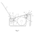
- the paper transport unit 6 with the driving rubber roller 3 and the blades 17 should be opened by rotation around the ejection roller 11, giving access to the paper reservoir 27 for easy paper roll change as shown in figure 3 .
- Such arrangement allows combining the easy loading with the transport function, providing to the printer an easy loading characteristics.
- the thermal printing device further comprises a journal paper exit 12 provided after the paper transport unit 6 and arranged close to the ballot discharge opening 5.
- the journal paper exit 12 is needed when a voting journal, a report or other information should be printed and ejected out of the device.
- a paper exit selector means 14 is provided after the paper exit end of the paper transport unit 6. As shown on figs 5 and 6 the paper exit selector means 14 is movable between two position in order to alternatively close and respectively open the ballot discharge opening 5 or the journal paper exit 12 so as when one of the two openings is open the other is fully closed. At the same time the paper exit selector means 14 serves for redirecting of the printed paper 20 to a ballot box via the ballot discharge opening 5 or outside the thermal printing device via the journal paper exit 12.
- the paper exit selector 14 is mounted pivotally and co-axially with the ejection roller 11.
- the transparent window 9 is arranged at a close distance to the upper part of the belts 13 of the paper transport unit 6 in order to present the ballot to the voter for voter's validation, and such a close distance is needed in order to keep the paper flat during the ballot presentation, to avoid parasitic reflection and to ensure a good ballot transport.
- the space between the transparent window 9 and the belts 13 is about 1 mm.
- At least one spring 24 and at least one corresponding spring loaded shaft 23 are mounted under the upper part of the belt 13 in order to create at least one contact point between the belt 13 and the transparent window 9.
- the spring loaded shaft 23 applies soft pressure on the belt 13 against the transparent window 19 limiting the potential friction and wearing between the belt and the window. Adjusting the spring force ensures a high flexibility in the paper transport traction force.
- the paper transport unit 6 is mechanically driven by the driving motor 4 of the thermal printing unit 28 through the driving rubber roller 3 in order to remove the motor 21.
- the intermediary gear 26 is arranged between and engages gear trains integral respectively with the pulley 7 and with the driving rubber roller 3. This arrangement allows a further cost reduction of the device.
- the thermal printing device operates as follows:
- the motor 21 starts moving the pulley 10 at a same or higher speed than the one of the printing unit.
- the paper 20 is taken onto the belt 13 at the pulley 7 and starts to progress under the window 9.
- a small space around one millimeter is left between the window 9 and the belts 13 in order to keep the paper close to the window 9 to have a clear readability and avoid parasitic reflection on the glass.
- the same or higher speed of the motor 21 helps the paper to remain flat and make it progress under the window 9.
- the motor 21 stops and the paper is cut by the blades 16 and 17.
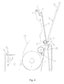
- ballot mode of the device at this stage, the printed ballot is presented to the voter for validation. After that the ballot 25 is caught between the pulley 10 and the ejection roller 11 and is ejected via the ballot discharge opening 5 to the ballot box as shown on figure 4 .
- the paper exit selector means 14 closes the journal paper exit 12 so as no paper can be inserted trough it in the device.
- journal mode of the device the paper exit selector means 14 moves to a second position closing the ballot discharge opening 5 and redirecting the printed paper out of the thermal printing device via the journal paper exit 12.
Landscapes
- Physics & Mathematics (AREA)
- General Physics & Mathematics (AREA)
- Electronic Switches (AREA)
- Handling Of Sheets (AREA)
- Accessory Devices And Overall Control Thereof (AREA)
- Sheets, Magazines, And Separation Thereof (AREA)
Abstract
Description
- The invention relates to a thermal printing device for electronic voting system.
- Electronic voting apparatus is used in different kind of elections. In the process of voting using such electronic voting apparatus the voter:
- first selects the candidate he/she intends to vote for;
- then the printer of the voting apparatus prints a coupon (ballot) corresponding to the voter's choice;
- printed coupon is presented to the voter usually under a transparent glass;
- after the voter's confirmation, the coupon is then cut and ejected into the ballot box.
- In the voting application, the printer does not have only to print the ballot but also transport it under a transparent window to get the voter's approval. Then the paper ballot is ejected into a ballot box. In some applications the printer of the voting apparatus has also to perform a journal printout at the end of the voting session.
- European patent application
EP1477939A1 discloses a printing system for electronic voting. The system comprises a frame with paper roll holder, a printing mechanism, a paper transport unit with belts, a housing with a transparent window and a ballot box. In such voting systems one of the main problems is paper loading that should be quick, easy and secured. - In the past years the paper loading in thermal printers has been moving from automatic paper loading to easy loading where the rubber roller of the printing head is a part of a cover giving access to the paper roll reservoir.
- The automatic paper loading consists in inserting the paper between the rubber roller and the thermal head of the printer. A sensor detecting these conditions triggers the printer motor start, making the rubber roller turns, then moving the paper trough the printer between the thermal printhead and the rubber roller.
- The easy paper loading consists in having the rubber roller integral with the cover giving access to the paper reservoir. When opening such cover, the rubber roller moves away from the thermal head, and gives a full access to the paper reservoir. The paper roll can be then easily substituted, and the cover can be closed again, pinching the paper between the rubber roller and the thermal printhead. The printer is then ready to print again.
- Thermal printers with easy paper loading are known for example from
FR2786727A1 FR2749289A1 - Printing devices for voting machines are known for being also able to print a journal when the election is closed. In this case the paper exit direction is changed from the ballot box to an external exit in order to present this printout.
- The target of the invention is to improve the paper loading in thermal printers for voting machine. In particular the invention object is to provide a compact and secure thermal printing device with simple construction and to minimize the number of parts in order to decrease the overall cost of such a printer.
- Another target of the invention is to provide thermal printing device for voting machine also able to perform a journal printout at the end of the voting session. Such operation has to be secured in order to prevent inserting a ballot trough the paper journal exit.
- These two targets of are achieved by the thermal printing device for electronic voting apparatus according to the present invention that comprises a casing with paper reservoir for receiving a paper roll, an openable external lid with a transparent window for observing of a printed part of the paper, a thermal printing unit, a paper transport unit for transporting the paper, arranged below the transparent window, and a ballot discharge opening of the casing provided after the paper transport unit, wherein the thermal printing unit comprises a thermo-printing head and a driving rubber roller for the paper that is integral part of the paper transport unit and the paper transport unit is openable in order to give access to the paper reservoir.
- According to a variant of the present invention the openable external lid is pivotally connected with the casing by a hinge arranged on one of the opposite ends of the openable external lid with respect to paper transport direction. Preferably the device further comprises a means for secure locking of the openable external lid.
- According to a further variant of the thermal printing device it further comprises a cutting device with two blades arranged after the thermal printing unit and before the paper transport unit, wherein one of the blades of the cutting device is integral part of the paper transport unit.
- Advantageously the paper transport unit is pivotally mounted on an ejection roller for the printed paper.
- Preferably the paper transport unit comprises at least one paper transport belt held between at least two pulleys, said belt being in contact with the ejection roller in order to eject the paper after its presentation to the voter.
- Advantageously the transparent window is arranged at a close distance to the belts of the paper transport unit to ensure flat presentation of the printed paper and avoid light reflection. Preferably at least one spring and at least one corresponding spring loaded shaft are mounted under the upper part of the belt in order to create at least one contact point between the belt and the transparent window.
- According to another embodiment of the thermal printing device it further comprises a journal paper exit provided after the paper transport unit and arranged close to the ballot discharge opening. Advantageously a paper exit selector means is provided after the paper transport unit for alternatively and simultaneously closing and respectively opening of the ballot discharge opening or the journal paper exit and for redirecting of the printed paper to a ballot box via the ballot discharge opening or outside the thermal printing device via the journal paper exit. Preferably the paper exit selector is mounted pivotally and co-axially with the ejection roller.
- The paper exit selector means according to this embodiment allows both easy redirecting of the printed paper and securing the work of the device.
- According to further embodiment of the thermal printing device the paper transport unit is actuated by a driving motor of the thermal printing unit through the driving rubber roller. Such arrangement allows reducing the costs for the motor for the paper transport unit
- The characteristics of the invention will be disclosed in details in the following description of preferred embodiments, given as a non-restrictive example, with reference to the attached drawings wherein:
-
Figure 1 is a schematic sectional view of a preferred embodiment of the thermal printing device for electronic voting apparatus according to the present invention; -
Figure 2 is a schematic sectional view of the variant offigure 1 with openable external lid opened. -
Figure 3 is a schematic sectional view of the variant offigure 1 with opened paper transport unit. -
Figure 4 is a detailed schematic sectional view of paper exit end of the paper transport unit with journal paper exit closed by the paper exit selector means and printer paper ballot directed to a ballot box. -
Figure 5 is the same view as infigure 4 with ballot discharge opening closed by the paper exit selector means and printed paper directed outside the thermal printing device via the journal paper exit. -
Figure 6 is a detailed schematic sectional view of a part of the paper transport unit arranged below the transparent window of the openable lid. -
Figures 7 and8 is a schematic sectional view of further variant of the thermal printing device for electronic voting apparatus according to the present invention with the openable lid pivotally connected with the casing by a hinge arranged close to the ejection roller for the printed paper. -
Figure 9 is a schematic sectional view of further variant of the thermal printing device for electronic voting apparatus according to the present invention with different actuation of the paper transport unit -
Figure 1 shows a preferred embodiment of the thermal printing device for electronic voting apparatus according to the present invention. The thermal printing device comprises acasing 1 withpaper reservoir 27 for receiving apaper roll 2, an openableexternal lid 19 with atransparent window 9 for observing of a printed part of the paper, athermal printing unit 28, apaper transport unit 6 for transporting the paper, arranged below thetransparent window 9, and aballot discharge opening 5 of the casing provided after thepaper transport unit 6. A cutting device comprising twoblades thermal printing unit 28 and before thepaper transport unit 6. - The
thermal printing unit 28 comprises a thermo-printing head 18, adriving rubber roller 3 for the paper and adriving motor 4. - The
paper transport unit 6 comprises at least onepaper transport belt 13 held between at least twopulleys belt 13 is in contact with anejection roller 11 in order to eject the printed and sawn coupon. Thepaper transport unit 6 is mechanically driven by amotor 21 trough anintermediary gear 26 engaged with a gear train integral with thepulley 10. Thepaper transport unit 6 is intended to transport the printed paper under thetransparent window 9 and then to the paper exit end. - One
electronic board 22 is driving the entire printing device and ensures the communication with the host. - In the present embodiment, the
driving rubber roller 3 and one of theblades 17 of the cutting device are integral with thepaper transport unit 6. Thepaper transport unit 6 is openable in order to give access to thepaper reservoir 27. In the present embodiment, thepaper transport unit 6 is pivotally mounted on theejection roller 11 for the printed paper. - In the present embodiment, the openable
external lid 19 is pivotally connected with thecasing 1 by ahinge 8 arranged on the end of the openableexternal lid 19 that is close to thethermal printing unit 28. In this arrangement the openableexternal lid 19 and thepaper transport unit 6 are openable in opposite directions. - In a variant of this embodiment the
hinge 8 is arranged on the side of the openableexternal lid 19 that is close to theejection roller 11 of thepaper transport unit 6. In this arrangement the openableexternal lid 19 and thepaper transport unit 6 are openable in one and the same direction. - In order to avoid unwished and unauthorized access to the inner part of the printing device the openable
external lid 19 is provided with ameans 15 for secure locking. The means 15 for secure locking could be for example a keylock arranged on that end of the openableexternal lid 19 opposite to the hingedend 8 as shown onfigure 1 . - To have access to the
paper reservoir 27 in a first step it is necessary to open theexternal cover 19 trough its rotation around thehinge 8 as shown onfigure 2 . - In a second step, the
paper transport unit 6 with the drivingrubber roller 3 and theblades 17 should be opened by rotation around theejection roller 11, giving access to thepaper reservoir 27 for easy paper roll change as shown infigure 3 . - When the
paper transport unit 6 opens the gear train that is integral with thepulley 10 separates from theintermediary gear 26. - Such arrangement allows combining the easy loading with the transport function, providing to the printer an easy loading characteristics.
- In a preferred embodiment the thermal printing device further comprises a
journal paper exit 12 provided after thepaper transport unit 6 and arranged close to theballot discharge opening 5. Thejournal paper exit 12 is needed when a voting journal, a report or other information should be printed and ejected out of the device. In order to secure this function of the device a paper exit selector means 14 is provided after the paper exit end of thepaper transport unit 6. As shown onfigs 5 and 6 the paper exit selector means 14 is movable between two position in order to alternatively close and respectively open theballot discharge opening 5 or thejournal paper exit 12 so as when one of the two openings is open the other is fully closed. At the same time the paper exit selector means 14 serves for redirecting of the printedpaper 20 to a ballot box via theballot discharge opening 5 or outside the thermal printing device via thejournal paper exit 12. - Preferably the
paper exit selector 14 is mounted pivotally and co-axially with theejection roller 11. - In another preferred embodiment the
transparent window 9 is arranged at a close distance to the upper part of thebelts 13 of thepaper transport unit 6 in order to present the ballot to the voter for voter's validation, and such a close distance is needed in order to keep the paper flat during the ballot presentation, to avoid parasitic reflection and to ensure a good ballot transport. The space between thetransparent window 9 and thebelts 13 is about 1 mm. - In order to improve the traction force of the
paper transport unit 6 and as shown onfigure 6 , at least onespring 24 and at least one corresponding spring loadedshaft 23 are mounted under the upper part of thebelt 13 in order to create at least one contact point between thebelt 13 and thetransparent window 9. The spring loadedshaft 23 applies soft pressure on thebelt 13 against thetransparent window 19 limiting the potential friction and wearing between the belt and the window. Adjusting the spring force ensures a high flexibility in the paper transport traction force. - In a further embodiment of the invention presented on
figure 9 , thepaper transport unit 6 is mechanically driven by the drivingmotor 4 of thethermal printing unit 28 through the drivingrubber roller 3 in order to remove themotor 21. In this non limiting example, theintermediary gear 26 is arranged between and engages gear trains integral respectively with thepulley 7 and with the drivingrubber roller 3. This arrangement allows a further cost reduction of the device. - The thermal printing device according to the present invention operates as follows:
- In order to load the
paper roll 2 in thepaper reservoir 27 of the device both the openableexternal lid 19 and thepaper transport unit 6 should be successively opened. When thepaper roll 2 is loaded then thepaper transport unit 6 should be closed so as the end part of thepaper 20 is pressed between the thermo-printing head 18 and the drivingrubber roller 3. Then the openableexternal lid 19 should be closed and secured by thekeylock 15. - When the
thermal printing unit 28 starts printing simultaneously themotor 21 starts moving thepulley 10 at a same or higher speed than the one of the printing unit. Thepaper 20 is taken onto thebelt 13 at thepulley 7 and starts to progress under thewindow 9. A small space around one millimeter is left between thewindow 9 and thebelts 13 in order to keep the paper close to thewindow 9 to have a clear readability and avoid parasitic reflection on the glass. - The same or higher speed of the
motor 21 helps the paper to remain flat and make it progress under thewindow 9. When the printout is done themotor 21 stops and the paper is cut by theblades - In ballot mode of the device, at this stage, the printed ballot is presented to the voter for validation. After that the
ballot 25 is caught between thepulley 10 and theejection roller 11 and is ejected via theballot discharge opening 5 to the ballot box as shown onfigure 4 . In this mode the paper exit selector means 14 closes thejournal paper exit 12 so as no paper can be inserted trough it in the device. - In journal mode of the device the paper exit selector means 14 moves to a second position closing the
ballot discharge opening 5 and redirecting the printed paper out of the thermal printing device via thejournal paper exit 12. - Various modifications and/or additions of parts will be apparent to those skilled in the art that will remain within the field and scope of the present invention defined in appended claims. All the parts may further be replaced with other technically equivalent elements.
- Reference signs for technical features are included in the claims for the sole purpose of increasing the intelligibility of the claims and accordingly, such reference signs do not have any limiting effect on the interpretation of each element identified by way of example by such reference signs.
Claims (13)
- Thermal printing device for electronic voting apparatus comprising a casing (1) with paper reservoir (27) for receiving a paper roll (2), an openable external lid (19) with a transparent window (9) for observing of a printed part of the paper, a thermal printing unit (28), a paper transport unit (6) for transporting the paper, arranged below the transparent window (9), and a ballot discharge opening (5) of the casing provided after the paper transport unit (6), wherein the thermal printing unit (28) comprises a thermo-printing head (18) and a driving rubber roller (3) for the paper,
characterized in that
the driving rubber roller (3) is integral part of the paper transport unit (6) and the paper transport unit (6) is openable in order to give access to the paper reservoir (27). - Thermal printing device according to claim 1, characterized in that the openable external lid (19) is pivotally connected with the casing (1) by a hinge (8) arranged on one of the opposite ends of the openable external lid (19) with respect to paper transport direction.
- Thermal printing device according to claim 1 or 2, characterized in that it further comprises a means (15) for secure locking of the openable external lid (19).
- Thermal printing device according to any of the preceding claims, characterized in that it further comprises a cutting device with two blades (16 and 17) arranged after the thermal printing unit (28) and before the paper transport unit (6).
- Thermal printing device according to claim 4, characterized in that one of the blades (17) of the cutting device is integral part of the paper transport unit (6).
- Thermal printing device according to any of the preceding claims, characterized in that the paper transport unit (6) is pivotally mounted on an ejection roller (11) for the printed paper.
- Thermal printing device according to any of the preceding claims, characterized in that the paper transport unit (6) comprises at least one paper transport belt (13) held between at least two pulleys (7 and 10), said at least one belt (13) being in contact with the ejection roller (11) in order to eject the paper after its presentation to the voter.
- Thermal printing device according to any of the preceding claims, characterized in that the transparent window (9) is arranged at a close distance to the belt (13) of the paper transport unit (6) to ensure flat presentation of the printed paper and avoid light reflection.
- Thermal printing device according to claim 8, characterized in that at least one spring (24) and at least one corresponding spring loaded shaft (23) are mounted under the upper part of the belt (13) in order to create at least one contact point between the belt (13) and the transparent window (9).
- Thermal printing device according to any of the preceding claims, characterized in that it further comprises a journal paper exit (12) provided after the paper transport unit (6) and arranged close to the ballot discharge opening (5).
- Thermal printing device according to claim 10, characterized in that it further comprises a paper exit selector means (14) movable between two positions for alternatively and simultaneously closing and respectively opening of the ballot discharge opening (5) or the journal paper exit (12) and for redirecting of the printed paper (20) to a ballot box via the ballot discharge opening (5) or outside the thermal printing device via the journal paper exit (12).
- Thermal printing device according to claim 11, characterized in that the paper exit selector (14) is mounted pivotally and co-axially with the ejection roller (11).
- Thermal printing device according to any of the previous claim, characterized in that the paper transport unit (6) is actuated by a driving motor (4) of the thermal printing unit (28) through the driving rubber roller (3).
Priority Applications (5)
| Application Number | Priority Date | Filing Date | Title |
|---|---|---|---|
| ES13157369.3T ES2594606T3 (en) | 2013-03-01 | 2013-03-01 | Thermal printing device for electronic voting device |
| EP13157369.3A EP2772364B1 (en) | 2013-03-01 | 2013-03-01 | Thermal printing device for electronic voting apparatus |
| US14/770,310 US9235944B1 (en) | 2013-03-01 | 2014-02-21 | Thermal printing device for electronic voting apparatus |
| PCT/EP2014/053431 WO2014131703A1 (en) | 2013-03-01 | 2014-02-21 | Thermal printing device for electronic voting apparatus |
| CN201480011412.3A CN105026166B (en) | 2013-03-01 | 2014-02-21 | Thermal printing unit for electronic voting equipment |
Applications Claiming Priority (1)
| Application Number | Priority Date | Filing Date | Title |
|---|---|---|---|
| EP13157369.3A EP2772364B1 (en) | 2013-03-01 | 2013-03-01 | Thermal printing device for electronic voting apparatus |
Publications (2)
| Publication Number | Publication Date |
|---|---|
| EP2772364A1 true EP2772364A1 (en) | 2014-09-03 |
| EP2772364B1 EP2772364B1 (en) | 2016-07-06 |
Family
ID=47779941
Family Applications (1)
| Application Number | Title | Priority Date | Filing Date |
|---|---|---|---|
| EP13157369.3A Active EP2772364B1 (en) | 2013-03-01 | 2013-03-01 | Thermal printing device for electronic voting apparatus |
Country Status (5)
| Country | Link |
|---|---|
| US (1) | US9235944B1 (en) |
| EP (1) | EP2772364B1 (en) |
| CN (1) | CN105026166B (en) |
| ES (1) | ES2594606T3 (en) |
| WO (1) | WO2014131703A1 (en) |
Families Citing this family (4)
| Publication number | Priority date | Publication date | Assignee | Title |
|---|---|---|---|---|
| US10467484B2 (en) * | 2017-06-01 | 2019-11-05 | Aptiv Technologies Limited | Driver fatigue warning system |
| WO2019111042A1 (en) * | 2017-12-07 | 2019-06-13 | Yossimi Marcus | Device for printing out votes in electronic voting systems |
| CN111311813B (en) * | 2020-04-24 | 2024-07-12 | 辽宁科技大学 | Modularized automatic ticket machine |
| CN115909585B (en) * | 2023-03-03 | 2023-05-12 | 广东清华文通科技有限公司 | Three-state control circuit capable of ensuring complete locking during fast voting and re-tensioning |
Citations (4)
| Publication number | Priority date | Publication date | Assignee | Title |
|---|---|---|---|---|
| JPS6398451A (en) * | 1986-10-15 | 1988-04-28 | Sekonitsuku:Kk | Recorder |
| FR2749289A1 (en) | 1996-06-03 | 1997-12-05 | Axiohm | DEVICE FOR ISSUING TICKETS FORMED BY TAPE TRUNKS |
| FR2786727A1 (en) | 1998-12-02 | 2000-06-09 | A P S Engineering | QUICK CLOSING THERMAL PRINTING DEVICE |
| EP1477939A1 (en) | 2003-05-14 | 2004-11-17 | Wincor Nixdorf International GmbH | Printing system for electronic voting |
Family Cites Families (10)
| Publication number | Priority date | Publication date | Assignee | Title |
|---|---|---|---|---|
| JPS61190431A (en) * | 1985-02-13 | 1986-08-25 | 株式会社 サト− | Table type thermal printer |
| JP2557714B2 (en) * | 1989-12-14 | 1996-11-27 | 株式会社新盛インダストリーズ | Label printer device |
| US6113292A (en) * | 1994-12-02 | 2000-09-05 | Seiko Epson Corporation | Printer head release mechanism |
| JP2002279126A (en) * | 2001-03-16 | 2002-09-27 | Victor Co Of Japan Ltd | Electronic voting device |
| JP2004114640A (en) * | 2002-09-30 | 2004-04-15 | Fujitsu Ltd | Thermal printer and portable terminal device |
| KR100637871B1 (en) * | 2005-06-21 | 2006-10-24 | (주)나노스토리지 | Electronic voting system and electronic voting method |
| GB0617379D0 (en) * | 2006-09-04 | 2006-10-11 | Het Nl Kanker I | Digital polling system and method |
| KR20090118223A (en) * | 2008-05-13 | 2009-11-18 | 미루데이타시스템 주식회사 | Electronic voting device |
| JP2011168029A (en) * | 2010-02-22 | 2011-09-01 | Seiko Instruments Inc | Printer |
| CN201936330U (en) * | 2011-01-19 | 2011-08-17 | 河北科技大学 | Portable vote reader |
-
2013
- 2013-03-01 ES ES13157369.3T patent/ES2594606T3/en active Active
- 2013-03-01 EP EP13157369.3A patent/EP2772364B1/en active Active
-
2014
- 2014-02-21 WO PCT/EP2014/053431 patent/WO2014131703A1/en not_active Ceased
- 2014-02-21 CN CN201480011412.3A patent/CN105026166B/en active Active
- 2014-02-21 US US14/770,310 patent/US9235944B1/en active Active
Patent Citations (4)
| Publication number | Priority date | Publication date | Assignee | Title |
|---|---|---|---|---|
| JPS6398451A (en) * | 1986-10-15 | 1988-04-28 | Sekonitsuku:Kk | Recorder |
| FR2749289A1 (en) | 1996-06-03 | 1997-12-05 | Axiohm | DEVICE FOR ISSUING TICKETS FORMED BY TAPE TRUNKS |
| FR2786727A1 (en) | 1998-12-02 | 2000-06-09 | A P S Engineering | QUICK CLOSING THERMAL PRINTING DEVICE |
| EP1477939A1 (en) | 2003-05-14 | 2004-11-17 | Wincor Nixdorf International GmbH | Printing system for electronic voting |
Also Published As
| Publication number | Publication date |
|---|---|
| ES2594606T3 (en) | 2016-12-21 |
| CN105026166B (en) | 2017-03-15 |
| WO2014131703A1 (en) | 2014-09-04 |
| CN105026166A (en) | 2015-11-04 |
| US9235944B1 (en) | 2016-01-12 |
| US20160005251A1 (en) | 2016-01-07 |
| EP2772364B1 (en) | 2016-07-06 |
Similar Documents
| Publication | Publication Date | Title |
|---|---|---|
| EP2772364B1 (en) | Thermal printing device for electronic voting apparatus | |
| JP5941657B2 (en) | Printer with cutter | |
| EP2279834A2 (en) | Cutter mechanism and printer with such a cutter | |
| CN102673183B (en) | Compound printing equipment | |
| US11325402B2 (en) | Printer apparatus with flapper attached to conveying route cover | |
| EP2727736A1 (en) | Printer including presenter part and cutter part that move together | |
| US6827515B2 (en) | Stacker for a printer | |
| EP2362364A1 (en) | Paper discharge device | |
| JP6788446B2 (en) | Paper leaf storage device and paper leaf storage method | |
| JP2017052180A (en) | Printer device | |
| JP2008276484A (en) | Card issuing device | |
| CN102289897A (en) | Self-service printing terminal with sealing function | |
| JP6263097B2 (en) | Printing device | |
| EP2927006B1 (en) | Printer | |
| KR100637871B1 (en) | Electronic voting system and electronic voting method | |
| CN109572245B (en) | Printer device | |
| JP4575032B2 (en) | Medium processing apparatus and medium issuing apparatus using the same | |
| EP3162580B1 (en) | Printer device | |
| JPH0887610A (en) | Recording medium processing device and recording medium printing method | |
| KR100739940B1 (en) | Receipt Machine and Control Method | |
| JPH0215167Y2 (en) | ||
| JP5420979B2 (en) | Roll paper loading mechanism | |
| JP5806580B2 (en) | Printer device and printer device control method | |
| JP4531300B2 (en) | In-car supplement ticket issuing device | |
| US20200282583A1 (en) | Cutter mechanism for a printer and methods of cutting paper media in a printer |
Legal Events
| Date | Code | Title | Description |
|---|---|---|---|
| PUAI | Public reference made under article 153(3) epc to a published international application that has entered the european phase |
Free format text: ORIGINAL CODE: 0009012 |
|
| 17P | Request for examination filed |
Effective date: 20130301 |
|
| AK | Designated contracting states |
Kind code of ref document: A1 Designated state(s): AL AT BE BG CH CY CZ DE DK EE ES FI FR GB GR HR HU IE IS IT LI LT LU LV MC MK MT NL NO PL PT RO RS SE SI SK SM TR |
|
| AX | Request for extension of the european patent |
Extension state: BA ME |
|
| R17P | Request for examination filed (corrected) |
Effective date: 20150128 |
|
| RBV | Designated contracting states (corrected) |
Designated state(s): AL AT BE BG CH CY CZ DE DK EE ES FI FR GB GR HR HU IE IS IT LI LT LU LV MC MK MT NL NO PL PT RO RS SE SI SK SM TR |
|
| RIC1 | Information provided on ipc code assigned before grant |
Ipc: B41J 15/04 20060101ALI20150929BHEP Ipc: B41J 11/70 20060101AFI20150929BHEP |
|
| GRAP | Despatch of communication of intention to grant a patent |
Free format text: ORIGINAL CODE: EPIDOSNIGR1 |
|
| INTG | Intention to grant announced |
Effective date: 20151120 |
|
| GRAS | Grant fee paid |
Free format text: ORIGINAL CODE: EPIDOSNIGR3 |
|
| GRAP | Despatch of communication of intention to grant a patent |
Free format text: ORIGINAL CODE: EPIDOSNIGR1 |
|
| GRAS | Grant fee paid |
Free format text: ORIGINAL CODE: EPIDOSNIGR3 |
|
| GRAA | (expected) grant |
Free format text: ORIGINAL CODE: 0009210 |
|
| INTG | Intention to grant announced |
Effective date: 20160523 |
|
| AK | Designated contracting states |
Kind code of ref document: B1 Designated state(s): AL AT BE BG CH CY CZ DE DK EE ES FI FR GB GR HR HU IE IS IT LI LT LU LV MC MK MT NL NO PL PT RO RS SE SI SK SM TR |
|
| REG | Reference to a national code |
Ref country code: GB Ref legal event code: FG4D |
|
| REG | Reference to a national code |
Ref country code: AT Ref legal event code: REF Ref document number: 810410 Country of ref document: AT Kind code of ref document: T Effective date: 20160715 Ref country code: CH Ref legal event code: EP |
|
| REG | Reference to a national code |
Ref country code: IE Ref legal event code: FG4D |
|
| REG | Reference to a national code |
Ref country code: DE Ref legal event code: R096 Ref document number: 602013009050 Country of ref document: DE |
|
| REG | Reference to a national code |
Ref country code: NL Ref legal event code: MP Effective date: 20160706 |
|
| REG | Reference to a national code |
Ref country code: LT Ref legal event code: MG4D |
|
| REG | Reference to a national code |
Ref country code: AT Ref legal event code: MK05 Ref document number: 810410 Country of ref document: AT Kind code of ref document: T Effective date: 20160706 |
|
| REG | Reference to a national code |
Ref country code: ES Ref legal event code: FG2A Ref document number: 2594606 Country of ref document: ES Kind code of ref document: T3 Effective date: 20161221 |
|
| PG25 | Lapsed in a contracting state [announced via postgrant information from national office to epo] |
Ref country code: FI Free format text: LAPSE BECAUSE OF FAILURE TO SUBMIT A TRANSLATION OF THE DESCRIPTION OR TO PAY THE FEE WITHIN THE PRESCRIBED TIME-LIMIT Effective date: 20160706 Ref country code: LT Free format text: LAPSE BECAUSE OF FAILURE TO SUBMIT A TRANSLATION OF THE DESCRIPTION OR TO PAY THE FEE WITHIN THE PRESCRIBED TIME-LIMIT Effective date: 20160706 Ref country code: HR Free format text: LAPSE BECAUSE OF FAILURE TO SUBMIT A TRANSLATION OF THE DESCRIPTION OR TO PAY THE FEE WITHIN THE PRESCRIBED TIME-LIMIT Effective date: 20160706 Ref country code: NL Free format text: LAPSE BECAUSE OF FAILURE TO SUBMIT A TRANSLATION OF THE DESCRIPTION OR TO PAY THE FEE WITHIN THE PRESCRIBED TIME-LIMIT Effective date: 20160706 Ref country code: IS Free format text: LAPSE BECAUSE OF FAILURE TO SUBMIT A TRANSLATION OF THE DESCRIPTION OR TO PAY THE FEE WITHIN THE PRESCRIBED TIME-LIMIT Effective date: 20161106 Ref country code: NO Free format text: LAPSE BECAUSE OF FAILURE TO SUBMIT A TRANSLATION OF THE DESCRIPTION OR TO PAY THE FEE WITHIN THE PRESCRIBED TIME-LIMIT Effective date: 20161006 Ref country code: RS Free format text: LAPSE BECAUSE OF FAILURE TO SUBMIT A TRANSLATION OF THE DESCRIPTION OR TO PAY THE FEE WITHIN THE PRESCRIBED TIME-LIMIT Effective date: 20160706 |
|
| REG | Reference to a national code |
Ref country code: FR Ref legal event code: PLFP Year of fee payment: 5 |
|
| PG25 | Lapsed in a contracting state [announced via postgrant information from national office to epo] |
Ref country code: BE Free format text: LAPSE BECAUSE OF FAILURE TO SUBMIT A TRANSLATION OF THE DESCRIPTION OR TO PAY THE FEE WITHIN THE PRESCRIBED TIME-LIMIT Effective date: 20160706 Ref country code: LV Free format text: LAPSE BECAUSE OF FAILURE TO SUBMIT A TRANSLATION OF THE DESCRIPTION OR TO PAY THE FEE WITHIN THE PRESCRIBED TIME-LIMIT Effective date: 20160706 Ref country code: AT Free format text: LAPSE BECAUSE OF FAILURE TO SUBMIT A TRANSLATION OF THE DESCRIPTION OR TO PAY THE FEE WITHIN THE PRESCRIBED TIME-LIMIT Effective date: 20160706 Ref country code: PL Free format text: LAPSE BECAUSE OF FAILURE TO SUBMIT A TRANSLATION OF THE DESCRIPTION OR TO PAY THE FEE WITHIN THE PRESCRIBED TIME-LIMIT Effective date: 20160706 Ref country code: PT Free format text: LAPSE BECAUSE OF FAILURE TO SUBMIT A TRANSLATION OF THE DESCRIPTION OR TO PAY THE FEE WITHIN THE PRESCRIBED TIME-LIMIT Effective date: 20161107 Ref country code: SE Free format text: LAPSE BECAUSE OF FAILURE TO SUBMIT A TRANSLATION OF THE DESCRIPTION OR TO PAY THE FEE WITHIN THE PRESCRIBED TIME-LIMIT Effective date: 20160706 Ref country code: GR Free format text: LAPSE BECAUSE OF FAILURE TO SUBMIT A TRANSLATION OF THE DESCRIPTION OR TO PAY THE FEE WITHIN THE PRESCRIBED TIME-LIMIT Effective date: 20161007 |
|
| REG | Reference to a national code |
Ref country code: DE Ref legal event code: R097 Ref document number: 602013009050 Country of ref document: DE |
|
| PG25 | Lapsed in a contracting state [announced via postgrant information from national office to epo] |
Ref country code: EE Free format text: LAPSE BECAUSE OF FAILURE TO SUBMIT A TRANSLATION OF THE DESCRIPTION OR TO PAY THE FEE WITHIN THE PRESCRIBED TIME-LIMIT Effective date: 20160706 Ref country code: RO Free format text: LAPSE BECAUSE OF FAILURE TO SUBMIT A TRANSLATION OF THE DESCRIPTION OR TO PAY THE FEE WITHIN THE PRESCRIBED TIME-LIMIT Effective date: 20160706 |
|
| PLBE | No opposition filed within time limit |
Free format text: ORIGINAL CODE: 0009261 |
|
| STAA | Information on the status of an ep patent application or granted ep patent |
Free format text: STATUS: NO OPPOSITION FILED WITHIN TIME LIMIT |
|
| PG25 | Lapsed in a contracting state [announced via postgrant information from national office to epo] |
Ref country code: SK Free format text: LAPSE BECAUSE OF FAILURE TO SUBMIT A TRANSLATION OF THE DESCRIPTION OR TO PAY THE FEE WITHIN THE PRESCRIBED TIME-LIMIT Effective date: 20160706 Ref country code: DK Free format text: LAPSE BECAUSE OF FAILURE TO SUBMIT A TRANSLATION OF THE DESCRIPTION OR TO PAY THE FEE WITHIN THE PRESCRIBED TIME-LIMIT Effective date: 20160706 Ref country code: SM Free format text: LAPSE BECAUSE OF FAILURE TO SUBMIT A TRANSLATION OF THE DESCRIPTION OR TO PAY THE FEE WITHIN THE PRESCRIBED TIME-LIMIT Effective date: 20160706 Ref country code: BG Free format text: LAPSE BECAUSE OF FAILURE TO SUBMIT A TRANSLATION OF THE DESCRIPTION OR TO PAY THE FEE WITHIN THE PRESCRIBED TIME-LIMIT Effective date: 20161006 Ref country code: CZ Free format text: LAPSE BECAUSE OF FAILURE TO SUBMIT A TRANSLATION OF THE DESCRIPTION OR TO PAY THE FEE WITHIN THE PRESCRIBED TIME-LIMIT Effective date: 20160706 |
|
| 26N | No opposition filed |
Effective date: 20170407 |
|
| PG25 | Lapsed in a contracting state [announced via postgrant information from national office to epo] |
Ref country code: SI Free format text: LAPSE BECAUSE OF FAILURE TO SUBMIT A TRANSLATION OF THE DESCRIPTION OR TO PAY THE FEE WITHIN THE PRESCRIBED TIME-LIMIT Effective date: 20160706 |
|
| REG | Reference to a national code |
Ref country code: CH Ref legal event code: PL |
|
| PG25 | Lapsed in a contracting state [announced via postgrant information from national office to epo] |
Ref country code: MC Free format text: LAPSE BECAUSE OF FAILURE TO SUBMIT A TRANSLATION OF THE DESCRIPTION OR TO PAY THE FEE WITHIN THE PRESCRIBED TIME-LIMIT Effective date: 20160706 |
|
| REG | Reference to a national code |
Ref country code: IE Ref legal event code: MM4A |
|
| REG | Reference to a national code |
Ref country code: FR Ref legal event code: PLFP Year of fee payment: 6 |
|
| PG25 | Lapsed in a contracting state [announced via postgrant information from national office to epo] |
Ref country code: LU Free format text: LAPSE BECAUSE OF NON-PAYMENT OF DUE FEES Effective date: 20170301 |
|
| PG25 | Lapsed in a contracting state [announced via postgrant information from national office to epo] |
Ref country code: IE Free format text: LAPSE BECAUSE OF NON-PAYMENT OF DUE FEES Effective date: 20170301 Ref country code: LI Free format text: LAPSE BECAUSE OF NON-PAYMENT OF DUE FEES Effective date: 20170331 Ref country code: CH Free format text: LAPSE BECAUSE OF NON-PAYMENT OF DUE FEES Effective date: 20170331 |
|
| PG25 | Lapsed in a contracting state [announced via postgrant information from national office to epo] |
Ref country code: MT Free format text: LAPSE BECAUSE OF NON-PAYMENT OF DUE FEES Effective date: 20170301 |
|
| PG25 | Lapsed in a contracting state [announced via postgrant information from national office to epo] |
Ref country code: AL Free format text: LAPSE BECAUSE OF FAILURE TO SUBMIT A TRANSLATION OF THE DESCRIPTION OR TO PAY THE FEE WITHIN THE PRESCRIBED TIME-LIMIT Effective date: 20160706 |
|
| PG25 | Lapsed in a contracting state [announced via postgrant information from national office to epo] |
Ref country code: HU Free format text: LAPSE BECAUSE OF FAILURE TO SUBMIT A TRANSLATION OF THE DESCRIPTION OR TO PAY THE FEE WITHIN THE PRESCRIBED TIME-LIMIT; INVALID AB INITIO Effective date: 20130301 |
|
| PG25 | Lapsed in a contracting state [announced via postgrant information from national office to epo] |
Ref country code: CY Free format text: LAPSE BECAUSE OF NON-PAYMENT OF DUE FEES Effective date: 20160706 |
|
| PG25 | Lapsed in a contracting state [announced via postgrant information from national office to epo] |
Ref country code: MK Free format text: LAPSE BECAUSE OF FAILURE TO SUBMIT A TRANSLATION OF THE DESCRIPTION OR TO PAY THE FEE WITHIN THE PRESCRIBED TIME-LIMIT Effective date: 20160706 |
|
| PGFP | Annual fee paid to national office [announced via postgrant information from national office to epo] |
Ref country code: TR Payment date: 20220301 Year of fee payment: 10 |
|
| PGFP | Annual fee paid to national office [announced via postgrant information from national office to epo] |
Ref country code: ES Payment date: 20220427 Year of fee payment: 10 |
|
| REG | Reference to a national code |
Ref country code: ES Ref legal event code: FD2A Effective date: 20240429 |
|
| PG25 | Lapsed in a contracting state [announced via postgrant information from national office to epo] |
Ref country code: ES Free format text: LAPSE BECAUSE OF NON-PAYMENT OF DUE FEES Effective date: 20230302 |
|
| PG25 | Lapsed in a contracting state [announced via postgrant information from national office to epo] |
Ref country code: ES Free format text: LAPSE BECAUSE OF NON-PAYMENT OF DUE FEES Effective date: 20230302 |
|
| PGFP | Annual fee paid to national office [announced via postgrant information from national office to epo] |
Ref country code: GB Payment date: 20260310 Year of fee payment: 14 |
|
| PGFP | Annual fee paid to national office [announced via postgrant information from national office to epo] |
Ref country code: DE Payment date: 20260318 Year of fee payment: 14 |
|
| PGFP | Annual fee paid to national office [announced via postgrant information from national office to epo] |
Ref country code: IT Payment date: 20260311 Year of fee payment: 14 |
|
| PGFP | Annual fee paid to national office [announced via postgrant information from national office to epo] |
Ref country code: FR Payment date: 20260319 Year of fee payment: 14 |