EP2772334A2 - Weld portion repairing method and weld portion repairing apparatus - Google Patents
Weld portion repairing method and weld portion repairing apparatus Download PDFInfo
- Publication number
- EP2772334A2 EP2772334A2 EP14156864.2A EP14156864A EP2772334A2 EP 2772334 A2 EP2772334 A2 EP 2772334A2 EP 14156864 A EP14156864 A EP 14156864A EP 2772334 A2 EP2772334 A2 EP 2772334A2
- Authority
- EP
- European Patent Office
- Prior art keywords
- weld portion
- flaw detection
- weld
- repairing
- boundary position
- Prior art date
- Legal status (The legal status is an assumption and is not a legal conclusion. Google has not performed a legal analysis and makes no representation as to the accuracy of the status listed.)
- Withdrawn
Links
- 238000000034 method Methods 0.000 title claims abstract description 39
- 238000001514 detection method Methods 0.000 claims abstract description 184
- 230000008439 repair process Effects 0.000 claims abstract description 72
- 238000007689 inspection Methods 0.000 claims description 94
- 238000003384 imaging method Methods 0.000 claims description 61
- 238000011179 visual inspection Methods 0.000 claims description 40
- 239000000463 material Substances 0.000 claims description 36
- XLYOFNOQVPJJNP-UHFFFAOYSA-N water Substances O XLYOFNOQVPJJNP-UHFFFAOYSA-N 0.000 description 66
- 238000002347 injection Methods 0.000 description 58
- 239000007924 injection Substances 0.000 description 58
- 239000000498 cooling water Substances 0.000 description 51
- 238000012360 testing method Methods 0.000 description 50
- 238000003780 insertion Methods 0.000 description 25
- 230000037431 insertion Effects 0.000 description 25
- 238000010586 diagram Methods 0.000 description 16
- 239000000523 sample Substances 0.000 description 10
- 238000006073 displacement reaction Methods 0.000 description 9
- 238000009434 installation Methods 0.000 description 9
- 238000005520 cutting process Methods 0.000 description 6
- 229910001220 stainless steel Inorganic materials 0.000 description 6
- 239000010935 stainless steel Substances 0.000 description 6
- 238000012790 confirmation Methods 0.000 description 4
- 229910000851 Alloy steel Inorganic materials 0.000 description 3
- 239000011324 bead Substances 0.000 description 3
- 230000035515 penetration Effects 0.000 description 3
- 230000000007 visual effect Effects 0.000 description 3
- PXHVJJICTQNCMI-UHFFFAOYSA-N Nickel Chemical compound [Ni] PXHVJJICTQNCMI-UHFFFAOYSA-N 0.000 description 2
- 230000007797 corrosion Effects 0.000 description 2
- 238000005260 corrosion Methods 0.000 description 2
- 230000007547 defect Effects 0.000 description 2
- 238000013461 design Methods 0.000 description 2
- 230000000694 effects Effects 0.000 description 2
- 239000000446 fuel Substances 0.000 description 2
- 238000005259 measurement Methods 0.000 description 2
- 239000002184 metal Substances 0.000 description 2
- 229910052751 metal Inorganic materials 0.000 description 2
- 239000011555 saturated liquid Substances 0.000 description 2
- 238000012546 transfer Methods 0.000 description 2
- QGZKDVFQNNGYKY-UHFFFAOYSA-N Ammonia Chemical compound N QGZKDVFQNNGYKY-UHFFFAOYSA-N 0.000 description 1
- 229910045601 alloy Inorganic materials 0.000 description 1
- 239000000956 alloy Substances 0.000 description 1
- QVGXLLKOCUKJST-UHFFFAOYSA-N atomic oxygen Chemical compound [O] QVGXLLKOCUKJST-UHFFFAOYSA-N 0.000 description 1
- 229910000963 austenitic stainless steel Inorganic materials 0.000 description 1
- 230000005540 biological transmission Effects 0.000 description 1
- 229910052799 carbon Inorganic materials 0.000 description 1
- 239000002826 coolant Substances 0.000 description 1
- 230000006866 deterioration Effects 0.000 description 1
- 238000009826 distribution Methods 0.000 description 1
- 239000000284 extract Substances 0.000 description 1
- 239000007789 gas Substances 0.000 description 1
- 239000012535 impurity Substances 0.000 description 1
- 229910001026 inconel Inorganic materials 0.000 description 1
- 238000012423 maintenance Methods 0.000 description 1
- 229910052759 nickel Inorganic materials 0.000 description 1
- 229910052760 oxygen Inorganic materials 0.000 description 1
- 239000001301 oxygen Substances 0.000 description 1
- 238000005192 partition Methods 0.000 description 1
- 230000035699 permeability Effects 0.000 description 1
- 230000002265 prevention Effects 0.000 description 1
- 238000005096 rolling process Methods 0.000 description 1
- 239000013535 sea water Substances 0.000 description 1
- 238000005480 shot peening Methods 0.000 description 1
- 239000000243 solution Substances 0.000 description 1
- 125000006850 spacer group Chemical group 0.000 description 1
Images






Classifications
-
- G—PHYSICS
- G21—NUCLEAR PHYSICS; NUCLEAR ENGINEERING
- G21C—NUCLEAR REACTORS
- G21C19/00—Arrangements for treating, for handling, or for facilitating the handling of, fuel or other materials which are used within the reactor, e.g. within its pressure vessel
- G21C19/20—Arrangements for introducing objects into the pressure vessel; Arrangements for handling objects within the pressure vessel; Arrangements for removing objects from the pressure vessel
- G21C19/207—Assembling, maintenance or repair of reactor components
-
- B—PERFORMING OPERATIONS; TRANSPORTING
- B23—MACHINE TOOLS; METAL-WORKING NOT OTHERWISE PROVIDED FOR
- B23P—METAL-WORKING NOT OTHERWISE PROVIDED FOR; COMBINED OPERATIONS; UNIVERSAL MACHINE TOOLS
- B23P6/00—Restoring or reconditioning objects
- B23P6/04—Repairing fractures or cracked metal parts or products, e.g. castings
-
- G—PHYSICS
- G01—MEASURING; TESTING
- G01N—INVESTIGATING OR ANALYSING MATERIALS BY DETERMINING THEIR CHEMICAL OR PHYSICAL PROPERTIES
- G01N27/00—Investigating or analysing materials by the use of electric, electrochemical, or magnetic means
- G01N27/72—Investigating or analysing materials by the use of electric, electrochemical, or magnetic means by investigating magnetic variables
- G01N27/82—Investigating or analysing materials by the use of electric, electrochemical, or magnetic means by investigating magnetic variables for investigating the presence of flaws
- G01N27/90—Investigating or analysing materials by the use of electric, electrochemical, or magnetic means by investigating magnetic variables for investigating the presence of flaws using eddy currents
- G01N27/9013—Arrangements for scanning
- G01N27/902—Arrangements for scanning by moving the sensors
-
- G—PHYSICS
- G21—NUCLEAR PHYSICS; NUCLEAR ENGINEERING
- G21C—NUCLEAR REACTORS
- G21C17/00—Monitoring; Testing ; Maintaining
- G21C17/017—Inspection or maintenance of pipe-lines or tubes in nuclear installations
-
- C—CHEMISTRY; METALLURGY
- C21—METALLURGY OF IRON
- C21D—MODIFYING THE PHYSICAL STRUCTURE OF FERROUS METALS; GENERAL DEVICES FOR HEAT TREATMENT OF FERROUS OR NON-FERROUS METALS OR ALLOYS; MAKING METAL MALLEABLE, e.g. BY DECARBURISATION OR TEMPERING
- C21D7/00—Modifying the physical properties of iron or steel by deformation
- C21D7/02—Modifying the physical properties of iron or steel by deformation by cold working
- C21D7/04—Modifying the physical properties of iron or steel by deformation by cold working of the surface
- C21D7/06—Modifying the physical properties of iron or steel by deformation by cold working of the surface by shot-peening or the like
-
- Y—GENERAL TAGGING OF NEW TECHNOLOGICAL DEVELOPMENTS; GENERAL TAGGING OF CROSS-SECTIONAL TECHNOLOGIES SPANNING OVER SEVERAL SECTIONS OF THE IPC; TECHNICAL SUBJECTS COVERED BY FORMER USPC CROSS-REFERENCE ART COLLECTIONS [XRACs] AND DIGESTS
- Y02—TECHNOLOGIES OR APPLICATIONS FOR MITIGATION OR ADAPTATION AGAINST CLIMATE CHANGE
- Y02E—REDUCTION OF GREENHOUSE GAS [GHG] EMISSIONS, RELATED TO ENERGY GENERATION, TRANSMISSION OR DISTRIBUTION
- Y02E30/00—Energy generation of nuclear origin
- Y02E30/30—Nuclear fission reactors
Definitions
- the present invention relates to a weld portion repairing method and a weld portion repairing apparatus that repair a weld portion.
- a nuclear power plant equipped with a pressurized water reactor (PWR)
- PWR pressurized water reactor
- the light water is turned into high-temperature and high-pressure water that is not boiled for the entire reactor internal
- the high-temperature and high-pressure water is delivered to a steam generator for generating steam by heat exchange
- the steam is delivered to a turbine generator for generating power.
- a nuclear reactor vessel main body is provided with an outlet-side nozzle that supplies primary cooling water to the steam generator and an inlet-side nozzle that takes in primary cooling water subjected to heat exchange at the steam generator.
- the steam generator is provided with an inlet-side nozzle that takes the primary cooling water supplied from the nuclear reactor in a channel head and an outlet-side nozzle that returns the primary cooling water subjected to heat exchange to the nuclear reactor.
- the inlet-side nozzle is joined to exchange to the nuclear reactor.
- the inlet-side nozzle is joined to the outlet-side nozzle through a primary cooling water pipe. Since the materials are different as the nozzles are made of low-alloy steel and the primary cooling water pipe is made of stainless steel, a stainless steel safe-end pipe is disposed between the nozzles and the primary cooling water pipe.
- a weld portion joins the nozzle to the safe-end pipe, a buttering weld portion is provided on the groove on the nozzle side, and an overlay weld portion is provided on the inner surface from the buttering weld portion to the nozzle side. The weld portion between the nozzle and the safe-end pipe is inspected on a regular basis, and is repaired as necessary.
- Patent Literature 1 in a method and apparatus for cutting the nozzle inner surface of a nuclear vessel described in Patent Literature 1, in the case where a surface defect such as a crack is found on the weld portion of a nozzle because of aged deterioration, a cutting apparatus is inserted into the nozzle and positioned at a cutting position, and then the weld portion is cut.
- Patent Literature 1 describes that in cutting, the cutting position is determined using an eddy current flaw detector sensor, an inner surface form of the nozzle is recorded using a displacement detector sensor, and the inner surface of the nozzle is cut based on these items of data.
- an eddy current flaw detector and an eddy current flaw detection method described in Patent Literature 2 describe that the detector includes an eddy current flaw detection probe, a magnetic saturation eddy current flaw detection probe that includes a magnet and reduces noise caused by changes in permeability, and an analyzing unit that compares and analyzes signal waveforms obtained by scanning the same location using the eddy current flaw detection probe and the magnetic saturation eddy current flaw detection probe and determines whether the signal waveforms are caused by a flow of a sample that is a measurement object or caused by noise.
- the analyzing unit determines the position of a different material weld boundary that is a boundary between different materials on the sample that is a measurement object based on the signal value distribution of the sample using the magnetic saturation eddy current flaw detection probe, and extracts and sizes a defect according to the signal waveform of the eddy current flaw detection probe or the magnetic saturation eddy current flaw detection probe based on the different material weld boundary position.
- Patent Literature 2 it is known that the weld boundary position is determined and eddy current flaw detection inspection is performed based on the weld boundary position.
- Patent Literature 1 it is necessary to set a range for inspection, and it is desired to set a repair range according to criteria related to inspection for repairing an accurate position.
- the present invention is to solve the problems, and it is an object to provide a weld portion repairing method and a weld portion repairing apparatus that can appropriately set a repair range and repair a weld portion.
- a weld portion repairing method for repairing a weld portion provided on a nuclear power plant includes: determining a weld boundary position on the weld portion using a detection signal of a flaw detection sensor; setting a repair range with reference to the weld boundary position; and repairing the repair range.
- the repair range is set with reference to the weld boundary position determined using the flaw detection sensor, so that it is possible to perform accurate repairing.
- a weld portion repairing method for repairing a weld portion provided on a nuclear power plant includes: determining a weld boundary position on the weld portion using a detection signal of a flaw detection sensor; setting a flaw detection inspection range using the flaw detection sensor with reference to the weld boundary position; inspecting the flaw detection inspection range using the flaw detection sensor; setting a repair range on the repair location subjected to inspection with reference to the weld boundary position; and repairing the repair range.
- the flaw detection inspection range and the repair range are set with reference to the weld boundary position determined by flaw detection inspection, so that it is possible to perform accurate flaw detection inspection and repairing with no displacement between both of the ranges.
- the weld portion repairing method according to the present invention it is possible to set both of the ranges according to the criteria involved in both of inspection and repairing and to inspect and repair the weld portion.
- the weld portion repairing method further includes: setting a visual inspection range using an imaging sensor with reference to the weld boundary position; and inspecting the visual inspection range using the imaging sensor.
- the visual inspection range is set with reference to the weld boundary position determined by flaw detection inspection, so that it is possible to perform accurate visual inspection also in visual inspection with no displacement in the flaw detection inspection range or in the repair range.
- the weld portion is a different material weld portion in which different weld materials are joined so as to weld different materials together.
- the different material weld boundary position is detected using the flaw detection sensor, so that it is possible to accurately detect the different material weld boundary position.
- the repair range is set with reference to the weld boundary position determined using the flaw detection sensor, so that it is possible to perform accurate repairing.
- the flaw detection inspection range and the repair range are set with reference to the weld boundary position determined by flaw detection inspection, so that it is possible to perform accurate flaw detection inspection and repairing with no displacement between both of the ranges.
- the weld portion repairing apparatus it is possible to set both of the ranges according to the criteria involved in both of inspection and repairing and to inspect and repair the weld portion.
- the inspecting unit includes an imaging sensor configured to perform visual inspection on the weld portion, and the control unit controls setting a visual inspection range using the imaging sensor with reference to the weld boundary position and subjecting the visual inspection range to visual inspection using the imaging sensor.
- the visual inspection range is set with reference to the weld boundary position determined by flaw detection inspection, so that it is possible to perform accurate visual inspection also in visual inspection with no displacement in the flaw detection inspection range or in the repair range.
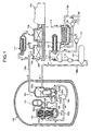
- FIG. 1 is a schematic block diagram of an exemplary nuclear power plant.
- a nuclear power plant illustrated in FIG. 1 includes a pressurized water reactor (PWR).
- PWR pressurized water reactor
- the circulation passage of primary cooling water is configured in which a nuclear reactor vessel 101, a pressurizer 102, a steam generator 103, and a primary cooling water pump 104 of the pressurized water reactor are in turn connected through a primary cooling water pipe 105 in a containment 100.
- the nuclear reactor vessel 101 is a vessel that houses a fuel assembly 120 in an enclosed state in the inside of the nuclear reactor vessel 101, which is configured of a nuclear reactor vessel main body 101a and a reactor vessel cover 101b mounted on the upper part of the nuclear reactor vessel main body 101a for inserting and removing the fuel assembly 120.
- An inlet-side nozzle 101c and an outlet-side nozzle 101d that supply and discharge light water as primary cooling water are provided on the upper part of the nuclear reactor vessel main body 101a.
- the primary cooling water pipe 105 is connected to the outlet-side nozzle 101d so as to communicate with an inlet-side channel head 103a of the steam generator 103.
- the primary cooling water pipe 105 is connected to the inlet-side nozzle 101c so as to communicate with an outlet-side channel head 103b of the steam generator 103.
- the inlet-side channel head 103a and the outlet-side channel head 103b are provided as partitioned by a partition plate 103c.
- the inlet-side channel head 103a and the outlet-side channel head 103b are partitioned from the upper side of the steam generator 103 by a tube sheet 103d provided on the ceiling portion of the inlet-side channel head 103a and the outlet-side channel head 103b.
- a heat-transfer pipe 103e in an inverted U-shape is provided on the upper side of the steam generator 103.
- the end portion of the heat-transfer pipe 103e is supported on the tube sheet 103d so as to connect the inlet-side channel head 103a to the outlet-side channel head 103b.
- the primary cooling water pipe 105 on the inlet side is connected to the inlet-side nozzle of the inlet-side channel head 103a, and the primary cooling water pipe 105 on the outlet side is connected to the outlet-side nozzle of the outlet-side channel head 103b.
- a secondary cooling water pipe 106a on the outlet side is connected to the top end on the upper side partitioned by the tube sheet 103d, and a secondary cooling water pipe 106b on the inlet side is connected to the side on the upper side.
- the circulation passage of the secondary cooling water is configured in which the steam generator 103 is connected to a steam turbine 107 through the secondary cooling water pipes 106a and 106b on the outside of the containment 100.
- the steam turbine 107 includes a high-pressure turbine 108 and a low-pressure turbine 109, and a power generator 110 is connected to the steam turbine 107. Moreover, a moisture separator heater 111 is connected to the high-pressure turbine 108 and the low-pressure turbine 109 as branched from the secondary cooling water pipe 106a. Furthermore, the low-pressure turbine 109 is connected to a condenser 112. The condenser 112 is connected to the secondary cooling water pipe 106b.
- the secondary cooling water pipe 106b is connected to the steam generator 103, goes from the condenser 112 to the steam generator 103, and is provided with a condensate pump 113, a low-pressure feed water heater 114, a deaerator 115, a main feed water pump 116, and a high-pressure feed water heater 117.
- primary cooling water is heated at the nuclear reactor vessel 101, the temperature and pressure are increased high, and the primary cooling water is pressurized at the pressurizer 102, and supplied to the steam generator 103 through the primary cooling water pipe 105 while maintaining a constant pressure.
- the steam generator 103 heat is exchanged between the primary cooling water and the secondary cooling water, and the secondary cooling water is evaporated to be steam.
- the cooled primary cooling water after heat exchange is recovered on the primary cooling water pump 104 side through the primary cooling water pipe 105, and returned to the nuclear reactor vessel 101.
- the secondary cooling water to be steam by heat exchange is supplied to the steam turbine 107.
- the steam is in the steam turbine 107, and the moisture separator heater 111 removes moisture from the exhaust air from the high-pressure turbine 108, further heats the exhaust air to be in an overheated state, and then delivers the exhaust air to the low-pressure turbine 109.
- the steam turbine 107 is driven by the steam of the secondary cooling water, and the power is transmitted to the power generator 110 for generating electric power.
- the steam used for driving the turbine is discharged to the condenser 112.
- the condenser 112 exchanges heat between the cooling water (seawater, for example) taken using a pump 112b through an intake pipe 112a and the steam discharged from the low-pressure turbine 109, condenses the steam, and returns the steam into a saturated liquid at a low pressure.
- the cooling water used for heat exchange is discharged from a drain pipe 112c. Moreover, the condensed saturated liquid is turned into secondary cooling water, and the condensate pump 113 delivers the secondary cooling water to the outside of the condenser 112 through the secondary cooling water pipe 106b.
- the secondary cooling water passing through the secondary cooling water pipe 106b is heated with low-pressure steam bled from the low-pressure turbine 109, for example, at the low-pressure feed water heater 114, impurities such as dissolved oxygen or non-condensable gas (ammonia gas) are removed from the secondary cooling water at the deaerator 115, the secondary cooling water is delivered using the main feed water pump 116, heated with high pressure steam bled from the high-pressure turbine 108, for example, at the high-pressure feed water heater 117, and returned to the steam generator 103.
- impurities such as dissolved oxygen or non-condensable gas (ammonia gas)
- FIG. 2 is a cross sectional view of a weld portion in the nuclear power plant.
- the primary cooling water pipe 105 is connected to the inlet-side nozzle 101c and the outlet-side nozzle 101d as described above. Since the materials are different between the inlet-side nozzle 101c, the outlet-side nozzle 101d, and the primary cooling water pipe 105, a safe-end pipe 121 is connected between them through a weld portion 122.
- the primary cooling water pipe 105 is connected to the inlet-side nozzle of the inlet-side channel head 103a and the outlet-side nozzle of the outlet-side channel head 103b as described above.
- the nozzles 101c and 101d are made of low-alloy steel and the primary cooling water pipe 105 is made of stainless steel, which are made of different materials, the safe-end pipe 121 made of stainless steel is disposed between them as illustrated in FIG. 2 .
- the nozzles 101c and 101d are connected to the safe-end pipe 121 with the weld portion 122 that is a different material weld portion.
- the weld portion 122 is applied with a buttering weld portion 122a made of low-alloy steel on the groove on the nozzle 101c side and the nozzle 101d side, and an overlay weld portion 122b made of low-carbon austenitic stainless steel is applied from the buttering weld portion 122a to the inner surface on the nozzle 101c side and the nozzle 101d side.
- a final weld portion 122c made of a nickel base alloy (Inconel (registered trademark), for example) is applied between the groove on the safe-end pipe 121 side and the buttering weld portion 122a to connect the nozzles 101c and 101d to the safe-end pipe 121. As described above, the weld portion 122 in FIG.
- the second is a different material weld portion in which different weld materials (the buttering weld portion 122a, the overlay weld portion 122b, and the final weld portion 122c) are joined together so as to weld different materials (the nozzles 101c and 101d and the primary cooling water pipe 105) together.
- different weld materials the buttering weld portion 122a, the overlay weld portion 122b, and the final weld portion 122c
- a water jet peening apparatus as a weld portion repairing apparatus improves tensile residual stress on the weld portion 122 to be a target and the inner surfaces of the nozzles 101c and 101d, which are the portion around the weld portion 122, to compressive residual stress, so that stress corrosion cracks are to be prevented.
- the water jet peening apparatus is an apparatus that injects high-pressure water including cavitation bubbles onto metal member surfaces in water and improves tensile residual stress on the metal member surfaces to compressive residual stress.
- the water jet peening apparatus improves tensile residual stress on the weld portion 122 and the inner surfaces of the nozzles 101c and 101d, which are the portion around the weld portion 122, to compressive residual stress
- the water jet peening apparatus is inserted into the nozzles 101c and 101d for operation.
- the processed surface is inspected in order to identify a position on the processed surface at which a water jet is injected.
- FIG. 3 is a schematic diagram of an installed state of the weld portion repairing apparatus according to the embodiment.
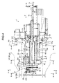
- FIG. 4 is a cross sectional side view of the weld portion repairing apparatus according to the embodiment.
- FIG. 5 is a cross sectional side view of another use form of the weld portion repairing apparatus according to the embodiment.
- FIG. 6 is a plan view of the weld portion repairing apparatus according to the embodiment.
- FIG. 7 is a cross sectional view taken along line A-A in FIGS. 4 and 6 .
- FIG. 8 is a cross sectional view taken along line B-B in FIG. 5 .
- FIG. 9 is a cross sectional view taken along line C-C in FIG. 4 .
- FIG. 10 is a diagram seen from arrow D-D in FIG. 4 .
- FIG. 11 is a diagram seen from arrow E-E in FIG. 4 .
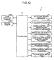
- FIG. 12 is a block diagram of the control unit of the weld portion repairing apparatus according to the embodiment.
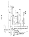
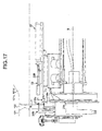
- FIGS. 13 to 17 are schematic diagrams of inspection procedures performed by the weld portion repairing apparatus according to the embodiment.
- a weld portion repairing apparatus (a water jet peening apparatus) 1 is installed as inserted into the inlet-side nozzle 101c and the outlet-side nozzle 101d, which are objects to be repaired, of the nuclear reactor vessel 101 (the nuclear reactor vessel main body 101a).
- the inlet-side nozzle 101c and the outlet-side nozzle 101d of the nuclear reactor vessel 101 are taken as examples, but the examples are not limited thereto.
- a nuclear reactor building (not illustrated in the drawings) is provided with a work floor 151, a cavity 152 is provided below the work floor 151, and cooling water is stored in this cavity 152.
- the nuclear reactor vessel 101 is disposed in the cavity 152, and hung down and supported.
- a pair of parallel guide rails 155 is laid on both sides of the cavity 152, and a mobile crane 156 is movably supported.
- the mobile crane 156 is movable in one direction in the horizontal direction (in the lateral direction in FIG. 3 ), and an electric hoist 157 is provided, which is movable in the other direction crossing (orthogonal to) one direction in the horizontal direction (in the orthogonal direction on the paper in FIG. 3 ).
- the electric hoist 157 includes a hook 158 ascendable and descendable in the vertical direction.
- An installation pole 159 is hung down through this hook 158.
- the installation pole 159 is a long member having a predetermined length, and the weld portion repairing apparatus 1 can be joined to the lower end portion of the installation pole 159.
- the installation pole 159 is configured of a plurality of split poles, in which flanges at the upper and lower ends are brought into intimate contact with each other and the split poles can be fastened with a plurality of swing bolts.
- the nozzles 101c and 101d include an opening 101f on a wall surface 101e in the inside of the nuclear reactor vessel 101, and are provided as extending in the horizontal direction (or including components in the horizontal direction).
- the weld portion repairing apparatus 1 is installed as inserted from the opening 101f into the nozzles 101c and 101d.
- the installation pole 159 is used as an installation jig for use in installation of the weld portion repairing apparatus 1.
- the installation jig is not limited to this configuration. For example, a wire, cable, and rope may be used.
- the weld portion repairing apparatus 1 includes an apparatus frame 2 joined to the installation pole 159.
- the outer shape of the apparatus frame 2 is formed in a shape insertable into the nozzles 101c and 101d, and formed in a tubular shape extending in an insertion direction T.
- the apparatus frame 2 is mainly provided with an external contact member 3, an internal contact member 4, a sucking unit 5, a contact detecting unit 6, a shooting unit 7, an injection nozzle (a repairing unit) 8, a nozzle push-out moving mechanism 9, a rotational moving mechanism 15, a slide moving mechanism 18, an inspecting unit 20, an inspecting unit push-out moving mechanism 21, a calibration test unit 22, and a calibration test unit advancing and retreating mechanism 23.
- the external contact member 3 contacts the wall surface 101e in the case where the apparatus frame 2 is inserted into at a predetermined position in the inside of the nozzles 101c and 101d.
- the external contact member 3 is mounted so as to protrude as the tip end faces the insertion tip end side (the insertion direction T side) of the apparatus frame 2 with respect to a support member 13 fixed as extending to the outside of the apparatus frame 2.
- the external contact member 3 is disposed at six locations in total, two external contact members 3 for one each at a left location and a right location on the upper side of the support member 13 and four external contact members 3 for two each at left locations and right locations on the lower side.
- the external contact members 3 at two locations on the upper side and at two locations slightly above on the lower side are configured in such a way that the position of the tip end can be changed to the insertion tip end side of the apparatus frame 2 depending on the presence or absence of a spacer 3a.
- the external contact members 3 at two locations lower on the lower side are movably configured in such a way that the position of the tip end can be changed to the insertion tip end side of the apparatus frame 2 using an actuator (a pneumatic cylinder) 3b.
- the inlet-side nozzle 101c and the outlet-side nozzle 101d are different in the shape of the opening 101f, and a projection 101g is formed on the outlet-side nozzle 101d. This is because the inlet-side nozzle 101c and the outlet-side nozzle 101d are configured to meet the presence or absence of the projection 101g.
- the external contact members 3 are provided, so that it is made possible to position the state in which the apparatus frame 2 is inserted into at a predetermined position in the inside of the nozzles 101c and 101d.
- the internal contact member 4 is provided on a portion on which the apparatus frame 2 is inserted into the nozzles 101c and 101d, and provided at a plurality of locations around the apparatus frame 2 (a center axis S), and the internal contact member 4 protrudes as the tip end faces the outside in the radial direction.
- the internal contact member 4 is disposed at seven locations in total, four internal contact members 4 disposed at four locations for two each on the left and the right above the center of the apparatus frame 2 and two each on the front and the back in the insertion direction T of the apparatus frame 2 and two internal contact members 4 disposed at two locations for one each on both sides of the height of the apparatus frame 2 near the center position as illustrated in FIG. 6 , and one internal contact member 4 disposed on the lower side of the center position of the apparatus frame 2 as illustrated in FIGS. 5 and 8 .
- the internal contact members 4 are movably configured to advance and retreat in the radial direction about the apparatus frame 2 using an actuator (a pneumatic cylinder) 4a.
- the internal contact member 4 caused to advance with the actuator 4a contacts the inner surfaces of the nozzles 101c and 101d.
- the one internal contact member 4 on the lower side is used to align the center position of the apparatus frame 2 with the center position of the inlet-side nozzle 101c.
- a tire 4b rolling in the insertion direction T is provided as an internal contact member 4 that does not advance and retreat.
- the tire 4b is used to align the center position of the apparatus frame 2 with the center position of the outlet-side nozzle 101d.
- the inlet-side nozzle 101c and the outlet-side nozzle 101d are different in the hole shape, and on the inner surface the inlet-side nozzle 101c, a slope tapered toward the inside is formed but the outlet-side nozzle 101d does not have this slope. This is because the center position of the apparatus frame 2 is aligned with the center positions of the nozzles 101c and 101d depending on the presence or absence of this slope.
- the internal contact members 4 are provided, so that it is made possible to align the center position of the apparatus frame 2 with the center positions of the nozzles 101c and 101d.
- the sucking unit 5 is provided to stick to the wall surface 101e in the case where the apparatus frame 2 is inserted into at a predetermined position in the inside of the nozzles 101c and 101d.
- the sucking unit 5 is mounted in such a way that the sucking surface faces the insertion tip end side (the insertion direction T side) of the apparatus frame 2 with respect to the support member 13.
- the sucking unit 5 is disposed at four locations in total, two sucking units 5 for one each at two locations laterally disposed on the upper side of the support member 13 and two sucking units 5 for one each at two locations laterally disposed on the lower side.
- FIG. 6 the sucking unit 5 is provided to stick to the wall surface 101e in the case where the apparatus frame 2 is inserted into at a predetermined position in the inside of the nozzles 101c and 101d.
- the sucking unit 5 is mounted in such a way that the sucking surface faces the insertion tip end side (the insertion direction T side) of the apparatus frame 2 with respect to the support member 13.
- the sucking unit 5 is movably provided in the insertion direction T using an actuator (a pneumatic cylinder) 5a. Furthermore, as illustrated in FIG. 6 , the sucking unit 5 is rockably provided in the lateral direction with respect to a rod 5b of the actuator 5a as matched with the slope of the wall surface 101e.
- the sucking units 5 are provided, so that it is made possible to maintain the state in which the apparatus frame 2 inserted into the nozzles 101c and 101d is positioned with the external contact members 3 and the state in which the center position of the apparatus frame 2 is aligned with the center positions of the nozzles 101c and 101d with the internal contact members 4.
- the contact detecting unit 6 is a unit that detects a contact in the case where the external contact member 3 contacts the wall surface 101e.
- the contact detecting unit 6 is disposed on the side of the external contact member 3 on the upper side with respect to the support member 13, and is mounted in such a way that the tip end of a contactor 6a faces the insertion tip end side (the insertion direction T side) of the apparatus frame 2.
- the contactor 6a is movably provided in the insertion direction T with respect to a casing 6b, and is spring-biased with a spring (not illustrated) so as to protrude on the insertion direction T side all the time.
- the casing 6b is provided with a proximity sensor (not illustrated) in the inside of the casing 6b, which detects a movement in the case where the contactor 6a is moved in the direction opposite to the insertion direction T.
- the contactor 6a simultaneously contacts the wall surface 101e and is moved in the direction opposite to the insertion direction T, so that the contact detecting unit 6 detects the contact and the movement with the proximity sensor, and detects that the external contact member 3 contacts the wall surface 101e.
- the contact detecting unit 6 is provided, so that it is made possible to recognize the state in which the external contact member 3 contacts the wall surface 101e, that is, to recognize that the apparatus frame 2 inserted into the nozzles 101c and 101d is positioned with the external contact members 3.
- the shooting unit 7 is disposed at four locations in total, one each at the both top and bottom and left and right of the apparatus frame 2 with respect to the support member 13.
- the shooting unit 7 includes a camera 7a and a light 7b, which are provided as facing the insertion tip end side of the apparatus frame 2 (in the insertion direction T).
- the shooting unit 7 shoots the insertion tip end side of the apparatus frame 2 inserted into the nozzles 101c and 101d from the insertion rear end side.
- the shooting unit 7 is provided, so that it is made possible to monitor the state of the apparatus frame 2 inserted into the nozzles 101c and 101d.
- the apparatus frame 2 is inserted into the nozzles 101c and 101d
- insertion is performed while minoring images shot by the shooting unit 7 with a monitor (not illustrated) disposed on the work floor 151, and it is recognized that the external contact member 3 contacts the wall surface 101e when the detection signal of the contact detecting unit 6 is inputted.
- the internal contact member 4 is caused to contact the inner surfaces of the nozzles 101c and 101d, and the sucking unit 5 is stuck to the wall surface 101e of the nozzles 101c and 101d.
- the injection nozzle 8 as a repairing unit injects a water jet to the inner surfaces of the nozzles 101c and 101d.
- the injection nozzle 8 is disposed on a support unit 14 provided on the insertion tip end side of the apparatus frame 2 in such a way that an injection port 8a to inject a water jet faces the inner surfaces of the nozzles 101c and 101d.
- the support unit 14 is rotatably supported about the center axis S of the apparatus frame 2 (the center axes of the nozzles 101c and 101d) with respect to the apparatus frame 2. More specifically, the support unit 14 is supported on the rotational moving mechanism 15.
- the rotational moving mechanism 15 includes a rotating shaft 15a. This rotating shaft 15a is mounted with the support unit 14, and is rotatably supported about the center axis S with respect to the apparatus frame 2.
- the rotating shaft 15a is formed in a cylindrical shape extending along the center axis S, and a driven gear 15b is mounted on the outer surface.
- the driven gear 15b is engaged with a drive gear 15d provided on the output shaft of a rotating motor 15c fixed to the apparatus frame 2.
- the rotational moving mechanism 15 rotates the rotating shaft 15a by transmitting the rotation of the drive gear 15d to the driven gear 15b with the drive of the rotating motor 15c.
- the support unit 14 supported on the rotating shaft 15a is rotated together with the injection nozzle 8.
- the injection nozzle 8 is rotated and moved along a predetermined moving trace about the center axis S.
- the injection nozzle 8 is disposed on the support unit 14 in such a way that the injection port 8a injecting a water jet faces the inner surfaces of the nozzles 101c and 101d. Therefore, the injection nozzle 8 that is rotated and moved with the rotational moving mechanism 15 is rotated and moved along a predetermined moving trace in the circumferential direction of the nozzles 101c and 101d while the injection port 8a faces the inner surfaces of the nozzles 101c and 101d. Namely, in the case where a vertically downward rotation angle is an angle of 0°, the orientation of the injection port 8a of the injection nozzle 8 is rotated at an angle of 360° in the circumferential direction of the nozzles 101c and 101d beyond a vertically upward rotation angle of 180°.
- the moved positions of the injection port 8a and the inspecting unit 20 (a flaw detection sensor 20A and an imaging sensor 20B), described later, on the moving trace are detected at a nozzle position detecting unit (not illustrated) provided on the rotational moving mechanism 15.
- the nozzle position detecting unit includes the rotating motor 15c as a servo motor, and thus the moved positions of the injection port 8a and the inspecting unit 20 (the flaw detection sensors 20A and the imaging sensor 20B) are detected on the moving trace.
- a high-pressure water supply pipe 16 that supplies high-pressure water to the injection nozzle 8 is disposed in the rotating shaft 15a.
- the high-pressure water supply pipe 16 is provided as extending from the insertion rear end side of the apparatus frame 2 along the center axis S in the rotating shaft 15a, and a swivel bearing 17 is provided at the extending end portion in the midway of the high-pressure water supply pipe 16.
- the high-pressure water supply pipe 16 extends upward from the swivel bearing 17, and is connected to a high-pressure water pump 160 provided on the work floor 151 for delivering high-pressure water as illustrated in FIG. 3 .
- high-pressure water delivered from the high-pressure water pump 160 is passed through the high-pressure water supply pipe 16, supplied to the injection nozzle 8, and injected as a water jet from the injection port 8a to the inner surfaces of the nozzles 101c and 101d.
- the injection nozzle 8 is then rotated about the center axis S by the rotational moving mechanism 15, and the water jet is injected to the inner surface along the circumferential direction of the nozzles 101c and 101d.
- the rotating shaft 15a is rotated by the rotational moving mechanism 15
- the high-pressure water supply pipe 16 in the inside of the rotational moving mechanism 15 is rotated together.
- the swivel bearing 17 is provided in the midway point of the high-pressure water supply pipe 16, so that the high-pressure water supply pipe 16 can be prevented from being twisted.
- the support unit 14 is slidably supported along the center axis S of the apparatus frame 2 (the center axes of the nozzles 101c and 101d) with respect to the apparatus frame 2. More specifically, the support unit 14 is supported on the slide moving mechanism 18 provided in the inside of the apparatus frame 2. As illustrated in FIGS. 4 to 6 , FIGS. 8 and 9 , the slide moving mechanism 18 includes a slide rail 18a, a slide base 18b, a slider 18c, a ball screw 18d, a nut 18e, and a slide motor 18f.
- the slide rail 18a extends in parallel with the center axis S of the apparatus frame 2, and is laterally provided in a pair.
- the slide base 18b is movably supported in the extending direction of the slide rail 18a with respect to the slide rail 18a.
- the slider 18c is mounted through the slide rail 18a, and fixed to the slide base 18b.
- the ball screw 18d is provided as extending along the center axis S of the apparatus frame 2 in parallel with the slide rail 18a, and is rotatably supported about the axis in parallel with the center axis S with respect to the apparatus frame 2. This ball screw 18d is screwed with the nut 18e.
- the slide motor 18f is joined to the ball screw 18d, and rotates the ball screw 18d.
- the ball screw 18d is rotated by the drive of the slide motor 18f, and then the slider 18c is moved in the extending direction of the ball screw 18d (in the direction in parallel with the center axis S) in association with the slide base 18b together with the nut 18e.
- the slide base 18b is mounted with the rotating shaft 15a of the foregoing rotational moving mechanism 15 for supporting the support unit 14. Namely, the rotating shaft 15a is moved in the direction in parallel with the center axis S together with the slide base 18b in association with the support unit 14 on which the injection nozzle 8 is supported. As a result, the injection nozzle 8 is slid and moved along the center axis S.
- the rotating shaft 15a is rotated about the center axis S, and mounted in a form in which the rotating shaft 15a is allowed to rotate with respect to the slide base 18b.
- the driven gear 15b is movably provided along the center axis S.
- the movement of the driven gear 15b is restricted along the center axis S in the state in which the engagement of the drive gear 15d is maintained.
- the transmission of drive to rotate the rotating shaft 15a is always maintained in sliding and moving the rotating shaft 15a by the slide moving mechanism 18.
- the rotating shaft 15a is provided in such a way that the rotating shaft 15a itself can rotate, and can slide and move along the center axis S.
- the nozzle push-out moving mechanism 9 pushes out and moves the injection nozzle 8 from the injection port 8a along the direction in which a water jet is injected.
- the nozzle push-out moving mechanism 9 is provided on the support unit 14, and includes a slide rail 9a, a slider 9b, a slide base 9c, and an actuator 9d.
- the slide rail 9a extends in the direction orthogonal to the center axis S, and is provided in a pair.
- the slider 9b is movably supported in the extending direction of the slide rail 9a.
- the slide base 9c is supported on the slider 9b, and movably provided in the extending direction of the slide rail 9a.
- the injection nozzle 8 is fixed to the slide base 9c in such a way that the injection port 8a is directed in the extending direction of the slide rail 9a.
- the actuator 9d is provided on the support unit 14 as individually disposed on the slide rails 9a, and joined to the slide base 9c.
- the actuator 9d moves the slide base 9c in the extending direction of the slide rail 9a, which is configured as a pneumatic cylinder in the embodiment.
- the actuator 9d is not limited to a pneumatic cylinder, which may be one that moves the slide base 9c in the extending direction of the slide rail 9a.
- the slide base 9c is then moved in the direction orthogonal to the center axis S together with the injection nozzle 8 by the drive of the actuator 9d.
- the injection nozzle 8 is pushed out and moved as coming close to or separating from the inner surfaces of the nozzles 101c and 101d in a form in which the injection port 8a of the injection nozzle 8 is opposite to the inner surfaces of the nozzles 101c and 101d.
- the injection distance of a water jet is set, which is a distance from the injection port 8a to the inner surfaces of the nozzles 101c and 101d.
- a predetermined distance of the injection distance of a water jet is 130 mm ⁇ 10 mm.
- the slide moving mechanism 18 causes the injection nozzle 8 to advance and retreat at a position at which the injection nozzle 8 faces a predetermined inner surface of the nozzles 101c and 101d to which the injection port 8a applies water jet peening in the state in which the apparatus frame 2 is inserted into the nozzles 101c and 101d using the external contact members 3, the internal contact members 4, and the sucking units 5.
- the nozzle push-out moving mechanism 9 pushes out and moves the injection nozzle 8 to provide an injection distance.
- the rotational moving mechanism 15 rotates and moves the injection nozzle 8 while injecting a water jet from the injection port 8a of the injection nozzle 8.
- water jet peening is applied to a predetermined inner surface of the nozzles 101c and 101d.
- the inspecting unit 20 inspects a predetermined inner surface (the weld portion 122) of the nozzles 101c and 101d to which water jet peening is applied in the embodiment. As illustrated in FIGS. 4 to 6 , the inspecting unit 20 is provided on the support unit 14. Therefore, the inspecting unit 20 is rotated and moved about the center axis S with the foregoing rotational moving mechanism 15, and slid and moved along the center axis S with the slide moving mechanism 18.
- the inspecting unit 20 includes the flaw detection sensors 20A and the imaging sensor 20B.
- the flaw detection sensor 20A contacts the inner surfaces of the nozzles 101c and 101d for flaw detection inspection.
- the flaw detection sensor 20A is an eddy current flaw detection sensor, which is rotated and moved about the center axis S with the rotational moving mechanism 15, and moved along the circumferential direction with respect to the inner surfaces of the nozzles 101c and 101d for flaw detection.
- two flaw detection sensors 20A are provided as arranged side by side along the inner surfaces of the nozzles 101c and 101d in the circumferential direction, which are inspection targets in the embodiment.
- the imaging sensor 20B shoots the inner surfaces of the nozzles 101c and 101d for visual inspection, which is rotated and moved about the center axis S with the rotational moving mechanism 15, and moved along the circumferential direction with respect to the inner surfaces of the nozzles 101c and 101d for shooting.
- the inspecting unit 20 includes a light to illuminate a portion to be shot by the imaging sensor 20B, although not clearly illustrated in the drawings.
- the inspecting unit push-out moving mechanism 21 pushes out and moves the inspecting unit 20 toward the inner surfaces of the nozzles 101c and 101d.
- the inspecting unit push-out moving mechanism 21 is provided on the support unit 14, and includes a slide rail 21a, a slider 21b, a slide base 21c, and an actuator 21d.
- the slide rail 21a extends in the direction orthogonal to the center axis S, and is provided in a pair, and formed as the slide rail 9a of the foregoing nozzle push-out moving mechanism 9 is extended.
- the slider 21b is movably supported in the extending direction of the slide rail 21a.
- the slide base 21c is supported on the slider 21b, and movably provided in the extending direction of the slide rail 21a.
- the flaw detection sensors 20A (see FIG. 11 ) and the imaging sensor 20B, which are the inspecting unit 20, are mounted on the slide base 21c.
- the actuator 21d is provided on the support unit 14 as disposed on the side of one of the slide rails 21a, and is joined to the slide base 21c.
- the actuator 21d moves the slide base 21c in the extending direction of the slide rail 21a, which is configured as a pneumatic cylinder in the embodiment.
- the actuator 21d is not limited to a pneumatic cylinder, which may be one that moves the slide base 21c in the extending direction of the slide rail 21a.
- the slide base 21c is moved in the direction orthogonal to the center axis S together with the inspecting unit 20 (the flaw detection sensors 20A and the imaging sensor 20B) by the drive of the actuator 21d.
- the pushing-out and moving direction is the direction in which the inspecting unit 20 performs inspection, which is a direction in which a face contacting the inner surfaces of the nozzles 101c and 101d is directed in the case of the flaw detection sensor 20A, whereas which is a direction in which the imaging sensor 20B shoots the inner surfaces of the nozzles 101c and 101d in the case of the imaging sensor 20B.
- the inspecting unit push-out moving mechanism 21 pushes out and moves the inspecting unit 20 in such a way that the inspecting unit 20 comes close to or separates from the inner surfaces of the nozzles 101c and 101d.
- the inspecting unit push-out moving mechanism 21 includes a flaw detection sensor push-out moving mechanism 21A that pushes out and moves the flaw detection sensor 20A alone and an imaging sensor push-out moving mechanism 21B that pushes out and moves the imaging sensor 20B alone.
- the flaw detection sensor push-out moving mechanism 21A is provided on the slide base 21c, and includes a fixed base 21Aa, a slide rail 21Ab, a slider 21Ac, an actuator 21Ad, and a slide base 21Ae.
- the fixed base 21Aa is fixed to the slide base 21c.
- the slide rail 21Ab is provided in a pair in parallel with the slide rail 9a, and extends in the direction orthogonal to the center axis S (see FIGS. 4 to 6 ).
- the slider 21Ac is movably supported in the extending direction of the slide rail 21Ab.
- the actuator 21Ad is fixed to the fixed base 21Aa, and joined to the slide base 21Ae.
- the actuator 21Ad moves the slide base 21Ae in the extending direction of the slide rail 21Ab, which is configured as a pneumatic cylinder in the embodiment.
- the actuator 21Ad is not limited to a pneumatic cylinder, which may be one that moves the slide base 21Ae in the extending direction of the slide rail 21Ab.
- the slide base 21Ae supports the flaw detection sensor 20A.
- Two flaw detection sensors 20A are provided as arranged side by side along the inner surfaces of the nozzles 101c and 101d in the circumferential direction, which are targets for inspection, as described above, and the flaw detection sensors 20A are supported on first sensor support units 20Aa so as to individually tilt in the circumferential direction.
- the first sensor support units 20Aa are integrally mounted on a sensor base 20Ab.
- Both ends of the sensor base 20Ab are supported on a second sensor support unit 20Ac in such a way that the sensor base 20Ab tilts about an axis orthogonal to the slide rail 21Ab in the extending direction of the center axis S.
- This second sensor support unit 20Ac is mounted on the slide base 21Ae.
- the second sensor support unit 20Ac is movably provided on the slide base 21Ae in the extending direction of the slide rail 21Ab, and is elastically supported with a spring (not illustrated).
- the flaw detection sensor 20A is supported in such a way that the flaw detection sensor 20A freely tilts in the circumferential direction and in the extending direction of the center axis S with the first sensor support unit 20Aa and the second sensor support unit 20Ac and is spring-biased with the spring to follow the shape of the inner surfaces of the nozzles 101c and 101d and contact the inner surfaces of the nozzles 101c and 101d.
- the slide base 21Ae is pushed out and moved in the direction orthogonal to the center axis S together with the flaw detection sensor 20A by the drive of the actuator 21Ad.
- the imaging sensor push-out moving mechanism 21B is provided on the slide base 21c, and includes an actuator 21Ba and a slide base 21Bb.
- the actuator 21Ba is fixed to the slide base 21c, and joined to the slide base 21Bb.
- the actuator 21Ba moves the slide base 21Bb in the extending direction of the slide rail 21a, which is configured as a pneumatic cylinder in the embodiment.
- the actuator 21Ba is not limited to a pneumatic cylinder, which may be one that moves the slide base 21Bb in the extending direction of the slide rail 21a.
- the slide base 21Bb supports the imaging sensor 20B. In the imaging sensor push-out moving mechanism 21B, the slide base 21Bb is pushed out and moved in the direction orthogonal to the center axis S together with the imaging sensor 20B by the drive of the actuator 21Ba.
- the calibration test unit 22 calibrates and tests the inspecting unit 20 (the flaw detection sensors 20A and the imaging sensor 20B). As illustrated in FIGS. 4 to 6 , the calibration test unit 22 is provided on the calibration test unit advancing and retreating mechanism 23.
- the calibration test unit 22 includes flaw detection sensor calibration test specimens 22A that calibrate the flaw detection sensors 20A and an imaging sensor calibration test specimen 22B that calibrates the imaging sensor 20B.
- the calibration test unit advancing and retreating mechanism 23 advances and retreats the calibration test unit 22 in the direction along the center axis S. As illustrated in FIGS. 4 to 6 , the calibration test unit advancing and retreating mechanism 23 is provided on the apparatus frame 2. Therefore, the calibration test unit advancing and retreating mechanism 23 and the calibration test unit 22 are not involved in rotation and movement of the foregoing rotational moving mechanism 15 and sliding and movement of the slide moving mechanism 18.
- the calibration test unit advancing and retreating mechanism 23 includes a fixed base 23a, a slide rail 23b, a slide base 23c, and an actuator 23d.
- the fixed base 23a is fixed to the apparatus frame 2.
- the slide rail 23b extends in parallel with the center axis S, and is provided in a pair.
- the slide base 23c supports the calibration test unit 22, and is movably provided in the extending direction of the slide rail 23b.
- the actuator 23d is fixed to the fixed base 23a, and joined to the slide base 23c.
- the actuator 23d moves the slide base 23c in the extending direction of the slide rail 23b, which is configured as a pneumatic cylinder in the embodiment.
- the actuator 23d is not limited to a pneumatic cylinder, which may be one that moves the slide base 23c in the extending direction of the slide rail 23b.
- the slide base 23c is advanced and retreated on a linear trace in parallel with the center axis S together with the calibration test unit 22 (the flaw detection sensor calibration test specimens 22A and the imaging sensor calibration test specimen 22B) by the drive of the actuator 23d (see FIGS. 13 to 17 ).
- the calibration test unit 22 supported on the slide base 23c is disposed in such a way that the positions of the flaw detection sensor calibration test specimens 22A and the imaging sensor calibration test specimen 22B are matched with the positions at which the flaw detection sensors 20A and the imaging sensor 20B of the foregoing inspecting unit 20 face the inner surfaces of the nozzles 101c and 101d, which are targets for inspection, in the vertical upward direction of the apparatus frame 2.
- the positions of the flaw detection sensor calibration test specimens 22A and the imaging sensor calibration test specimen 22B are matched with the positions at which the flaw detection sensors 20A and the imaging sensor 20B of the foregoing inspecting unit 20 face the inner surfaces of the nozzles 101c and 101d, which are targets for inspection, in the vertical upward direction of the apparatus frame 2.
- the flaw detection sensor calibration test specimens 22A and the imaging sensor calibration test specimen 22B are matched with the positions at which the flaw detection sensors 20A and the imaging sensor 20B face the inner surfaces of the nozzles 101c and 101d, which are targets for inspection, on the trace of pushing out and moving the inspecting unit 20 (the flaw detection sensors 20A and the imaging sensor 20B) in the state in which the flaw detection sensor calibration test specimens 22A and the imaging sensor calibration test specimen 22B are advanced by the calibration test unit advancing and retreating mechanism 23.
- the calibration test unit 22 is disposed in such a way that the imaging sensor 20B is located as matched with the position of a distance L2, which is the same as a distance L1 in shooting the inner surfaces of the nozzles 101c and 101d, in the state in which the calibration test unit 22 is advanced by the calibration test unit advancing and retreating mechanism 23.
- the weld portion repairing apparatus 1 includes a control unit 25.
- the control unit 25 controls the operation of the weld portion repairing apparatus 1.
- FIG. 12 is a control system for inspection and repairing.
- the control unit 25 controls the rotating motor 15c of the rotational moving mechanism 15, the slide motor 18f of the slide moving mechanism 18, the actuator 23d of the calibration test unit advancing and retreating mechanism 23, the actuator 21d of the inspecting unit push-out moving mechanism 21, the actuator 21Ad of the flaw detection sensor push-out moving mechanism 21A, the actuator 21Ba of the imaging sensor push-out moving mechanism 21B, the actuator 9d of the nozzle push-out moving mechanism 9, and the high-pressure water pump 160.
- the control unit 25 is connected to the flaw detection sensors 20A and the imaging sensor 20B, outputs drive signals to the sensors 20A and 20B, and receives detection signals from the sensors 20A and 20B.
- the control unit 25 determines a weld boundary position (a different material weld boundary position) ⁇ on the weld portion 122 using the detection signal received from the flaw detection sensor 20A.
- the weld boundary position ⁇ is a boundary position between the buttering weld portion 122a and the overlay weld portion 122b on the inner surfaces of the nozzles 101c and 101d.
- a determination is made based on the description in Japanese Patent No. 4885068 .
- the control unit 25 sets a flaw detection inspection range WA by the flaw detection sensor 20A of the inspecting unit 20 with reference to the determined weld boundary position ⁇ .
- the flaw detection inspection range WA is set in such a way that reference is made to the weld boundary position ⁇
- a predetermined reference inspection range WAa is determined, which is an inspection reference, on the nozzle 101c side and the nozzle 101d side from the weld boundary position ⁇ based on the design drawings in applying the weld portion 122
- a requested inspection range WAb is determined, which includes the reference inspection range WAa and is requested for inspection, on the safe-end pipe 121 side.
- the flaw detection inspection range WA is set in such a way that a margin WAc is provided on both sides of the requested inspection range WAb.
- control unit 25 sets a visual inspection range WB by the imaging sensor 20B of the inspecting unit 20 with reference to the weld boundary position ⁇ .
- the visual inspection range WB is set in such a way that the requested inspection range WAb in the flaw detection inspection range WA is set as the visual inspection range WB because the weld boundary position ⁇ can be identified.
- the control unit 25 sets a repair range (a water jet application range) WC by the injection nozzle 8, which is a repairing unit, with reference to the weld boundary position ⁇ .
- a repair range (a water jet application range) WC by the injection nozzle 8, which is a repairing unit, with reference to the weld boundary position ⁇ .
- ranges WCa and WCb are set at which the outer edge of a circular application range of a water jet is positioned from the weld boundary position ⁇ to the nozzle 101c side and the nozzle 101d side in such a way that a circular application range of a water jet is an effective range for application and the center of the circular application range of a water jet is matched with a center C of a range including the buttering weld portion 122a and the final weld portion 122c based on the design drawings in applying the weld portion 122.
- the weld portion repairing apparatus uses a manipulator that supports a grindstone, although not clearly illustrated in the drawings.
- a depth D is requested to cut the weld portion 122 from the weld boundary position ⁇ so as to leave the overlay weld portion 122b.
- the control unit sets a cutting range indicated by an alternate long and short dash line in FIG. 2 in such a way that the depth D is provided with reference to the weld boundary position ⁇ .
- FIGS. 13 to 17 illustrate the state in which the apparatus frame 2 is inserted into and positioned at a predetermined position in the inside of the nozzles 101c and 101d with the external contact members 3, the center position (the center axis S) of the apparatus frame 2 is matched with the center positions of the nozzles 101c and 101d with the internal contact members 4, and this state is maintained by the sucking units 5.
- the rotational moving mechanism 15 is set in such a way that the flaw detection sensors 20A and the imaging sensor 20B of the inspecting unit 20 are at positions (reference positions) facing the vertical upward direction of the apparatus frame 2.
- the flaw detection sensor 20A performs flaw detection inspection.
- the slide moving mechanism 18 slides and moves the flaw detection sensors 20A of the inspecting unit 20 in parallel with the center axis S in such a way that the flaw detection sensors 20A are located at the vertical downward position of the weld portion 122.
- the calibration test unit advancing and retreating mechanism 23 advances the calibration test unit 22.
- the flaw detection sensor calibration test specimens 22A are disposed on the trace on which the flaw detection sensors 20A are pushed out and moved to the inner surfaces of the nozzles 101c and 101d at the reference position at which the weld portion repairing apparatus 1 is inserted into the nozzles 101c and 101d.
- the flaw detection sensor push-out moving mechanism 21A pushes out and moves the flaw detection sensors 20A in the direction orthogonal to the center axis S to contact the flaw detection sensor calibration test specimens 22A.
- the rotational moving mechanism 15 rotates and moves the flaw detection sensors 20A about the center axis S to subject the flaw detection sensor calibration test specimens 22A to flaw detection.
- the flaw detection sensors 20A are calibrated and tested based on the flaw detection sensor calibration test specimens 22A.
- the calibration test unit advancing and retreating mechanism 23 causes the calibration test unit 22 to retreat.
- the inspecting unit push-out moving mechanism 21 and the flaw detection sensor push-out moving mechanism 21A push out and move the flaw detection sensors 20A in the direction orthogonal to the center axis S, and cause the flaw detection sensors 20A to contact the inner surfaces of the nozzles 101c and 101d (the weld portion 122).
- the slide moving mechanism 18 slides and moves the flaw detection sensors 20A in parallel with the center axis S.
- the weld boundary position ⁇ on the weld portion 122 is determined using the detection signals of the flaw detection sensors 20A.
- the flaw detection inspection range WA is set with reference to the weld boundary position ⁇ .
- the rotational moving mechanism 15 rotates and moves the flaw detection sensors 20A about the center axis S, and the inner surfaces of the nozzles 101c and 101d including the weld portion 122 are subjected to flaw detection.
- the flaw detection sensors 20A perform flaw detection inspection.
- calibrations and tests are performed after inspection of the flaw detection sensors 20A based on the flaw detection sensor calibration test specimens 22A.
- the detected data of flaw detection inspection is analyzed, and the weld boundary position ⁇ is confirmed.
- the imaging sensor 20B performs visual inspection.
- the visual inspection range WB is set with reference to the weld boundary position ⁇ determined and confirmed in flaw detection inspection.
- the slide moving mechanism 18 slides and moves the imaging sensor 20B of the inspecting unit 20 in parallel with the center axis S in such a way that the imaging sensor 20B is located at the vertical downward position of the weld portion 122.
- the calibration test unit advancing and retreating mechanism 23 advances the calibration test unit 22.
- the imaging sensor calibration test specimen 22B is disposed on the trace on which the imaging sensor 20B is pushed out and moved to the inner surfaces of the nozzles 101c and 101d at the reference position at which the weld portion repairing apparatus 1 is inserted into the nozzles 101c and 101d. Therefore, the imaging sensor 20B is calibrated and tested based on the imaging sensor calibration test specimen 22B. Subsequently, as illustrated in FIG. 17 , the calibration test unit advancing and retreating mechanism 23 causes the calibration test unit 22 to retreat. Subsequently, the inspecting unit push-out moving mechanism 21 and the imaging sensor push-out moving mechanism 21B push out and move the imaging sensor 20B in the direction orthogonal to the center axis S.
- the rotational moving mechanism 15 rotates and moves the imaging sensor 20B about the center axis S to shoot the inner surfaces of the nozzles 101c and 101d including the weld portion 122.
- visual inspection is performed with images shot by the imaging sensor 20B.
- calibrations and tests are performed after inspection of the imaging sensor 20B based on the imaging sensor calibration test specimen 22B.
- the injection nozzle 8 which is a repairing unit, is used for repairing.
- the repair range WC is set with reference to the weld boundary position ⁇ determined and confirmed in flaw detection inspection.
- the slide moving mechanism 18 slides and moves the injection port 8a of the injection nozzle 8 in parallel with the center axis S in such a way that the injection port 8a is directed to the weld portion 122.
- the nozzle push-out moving mechanism 9 pushes out and moves the injection nozzle 8 in the direction orthogonal to the center axis S.
- the injection distance of a water jet is set, which is a distance from the injection port 8a to the inner surfaces of the nozzles 101c and 101d including the weld portion 122.
- the high-pressure water pump 160 is driven to inject high-pressure water from the injection port 8a of the injection nozzle 8, and the rotational moving mechanism 15 rotates the injection nozzle 8 about the center axis S.
- a water jet is injected along the circumferential direction of the inner surfaces of the nozzles 101c and 101d including the weld portion 122, and the water jet improves tensile residual stress on the inner surfaces of the nozzles 101c and 101d including the weld portion 122 to compressive residual stress.
- the imaging sensor 20B subjects the location repaired with the water jet to visual inspection for confirmation.
- the weld portion repairing method is the weld portion repairing method for repairing the weld portion 122 provided on the nuclear power plant, including: determining the weld boundary position ⁇ on the weld portion 122 using the detection signals of the flaw detection sensors 20A; setting the repair range WC with reference to the weld boundary position ⁇ ; and repairing the repair range WC.
- the repair range WC is set with reference to the weld boundary position ⁇ determined using the flaw detection sensors 20A, so that it is possible to perform accurate repairing.
- the weld portion repairing method according to the embodiment is the weld portion repairing method for repairing the weld portion 122 provided on the nuclear power plant, including: determining the weld boundary position ⁇ on the weld portion 122 using the detection signals of the flaw detection sensors 20A; setting the flaw detection inspection range WA with reference to the weld boundary position ⁇ using the flaw detection sensors 20A; inspecting the flaw detection inspection range WA using the flaw detection sensors 20A; setting the repair range WC on the repair location subjected to inspection with reference to the weld boundary position ⁇ ; and repairing the repair range WC.
- the flaw detection inspection range WA and the repair range WC are set with reference to the weld boundary position ⁇ determined by flaw detection inspection, so that it is possible to perform accurate flaw detection inspection and repairing with no displacement between both of the ranges.
- the weld portion repairing method according to the embodiment further includes: setting the visual inspection range WB using the imaging sensor 20B with reference to the weld boundary position ⁇ ; and inspecting the visual inspection range WB using the imaging sensor 20B.
- the visual inspection range WB is set with reference to the weld boundary position ⁇ determined by flaw detection inspection, so that it is possible to perform accurate visual inspection also in visual inspection with no displacement in the flaw detection inspection range or in the repair range.
- the weld portion 122 is a different material weld portion in which different weld materials (the buttering weld portion 122a, the overlay weld portion 122b, and the final weld portion 122c) are joined together so as to weld different materials (the nozzles 101c and 101d, and the primary cooling water pipe 105) together.
- the flaw detection sensors 20A are used to detect the different material weld boundary position ⁇ , so that it is possible to accurately detect the different material weld boundary position ⁇ .
- the weld portion repairing apparatus 1 is the weld portion repairing apparatus 1 that repairs the weld portion 122 provided on the nuclear power plant, including the apparatus frame 2 disposed at the position of the weld portion 122, the flaw detection sensor 20A provided on the apparatus frame 2, the injection nozzle (the repairing unit) 8 that is provided on the apparatus frame 2 and repairs the weld portion 122, and the control unit 25 that controls determining the weld boundary position ⁇ on the weld portion 122 using the detection signals of the flaw detection sensors 20A, setting the repair range WC with reference to the weld boundary position ⁇ , and repairing the repair range WC using the injection nozzle 8.
- the repair range WC is set with reference to the weld boundary position ⁇ determined using the flaw detection sensors 20A, so that it is possible to perform accurate repairing.
- the weld portion repairing apparatus 1 is the weld portion repairing apparatus 1 that repairs the weld portion 122 provided on the nuclear power plant, including the apparatus frame 2 disposed at the position of the weld portion 122, the inspecting unit 20 that performs flaw detection inspection on the weld portion 122 using the flaw detection sensors 20A provided on the apparatus frame 2, the injection nozzle (the repairing unit) 8 that is provided on the apparatus frame 2 and repairs the repair location subjected to flaw detection inspection by the inspecting unit 20, and the control unit 25 that controls determining the weld boundary position ⁇ on the weld portion 122 using the detection signals of the flaw detection sensors 20A of the inspecting unit 20, setting the flaw detection inspection range WA using the flaw detection sensors 20A with reference to the weld boundary position ⁇ , subjecting the flaw detection inspection range WA to flaw detection inspection using the flaw detection sensors 20A, setting the repair range WC on the repair location subjected to flaw detection inspection with reference to the weld boundary position
- the flaw detection inspection range WA and the repair range WC are set with reference to the weld boundary position ⁇ determined by flaw detection inspection, so that it is possible to perform accurate flaw detection inspection and repairing with no displacement between both of the ranges.
- the weld portion repairing apparatus it is possible to set both of the ranges according to the criteria involved in both of inspection and repairing and to inspect and repair the weld portion 122.
- the inspecting unit 20 includes the imaging sensor 20B that performs visual inspection on the weld portion 122.
- the control unit 25 controls setting the visual inspection range WB using the imaging sensor 20B with reference to the weld boundary position ⁇ and subjecting the visual inspection range WB to visual inspection using the imaging sensor 20B.
- the visual inspection range WB is set with reference to the weld boundary position ⁇ determined by flaw detection inspection, so that it is possible to perform accurate visual inspection also in visual inspection with no displacement in the flaw detection inspection range or in the repair range.
- the apparatus frame is configured as a manipulator, and the manipulator is mounted with the inspecting unit and the repairing unit, although not clearly illustrated in the drawings.
- the repairing unit may perform shot peening or inlay work, not limited to water jet peening.
- the weld portion 122 is not limited to the foregoing different material weld portion.
- the welded joint between the safety injection nozzle and the safe-end is a different material weld portion.
- the joint is a stainless steel weld portion made of the same material, not made of different materials.
- the same material weld portion generally includes weld penetration beads on the inner surface to easily tell the weld boundary position. However, it is not enabled to apply flaw detection inspection because of the penetration beads.
- the weld boundary position is measured by visual inspection, and repaired by water jet peening.
- some nuclear power plants have penetration beads smoothly machined.
- the weld boundary position can be confirmed by flaw detection inspection before repaired, and the weld portion repairing method and the weld portion repairing apparatus according to the embodiment can be applied.
Landscapes
- Engineering & Computer Science (AREA)
- Physics & Mathematics (AREA)
- High Energy & Nuclear Physics (AREA)
- General Engineering & Computer Science (AREA)
- Plasma & Fusion (AREA)
- Chemical & Material Sciences (AREA)
- Life Sciences & Earth Sciences (AREA)
- Health & Medical Sciences (AREA)
- General Health & Medical Sciences (AREA)
- General Physics & Mathematics (AREA)
- Immunology (AREA)
- Pathology (AREA)
- Analytical Chemistry (AREA)
- Biochemistry (AREA)
- Electrochemistry (AREA)
- Chemical Kinetics & Catalysis (AREA)
- Mechanical Engineering (AREA)
- Monitoring And Testing Of Nuclear Reactors (AREA)
- Investigating Or Analyzing Materials By The Use Of Magnetic Means (AREA)
- Butt Welding And Welding Of Specific Article (AREA)
Abstract
Description
- The present invention relates to a weld portion repairing method and a weld portion repairing apparatus that repair a weld portion.
- For example, in a nuclear power plant equipped with a pressurized water reactor (PWR), light water as primary cooling water is used as a nuclear reactor primary coolant and a neutron moderator, the light water is turned into high-temperature and high-pressure water that is not boiled for the entire reactor internal, the high-temperature and high-pressure water is delivered to a steam generator for generating steam by heat exchange, and the steam is delivered to a turbine generator for generating power.
- In such a nuclear power plant, it is necessary to inspect a pressurized water reactor on various structures, for example, on a regular basis in order to secure sufficient safety and reliability. In the case where a problem is found through inspections, necessary portions related to the problem are repaired. For example, in the pressurized water reactor, a nuclear reactor vessel main body is provided with an outlet-side nozzle that supplies primary cooling water to the steam generator and an inlet-side nozzle that takes in primary cooling water subjected to heat exchange at the steam generator. On the other hand, the steam generator is provided with an inlet-side nozzle that takes the primary cooling water supplied from the nuclear reactor in a channel head and an outlet-side nozzle that returns the primary cooling water subjected to heat exchange to the nuclear reactor. In the nuclear reactor and the steam generator, the inlet-side nozzle is joined to exchange to the nuclear reactor. In the nuclear reactor and the steam generator, the inlet-side nozzle is joined to the outlet-side nozzle through a primary cooling water pipe. Since the materials are different as the nozzles are made of low-alloy steel and the primary cooling water pipe is made of stainless steel, a stainless steel safe-end pipe is disposed between the nozzles and the primary cooling water pipe. A weld portion joins the nozzle to the safe-end pipe, a buttering weld portion is provided on the groove on the nozzle side, and an overlay weld portion is provided on the inner surface from the buttering weld portion to the nozzle side. The weld portion between the nozzle and the safe-end pipe is inspected on a regular basis, and is repaired as necessary.
- For example, in a method and apparatus for cutting the nozzle inner surface of a nuclear vessel described in
Patent Literature 1, in the case where a surface defect such as a crack is found on the weld portion of a nozzle because of aged deterioration, a cutting apparatus is inserted into the nozzle and positioned at a cutting position, and then the weld portion is cut.Patent Literature 1 describes that in cutting, the cutting position is determined using an eddy current flaw detector sensor, an inner surface form of the nozzle is recorded using a displacement detector sensor, and the inner surface of the nozzle is cut based on these items of data. - Moreover, an eddy current flaw detector and an eddy current flaw detection method described in
Patent Literature 2 describe that the detector includes an eddy current flaw detection probe, a magnetic saturation eddy current flaw detection probe that includes a magnet and reduces noise caused by changes in permeability, and an analyzing unit that compares and analyzes signal waveforms obtained by scanning the same location using the eddy current flaw detection probe and the magnetic saturation eddy current flaw detection probe and determines whether the signal waveforms are caused by a flow of a sample that is a measurement object or caused by noise. Furthermore, in the eddy current flaw detector and the eddy current flaw detection method described inPatent Literature 2, the analyzing unit determines the position of a different material weld boundary that is a boundary between different materials on the sample that is a measurement object based on the signal value distribution of the sample using the magnetic saturation eddy current flaw detection probe, and extracts and sizes a defect according to the signal waveform of the eddy current flaw detection probe or the magnetic saturation eddy current flaw detection probe based on the different material weld boundary position. -
- Patent Literature 1: Japanese Laid-open Patent Publication No.
2006-349596 - Patent Literature 2: Japanese Laid-open Patent Publication No.
2008-309573 - As described in
Patent Literature 2, it is known that the weld boundary position is determined and eddy current flaw detection inspection is performed based on the weld boundary position. However, also in repairing as inPatent Literature 1, it is necessary to set a range for inspection, and it is desired to set a repair range according to criteria related to inspection for repairing an accurate position. - The present invention is to solve the problems, and it is an object to provide a weld portion repairing method and a weld portion repairing apparatus that can appropriately set a repair range and repair a weld portion. Solution to Problem
- According to an aspect of the present invention, a weld portion repairing method for repairing a weld portion provided on a nuclear power plant includes: determining a weld boundary position on the weld portion using a detection signal of a flaw detection sensor; setting a repair range with reference to the weld boundary position; and repairing the repair range.
- According to the weld portion repairing method, the repair range is set with reference to the weld boundary position determined using the flaw detection sensor, so that it is possible to perform accurate repairing.
- According to another aspect of the present invention, a weld portion repairing method for repairing a weld portion provided on a nuclear power plant includes: determining a weld boundary position on the weld portion using a detection signal of a flaw detection sensor; setting a flaw detection inspection range using the flaw detection sensor with reference to the weld boundary position; inspecting the flaw detection inspection range using the flaw detection sensor; setting a repair range on the repair location subjected to inspection with reference to the weld boundary position; and repairing the repair range.
- According to the weld portion repairing method, the flaw detection inspection range and the repair range are set with reference to the weld boundary position determined by flaw detection inspection, so that it is possible to perform accurate flaw detection inspection and repairing with no displacement between both of the ranges. As described above, in accordance with the weld portion repairing method according to the present invention, it is possible to set both of the ranges according to the criteria involved in both of inspection and repairing and to inspect and repair the weld portion.
- Advantageously, the weld portion repairing method further includes: setting a visual inspection range using an imaging sensor with reference to the weld boundary position; and inspecting the visual inspection range using the imaging sensor.
- According to the weld portion repairing method, the visual inspection range is set with reference to the weld boundary position determined by flaw detection inspection, so that it is possible to perform accurate visual inspection also in visual inspection with no displacement in the flaw detection inspection range or in the repair range.
- Advantageously, in the weld portion repairing method, the weld portion is a different material weld portion in which different weld materials are joined so as to weld different materials together.
- Since the surface of the different material weld portion is machined, it is difficult to determine a different material weld boundary position by visual confirmation. Therefore, the different material weld boundary position is detected using the flaw detection sensor, so that it is possible to accurately detect the different material weld boundary position.
- According to still another aspect of the present invention, a weld portion repairing apparatus for repairing a weld portion provided on a nuclear power plant includes: an apparatus frame disposed at a position of the weld portion; a flaw detection sensor provided on the apparatus frame; a repairing unit provided on the apparatus frame and configured to repair the weld portion; and a control unit configured to control determining a weld boundary position on the weld portion using a detection signal of the flaw detection sensor, setting a repair range with reference to the weld boundary position, and repairing the repair range using the repairing unit.
- According to the weld portion repairing apparatus, the repair range is set with reference to the weld boundary position determined using the flaw detection sensor, so that it is possible to perform accurate repairing.
- According to still another aspect of the present invention, a weld portion repairing apparatus for repairing a weld portion provided on a nuclear power plant includes: an apparatus frame disposed at a position of the weld portion; an inspecting unit provided on the apparatus frame and configured to perform flaw detection inspection on the weld portion using a flaw detection sensor; a repairing unit provided on the apparatus frame and configured to repair a repair location subjected to flaw detection inspection using the inspecting unit; and a control unit configured to control determining a weld boundary position on the weld portion using a detection signal of the flaw detection sensor of the inspecting unit, setting a flaw detection inspection range using the flaw detection sensor with reference to weld boundary position, subjecting the flaw detection inspection range to flaw detection inspection using the flaw detection sensor, setting a repair range on the repair location subjected to flaw detection inspection with reference to the weld boundary position, and repairing the repair range using the repairing unit.
- According to the weld portion repairing apparatus, the flaw detection inspection range and the repair range are set with reference to the weld boundary position determined by flaw detection inspection, so that it is possible to perform accurate flaw detection inspection and repairing with no displacement between both of the ranges. As described above, in accordance with the weld portion repairing apparatus according to the present invention, it is possible to set both of the ranges according to the criteria involved in both of inspection and repairing and to inspect and repair the weld portion.
- Advantageously, in the weld portion repairing apparatus, the inspecting unit includes an imaging sensor configured to perform visual inspection on the weld portion, and the control unit controls setting a visual inspection range using the imaging sensor with reference to the weld boundary position and subjecting the visual inspection range to visual inspection using the imaging sensor.
- According to the weld portion repairing apparatus, the visual inspection range is set with reference to the weld boundary position determined by flaw detection inspection, so that it is possible to perform accurate visual inspection also in visual inspection with no displacement in the flaw detection inspection range or in the repair range.
- According to the present invention, it is possible to appropriately set a repair range and to repair a weld portion.
-
-
FIG. 1 is a schematic block diagram of an exemplary nuclear power plant; -
FIG. 2 is a cross sectional view of a weld portion in the nuclear power plant; -
FIG. 3 is a schematic diagram of an installed state of a weld portion repairing apparatus according to an embodiment of the present invention; -
FIG. 4 is a cross sectional side view of the weld portion repairing apparatus according to the embodiment of the present invention; -
FIG. 5 is a cross sectional side view of another use form of the weld portion repairing apparatus according to the embodiment of the present invention; -
FIG. 6 is a plan view of the weld portion repairing apparatus according to the embodiment of the present invention; -
FIG. 7 is a cross sectional view taken along line A-A inFIGS. 4 and6 ; -
FIG. 8 is a cross sectional view taken along line B-B inFIG. 5 ; -
FIG. 9 is a cross sectional view taken along line C-C inFIG. 4 ; -
FIG. 10 is a diagram seen from arrow D-D inFIG. 4 ; -
FIG. 11 is a diagram seen from arrow E-E inFIG. 4 ; -
FIG. 12 is a block diagram of a control unit of the weld portion repairing apparatus according to the embodiment of the present invention; -
FIG. 13 is a schematic diagram of inspection procedures performed by the weld portion repairing apparatus according to the embodiment of the present invention; -
FIG. 14 is a schematic diagram of inspection procedures performed by the weld portion repairing apparatus according to the embodiment of the present invention; -
FIG. 15 is a schematic diagram of inspection procedures performed by the weld portion repairing apparatus according to the embodiment of the present invention; -
FIG. 16 is a schematic diagram of inspection procedures performed by the weld portion repairing apparatus according to the embodiment of the present invention; and -
FIG. 17 is a schematic diagram of inspection procedures performed by the weld portion repairing apparatus according to the embodiment of the present invention. - In the following, an embodiment of the present invention will be described in detail with reference to the drawings. It is noted that the present invention is not limited to this embodiment. Moreover, components in the embodiment below include ones easily replaceable by a person skilled in the art or ones substantially the same.
-
FIG. 1 is a schematic block diagram of an exemplary nuclear power plant. A nuclear power plant illustrated inFIG. 1 includes a pressurized water reactor (PWR). In the nuclear power plant, the circulation passage of primary cooling water is configured in which anuclear reactor vessel 101, apressurizer 102, asteam generator 103, and a primarycooling water pump 104 of the pressurized water reactor are in turn connected through a primarycooling water pipe 105 in acontainment 100. - The
nuclear reactor vessel 101 is a vessel that houses afuel assembly 120 in an enclosed state in the inside of thenuclear reactor vessel 101, which is configured of a nuclear reactor vesselmain body 101a and areactor vessel cover 101b mounted on the upper part of the nuclear reactor vesselmain body 101a for inserting and removing thefuel assembly 120. An inlet-side nozzle 101c and an outlet-side nozzle 101d that supply and discharge light water as primary cooling water are provided on the upper part of the nuclear reactor vesselmain body 101a. The primarycooling water pipe 105 is connected to the outlet-side nozzle 101d so as to communicate with an inlet-side channel head 103a of thesteam generator 103. Moreover, the primarycooling water pipe 105 is connected to the inlet-side nozzle 101c so as to communicate with an outlet-side channel head 103b of thesteam generator 103. - In the lower part formed in a hemispherical shape of the
steam generator 103, the inlet-side channel head 103a and the outlet-side channel head 103b are provided as partitioned by apartition plate 103c. The inlet-side channel head 103a and the outlet-side channel head 103b are partitioned from the upper side of thesteam generator 103 by atube sheet 103d provided on the ceiling portion of the inlet-side channel head 103a and the outlet-side channel head 103b. A heat-transfer pipe 103e in an inverted U-shape is provided on the upper side of thesteam generator 103. The end portion of the heat-transfer pipe 103e is supported on thetube sheet 103d so as to connect the inlet-side channel head 103a to the outlet-side channel head 103b. The primarycooling water pipe 105 on the inlet side is connected to the inlet-side nozzle of the inlet-side channel head 103a, and the primarycooling water pipe 105 on the outlet side is connected to the outlet-side nozzle of the outlet-side channel head 103b. Moreover, to thesteam generator 103, a secondarycooling water pipe 106a on the outlet side is connected to the top end on the upper side partitioned by thetube sheet 103d, and a secondarycooling water pipe 106b on the inlet side is connected to the side on the upper side. - Furthermore, in the nuclear power plant, the circulation passage of the secondary cooling water is configured in which the
steam generator 103 is connected to asteam turbine 107 through the secondarycooling water pipes containment 100. - The
steam turbine 107 includes a high-pressure turbine 108 and a low-pressure turbine 109, and apower generator 110 is connected to thesteam turbine 107. Moreover, amoisture separator heater 111 is connected to the high-pressure turbine 108 and the low-pressure turbine 109 as branched from the secondarycooling water pipe 106a. Furthermore, the low-pressure turbine 109 is connected to acondenser 112. Thecondenser 112 is connected to the secondarycooling water pipe 106b. As described above, the secondarycooling water pipe 106b is connected to thesteam generator 103, goes from thecondenser 112 to thesteam generator 103, and is provided with acondensate pump 113, a low-pressurefeed water heater 114, adeaerator 115, a mainfeed water pump 116, and a high-pressurefeed water heater 117. - Therefore, in the nuclear power plant, primary cooling water is heated at the
nuclear reactor vessel 101, the temperature and pressure are increased high, and the primary cooling water is pressurized at thepressurizer 102, and supplied to thesteam generator 103 through the primarycooling water pipe 105 while maintaining a constant pressure. In thesteam generator 103, heat is exchanged between the primary cooling water and the secondary cooling water, and the secondary cooling water is evaporated to be steam. The cooled primary cooling water after heat exchange is recovered on the primarycooling water pump 104 side through the primarycooling water pipe 105, and returned to thenuclear reactor vessel 101. On the other hand, the secondary cooling water to be steam by heat exchange is supplied to thesteam turbine 107. The steam is in thesteam turbine 107, and themoisture separator heater 111 removes moisture from the exhaust air from the high-pressure turbine 108, further heats the exhaust air to be in an overheated state, and then delivers the exhaust air to the low-pressure turbine 109. Thesteam turbine 107 is driven by the steam of the secondary cooling water, and the power is transmitted to thepower generator 110 for generating electric power. The steam used for driving the turbine is discharged to thecondenser 112. Thecondenser 112 exchanges heat between the cooling water (seawater, for example) taken using apump 112b through an intake pipe 112a and the steam discharged from the low-pressure turbine 109, condenses the steam, and returns the steam into a saturated liquid at a low pressure. The cooling water used for heat exchange is discharged from adrain pipe 112c. Moreover, the condensed saturated liquid is turned into secondary cooling water, and thecondensate pump 113 delivers the secondary cooling water to the outside of thecondenser 112 through the secondarycooling water pipe 106b. Furthermore, the secondary cooling water passing through the secondarycooling water pipe 106b is heated with low-pressure steam bled from the low-pressure turbine 109, for example, at the low-pressurefeed water heater 114, impurities such as dissolved oxygen or non-condensable gas (ammonia gas) are removed from the secondary cooling water at thedeaerator 115, the secondary cooling water is delivered using the mainfeed water pump 116, heated with high pressure steam bled from the high-pressure turbine 108, for example, at the high-pressurefeed water heater 117, and returned to thesteam generator 103. -
FIG. 2 is a cross sectional view of a weld portion in the nuclear power plant. In the pressurized water reactor of the nuclear power plant, in thenuclear reactor vessel 101, the primarycooling water pipe 105 is connected to the inlet-side nozzle 101c and the outlet-side nozzle 101d as described above. Since the materials are different between the inlet-side nozzle 101c, the outlet-side nozzle 101d, and the primarycooling water pipe 105, a safe-end pipe 121 is connected between them through aweld portion 122. Moreover, similarly, in thesteam generator 103, the primarycooling water pipe 105 is connected to the inlet-side nozzle of the inlet-side channel head 103a and the outlet-side nozzle of the outlet-side channel head 103b as described above. Since the materials are different between the inlet-side nozzle of the inlet-side channel head 103a, the outlet-side nozzle of the outlet-side channel head 103b, and the primarycooling water pipe 105, a safe-end pipe is connected between them through aweld portion 122. - More specifically, since the
nozzles cooling water pipe 105 is made of stainless steel, which are made of different materials, the safe-end pipe 121 made of stainless steel is disposed between them as illustrated inFIG. 2 . Thenozzles end pipe 121 with theweld portion 122 that is a different material weld portion. Theweld portion 122 is applied with a butteringweld portion 122a made of low-alloy steel on the groove on thenozzle 101c side and thenozzle 101d side, and anoverlay weld portion 122b made of low-carbon austenitic stainless steel is applied from the butteringweld portion 122a to the inner surface on thenozzle 101c side and thenozzle 101d side. Afinal weld portion 122c made of a nickel base alloy (Inconel (registered trademark), for example) is applied between the groove on the safe-end pipe 121 side and the butteringweld portion 122a to connect thenozzles end pipe 121. As described above, theweld portion 122 inFIG. 2 is a different material weld portion in which different weld materials (the butteringweld portion 122a, theoverlay weld portion 122b, and thefinal weld portion 122c) are joined together so as to weld different materials (thenozzles - It is likely that tensile stress remains in this
weld portion 122 and the portion therearound, and it is necessary to relax the stress. Therefore, a water jet peening apparatus as a weld portion repairing apparatus improves tensile residual stress on theweld portion 122 to be a target and the inner surfaces of thenozzles weld portion 122, to compressive residual stress, so that stress corrosion cracks are to be prevented. The water jet peening apparatus is an apparatus that injects high-pressure water including cavitation bubbles onto metal member surfaces in water and improves tensile residual stress on the metal member surfaces to compressive residual stress. - In the case where the water jet peening apparatus improves tensile residual stress on the
weld portion 122 and the inner surfaces of thenozzles weld portion 122, to compressive residual stress, the water jet peening apparatus is inserted into thenozzles -
FIG. 3 is a schematic diagram of an installed state of the weld portion repairing apparatus according to the embodiment.FIG. 4 is a cross sectional side view of the weld portion repairing apparatus according to the embodiment.FIG. 5 is a cross sectional side view of another use form of the weld portion repairing apparatus according to the embodiment.FIG. 6 is a plan view of the weld portion repairing apparatus according to the embodiment.FIG. 7 is a cross sectional view taken along line A-A inFIGS. 4 and6 .FIG. 8 is a cross sectional view taken along line B-B inFIG. 5 .FIG. 9 is a cross sectional view taken along line C-C inFIG. 4 .FIG. 10 is a diagram seen from arrow D-D inFIG. 4 .FIG. 11 is a diagram seen from arrow E-E inFIG. 4 .FIG. 12 is a block diagram of the control unit of the weld portion repairing apparatus according to the embodiment.FIGS. 13 to 17 are schematic diagrams of inspection procedures performed by the weld portion repairing apparatus according to the embodiment. - As illustrated in
FIG. 3 , a weld portion repairing apparatus (a water jet peening apparatus) 1 is installed as inserted into the inlet-side nozzle 101c and the outlet-side nozzle 101d, which are objects to be repaired, of the nuclear reactor vessel 101 (the nuclear reactor vesselmain body 101a). It is noted that in the embodiment, for the object to be repaired, which is repaired by the weldportion repairing apparatus 1, the inlet-side nozzle 101c and the outlet-side nozzle 101d of thenuclear reactor vessel 101 are taken as examples, but the examples are not limited thereto. - Moreover, in the nuclear power plant, a nuclear reactor building (not illustrated in the drawings) is provided with a
work floor 151, acavity 152 is provided below thework floor 151, and cooling water is stored in thiscavity 152. Thenuclear reactor vessel 101 is disposed in thecavity 152, and hung down and supported. In the nuclear reactor building, a pair ofparallel guide rails 155 is laid on both sides of thecavity 152, and amobile crane 156 is movably supported. Themobile crane 156 is movable in one direction in the horizontal direction (in the lateral direction inFIG. 3 ), and an electric hoist 157 is provided, which is movable in the other direction crossing (orthogonal to) one direction in the horizontal direction (in the orthogonal direction on the paper inFIG. 3 ). The electric hoist 157 includes ahook 158 ascendable and descendable in the vertical direction. Aninstallation pole 159 is hung down through thishook 158. - The
installation pole 159 is a long member having a predetermined length, and the weldportion repairing apparatus 1 can be joined to the lower end portion of theinstallation pole 159. Theinstallation pole 159 is configured of a plurality of split poles, in which flanges at the upper and lower ends are brought into intimate contact with each other and the split poles can be fastened with a plurality of swing bolts. - As illustrated in
FIGS. 4 to 6 , thenozzles opening 101f on awall surface 101e in the inside of thenuclear reactor vessel 101, and are provided as extending in the horizontal direction (or including components in the horizontal direction). The weldportion repairing apparatus 1 is installed as inserted from the opening 101f into thenozzles installation pole 159 is used as an installation jig for use in installation of the weldportion repairing apparatus 1. However, the installation jig is not limited to this configuration. For example, a wire, cable, and rope may be used. - The weld
portion repairing apparatus 1 includes anapparatus frame 2 joined to theinstallation pole 159. The outer shape of theapparatus frame 2 is formed in a shape insertable into thenozzles apparatus frame 2 is mainly provided with anexternal contact member 3, aninternal contact member 4, a suckingunit 5, acontact detecting unit 6, ashooting unit 7, an injection nozzle (a repairing unit) 8, a nozzle push-out movingmechanism 9, a rotational movingmechanism 15, aslide moving mechanism 18, an inspectingunit 20, an inspecting unit push-out movingmechanism 21, acalibration test unit 22, and a calibration test unit advancing and retreatingmechanism 23. - As illustrated in
FIGS. 4 to 6 , theexternal contact member 3 contacts thewall surface 101e in the case where theapparatus frame 2 is inserted into at a predetermined position in the inside of thenozzles FIGS. 4 to 7 , theexternal contact member 3 is mounted so as to protrude as the tip end faces the insertion tip end side (the insertion direction T side) of theapparatus frame 2 with respect to asupport member 13 fixed as extending to the outside of theapparatus frame 2. In the embodiment, theexternal contact member 3 is disposed at six locations in total, twoexternal contact members 3 for one each at a left location and a right location on the upper side of thesupport member 13 and fourexternal contact members 3 for two each at left locations and right locations on the lower side. - As illustrated in
FIGS. 4 and6 , theexternal contact members 3 at two locations on the upper side and at two locations slightly above on the lower side are configured in such a way that the position of the tip end can be changed to the insertion tip end side of theapparatus frame 2 depending on the presence or absence of aspacer 3a. Moreover, as illustrated inFIGS. 4 to 6 , theexternal contact members 3 at two locations lower on the lower side are movably configured in such a way that the position of the tip end can be changed to the insertion tip end side of theapparatus frame 2 using an actuator (a pneumatic cylinder) 3b. The inlet-side nozzle 101c and the outlet-side nozzle 101d are different in the shape of theopening 101f, and aprojection 101g is formed on the outlet-side nozzle 101d. This is because the inlet-side nozzle 101c and the outlet-side nozzle 101d are configured to meet the presence or absence of theprojection 101g. - As described above, the
external contact members 3 are provided, so that it is made possible to position the state in which theapparatus frame 2 is inserted into at a predetermined position in the inside of thenozzles - As illustrated in
FIGS. 4 to 6 ,FIGS. 8 , and9 , theinternal contact member 4 is provided on a portion on which theapparatus frame 2 is inserted into thenozzles internal contact member 4 protrudes as the tip end faces the outside in the radial direction. In the embodiment, theinternal contact member 4 is disposed at seven locations in total, fourinternal contact members 4 disposed at four locations for two each on the left and the right above the center of theapparatus frame 2 and two each on the front and the back in the insertion direction T of theapparatus frame 2 and twointernal contact members 4 disposed at two locations for one each on both sides of the height of theapparatus frame 2 near the center position as illustrated inFIG. 6 , and oneinternal contact member 4 disposed on the lower side of the center position of theapparatus frame 2 as illustrated inFIGS. 5 and8 . Theinternal contact members 4 are movably configured to advance and retreat in the radial direction about theapparatus frame 2 using an actuator (a pneumatic cylinder) 4a. Theinternal contact member 4 caused to advance with theactuator 4a contacts the inner surfaces of thenozzles - As illustrated in
FIGS. 5 and8 , in the case where fiveinternal contact members 4 at five locations are inserted into the inlet-side nozzle 101c, including oneinternal contact member 4 disposed on the lower side of the center position of theapparatus frame 2, twointernal contact members 4 laterally disposed on the upper side of theapparatus frame 2 on the front side of the insertion direction T, and twointernal contact members 4 positioned below the twointernal contact members 4 on the upper side and disposed on both sides of the height of theapparatus frame 2 near the center position, the oneinternal contact member 4 on the lower side is used to align the center position of theapparatus frame 2 with the center position of the inlet-side nozzle 101c. On the other hand, as illustrated inFIGS. 4 and9 , on the rear side of oneinternal contact member 4 on the lower side of the center position of theapparatus frame 2, atire 4b rolling in the insertion direction T is provided as aninternal contact member 4 that does not advance and retreat. In the case where fiveinternal contact members 4 at five locations are inserted into the outlet-side nozzle 101d, including twointernal contact members 4 laterally disposed on the upper side of theapparatus frame 2 on the rear side in the insertion direction T and twointernal contact members 4 positioned below the twointernal contact members 4 on the upper side and disposed on both sides of the height of theapparatus frame 2 near the center position, thetire 4b is used to align the center position of theapparatus frame 2 with the center position of the outlet-side nozzle 101d. The inlet-side nozzle 101c and the outlet-side nozzle 101d are different in the hole shape, and on the inner surface the inlet-side nozzle 101c, a slope tapered toward the inside is formed but the outlet-side nozzle 101d does not have this slope. This is because the center position of theapparatus frame 2 is aligned with the center positions of thenozzles - As described above, the
internal contact members 4 are provided, so that it is made possible to align the center position of theapparatus frame 2 with the center positions of thenozzles - As illustrated in
FIG. 6 , the suckingunit 5 is provided to stick to thewall surface 101e in the case where theapparatus frame 2 is inserted into at a predetermined position in the inside of thenozzles FIGS. 6 and7 , the suckingunit 5 is mounted in such a way that the sucking surface faces the insertion tip end side (the insertion direction T side) of theapparatus frame 2 with respect to thesupport member 13. In the embodiment, the suckingunit 5 is disposed at four locations in total, two suckingunits 5 for one each at two locations laterally disposed on the upper side of thesupport member 13 and two suckingunits 5 for one each at two locations laterally disposed on the lower side. Moreover, as illustrated inFIG. 6 , the suckingunit 5 is movably provided in the insertion direction T using an actuator (a pneumatic cylinder) 5a. Furthermore, as illustrated inFIG. 6 , the suckingunit 5 is rockably provided in the lateral direction with respect to arod 5b of theactuator 5a as matched with the slope of thewall surface 101e. - As described above, the sucking
units 5 are provided, so that it is made possible to maintain the state in which theapparatus frame 2 inserted into thenozzles external contact members 3 and the state in which the center position of theapparatus frame 2 is aligned with the center positions of thenozzles internal contact members 4. - As illustrated in
FIG. 6 , thecontact detecting unit 6 is a unit that detects a contact in the case where theexternal contact member 3 contacts thewall surface 101e. As illustrated inFIGS. 6 and7 , thecontact detecting unit 6 is disposed on the side of theexternal contact member 3 on the upper side with respect to thesupport member 13, and is mounted in such a way that the tip end of acontactor 6a faces the insertion tip end side (the insertion direction T side) of theapparatus frame 2. Thecontactor 6a is movably provided in the insertion direction T with respect to acasing 6b, and is spring-biased with a spring (not illustrated) so as to protrude on the insertion direction T side all the time. Thecasing 6b is provided with a proximity sensor (not illustrated) in the inside of thecasing 6b, which detects a movement in the case where thecontactor 6a is moved in the direction opposite to the insertion direction T. In the case where theexternal contact member 3 contacts thewall surface 101e, thecontactor 6a simultaneously contacts thewall surface 101e and is moved in the direction opposite to the insertion direction T, so that thecontact detecting unit 6 detects the contact and the movement with the proximity sensor, and detects that theexternal contact member 3 contacts thewall surface 101e. - As described above, the
contact detecting unit 6 is provided, so that it is made possible to recognize the state in which theexternal contact member 3 contacts thewall surface 101e, that is, to recognize that theapparatus frame 2 inserted into thenozzles external contact members 3. - As illustrated in
FIGS. 4 ,5 , and7 , theshooting unit 7 is disposed at four locations in total, one each at the both top and bottom and left and right of theapparatus frame 2 with respect to thesupport member 13. Theshooting unit 7 includes acamera 7a and a light 7b, which are provided as facing the insertion tip end side of the apparatus frame 2 (in the insertion direction T). Theshooting unit 7 shoots the insertion tip end side of theapparatus frame 2 inserted into thenozzles - As described above, the
shooting unit 7 is provided, so that it is made possible to monitor the state of theapparatus frame 2 inserted into thenozzles - Therefore, in the case where the
apparatus frame 2 is inserted into thenozzles shooting unit 7 with a monitor (not illustrated) disposed on thework floor 151, and it is recognized that theexternal contact member 3 contacts thewall surface 101e when the detection signal of thecontact detecting unit 6 is inputted. After that, theinternal contact member 4 is caused to contact the inner surfaces of thenozzles unit 5 is stuck to thewall surface 101e of thenozzles - The
injection nozzle 8 as a repairing unit injects a water jet to the inner surfaces of thenozzles FIGS. 4 ,5 , and10 , theinjection nozzle 8 is disposed on asupport unit 14 provided on the insertion tip end side of theapparatus frame 2 in such a way that aninjection port 8a to inject a water jet faces the inner surfaces of thenozzles - As illustrated in
FIGS. 4 and5 , thesupport unit 14 is rotatably supported about the center axis S of the apparatus frame 2 (the center axes of thenozzles apparatus frame 2. More specifically, thesupport unit 14 is supported on the rotational movingmechanism 15. Therotational moving mechanism 15 includes arotating shaft 15a. Thisrotating shaft 15a is mounted with thesupport unit 14, and is rotatably supported about the center axis S with respect to theapparatus frame 2. Therotating shaft 15a is formed in a cylindrical shape extending along the center axis S, and a drivengear 15b is mounted on the outer surface. The drivengear 15b is engaged with adrive gear 15d provided on the output shaft of arotating motor 15c fixed to theapparatus frame 2. Therotational moving mechanism 15 rotates therotating shaft 15a by transmitting the rotation of thedrive gear 15d to the drivengear 15b with the drive of therotating motor 15c. Thus, thesupport unit 14 supported on therotating shaft 15a is rotated together with theinjection nozzle 8. As a result, theinjection nozzle 8 is rotated and moved along a predetermined moving trace about the center axis S. - As described above, the
injection nozzle 8 is disposed on thesupport unit 14 in such a way that theinjection port 8a injecting a water jet faces the inner surfaces of thenozzles injection nozzle 8 that is rotated and moved with the rotational movingmechanism 15 is rotated and moved along a predetermined moving trace in the circumferential direction of thenozzles injection port 8a faces the inner surfaces of thenozzles injection port 8a of theinjection nozzle 8 is rotated at an angle of 360° in the circumferential direction of thenozzles injection port 8a and the inspecting unit 20 (aflaw detection sensor 20A and animaging sensor 20B), described later, on the moving trace are detected at a nozzle position detecting unit (not illustrated) provided on the rotational movingmechanism 15. In the embodiment, the nozzle position detecting unit includes therotating motor 15c as a servo motor, and thus the moved positions of theinjection port 8a and the inspecting unit 20 (theflaw detection sensors 20A and theimaging sensor 20B) are detected on the moving trace. - As illustrated in
FIGS. 4 and5 , in the foregoing rotational movingmechanism 15, a high-pressurewater supply pipe 16 that supplies high-pressure water to theinjection nozzle 8 is disposed in therotating shaft 15a. The high-pressurewater supply pipe 16 is provided as extending from the insertion rear end side of theapparatus frame 2 along the center axis S in therotating shaft 15a, and a swivel bearing 17 is provided at the extending end portion in the midway of the high-pressurewater supply pipe 16. The high-pressurewater supply pipe 16 extends upward from the swivel bearing 17, and is connected to a high-pressure water pump 160 provided on thework floor 151 for delivering high-pressure water as illustrated inFIG. 3 . Namely, high-pressure water delivered from the high-pressure water pump 160 is passed through the high-pressurewater supply pipe 16, supplied to theinjection nozzle 8, and injected as a water jet from theinjection port 8a to the inner surfaces of thenozzles injection nozzle 8 is then rotated about the center axis S by the rotational movingmechanism 15, and the water jet is injected to the inner surface along the circumferential direction of thenozzles rotating shaft 15a is rotated by the rotational movingmechanism 15, the high-pressurewater supply pipe 16 in the inside of the rotational movingmechanism 15 is rotated together. However, the swivel bearing 17 is provided in the midway point of the high-pressurewater supply pipe 16, so that the high-pressurewater supply pipe 16 can be prevented from being twisted. - Furthermore, as illustrated in
FIGS. 4 and5 , thesupport unit 14 is slidably supported along the center axis S of the apparatus frame 2 (the center axes of thenozzles apparatus frame 2. More specifically, thesupport unit 14 is supported on theslide moving mechanism 18 provided in the inside of theapparatus frame 2. As illustrated inFIGS. 4 to 6 ,FIGS. 8 and9 , theslide moving mechanism 18 includes aslide rail 18a, aslide base 18b, aslider 18c, aball screw 18d, anut 18e, and aslide motor 18f. Theslide rail 18a extends in parallel with the center axis S of theapparatus frame 2, and is laterally provided in a pair. Theslide base 18b is movably supported in the extending direction of theslide rail 18a with respect to theslide rail 18a. Theslider 18c is mounted through theslide rail 18a, and fixed to theslide base 18b. Theball screw 18d is provided as extending along the center axis S of theapparatus frame 2 in parallel with theslide rail 18a, and is rotatably supported about the axis in parallel with the center axis S with respect to theapparatus frame 2. Thisball screw 18d is screwed with thenut 18e. Theslide motor 18f is joined to theball screw 18d, and rotates theball screw 18d. In theslide moving mechanism 18, theball screw 18d is rotated by the drive of theslide motor 18f, and then theslider 18c is moved in the extending direction of theball screw 18d (in the direction in parallel with the center axis S) in association with theslide base 18b together with thenut 18e. Theslide base 18b is mounted with therotating shaft 15a of the foregoing rotational movingmechanism 15 for supporting thesupport unit 14. Namely, therotating shaft 15a is moved in the direction in parallel with the center axis S together with theslide base 18b in association with thesupport unit 14 on which theinjection nozzle 8 is supported. As a result, theinjection nozzle 8 is slid and moved along the center axis S. - Now, as described above, the
rotating shaft 15a is rotated about the center axis S, and mounted in a form in which therotating shaft 15a is allowed to rotate with respect to theslide base 18b. Moreover, on therotating shaft 15a, the drivengear 15b is movably provided along the center axis S. Furthermore, the movement of the drivengear 15b is restricted along the center axis S in the state in which the engagement of thedrive gear 15d is maintained. Thus, the transmission of drive to rotate therotating shaft 15a is always maintained in sliding and moving therotating shaft 15a by theslide moving mechanism 18. Namely, therotating shaft 15a is provided in such a way that therotating shaft 15a itself can rotate, and can slide and move along the center axis S. - The nozzle push-out moving
mechanism 9 pushes out and moves theinjection nozzle 8 from theinjection port 8a along the direction in which a water jet is injected. As illustrated inFIG. 10 , the nozzle push-out movingmechanism 9 is provided on thesupport unit 14, and includes aslide rail 9a, aslider 9b, aslide base 9c, and anactuator 9d. Theslide rail 9a extends in the direction orthogonal to the center axis S, and is provided in a pair. Theslider 9b is movably supported in the extending direction of theslide rail 9a. Theslide base 9c is supported on theslider 9b, and movably provided in the extending direction of theslide rail 9a. Theinjection nozzle 8 is fixed to theslide base 9c in such a way that theinjection port 8a is directed in the extending direction of theslide rail 9a. Theactuator 9d is provided on thesupport unit 14 as individually disposed on theslide rails 9a, and joined to theslide base 9c. Theactuator 9d moves theslide base 9c in the extending direction of theslide rail 9a, which is configured as a pneumatic cylinder in the embodiment. Theactuator 9d is not limited to a pneumatic cylinder, which may be one that moves theslide base 9c in the extending direction of theslide rail 9a. In the nozzle push-out movingmechanism 9, theslide base 9c is then moved in the direction orthogonal to the center axis S together with theinjection nozzle 8 by the drive of theactuator 9d. Namely, theinjection nozzle 8 is pushed out and moved as coming close to or separating from the inner surfaces of thenozzles injection port 8a of theinjection nozzle 8 is opposite to the inner surfaces of thenozzles injection port 8a to the inner surfaces of thenozzles - Therefore, the
slide moving mechanism 18 causes theinjection nozzle 8 to advance and retreat at a position at which theinjection nozzle 8 faces a predetermined inner surface of thenozzles injection port 8a applies water jet peening in the state in which theapparatus frame 2 is inserted into thenozzles external contact members 3, theinternal contact members 4, and the suckingunits 5. After that, the nozzle push-out movingmechanism 9 pushes out and moves theinjection nozzle 8 to provide an injection distance. After that, the rotational movingmechanism 15 rotates and moves theinjection nozzle 8 while injecting a water jet from theinjection port 8a of theinjection nozzle 8. Thus, water jet peening is applied to a predetermined inner surface of thenozzles - The inspecting
unit 20 inspects a predetermined inner surface (the weld portion 122) of thenozzles FIGS. 4 to 6 , the inspectingunit 20 is provided on thesupport unit 14. Therefore, the inspectingunit 20 is rotated and moved about the center axis S with the foregoing rotational movingmechanism 15, and slid and moved along the center axis S with theslide moving mechanism 18. The inspectingunit 20 includes theflaw detection sensors 20A and theimaging sensor 20B. Theflaw detection sensor 20A contacts the inner surfaces of thenozzles flaw detection sensor 20A is an eddy current flaw detection sensor, which is rotated and moved about the center axis S with the rotational movingmechanism 15, and moved along the circumferential direction with respect to the inner surfaces of thenozzles flaw detection sensors 20A are provided as arranged side by side along the inner surfaces of thenozzles imaging sensor 20B shoots the inner surfaces of thenozzles mechanism 15, and moved along the circumferential direction with respect to the inner surfaces of thenozzles unit 20 includes a light to illuminate a portion to be shot by theimaging sensor 20B, although not clearly illustrated in the drawings. - The inspecting unit push-out moving
mechanism 21 pushes out and moves the inspectingunit 20 toward the inner surfaces of thenozzles FIG. 10 , the inspecting unit push-out movingmechanism 21 is provided on thesupport unit 14, and includes aslide rail 21a, aslider 21b, aslide base 21c, and anactuator 21d. Theslide rail 21a extends in the direction orthogonal to the center axis S, and is provided in a pair, and formed as theslide rail 9a of the foregoing nozzle push-out movingmechanism 9 is extended. Theslider 21b is movably supported in the extending direction of theslide rail 21a. Theslide base 21c is supported on theslider 21b, and movably provided in the extending direction of theslide rail 21a. Theflaw detection sensors 20A (seeFIG. 11 ) and theimaging sensor 20B, which are the inspectingunit 20, are mounted on theslide base 21c. Theactuator 21d is provided on thesupport unit 14 as disposed on the side of one of theslide rails 21a, and is joined to theslide base 21c. Theactuator 21d moves theslide base 21c in the extending direction of theslide rail 21a, which is configured as a pneumatic cylinder in the embodiment. Theactuator 21d is not limited to a pneumatic cylinder, which may be one that moves theslide base 21c in the extending direction of theslide rail 21a. In the inspecting unit push-out movingmechanism 21, theslide base 21c is moved in the direction orthogonal to the center axis S together with the inspecting unit 20 (theflaw detection sensors 20A and theimaging sensor 20B) by the drive of theactuator 21d. The pushing-out and moving direction is the direction in which the inspectingunit 20 performs inspection, which is a direction in which a face contacting the inner surfaces of thenozzles flaw detection sensor 20A, whereas which is a direction in which theimaging sensor 20B shoots the inner surfaces of thenozzles imaging sensor 20B. Namely, the inspecting unit push-out movingmechanism 21 pushes out and moves the inspectingunit 20 in such a way that the inspectingunit 20 comes close to or separates from the inner surfaces of thenozzles - Moreover, as illustrated in
FIGS. 10 and11 , the inspecting unit push-out movingmechanism 21 includes a flaw detection sensor push-out movingmechanism 21A that pushes out and moves theflaw detection sensor 20A alone and an imaging sensor push-out movingmechanism 21B that pushes out and moves theimaging sensor 20B alone. - As illustrated in
FIG. 11 , the flaw detection sensor push-out movingmechanism 21A is provided on theslide base 21c, and includes a fixed base 21Aa, a slide rail 21Ab, a slider 21Ac, an actuator 21Ad, and a slide base 21Ae. The fixed base 21Aa is fixed to theslide base 21c. The slide rail 21Ab is provided in a pair in parallel with theslide rail 9a, and extends in the direction orthogonal to the center axis S (seeFIGS. 4 to 6 ). The slider 21Ac is movably supported in the extending direction of the slide rail 21Ab. The actuator 21Ad is fixed to the fixed base 21Aa, and joined to the slide base 21Ae. The actuator 21Ad moves the slide base 21Ae in the extending direction of the slide rail 21Ab, which is configured as a pneumatic cylinder in the embodiment. The actuator 21Ad is not limited to a pneumatic cylinder, which may be one that moves the slide base 21Ae in the extending direction of the slide rail 21Ab. The slide base 21Ae supports theflaw detection sensor 20A. Twoflaw detection sensors 20A are provided as arranged side by side along the inner surfaces of thenozzles flaw detection sensors 20A are supported on first sensor support units 20Aa so as to individually tilt in the circumferential direction. The first sensor support units 20Aa are integrally mounted on a sensor base 20Ab. Both ends of the sensor base 20Ab are supported on a second sensor support unit 20Ac in such a way that the sensor base 20Ab tilts about an axis orthogonal to the slide rail 21Ab in the extending direction of the center axis S. This second sensor support unit 20Ac is mounted on the slide base 21Ae. Moreover, the second sensor support unit 20Ac is movably provided on the slide base 21Ae in the extending direction of the slide rail 21Ab, and is elastically supported with a spring (not illustrated). Namely, theflaw detection sensor 20A is supported in such a way that theflaw detection sensor 20A freely tilts in the circumferential direction and in the extending direction of the center axis S with the first sensor support unit 20Aa and the second sensor support unit 20Ac and is spring-biased with the spring to follow the shape of the inner surfaces of thenozzles nozzles mechanism 21A, the slide base 21Ae is pushed out and moved in the direction orthogonal to the center axis S together with theflaw detection sensor 20A by the drive of the actuator 21Ad. - As illustrated in
FIG. 10 , the imaging sensor push-out movingmechanism 21B is provided on theslide base 21c, and includes an actuator 21Ba and a slide base 21Bb. The actuator 21Ba is fixed to theslide base 21c, and joined to the slide base 21Bb. The actuator 21Ba moves the slide base 21Bb in the extending direction of theslide rail 21a, which is configured as a pneumatic cylinder in the embodiment. The actuator 21Ba is not limited to a pneumatic cylinder, which may be one that moves the slide base 21Bb in the extending direction of theslide rail 21a. The slide base 21Bb supports theimaging sensor 20B. In the imaging sensor push-out movingmechanism 21B, the slide base 21Bb is pushed out and moved in the direction orthogonal to the center axis S together with theimaging sensor 20B by the drive of the actuator 21Ba. - The
calibration test unit 22 calibrates and tests the inspecting unit 20 (theflaw detection sensors 20A and theimaging sensor 20B). As illustrated inFIGS. 4 to 6 , thecalibration test unit 22 is provided on the calibration test unit advancing and retreatingmechanism 23. Thecalibration test unit 22 includes flaw detection sensorcalibration test specimens 22A that calibrate theflaw detection sensors 20A and an imaging sensorcalibration test specimen 22B that calibrates theimaging sensor 20B. - The calibration test unit advancing and retreating
mechanism 23 advances and retreats thecalibration test unit 22 in the direction along the center axis S. As illustrated inFIGS. 4 to 6 , the calibration test unit advancing and retreatingmechanism 23 is provided on theapparatus frame 2. Therefore, the calibration test unit advancing and retreatingmechanism 23 and thecalibration test unit 22 are not involved in rotation and movement of the foregoing rotational movingmechanism 15 and sliding and movement of theslide moving mechanism 18. The calibration test unit advancing and retreatingmechanism 23 includes a fixedbase 23a, aslide rail 23b, aslide base 23c, and anactuator 23d. The fixedbase 23a is fixed to theapparatus frame 2. Theslide rail 23b extends in parallel with the center axis S, and is provided in a pair. Theslide base 23c supports thecalibration test unit 22, and is movably provided in the extending direction of theslide rail 23b. Theactuator 23d is fixed to the fixedbase 23a, and joined to theslide base 23c. Theactuator 23d moves theslide base 23c in the extending direction of theslide rail 23b, which is configured as a pneumatic cylinder in the embodiment. Theactuator 23d is not limited to a pneumatic cylinder, which may be one that moves theslide base 23c in the extending direction of theslide rail 23b. In the calibration test unit advancing and retreatingmechanism 23, theslide base 23c is advanced and retreated on a linear trace in parallel with the center axis S together with the calibration test unit 22 (the flaw detection sensorcalibration test specimens 22A and the imaging sensorcalibration test specimen 22B) by the drive of theactuator 23d (seeFIGS. 13 to 17 ). - Here, the
calibration test unit 22 supported on theslide base 23c is disposed in such a way that the positions of the flaw detection sensorcalibration test specimens 22A and the imaging sensorcalibration test specimen 22B are matched with the positions at which theflaw detection sensors 20A and theimaging sensor 20B of the foregoing inspectingunit 20 face the inner surfaces of thenozzles apparatus frame 2. Thus, as illustrated inFIGS. 13 and16 , the flaw detection sensorcalibration test specimens 22A and the imaging sensorcalibration test specimen 22B are matched with the positions at which theflaw detection sensors 20A and theimaging sensor 20B face the inner surfaces of thenozzles flaw detection sensors 20A and theimaging sensor 20B) in the state in which the flaw detection sensorcalibration test specimens 22A and the imaging sensorcalibration test specimen 22B are advanced by the calibration test unit advancing and retreatingmechanism 23. Moreover, as illustrated inFIGS. 16 and17 , thecalibration test unit 22 is disposed in such a way that theimaging sensor 20B is located as matched with the position of a distance L2, which is the same as a distance L1 in shooting the inner surfaces of thenozzles calibration test unit 22 is advanced by the calibration test unit advancing and retreatingmechanism 23. - As illustrated in
FIG. 12 , the weldportion repairing apparatus 1 according to the embodiment includes acontrol unit 25. Thecontrol unit 25 controls the operation of the weldportion repairing apparatus 1.FIG. 12 is a control system for inspection and repairing. - As illustrated in
FIG. 12 , thecontrol unit 25 controls therotating motor 15c of the rotational movingmechanism 15, theslide motor 18f of theslide moving mechanism 18, theactuator 23d of the calibration test unit advancing and retreatingmechanism 23, theactuator 21d of the inspecting unit push-out movingmechanism 21, the actuator 21Ad of the flaw detection sensor push-out movingmechanism 21A, the actuator 21Ba of the imaging sensor push-out movingmechanism 21B, theactuator 9d of the nozzle push-out movingmechanism 9, and the high-pressure water pump 160. Moreover, thecontrol unit 25 is connected to theflaw detection sensors 20A and theimaging sensor 20B, outputs drive signals to thesensors sensors - Furthermore, the
control unit 25 determines a weld boundary position (a different material weld boundary position) α on theweld portion 122 using the detection signal received from theflaw detection sensor 20A. As illustrated inFIG. 2 , the weld boundary position α is a boundary position between the butteringweld portion 122a and theoverlay weld portion 122b on the inner surfaces of thenozzles 4885068 - In the embodiment, the
control unit 25 sets a flaw detection inspection range WA by theflaw detection sensor 20A of the inspectingunit 20 with reference to the determined weld boundary position α. As illustrated inFIG. 2 , the flaw detection inspection range WA is set in such a way that reference is made to the weld boundary position α, a predetermined reference inspection range WAa is determined, which is an inspection reference, on thenozzle 101c side and thenozzle 101d side from the weld boundary position α based on the design drawings in applying theweld portion 122, and a requested inspection range WAb is determined, which includes the reference inspection range WAa and is requested for inspection, on the safe-end pipe 121 side. Moreover, in order to provide a margin for flaw detection inspection, the flaw detection inspection range WA is set in such a way that a margin WAc is provided on both sides of the requested inspection range WAb. - Furthermore, the
control unit 25 sets a visual inspection range WB by theimaging sensor 20B of the inspectingunit 20 with reference to the weld boundary position α. As illustrated inFIG. 2 , the visual inspection range WB is set in such a way that the requested inspection range WAb in the flaw detection inspection range WA is set as the visual inspection range WB because the weld boundary position α can be identified. - In addition, the
control unit 25 sets a repair range (a water jet application range) WC by theinjection nozzle 8, which is a repairing unit, with reference to the weld boundary position α. In the embodiment, since the repair range WC is the application range of a water jet, ranges WCa and WCb are set at which the outer edge of a circular application range of a water jet is positioned from the weld boundary position α to thenozzle 101c side and thenozzle 101d side in such a way that a circular application range of a water jet is an effective range for application and the center of the circular application range of a water jet is matched with a center C of a range including the butteringweld portion 122a and thefinal weld portion 122c based on the design drawings in applying theweld portion 122. - It is noted that for another scheme for prevention and maintenance of the stress corrosion cracks of the
weld portion 122, there is inlay work in which theweld portion 122 is cut using a disc-like grindstone. In the case of performing inlay work, preferably, the weld portion repairing apparatus uses a manipulator that supports a grindstone, although not clearly illustrated in the drawings. In the inlay work, a depth D is requested to cut theweld portion 122 from the weld boundary position α so as to leave theoverlay weld portion 122b. Thus, the control unit sets a cutting range indicated by an alternate long and short dash line inFIG. 2 in such a way that the depth D is provided with reference to the weld boundary position α. - In the following, repair procedures (a repairing method) performed by the weld
portion repairing apparatus 1 controlled by thecontrol unit 25 will be described.FIGS. 13 to 17 illustrate the state in which theapparatus frame 2 is inserted into and positioned at a predetermined position in the inside of thenozzles external contact members 3, the center position (the center axis S) of theapparatus frame 2 is matched with the center positions of thenozzles internal contact members 4, and this state is maintained by the suckingunits 5. Moreover, the rotational movingmechanism 15 is set in such a way that theflaw detection sensors 20A and theimaging sensor 20B of the inspectingunit 20 are at positions (reference positions) facing the vertical upward direction of theapparatus frame 2. - For the repair procedures, first, the
flaw detection sensor 20A performs flaw detection inspection. As illustrated inFIG. 13 , theslide moving mechanism 18 slides and moves theflaw detection sensors 20A of the inspectingunit 20 in parallel with the center axis S in such a way that theflaw detection sensors 20A are located at the vertical downward position of theweld portion 122. In this state, the calibration test unit advancing and retreatingmechanism 23 advances thecalibration test unit 22. Thus, the flaw detection sensorcalibration test specimens 22A are disposed on the trace on which theflaw detection sensors 20A are pushed out and moved to the inner surfaces of thenozzles portion repairing apparatus 1 is inserted into thenozzles FIG. 14 , the flaw detection sensor push-out movingmechanism 21A pushes out and moves theflaw detection sensors 20A in the direction orthogonal to the center axis S to contact the flaw detection sensorcalibration test specimens 22A. Subsequently, the rotational movingmechanism 15 rotates and moves theflaw detection sensors 20A about the center axis S to subject the flaw detection sensorcalibration test specimens 22A to flaw detection. Thus, theflaw detection sensors 20A are calibrated and tested based on the flaw detection sensorcalibration test specimens 22A. Subsequently, as illustrated inFIG. 15 , the calibration test unit advancing and retreatingmechanism 23 causes thecalibration test unit 22 to retreat. Subsequently, the inspecting unit push-out movingmechanism 21 and the flaw detection sensor push-out movingmechanism 21A push out and move theflaw detection sensors 20A in the direction orthogonal to the center axis S, and cause theflaw detection sensors 20A to contact the inner surfaces of thenozzles slide moving mechanism 18 slides and moves theflaw detection sensors 20A in parallel with the center axis S. The weld boundary position α on theweld portion 122 is determined using the detection signals of theflaw detection sensors 20A. Moreover, the flaw detection inspection range WA is set with reference to the weld boundary position α. Subsequently, the rotational movingmechanism 15 rotates and moves theflaw detection sensors 20A about the center axis S, and the inner surfaces of thenozzles weld portion 122 are subjected to flaw detection. Thus, theflaw detection sensors 20A perform flaw detection inspection. Subsequently, as illustrated inFIGS. 13 and14 , calibrations and tests are performed after inspection of theflaw detection sensors 20A based on the flaw detection sensorcalibration test specimens 22A. Subsequently, the detected data of flaw detection inspection is analyzed, and the weld boundary position α is confirmed. - Subsequently, the
imaging sensor 20B performs visual inspection. First, the visual inspection range WB is set with reference to the weld boundary position α determined and confirmed in flaw detection inspection. Subsequently, as illustrated inFIG. 16 , theslide moving mechanism 18 slides and moves theimaging sensor 20B of the inspectingunit 20 in parallel with the center axis S in such a way that theimaging sensor 20B is located at the vertical downward position of theweld portion 122. In this state, the calibration test unit advancing and retreatingmechanism 23 advances thecalibration test unit 22. Thus, the imaging sensorcalibration test specimen 22B is disposed on the trace on which theimaging sensor 20B is pushed out and moved to the inner surfaces of thenozzles portion repairing apparatus 1 is inserted into thenozzles imaging sensor 20B is calibrated and tested based on the imaging sensorcalibration test specimen 22B. Subsequently, as illustrated inFIG. 17 , the calibration test unit advancing and retreatingmechanism 23 causes thecalibration test unit 22 to retreat. Subsequently, the inspecting unit push-out movingmechanism 21 and the imaging sensor push-out movingmechanism 21B push out and move theimaging sensor 20B in the direction orthogonal to the center axis S. Subsequently, the rotational movingmechanism 15 rotates and moves theimaging sensor 20B about the center axis S to shoot the inner surfaces of thenozzles weld portion 122. Thus, visual inspection is performed with images shot by theimaging sensor 20B. Subsequently, as illustrated inFIG. 16 , calibrations and tests are performed after inspection of theimaging sensor 20B based on the imaging sensorcalibration test specimen 22B. - Next, the
injection nozzle 8, which is a repairing unit, is used for repairing. First, the repair range WC is set with reference to the weld boundary position α determined and confirmed in flaw detection inspection. Subsequently, theslide moving mechanism 18 slides and moves theinjection port 8a of theinjection nozzle 8 in parallel with the center axis S in such a way that theinjection port 8a is directed to theweld portion 122. Subsequently, the nozzle push-out movingmechanism 9 pushes out and moves theinjection nozzle 8 in the direction orthogonal to the center axis S. Thus, the injection distance of a water jet is set, which is a distance from theinjection port 8a to the inner surfaces of thenozzles weld portion 122. Subsequently, the high-pressure water pump 160 is driven to inject high-pressure water from theinjection port 8a of theinjection nozzle 8, and the rotational movingmechanism 15 rotates theinjection nozzle 8 about the center axis S. Thus, a water jet is injected along the circumferential direction of the inner surfaces of thenozzles weld portion 122, and the water jet improves tensile residual stress on the inner surfaces of thenozzles weld portion 122 to compressive residual stress. Lastly, theimaging sensor 20B subjects the location repaired with the water jet to visual inspection for confirmation. - As described above, the weld portion repairing method according to the embodiment is the weld portion repairing method for repairing the
weld portion 122 provided on the nuclear power plant, including: determining the weld boundary position α on theweld portion 122 using the detection signals of theflaw detection sensors 20A; setting the repair range WC with reference to the weld boundary position α; and repairing the repair range WC. - According to the weld portion repairing method, the repair range WC is set with reference to the weld boundary position α determined using the
flaw detection sensors 20A, so that it is possible to perform accurate repairing. - Moreover, the weld portion repairing method according to the embodiment is the weld portion repairing method for repairing the
weld portion 122 provided on the nuclear power plant, including: determining the weld boundary position α on theweld portion 122 using the detection signals of theflaw detection sensors 20A; setting the flaw detection inspection range WA with reference to the weld boundary position α using theflaw detection sensors 20A; inspecting the flaw detection inspection range WA using theflaw detection sensors 20A; setting the repair range WC on the repair location subjected to inspection with reference to the weld boundary position α; and repairing the repair range WC. - According to the weld portion repairing method, the flaw detection inspection range WA and the repair range WC are set with reference to the weld boundary position α determined by flaw detection inspection, so that it is possible to perform accurate flaw detection inspection and repairing with no displacement between both of the ranges. As described above, in accordance with the weld portion repairing method according to the embodiment, it is possible to set both of the ranges according to the criteria involved in both of inspection and repairing and to inspect and repair the
weld portion 122. - Moreover, the weld portion repairing method according to the embodiment further includes: setting the visual inspection range WB using the
imaging sensor 20B with reference to the weld boundary position α; and inspecting the visual inspection range WB using theimaging sensor 20B. - According to the weld portion repairing method, the visual inspection range WB is set with reference to the weld boundary position α determined by flaw detection inspection, so that it is possible to perform accurate visual inspection also in visual inspection with no displacement in the flaw detection inspection range or in the repair range.
- Furthermore, in the weld portion repairing method according to the embodiment, the
weld portion 122 is a different material weld portion in which different weld materials (the butteringweld portion 122a, theoverlay weld portion 122b, and thefinal weld portion 122c) are joined together so as to weld different materials (thenozzles - Since the surface of the different material weld portion is machined, it is difficult to determine the different material weld boundary position α by visual confirmation. Therefore, the
flaw detection sensors 20A are used to detect the different material weld boundary position α, so that it is possible to accurately detect the different material weld boundary position α. - In addition, the weld
portion repairing apparatus 1 according to the embodiment is the weldportion repairing apparatus 1 that repairs theweld portion 122 provided on the nuclear power plant, including theapparatus frame 2 disposed at the position of theweld portion 122, theflaw detection sensor 20A provided on theapparatus frame 2, the injection nozzle (the repairing unit) 8 that is provided on theapparatus frame 2 and repairs theweld portion 122, and thecontrol unit 25 that controls determining the weld boundary position α on theweld portion 122 using the detection signals of theflaw detection sensors 20A, setting the repair range WC with reference to the weld boundary position α, and repairing the repair range WC using theinjection nozzle 8. - According to the weld portion repairing apparatus, the repair range WC is set with reference to the weld boundary position α determined using the
flaw detection sensors 20A, so that it is possible to perform accurate repairing. - Moreover, the weld
portion repairing apparatus 1 according to the embodiment is the weldportion repairing apparatus 1 that repairs theweld portion 122 provided on the nuclear power plant, including theapparatus frame 2 disposed at the position of theweld portion 122, the inspectingunit 20 that performs flaw detection inspection on theweld portion 122 using theflaw detection sensors 20A provided on theapparatus frame 2, the injection nozzle (the repairing unit) 8 that is provided on theapparatus frame 2 and repairs the repair location subjected to flaw detection inspection by the inspectingunit 20, and thecontrol unit 25 that controls determining the weld boundary position α on theweld portion 122 using the detection signals of theflaw detection sensors 20A of the inspectingunit 20, setting the flaw detection inspection range WA using theflaw detection sensors 20A with reference to the weld boundary position α, subjecting the flaw detection inspection range WA to flaw detection inspection using theflaw detection sensors 20A, setting the repair range WC on the repair location subjected to flaw detection inspection with reference to the weld boundary position α, and repairing the repair range WC with a water jet injected from theinjection nozzle 8. - According to the weld
portion repairing apparatus 1, the flaw detection inspection range WA and the repair range WC are set with reference to the weld boundary position α determined by flaw detection inspection, so that it is possible to perform accurate flaw detection inspection and repairing with no displacement between both of the ranges. As described above, in accordance with the weld portion repairing apparatus according to the embodiment, it is possible to set both of the ranges according to the criteria involved in both of inspection and repairing and to inspect and repair theweld portion 122. - Furthermore, in the weld
portion repairing apparatus 1 according to the embodiment, the inspectingunit 20 includes theimaging sensor 20B that performs visual inspection on theweld portion 122. Thecontrol unit 25 controls setting the visual inspection range WB using theimaging sensor 20B with reference to the weld boundary position α and subjecting the visual inspection range WB to visual inspection using theimaging sensor 20B. - According to the weld
portion repairing apparatus 1, the visual inspection range WB is set with reference to the weld boundary position α determined by flaw detection inspection, so that it is possible to perform accurate visual inspection also in visual inspection with no displacement in the flaw detection inspection range or in the repair range. - It is noted that in the foregoing embodiment, inspection and repairing of the
weld portion 122 on the inlet-side nozzle 101c and the outlet-side nozzle 101d of thenuclear reactor vessel 101 are described. However, the embodiment is not limited thereto. For example, it is possible to obtain the similar effect on inspection and repairing of the weld portion of the inlet-side nozzle of the inlet-side channel head 103a or the outlet-side nozzle of the outlet-side channel head 103b of thesteam generator 103 by similarly setting the inspection range and the repair range with reference to the weld boundary position. It is noted that in the case of the inlet-side nozzle and the outlet-side nozzle of thesteam generator 103, the apparatus frame is configured as a manipulator, and the manipulator is mounted with the inspecting unit and the repairing unit, although not clearly illustrated in the drawings. The repairing unit may perform shot peening or inlay work, not limited to water jet peening. - It is noted that the
weld portion 122 is not limited to the foregoing different material weld portion. For example, although not clearly illustrated in the drawings, in the safety injection nozzle of thenuclear reactor vessel 101, the welded joint between the safety injection nozzle and the safe-end is a different material weld portion. However, there is a welded joint between the safe-end and the stainless steel pipe on the back side (on the side apart from the nuclear reactor vessel 101), and the joint is a stainless steel weld portion made of the same material, not made of different materials. The same material weld portion generally includes weld penetration beads on the inner surface to easily tell the weld boundary position. However, it is not enabled to apply flaw detection inspection because of the penetration beads. Therefore, the weld boundary position is measured by visual inspection, and repaired by water jet peening. However, some nuclear power plants have penetration beads smoothly machined. In this case, the weld boundary position can be confirmed by flaw detection inspection before repaired, and the weld portion repairing method and the weld portion repairing apparatus according to the embodiment can be applied. -
- 1
- Weld portion repairing apparatus
- 2
- Apparatus frame
- 8
- Injection nozzle (the repairing unit)
- 8a
- Injection port
- 9
- Nozzle push-out moving mechanism
- 15
- Rotational moving mechanism
- 18
- Slide moving mechanism
- 20
- Inspecting unit
- 20A
- Flaw detection sensor
- 20B
- Imaging sensor
- 21
- Inspecting unit push-out moving mechanism
- 21A
- Flaw detection sensor push-out moving mechanism
- 21B
- Imaging sensor push-out moving mechanism
- 25
- Control unit
- 101
- Nuclear Reactor vessel
- 101c
- Inlet-side nozzle
- 101d
- Outlet-side nozzle
- 122
- Weld portion
- 122a
- Buttering weld portion
- 122b
- Overlay weld portion
- 122c
- Final weld portion
- α
- Weld boundary position
- WA
- Flaw detection inspection range
- WB
- Visual inspection range
- WC
- Repair range
Claims (7)
- A weld portion repairing method for repairing a weld portion (122) provided on a nuclear power plant, the method being characterized in that it comprises:determining a weld boundary position (α) on the weld portion (122) using a detection signal of a flaw detection sensor (20A);setting a repair range (WC) with reference to the weld boundary position (α); andrepairing the repair range (WC).
- A weld portion repairing method for repairing a weld portion (122) provided on a nuclear power plant, the method being characterized in that it comprises:determining a weld boundary position (α) on the weld portion (122) using a detection signal of a flaw detection sensor (20A);setting a flaw detection inspection range (WA) using the flaw detection sensor (20A) with reference to the weld boundary position (α);inspecting the flaw detection inspection range (WA) using the flaw detection sensor (20A);setting a repair range (WC) on the repair location subjected to inspection with reference to the weld boundary position (α); andrepairing the repair range (WC).
- The weld portion repairing method according to claim 2, further comprising:setting a visual inspection range (WB) using an imaging sensor (20B) with reference to the weld boundary position (α); andinspecting the visual inspection range (WB) using the imaging sensor (20B).
- The weld portion repairing method according to any one of claims 1 to 3, wherein the weld portion (122) is a different material weld portion in which different weld materials are joined so as to weld different materials together.
- A weld portion repairing apparatus for repairing a weld portion (122) provided on a nuclear power plant characterized in that it comprises:an apparatus frame (2) configured to be disposed at a position of the weld portion (122);a flaw detection sensor (20A) provided on the apparatus frame (2);a repairing unit (8) provided on the apparatus frame (2) and configured to repair the weld portion (122); anda control unit (25) configured to control determining a weld boundary position (α) on the weld portion (122) using a detection signal of the flaw detection sensor (20A), setting a repair range (WC) with reference to the weld boundary position (α), and repairing the repair range (WC) using the repairing unit (8).
- A weld portion repairing apparatus for repairing a weld portion (122) provided on a nuclear power plant characterized in that it comprises:an apparatus frame (2) configured to be disposed at a position of the weld portion (122);an inspecting unit (20) provided on the apparatus frame (2) and configured to perform flaw detection inspection on the weld portion (122) using a flaw detection sensor (20A);a repairing unit (8) provided on the apparatus frame (2) and configured to repair a repair location subjected to flaw detection inspection using the inspecting unit (20); anda control unit (25) configured to control determining a weld boundary position (α) on the weld portion (122) using a detection signal of the flaw detection sensor (20A) of the inspecting unit (20), setting a flaw detection inspection range (WA) using the flaw detection sensor (20A) with reference to weld boundary position (α), subjecting the flaw detection inspection range (WA) to flaw detection inspection using the flaw detection sensor (20A), setting a repair range (WC) on the repair location subjected to flaw detection inspection with reference to the weld boundary position (α), and repairing the repair range (WC) using the repairing unit (8).
- The weld portion repairing apparatus according to claim 6, wherein
the inspecting unit (20) includes an imaging sensor (20B) configured to perform visual inspection on the weld portion (122), and
the control unit (25) is configured to control setting a visual inspection range (WB) using the imaging sensor (20B) with reference to the weld boundary position (α) and subjecting the visual inspection range (WB) to visual inspection using the imaging sensor (20B).
Applications Claiming Priority (1)
| Application Number | Priority Date | Filing Date | Title |
|---|---|---|---|
| JP2013037609A JP2014163902A (en) | 2013-02-27 | 2013-02-27 | Weld section repair method and weld section repair device |
Publications (2)
| Publication Number | Publication Date |
|---|---|
| EP2772334A2 true EP2772334A2 (en) | 2014-09-03 |
| EP2772334A3 EP2772334A3 (en) | 2017-08-09 |
Family
ID=50190283
Family Applications (1)
| Application Number | Title | Priority Date | Filing Date |
|---|---|---|---|
| EP14156864.2A Withdrawn EP2772334A3 (en) | 2013-02-27 | 2014-02-26 | Weld portion repairing method and weld portion repairing apparatus |
Country Status (2)
| Country | Link |
|---|---|
| EP (1) | EP2772334A3 (en) |
| JP (1) | JP2014163902A (en) |
Cited By (5)
| Publication number | Priority date | Publication date | Assignee | Title |
|---|---|---|---|---|
| CN104084678A (en) * | 2014-07-25 | 2014-10-08 | 哈电集团(秦皇岛)重型装备有限公司 | Full-position connecting pipe and safety end circular seam welding method achieved through tungsten electrode inert gas arc welding |
| CN110977232A (en) * | 2020-01-03 | 2020-04-10 | 东方电气(广州)重型机器有限公司 | Welding method for cylinder and safety end |
| WO2023240052A1 (en) * | 2022-06-09 | 2023-12-14 | Ge-Hitachi Nuclear Energy Americas Llc | Process and tools to perform reactor pressure vessel nozzle expansion mitigating primary coolant leakage |
| EP2924707B1 (en) * | 2014-03-26 | 2024-02-28 | Tescan Group, a.s. | Raman microscope and electron microscope analytical system |
| FR3142594A1 (en) * | 2022-11-28 | 2024-05-31 | Intercontrole | Device for inspecting a nuclear reactor vessel |
Families Citing this family (2)
| Publication number | Priority date | Publication date | Assignee | Title |
|---|---|---|---|---|
| JP6196605B2 (en) * | 2014-12-01 | 2017-09-13 | 三菱重工業株式会社 | Eddy current testing probe |
| KR101790140B1 (en) * | 2016-02-26 | 2017-10-25 | 두산중공업 주식회사 | Control Method of Laser Peening Apparatus |
Citations (2)
| Publication number | Priority date | Publication date | Assignee | Title |
|---|---|---|---|---|
| JP2006349596A (en) | 2005-06-20 | 2006-12-28 | Mitsubishi Heavy Ind Ltd | Method and apparatus for cutting inner surface of nozzle of nuclear vessel |
| JP2008309573A (en) | 2007-06-13 | 2008-12-25 | Mitsubishi Heavy Ind Ltd | Eddy current flaw detector and eddy current flaw detection method |
Family Cites Families (5)
| Publication number | Priority date | Publication date | Assignee | Title |
|---|---|---|---|---|
| JPH11304772A (en) * | 1998-04-24 | 1999-11-05 | Toshiba Corp | Cylindrical inner wall inspection system |
| JP2000254776A (en) * | 1999-03-10 | 2000-09-19 | Toshiba Corp | Prevention method of stress corrosion cracking of welded part in reactor internal piping |
| JP4865334B2 (en) * | 2006-01-10 | 2012-02-01 | 三菱重工業株式会社 | Tip tool guide device and method for loading tip tool guide device |
| JP4792440B2 (en) * | 2007-09-14 | 2011-10-12 | 株式会社日立製作所 | Pipe weld inspection system |
| JP5260410B2 (en) * | 2009-05-29 | 2013-08-14 | 日立Geニュークリア・エナジー株式会社 | Method and apparatus for preventive maintenance of in-furnace equipment |
-
2013
- 2013-02-27 JP JP2013037609A patent/JP2014163902A/en active Pending
-
2014
- 2014-02-26 EP EP14156864.2A patent/EP2772334A3/en not_active Withdrawn
Patent Citations (3)
| Publication number | Priority date | Publication date | Assignee | Title |
|---|---|---|---|---|
| JP2006349596A (en) | 2005-06-20 | 2006-12-28 | Mitsubishi Heavy Ind Ltd | Method and apparatus for cutting inner surface of nozzle of nuclear vessel |
| JP2008309573A (en) | 2007-06-13 | 2008-12-25 | Mitsubishi Heavy Ind Ltd | Eddy current flaw detector and eddy current flaw detection method |
| JP4885068B2 (en) | 2007-06-13 | 2012-02-29 | 三菱重工業株式会社 | Eddy current flaw detector and eddy current flaw detection method |
Cited By (9)
| Publication number | Priority date | Publication date | Assignee | Title |
|---|---|---|---|---|
| EP2924707B1 (en) * | 2014-03-26 | 2024-02-28 | Tescan Group, a.s. | Raman microscope and electron microscope analytical system |
| CN104084678A (en) * | 2014-07-25 | 2014-10-08 | 哈电集团(秦皇岛)重型装备有限公司 | Full-position connecting pipe and safety end circular seam welding method achieved through tungsten electrode inert gas arc welding |
| CN104084678B (en) * | 2014-07-25 | 2016-06-22 | 哈电集团(秦皇岛)重型装备有限公司 | Adapter and safe end circumferential weld all positon gas tungsten arc welding welding method |
| CN110977232A (en) * | 2020-01-03 | 2020-04-10 | 东方电气(广州)重型机器有限公司 | Welding method for cylinder and safety end |
| CN110977232B (en) * | 2020-01-03 | 2021-09-17 | 东方电气(广州)重型机器有限公司 | Welding method for cylinder and safety end |
| WO2023240052A1 (en) * | 2022-06-09 | 2023-12-14 | Ge-Hitachi Nuclear Energy Americas Llc | Process and tools to perform reactor pressure vessel nozzle expansion mitigating primary coolant leakage |
| US12573513B2 (en) | 2022-06-09 | 2026-03-10 | Ge-Hitachi Nuclear Energy Americas Llc | Process and tools to perform reactor pressure vessel nozzle expansion mitigating primary coolant leakage |
| FR3142594A1 (en) * | 2022-11-28 | 2024-05-31 | Intercontrole | Device for inspecting a nuclear reactor vessel |
| WO2024115400A1 (en) * | 2022-11-28 | 2024-06-06 | Intercontrole | Device for inspecting a nuclear reactor vessel |
Also Published As
| Publication number | Publication date |
|---|---|
| JP2014163902A (en) | 2014-09-08 |
| EP2772334A3 (en) | 2017-08-09 |
Similar Documents
| Publication | Publication Date | Title |
|---|---|---|
| JP2014163902A (en) | Weld section repair method and weld section repair device | |
| CN101672829B (en) | Method for measuring parameter of omega welding seam defect | |
| US20130070884A1 (en) | Maintenance and repair device for structure inside nuclear reactor | |
| JP5460149B2 (en) | Steel pipe butt weld inner surface inspection apparatus and method | |
| CN1836293A (en) | Method and apparatus for inspection of reactor head components | |
| CN103033562B (en) | Automatic ultrasonic detection equipment for weld defects of connecting pipe and safe end of pressure vessel of nuclear power station | |
| JP2014151409A (en) | Method, device and facility for testing compressive residual stress after water jet peening processing | |
| KR102751253B1 (en) | Fin tube inspection device of heat recovery steam generator | |
| KR101530337B1 (en) | Pressure vessel welds only category automatically phased array ultrasonic waves detecting device | |
| JP5260410B2 (en) | Method and apparatus for preventive maintenance of in-furnace equipment | |
| KR20220087168A (en) | Eddy current test signal collection device for heat exchanger tube | |
| JP6041688B2 (en) | Water jet peening equipment | |
| EP2626624A1 (en) | Device for monitoring thickness reduction of inner surface in heat transfer pipe or inner surface in evaporation pipe | |
| US20130239688A1 (en) | Pipe processing device and pipe processing method | |
| CN105234573B (en) | Nuclear power station steam generator tube sheet and sealing weld seam damage rehabilitation method and system | |
| KR20140044163A (en) | Testing apparatus for a welding part of steam genderater tube | |
| CN114113305B (en) | Device and method for detecting bolt holes of steam turbine cylinder body of thermal power plant | |
| JP6104636B2 (en) | Inspection method and inspection apparatus | |
| KR101915709B1 (en) | Automated testing device for boiler header stub tubes in a power plant | |
| WO2011089319A1 (en) | Method and apparatus for detecting defects in a welding joint | |
| US20120180318A1 (en) | Nuclear power plant construction preparation unit, nuclear power plant construction system, and nuclear power plant construction method | |
| CN103761998B (en) | Reactor pressure vessel nozzle inspection probe holder | |
| CA3191237A1 (en) | Method for cleaning the heat exchange tubes of steam generators in a nuclear power station | |
| KR101691649B1 (en) | Apparatus for holding position of a radioactive source | |
| CN113348357A (en) | Thermal fatigue crack generating device for large-sized pipeline |
Legal Events
| Date | Code | Title | Description |
|---|---|---|---|
| PUAI | Public reference made under article 153(3) epc to a published international application that has entered the european phase |
Free format text: ORIGINAL CODE: 0009012 |
|
| 17P | Request for examination filed |
Effective date: 20140226 |
|
| AK | Designated contracting states |
Kind code of ref document: A2 Designated state(s): AL AT BE BG CH CY CZ DE DK EE ES FI FR GB GR HR HU IE IS IT LI LT LU LV MC MK MT NL NO PL PT RO RS SE SI SK SM TR |
|
| AX | Request for extension of the european patent |
Extension state: BA ME |
|
| PUAL | Search report despatched |
Free format text: ORIGINAL CODE: 0009013 |
|
| AK | Designated contracting states |
Kind code of ref document: A3 Designated state(s): AL AT BE BG CH CY CZ DE DK EE ES FI FR GB GR HR HU IE IS IT LI LT LU LV MC MK MT NL NO PL PT RO RS SE SI SK SM TR |
|
| AX | Request for extension of the european patent |
Extension state: BA ME |
|
| RIC1 | Information provided on ipc code assigned before grant |
Ipc: B23P 6/04 20060101ALI20170706BHEP Ipc: G21C 19/20 20060101ALI20170706BHEP Ipc: G01N 27/90 20060101ALN20170706BHEP Ipc: G21C 17/017 20060101AFI20170706BHEP Ipc: C21D 7/06 20060101ALN20170706BHEP |
|
| STAA | Information on the status of an ep patent application or granted ep patent |
Free format text: STATUS: THE APPLICATION IS DEEMED TO BE WITHDRAWN |
|
| 18D | Application deemed to be withdrawn |
Effective date: 20180210 |