EP2772221A2 - Dental mixer - Google Patents
Dental mixer Download PDFInfo
- Publication number
- EP2772221A2 EP2772221A2 EP14000705.5A EP14000705A EP2772221A2 EP 2772221 A2 EP2772221 A2 EP 2772221A2 EP 14000705 A EP14000705 A EP 14000705A EP 2772221 A2 EP2772221 A2 EP 2772221A2
- Authority
- EP
- European Patent Office
- Prior art keywords
- syringes
- housing
- mixing tip
- mixing
- tip
- Prior art date
- Legal status (The legal status is an assumption and is not a legal conclusion. Google has not performed a legal analysis and makes no representation as to the accuracy of the status listed.)
- Granted
Links
Images


Classifications
-
- A—HUMAN NECESSITIES
- A61—MEDICAL OR VETERINARY SCIENCE; HYGIENE
- A61C—DENTISTRY; APPARATUS OR METHODS FOR ORAL OR DENTAL HYGIENE
- A61C5/00—Filling or capping teeth
- A61C5/60—Devices specially adapted for pressing or mixing capping or filling materials, e.g. amalgam presses
- A61C5/62—Applicators, e.g. syringes or guns
- A61C5/64—Applicators, e.g. syringes or guns for multi-component compositions
-
- B—PERFORMING OPERATIONS; TRANSPORTING
- B05—SPRAYING OR ATOMISING IN GENERAL; APPLYING FLUENT MATERIALS TO SURFACES, IN GENERAL
- B05C—APPARATUS FOR APPLYING FLUENT MATERIALS TO SURFACES, IN GENERAL
- B05C17/00—Hand tools or apparatus using hand held tools, for applying liquids or other fluent materials to, for spreading applied liquids or other fluent materials on, or for partially removing applied liquids or other fluent materials from, surfaces
- B05C17/005—Hand tools or apparatus using hand held tools, for applying liquids or other fluent materials to, for spreading applied liquids or other fluent materials on, or for partially removing applied liquids or other fluent materials from, surfaces for discharging material from a reservoir or container located in or on the hand tool through an outlet orifice by pressure without using surface contacting members like pads or brushes
- B05C17/00553—Hand tools or apparatus using hand held tools, for applying liquids or other fluent materials to, for spreading applied liquids or other fluent materials on, or for partially removing applied liquids or other fluent materials from, surfaces for discharging material from a reservoir or container located in or on the hand tool through an outlet orifice by pressure without using surface contacting members like pads or brushes with means allowing the stock of material to consist of at least two different components
-
- B—PERFORMING OPERATIONS; TRANSPORTING
- B05—SPRAYING OR ATOMISING IN GENERAL; APPLYING FLUENT MATERIALS TO SURFACES, IN GENERAL
- B05C—APPARATUS FOR APPLYING FLUENT MATERIALS TO SURFACES, IN GENERAL
- B05C17/00—Hand tools or apparatus using hand held tools, for applying liquids or other fluent materials to, for spreading applied liquids or other fluent materials on, or for partially removing applied liquids or other fluent materials from, surfaces
- B05C17/005—Hand tools or apparatus using hand held tools, for applying liquids or other fluent materials to, for spreading applied liquids or other fluent materials on, or for partially removing applied liquids or other fluent materials from, surfaces for discharging material from a reservoir or container located in or on the hand tool through an outlet orifice by pressure without using surface contacting members like pads or brushes
- B05C17/00593—Hand tools of the syringe type
Definitions
- the present invention relates to a dental mixer that is capable of easily and certainly locking a mixing tip to a syringe body which is fixed on a holder.
- the mixing tip is to mix and discharge a dental paste, and the syringe body includes parallel two syringes.
- a static mixing tip When plural pastes are mixed, a static mixing tip has been generally used to mix pastes each extruded from a syringe housing the each paste, and the mixing tip is locked to a tip-end of a syringe body including plural syringes which are fixed in parallel.
- the mixing tip is required to be easily locked to the syringe body.
- Japanese Patent Laid-Open Application No. H08-276125 discloses such a mixing tip.
- the mixing tip (a mixer) has an insertion projection provided on an lower end outer surface of the mixing tip, and a syringe body (a cartridge) has a projected piece to receive the insertion projection of the mixing tip.
- the mixing tip and the syringe body abut so that the projection insertion of the mixing tip intersects the projected piece of the syringe body, and the mixing tip is rotated by approximately 90° so that the projection insertion and the projected piece are locked.
- the mixing tip is not always certainly locked because the mixing tip is only rotated. Therefore, the mixing tip needs some mechanism to prevent from removing.
- Japanese Patent Application Laid-Open No. H04-239477 discloses a cartridge capable of locking a mixing tip more certainly.
- the technique uses plural syringes each having one male screw on each tip-end portion in a state of being disposed.
- a coupling nut is screwed so as to cover the abutted syringes and mixing tip, and the mixing tip and syringes are connected.
- the nut (coupling nut) needs to be screwed to the male screw part. Therefore, it takes time and effort to mount the mixing tip.
- a peculiar processing is necessary for forming the male screw in a state of disposing plural syringes.
- Japanese Patent Application Laid-Open No. 2008-229553 discloses a mixing tip which is locked at two portions on a tip-end of a syringe body (a syringe holder) including two parallel syringes.
- the mixing tip includes a housing , a paste guiding member, and two locking members.
- the housing has a mixing element mounted inside thereof.
- the paste guiding member has paste inlets attached to nozzles of the two syringes, and a flow path portion for guiding pastes each extruded from each syringe into the housing from the pastes inlets.
- the paste guiding member is fixed on an end portion positioned on the side opposite to an outlet of the housing.
- the two locking members are fixed on or integrally with the pastes guiding member or the housing, and are for locking the mixing tip to the syringe body (the syringe holder).
- the two locking members each is a pawl portion to be locked with a locking hole formed on the syringe body (the syringe holder), and a projection to be inserted into a hole portion bored on the syringe body (the syringe holder).
- the two locking members each is a pawl portion to be locked with the locking hole formed on the syringe body (the syringe holder).
- the mixing tip Since the mixing tip is fixed only with the pawl portion to be locked with the locking hole of the syringe body (the syringe holder), the mixing tip needs to be locked strongly with the pawl portion. As a result, there is a problem that it takes time and effort when removing the strongly locked pawl portion.
- the present invention is to solve the aforementioned problems, and an objective of the present invention is to provide a dental mixer capable of easily, certainly locking a mixing tip to a syringe body, easily removing the mixing tip, and thereby having easy handling property.
- a dental mixer includes a syringe body having two parallel syringes fixed on a holder, a mixing tip for mixing and discharging a dental paste in each syringe, and a sleeve slidably and externally fitted to the syringe. Since the dental mixer has a simple constitution, the dental mixer is easy in handing and excellent in productivity. Further, the mixing tip includes a housing, a paste guiding member, and a pair of plate spring-shaped locking members. The housing has a mixing element mounted inside thereof.
- the paste guiding member is provided at an end portion positioned on the side opposite to an outlet of the housing, and is for guiding a dental paste from the inside of the each syringe to the inside of the housing.
- the pair of plate spring-shaped locking members is constituted integrally with the paste guiding member or the housing, and each of the locking members has a pawl portion on the tip-end side thereof. The pawl portion of the each locking member is locked, by elasticity, with a pair of locking grooves each formed between the two syringes of the syringe body.
- the sleeve has a shape, which covers at least the pawl portion of each locking member when sliding toward the outlet side of the housing and thereby prevents the locking of the pawl portion by elasticity from canceling.
- the mixing tip is locked with the syringe body by using the two pawl portions and the sleeve holding the pawl portions. Therefore, it is not necessary to strongly lock the mixing tip only with the pawl portion, and the mixing tip is lightly locked by the pawl portion. As a result, attaching and detaching of the mixing tip are easy, and its handing is easy.
- the present invention relates to a dental mixer including a syringe body having two parallel syringes fixed on a holder, a mixing tip for mixing and discharging a dental paste in each syringe, and a sleeve slidably and externally fitted to the syringe.
- the mixing tip includes a housing, a paste guiding member, and a pair of plate spring-shaped locking members.
- the housing has a mixing element mounted inside thereof.
- the paste guiding member is provided at an end portion positioned on the side opposite to an outlet of the housing, and is for guiding a dental paste from the inside of the each syringe to the inside of the housing.
- the pair of plate spring-shaped locking members is constituted integrally with the paste guiding member or the housing, and each of the locking members has a pawl portion on the tip-end side thereof.
- the pawl portion of the each locking member is locked, by elasticity, with a pair of locking grooves each formed between the two syringes of the syringe body.
- the sleeve has a shape, which covers at least the pawl portion of each locking member when sliding toward the outlet side of the housing and thereby prevents the locking of the pawl portion by elasticity from canceling.
- the present invention relates to a dental mixer including a syringe body having two parallel syringes fixed on a holder, a mixing tip for mixing and discharging a dental paste in each syringe, and a sleeve slidably and externally fitted to the syringe.
- the mixing tip includes a housing, a paste guiding member, and a pair of plate spring-shaped locking members.
- the housing has a mixing element mounted inside thereof.
- the paste guiding member is provided at an end portion positioned on the side opposite to an outlet of the housing, and is for guiding a dental paste from the inside of the each syringe to the inside of the housing.
- the pair of plate spring-shaped locking members is constituted integrally with the paste guiding member or the housing, and each of the locking members has a pawl portion on the tip-end side thereof.
- the pawl portion of the each locking member is locked, by elasticity, with a pair of locking grooves each formed between the two syringes of the syringe body.
- the sleeve has a shape, which covers at least the pawl portion of the each locking member when sliding toward the outlet side of the housing and thereby prevents the locking of the pawl portion by elasticity from canceling. Therefore, the dental mixer has a very simple constitution, is easy in handling, and is excellent in productivity.
- the mixing tip is locked with the syringe body by using the two pawl portions and the sleeve holding the pawl portions. Therefore, it is not necessary to strongly lock the mixing tip only with the pawl portion, and the mixing tip is lightly locked by the pawl portion. As a result, attaching and detaching of the mixing tip are easy, and its handing is easy.
- a dental mixer according to the present invention will be described in detail below with reference to the drawings.
- a syringe body 1 includes two parallel syringes 1 a and 1 a fixed on a holder 1 b.
- a mixing tip 2 is for mixing and discharging each dental paste in the syringes 1a and 1a.
- the mixing tip 2 includes a housing 2a, a paste guiding member 2b, and a pair of plate spring-shaped locking members 2c and 2c.
- the housing 2a has a mixing element mounted inside thereof.
- the paste guiding member 2b is provided at an end portion positioned on the side opposite to an outlet of the housing 2a, and is for guiding a dental paste from each inside of the syringes 1 a and 1 a to the inside of the housing 2a.
- the pair of plate spring-shaped locking members 2c and 2c is constituted integrally with the paste guiding member 2b or the housing 2a, and the locking members 2c and 2c have pawl portions 2ca and 2ca on the tip-end side thereof.
- the pawl portions 2ca and 2ca of the locking members 2c and 2c are locked, by elasticity, with a pair of locking grooves 1 c and 1 c each formed between the two syringes 1 a and 1 a of the syringe body 1.
- a sleeve 3 is slidably and externally fitted to the syringes 1 a and 1 a.
- the sleeve 3 has a shape, which covers at least the pawl portions 2ca and 2ca of the locking members 2c and 2c when sliding toward the outlet side of the housing 2a and thereby prevents the locking of the pawl portions 2ca and 2ca by elasticity from canceling.
- Such the dental mixer according to the present invention includes, as illustrated in Fig. 1 , the syringe body 1 including the two parallel syringes 1 a and 1 a fixed on the holder 1b, the mixing tip 2 for mixing and discharging the dental paste in each of the syringes 1 a and 1 a, and the sleeve 3 slidably and externally fitted to the syringes 1 a and 1 a.
- the sleeve 3 is externally fitted to the syringes 1 a and 1 a (the syringe body 1) in a detachable state.
- the sleeve 3 is previously, externally fitted to the syringes 1 a and 1 a (the syringe body 1) in an undetachable state (a fixing state or the like), the syringe body 1 and the sleeve 3 are integrated, so that the dental mixer has an easy constitution in which only the mixing tip 2 is attached and detached. Therefore, handling becomes easy.
- each of the pawl portions 2ca and 2ca on the tip-end side of the pair of the plate spring-shaped locking members 2c and 2c is previously locked, by elasticity, with the pair of the locking grooves 1c and 1c each formed between the two syringes 1 a and 1 a of the syringe body 1, as illustrated in Fig. 2 (I) and Fig. 3 (I) .
- the sleeve 3 slides toward the outlet side of the housing 2a so as to cover at least each of the pawl portions 2ca and 2ca of the locking members 2c and 2c.
- the sleeve 3 is in a state that locking of the pawl portions 2ca and 2ca by elasticity is prevented from canceling, as illustrated in Fig. 2 (III) and Fig. 3 (III) .
- a plunger is attached to the side opposite to the outlet of the syringe body 1 of the dental mixer according to the present invention. While keeping the state that the sleeve 3 covers at least each of the pawl portions 2ca and 2ca of the locking members 2c and 2c so as not to cancel locking of the pawl portions 2ca and 2ca by elasticity, the plunger is pushed into the syringes 1a and 1a. As a result, the mixed dental paste can be easily discharged from the mixing tip 2.
- the dental mixer When the dental mixer is used in the above-mentioned process, mixing and using all dental pastes up in the syringes 1a and 1a are rare, and the dental paste generally remains in the syringes 1a and 1a. If the dental paste remains, the dental paste mixed in the mixing tip 2 is hardened, so that it is difficult to reuse the dental paste later. However, each dental paste remaining in the syringes 1a and 1a are not hardened because the dental paste is not mixed. Therefore, when the dental paste remains in the syringes 1 a and 1a, the dental paste can be used later by exchanging the mixing tip 2. As a result, it is very important whether the mixing tip 2 can be exchanged easily or not.
- the mixing tip 2 since the mixing tip 2 is locked with the syringe body 1 by using the two pawl portions 2ca and 2ca and the sleeve 3 holding the pawl portions 2ca and 2ca, the mixing tip 2 is lightly locked with the syringe body 1 by the pawl portions 2ca and 2ca. Therefore, the mixing tip 2 can be attached and detached easily, and it does not take time and effort to exchange the mixing tip 2, so that handing is very easy.
- the dental mixer according to the present invention when used as illustrated in Fig. 4 and reused later, the sleeve 3 holding the two pawl portions 2ca and 2ca slides toward the side opposite to the outlet of the syringe body 1. While keeping the state of the sleeve 3, locking of the pawl portions 2ca and 2ca which are locked, by elasticity, with the pair of the locking grooves 1 c and 1 c of the syringe body 1 is canceled. As a result, the mixing tip 2 can be detached easily. Then, mounting a new mixing tip 2 on the syringe body 1 as mentioned above, all dental pastes remaining in the syringes 1 a and 1 a can be used without waste.
Landscapes
- Health & Medical Sciences (AREA)
- Mechanical Engineering (AREA)
- Engineering & Computer Science (AREA)
- Epidemiology (AREA)
- Life Sciences & Earth Sciences (AREA)
- Animal Behavior & Ethology (AREA)
- General Health & Medical Sciences (AREA)
- Public Health (AREA)
- Veterinary Medicine (AREA)
- Dentistry (AREA)
- Oral & Maxillofacial Surgery (AREA)
- Dental Tools And Instruments Or Auxiliary Dental Instruments (AREA)
- Accessories For Mixers (AREA)
Abstract
Description
- The present invention relates to a dental mixer that is capable of easily and certainly locking a mixing tip to a syringe body which is fixed on a holder. The mixing tip is to mix and discharge a dental paste, and the syringe body includes parallel two syringes.
- When plural pastes are mixed, a static mixing tip has been generally used to mix pastes each extruded from a syringe housing the each paste, and the mixing tip is locked to a tip-end of a syringe body including plural syringes which are fixed in parallel.
- The mixing tip is required to be easily locked to the syringe body. For example, Japanese Patent Laid-Open Application No.
H08-276125 - Further, for example Japanese Patent Application Laid-Open No.
H04-239477 - As a similar mixing tip capable of being locked certainly, for example, Japanese Patent Application Laid-Open No.
2008-229553 - Since the mixing tip is fixed only with the pawl portion to be locked with the locking hole of the syringe body (the syringe holder), the mixing tip needs to be locked strongly with the pawl portion. As a result, there is a problem that it takes time and effort when removing the strongly locked pawl portion.
- The present invention is to solve the aforementioned problems, and an objective of the present invention is to provide a dental mixer capable of easily, certainly locking a mixing tip to a syringe body, easily removing the mixing tip, and thereby having easy handling property.
- The present inventors carried out earnest works to solve the aforementioned problems and, as a result, they found the following to complete the present invention. That is, a dental mixer includes a syringe body having two parallel syringes fixed on a holder, a mixing tip for mixing and discharging a dental paste in each syringe, and a sleeve slidably and externally fitted to the syringe. Since the dental mixer has a simple constitution, the dental mixer is easy in handing and excellent in productivity. Further, the mixing tip includes a housing, a paste guiding member, and a pair of plate spring-shaped locking members. The housing has a mixing element mounted inside thereof. The paste guiding member is provided at an end portion positioned on the side opposite to an outlet of the housing, and is for guiding a dental paste from the inside of the each syringe to the inside of the housing. The pair of plate spring-shaped locking members is constituted integrally with the paste guiding member or the housing, and each of the locking members has a pawl portion on the tip-end side thereof. The pawl portion of the each locking member is locked, by elasticity, with a pair of locking grooves each formed between the two syringes of the syringe body. The sleeve has a shape, which covers at least the pawl portion of each locking member when sliding toward the outlet side of the housing and thereby prevents the locking of the pawl portion by elasticity from canceling. In the above-mentioned constitution, the mixing tip is locked with the syringe body by using the two pawl portions and the sleeve holding the pawl portions. Therefore, it is not necessary to strongly lock the mixing tip only with the pawl portion, and the mixing tip is lightly locked by the pawl portion. As a result, attaching and detaching of the mixing tip are easy, and its handing is easy.
- Namely, the present invention relates to a dental mixer including a syringe body having two parallel syringes fixed on a holder, a mixing tip for mixing and discharging a dental paste in each syringe, and a sleeve slidably and externally fitted to the syringe. The mixing tip includes a housing, a paste guiding member, and a pair of plate spring-shaped locking members. The housing has a mixing element mounted inside thereof. The paste guiding member is provided at an end portion positioned on the side opposite to an outlet of the housing, and is for guiding a dental paste from the inside of the each syringe to the inside of the housing. The pair of plate spring-shaped locking members is constituted integrally with the paste guiding member or the housing, and each of the locking members has a pawl portion on the tip-end side thereof. The pawl portion of the each locking member is locked, by elasticity, with a pair of locking grooves each formed between the two syringes of the syringe body. Further, the sleeve has a shape, which covers at least the pawl portion of each locking member when sliding toward the outlet side of the housing and thereby prevents the locking of the pawl portion by elasticity from canceling.
- The present invention relates to a dental mixer including a syringe body having two parallel syringes fixed on a holder, a mixing tip for mixing and discharging a dental paste in each syringe, and a sleeve slidably and externally fitted to the syringe. The mixing tip includes a housing, a paste guiding member, and a pair of plate spring-shaped locking members. The housing has a mixing element mounted inside thereof. The paste guiding member is provided at an end portion positioned on the side opposite to an outlet of the housing, and is for guiding a dental paste from the inside of the each syringe to the inside of the housing. The pair of plate spring-shaped locking members is constituted integrally with the paste guiding member or the housing, and each of the locking members has a pawl portion on the tip-end side thereof. The pawl portion of the each locking member is locked, by elasticity, with a pair of locking grooves each formed between the two syringes of the syringe body. Further, the sleeve has a shape, which covers at least the pawl portion of the each locking member when sliding toward the outlet side of the housing and thereby prevents the locking of the pawl portion by elasticity from canceling. Therefore, the dental mixer has a very simple constitution, is easy in handling, and is excellent in productivity. Further, the mixing tip is locked with the syringe body by using the two pawl portions and the sleeve holding the pawl portions. Therefore, it is not necessary to strongly lock the mixing tip only with the pawl portion, and the mixing tip is lightly locked by the pawl portion. As a result, attaching and detaching of the mixing tip are easy, and its handing is easy.
-
Fig. 1 is a perspective view illustrating one example of a dental mixer according to the present invention. -
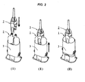
Fig. 2 is a perspective explanation view illustrating a state of locking a mixing tip with a syringe body in the dental mixer illustrated inFig. 1 . -
Fig. 3 is a brief explanation view illustrating a state of locking a mixing tip with a syringe body between two syringes of the syringe body in the dental mixer illustrated inFig. 1 . -
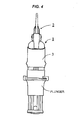
Fig. 4 is a front explanation view illustrating a state of mounting a plunger on the dental mixer illustrated inFig. 1 . - A dental mixer according to the present invention will be described in detail below with reference to the drawings.
- A
syringe body 1 includes two parallel syringes 1 a and 1 a fixed on aholder 1 b. - A
mixing tip 2 is for mixing and discharging each dental paste in the syringes 1a and 1a. The mixingtip 2 includes ahousing 2a, apaste guiding member 2b, and a pair of plate spring-shapedlocking members housing 2a has a mixing element mounted inside thereof. Thepaste guiding member 2b is provided at an end portion positioned on the side opposite to an outlet of thehousing 2a, and is for guiding a dental paste from each inside of the syringes 1 a and 1 a to the inside of thehousing 2a. The pair of plate spring-shapedlocking members paste guiding member 2b or thehousing 2a, and the lockingmembers members grooves syringe body 1. - A
sleeve 3 is slidably and externally fitted to the syringes 1 a and 1 a. Thesleeve 3 has a shape, which covers at least the pawl portions 2ca and 2ca of the lockingmembers housing 2a and thereby prevents the locking of the pawl portions 2ca and 2ca by elasticity from canceling. - Such the dental mixer according to the present invention includes, as illustrated in
Fig. 1 , thesyringe body 1 including the two parallel syringes 1 a and 1 a fixed on theholder 1b, the mixingtip 2 for mixing and discharging the dental paste in each of the syringes 1 a and 1 a, and thesleeve 3 slidably and externally fitted to the syringes 1 a and 1 a. - The
sleeve 3 is externally fitted to the syringes 1 a and 1 a (the syringe body 1) in a detachable state. However, if thesleeve 3 is previously, externally fitted to the syringes 1 a and 1 a (the syringe body 1) in an undetachable state (a fixing state or the like), thesyringe body 1 and thesleeve 3 are integrated, so that the dental mixer has an easy constitution in which only the mixingtip 2 is attached and detached. Therefore, handling becomes easy. - Further, when such the dental mixer according to the present invention is practically used, each of the pawl portions 2ca and 2ca on the tip-end side of the pair of the plate spring-shaped
locking members grooves syringe body 1, as illustrated inFig. 2 (I) andFig. 3 (I) . - Then, as illustrated in
Fig. 2 (II) andFig. 3 (II) , thesleeve 3 slides toward the outlet side of thehousing 2a so as to cover at least each of the pawl portions 2ca and 2ca of the lockingmembers sleeve 3 is in a state that locking of the pawl portions 2ca and 2ca by elasticity is prevented from canceling, as illustrated inFig. 2 (III) andFig. 3 (III) . - Further, as illustrated in
Fig. 4 , a plunger is attached to the side opposite to the outlet of thesyringe body 1 of the dental mixer according to the present invention. While keeping the state that thesleeve 3 covers at least each of the pawl portions 2ca and 2ca of the lockingmembers tip 2. - When the dental mixer is used in the above-mentioned process, mixing and using all dental pastes up in the syringes 1a and 1a are rare, and the dental paste generally remains in the syringes 1a and 1a. If the dental paste remains, the dental paste mixed in the
mixing tip 2 is hardened, so that it is difficult to reuse the dental paste later. However, each dental paste remaining in the syringes 1a and 1a are not hardened because the dental paste is not mixed. Therefore, when the dental paste remains in the syringes 1 a and 1a, the dental paste can be used later by exchanging themixing tip 2. As a result, it is very important whether the mixingtip 2 can be exchanged easily or not. - In the dental mixer according to the present invention, since the mixing
tip 2 is locked with thesyringe body 1 by using the two pawl portions 2ca and 2ca and thesleeve 3 holding the pawl portions 2ca and 2ca, the mixingtip 2 is lightly locked with thesyringe body 1 by the pawl portions 2ca and 2ca. Therefore, the mixingtip 2 can be attached and detached easily, and it does not take time and effort to exchange the mixingtip 2, so that handing is very easy. - Namely, when the dental mixer according to the present invention is used as illustrated in
Fig. 4 and reused later, thesleeve 3 holding the two pawl portions 2ca and 2ca slides toward the side opposite to the outlet of thesyringe body 1. While keeping the state of thesleeve 3, locking of the pawl portions 2ca and 2ca which are locked, by elasticity, with the pair of the lockinggrooves syringe body 1 is canceled. As a result, the mixingtip 2 can be detached easily. Then, mounting anew mixing tip 2 on thesyringe body 1 as mentioned above, all dental pastes remaining in the syringes 1 a and 1 a can be used without waste.
Claims (1)
- A dental mixer comprising:a syringe body (1) including two parallel syringes (1 a, 1 a) fixed on a holder (1 b);a mixing tip (2) for mixing and discharging a dental paste in each of the syringes (1a, 1a); anda sleeve (3) slidably and externally fitted to the syringes (1 a, 1 a),wherein the mixing tip (2) comprises:a housing (2a) having a mixing element mounted inside thereof;a paste guiding member (2b) being provided at an end portion positioned on the side opposite to an outlet of the housing (2a), and being for guiding a dental paste from each inside of the syringes (1 a, 1 a) to the inside of the housing (2a); anda pair of plate spring-shaped locking members (2c, 2c) being constituted integrally with the paste guiding member (2b) or the housing (2a), and having pawl portions (2ca, 2ca) on the tip-end side thereof, wherein the pawl portions (2ca, 2ca) are locked, by elasticity, with a pair of locking grooves (1 c, 1 c) each formed between the two syringes (1 a, 1 a) of the syringe body (1),and wherein the sleeve (3) has a shape to cover at least the pawl portions (2ca, 2ca) of the locking members (2c, 2c) when sliding toward the outlet side of the housing (2a), and thereby to prevent the locking of the pawl portions (2ca, 2ca) by elasticity from canceling.
Applications Claiming Priority (1)
| Application Number | Priority Date | Filing Date | Title |
|---|---|---|---|
| JP2013040448A JP5973365B2 (en) | 2013-03-01 | 2013-03-01 | Dental mixer |
Publications (3)
| Publication Number | Publication Date |
|---|---|
| EP2772221A2 true EP2772221A2 (en) | 2014-09-03 |
| EP2772221A3 EP2772221A3 (en) | 2015-04-22 |
| EP2772221B1 EP2772221B1 (en) | 2016-03-30 |
Family
ID=50190154
Family Applications (1)
| Application Number | Title | Priority Date | Filing Date |
|---|---|---|---|
| EP14000705.5A Active EP2772221B1 (en) | 2013-03-01 | 2014-02-27 | Dental mixer |
Country Status (4)
| Country | Link |
|---|---|
| US (1) | US9381070B2 (en) |
| EP (1) | EP2772221B1 (en) |
| JP (1) | JP5973365B2 (en) |
| KR (1) | KR102218485B1 (en) |
Families Citing this family (5)
| Publication number | Priority date | Publication date | Assignee | Title |
|---|---|---|---|---|
| US9572555B1 (en) * | 2015-09-24 | 2017-02-21 | Ethicon, Inc. | Spray or drip tips having multiple outlet channels |
| CN206080750U (en) * | 2016-07-26 | 2017-04-12 | B.J.M.实验室有限公司 | A manual hybrid connector of removable formula for double -barrelled syringe |
| CN113164236A (en) * | 2018-12-04 | 2021-07-23 | 3M创新有限公司 | Syringe for storing and dispensing materials |
| DE102019101640A1 (en) | 2019-01-23 | 2020-07-23 | 3lmed GmbH | cartridge |
| WO2025164699A1 (en) * | 2024-01-31 | 2025-08-07 | クラレノリタケデンタル株式会社 | Paste injector and method for mixing dental material |
Family Cites Families (62)
| Publication number | Priority date | Publication date | Assignee | Title |
|---|---|---|---|---|
| US2784987A (en) * | 1954-02-03 | 1957-03-12 | Corcoran Richard Stanley | Pipe coupling with detent means |
| US3604410A (en) * | 1968-09-11 | 1971-09-14 | Gary L Whitacre | Multitube blood sampler |
| US4367737A (en) * | 1981-04-06 | 1983-01-11 | George Kozam | Multiple barrel syringe |
| US4717077A (en) * | 1982-08-26 | 1988-01-05 | Ag-Chem Equipment Co., Inc. | Self-aligning coupler for fluid transmitting conduits |
| JPS6031955U (en) * | 1983-08-09 | 1985-03-04 | 大阪機工株式会社 | Automatic stylus changer |
| EP0294672B1 (en) * | 1987-06-10 | 1992-08-12 | Wilhelm A. Keller | Double cartridge for a two-component compound |
| DE3725291A1 (en) * | 1987-07-30 | 1989-02-09 | Hilti Ag | CARTRIDGE MAGAZINE FOR FLOWABLE MEASURES |
| US4974756A (en) * | 1989-07-14 | 1990-12-04 | Minnesota Mining And Manufacturing Company | Double barrel dispensing container and cap therefor |
| CH681146A5 (en) | 1990-07-20 | 1993-01-29 | Wilhelm A Keller | |
| US5240146A (en) * | 1990-12-14 | 1993-08-31 | Smedley William H | Variable proportion dispenser |
| US5301842A (en) * | 1991-03-06 | 1994-04-12 | Frank Ritter | Multicomponent cartridge for plastic materials |
| DK68991D0 (en) * | 1991-04-17 | 1991-04-17 | Novo Nordisk As | HEADER |
| US5354284A (en) * | 1992-06-09 | 1994-10-11 | Habley Medical Technology Corporation | Multiple injection syringe system |
| US5824012A (en) * | 1993-05-12 | 1998-10-20 | The Medicine Bottle Company, Inc. | Nursing bottle with medication dispenser |
| US5383906A (en) * | 1993-05-12 | 1995-01-24 | Burchett; Mark T. | Nursing bottle with medication dispenser |
| US5445614A (en) * | 1993-10-20 | 1995-08-29 | Habley Medical Technology Corporation | Pharmaceutical storage and mixing syringe |
| US5462204A (en) * | 1994-03-29 | 1995-10-31 | Rhh Foam Systems, Inc. | Foam dispensing gun |
| US5562219A (en) * | 1994-09-22 | 1996-10-08 | Valois, S.A. | Device for attaching a dispenser member to a receptacle |
| EP0723807B1 (en) | 1995-01-16 | 2001-09-19 | Wilhelm A. Keller | Mixer and multiple component dispensing device assembly and method for the aligned connection of the mixer to the multiple component dispensing device |
| US5810792A (en) * | 1996-04-03 | 1998-09-22 | Icu Medical, Inc. | Locking blunt cannula |
| DE69716887T2 (en) * | 1997-06-18 | 2003-03-20 | Wilhelm A. Keller | mixer |
| CA2247801A1 (en) * | 1997-10-15 | 1999-04-15 | Arthur Zwingenberger | Apparatus for mixing and applying a multicomponent molding mass |
| DE19745567C2 (en) * | 1997-10-15 | 2003-02-20 | Arthur Zwingenberger | Device for dispensing a viscous liquid |
| ATE232490T1 (en) * | 1999-03-23 | 2003-02-15 | Saint Gobain Calmar Sa | BOTTLE CAP |
| US6345776B1 (en) * | 1999-12-23 | 2002-02-12 | Fomo Products Inc. | Two-component dispensing gun |
| KR100791757B1 (en) * | 2001-06-27 | 2008-01-04 | 가부시키가이샤 가네보케쇼힝 | Mixed Injection Device |
| DE10159255A1 (en) * | 2001-12-03 | 2003-06-18 | Bsh Bosch Siemens Hausgeraete | Coupling part for connecting at least one tubular or rod-shaped part to another part |
| DE10233051A1 (en) * | 2002-07-19 | 2004-02-05 | Coltène/Whaledent GmbH + Co. KG | Dispensing system for fluid substances |
| US20040033466A1 (en) * | 2002-08-15 | 2004-02-19 | Kerr Corporation | Single dose dental restorative material delivery system and method |
| US6843652B2 (en) * | 2002-12-06 | 2005-01-18 | Kerr Corporation | Single dose dental impression material delivery system and method |
| DE10258953A1 (en) * | 2002-12-16 | 2004-07-22 | S&C Polymer Silicon- und Composite-Spezialitäten GmbH | Dispenser for fluid substances |
| US6834888B2 (en) * | 2003-02-04 | 2004-12-28 | Flow-Rite Controls, Ltd. | Connector |
| US20050035153A1 (en) * | 2003-08-11 | 2005-02-17 | Brown Daniel P. | Multi-component fluid dispensing device with mixing enhancement |
| US6976640B2 (en) * | 2003-12-04 | 2005-12-20 | Kuo-Liang Chen | Air gun with a quick-releasing device |
| ES2371729T3 (en) * | 2004-07-08 | 2012-01-09 | Sulzer Mixpac Ag | DISPENSATION PROVISION WITH A SYRINGE OR A CARTRIDGE, A CLOSING CAP AND A MIXING ELEMENT. |
| WO2006005213A1 (en) * | 2004-07-08 | 2006-01-19 | Mixpac Systems Ag | Disposable discharge device |
| JP2008504955A (en) * | 2004-07-08 | 2008-02-21 | メッドミックス システムズ アーゲー | Formulation system comprising an injector or cartridge and a mixer |
| DE502004010975D1 (en) * | 2004-07-16 | 2010-05-12 | Dentaco Gmbh | Multi-chamber ampoule for dispensing a mixture of several substances |
| ES2329491T3 (en) * | 2004-10-15 | 2009-11-26 | Medmix Systems Ag | STATIC MIXER. |
| FR2880001B1 (en) * | 2004-12-23 | 2011-01-21 | Valois Sas | FLUID PRODUCT DISPENSER. |
| DE202005000929U1 (en) * | 2005-01-20 | 2005-03-31 | Kettenbach Gmbh & Co Kg | Device for storing and discharging fluid substances |
| DE102005002850B4 (en) * | 2005-01-20 | 2009-09-17 | Kettenbach Gmbh & Co. Kg | Device for storing and discharging fluid substances |
| FR2886632B1 (en) * | 2005-06-03 | 2007-09-07 | Valois Sas | FIXING ASSEMBLY FOR A FLUID PRODUCT DISPENSING MEMBER |
| US7575131B2 (en) * | 2005-07-13 | 2009-08-18 | Ethicon, Inc. | Multi-component delivery system |
| ES2355478T3 (en) * | 2005-09-19 | 2011-03-28 | Valois Sas | LOCK HOSE FOR FIXING A CLOSURE DEVICE AND CLOSURE DEVICE. |
| US7717357B2 (en) * | 2006-01-09 | 2010-05-18 | Fomo Products, Inc. | Method for rapid insulation of expanses |
| DE102006047811A1 (en) * | 2006-10-06 | 2008-05-15 | Sulzer Chemtech Ag | Multicomponent cartridge |
| JP5172185B2 (en) | 2007-03-22 | 2013-03-27 | 株式会社ジーシー | Mixing chip |
| GB0707573D0 (en) * | 2007-04-19 | 2007-05-30 | 3M Innovative Properties Co | Dispensing device with locking member |
| FR2916743B1 (en) * | 2007-05-29 | 2009-08-28 | Valois Sas | FIXING DEVICE FOR ATTACHING A PUMP TO A TANK AND DISPENSER USING SUCH A FIXING DEVICE |
| JP5622148B2 (en) * | 2007-09-19 | 2014-11-12 | ケッテンバッハ ゲゼルシャフト ミット ベシュレンクテル ハフツングウント コンパニー コマンディートゲゼルシャフトKettenbachGmbH & Co. KG | Dispensing device |
| KR20100059895A (en) * | 2007-09-19 | 2010-06-04 | 케텐바흐 게엠베하 운트 콤파니 카게 | Dispensing device |
| JP5172514B2 (en) * | 2008-07-15 | 2013-03-27 | 株式会社ジーシー | Mixing chip |
| CH699398A1 (en) * | 2008-08-22 | 2010-02-26 | Medmix Systems Ag | Fitting for discharge. |
| CA2686581C (en) * | 2009-02-11 | 2017-06-27 | Sulzer Mixpac Ag | Intermediate piece for the connection of a storage container to a static mixer |
| FR2945283B1 (en) * | 2009-05-06 | 2015-06-26 | Valois Sas | FIXING DEVICE FOR ATTACHING A PUMP TO A RESERVOIR COLLAR |
| EP2485852B1 (en) * | 2009-10-06 | 2013-10-30 | Medmix Systems AG | Application assembly with a connection device between a multi-component cartridge and an accessory part |
| US8672237B2 (en) * | 2010-06-25 | 2014-03-18 | Baxter International Inc. | Device for mixing and dispensing of two-component reactive surgical sealant |
| ES2437941T3 (en) * | 2011-03-11 | 2014-01-15 | Sulzer Mixpac Ag | Multi-component cartridge |
| US8919609B2 (en) * | 2012-01-10 | 2014-12-30 | Pac-Dent International, Inc. | Dental mixing device having an auto-aligning tip mixing tip |
| WO2014063848A1 (en) * | 2012-10-23 | 2014-05-01 | Sulzer Mixpac Ag | Discharging device |
| US9138772B2 (en) * | 2012-10-31 | 2015-09-22 | Nordson Corporation | Dispensing assembly and method using snap engagement of a mixer and a cartridge |
-
2013
- 2013-03-01 JP JP2013040448A patent/JP5973365B2/en active Active
-
2014
- 2014-02-26 KR KR1020140022534A patent/KR102218485B1/en active Active
- 2014-02-27 US US14/191,865 patent/US9381070B2/en active Active
- 2014-02-27 EP EP14000705.5A patent/EP2772221B1/en active Active
Also Published As
| Publication number | Publication date |
|---|---|
| US9381070B2 (en) | 2016-07-05 |
| KR102218485B1 (en) | 2021-02-19 |
| EP2772221B1 (en) | 2016-03-30 |
| JP5973365B2 (en) | 2016-08-23 |
| EP2772221A3 (en) | 2015-04-22 |
| US20140246457A1 (en) | 2014-09-04 |
| JP2014168728A (en) | 2014-09-18 |
| KR20140109275A (en) | 2014-09-15 |
Similar Documents
| Publication | Publication Date | Title |
|---|---|---|
| EP2772221B1 (en) | Dental mixer | |
| US8007164B2 (en) | Mixing tip | |
| EP2145599A1 (en) | Mixing tip | |
| JP5087072B2 (en) | Delivery device with removable attachment | |
| JP2009527292A (en) | Supply device for double syringe | |
| JP2012500753A (en) | Connector for discharge device | |
| WO2004100771A3 (en) | Bone cement mixing and delivery system | |
| US20160199862A1 (en) | Foam gun | |
| CN106361454B (en) | Portable medicine pushing device | |
| JP4916440B2 (en) | A compounding device including a compounding device and a multi-component injector | |
| US9693838B2 (en) | Dual-barrel cartridge adaptor | |
| JP3188762U (en) | Divided storage container | |
| JP6091621B2 (en) | Impression material automatic kneading equipment | |
| CN106714979A (en) | Arrangement for pressing a pasty or fluid substance out of a film bag | |
| CN110167671B (en) | Flow distribution unit and handheld dosing device with at least one flow distribution unit | |
| TW200719977A (en) | Material dispensing apparatus | |
| JP2015047539A (en) | Paste mixer and dispenser | |
| JP2007095793A (en) | Removable structure of cover to casing | |
| CN206427757U (en) | Multi-stage distribution device | |
| JP2005214332A (en) | Fitting structure of additional member | |
| KR20190050031A (en) | Mixing tip | |
| JP4330556B2 (en) | Medical paste kneading injector | |
| KR20100104047A (en) | Camera and grip unit | |
| WO2005001521A3 (en) | Locking device for a projector component | |
| JP2016036402A (en) | Medical paste kneading injector |
Legal Events
| Date | Code | Title | Description |
|---|---|---|---|
| PUAI | Public reference made under article 153(3) epc to a published international application that has entered the european phase |
Free format text: ORIGINAL CODE: 0009012 |
|
| 17P | Request for examination filed |
Effective date: 20140227 |
|
| AK | Designated contracting states |
Kind code of ref document: A2 Designated state(s): AL AT BE BG CH CY CZ DE DK EE ES FI FR GB GR HR HU IE IS IT LI LT LU LV MC MK MT NL NO PL PT RO RS SE SI SK SM TR |
|
| AX | Request for extension of the european patent |
Extension state: BA ME |
|
| PUAL | Search report despatched |
Free format text: ORIGINAL CODE: 0009013 |
|
| AK | Designated contracting states |
Kind code of ref document: A3 Designated state(s): AL AT BE BG CH CY CZ DE DK EE ES FI FR GB GR HR HU IE IS IT LI LT LU LV MC MK MT NL NO PL PT RO RS SE SI SK SM TR |
|
| AX | Request for extension of the european patent |
Extension state: BA ME |
|
| RIC1 | Information provided on ipc code assigned before grant |
Ipc: A61C 5/06 20060101AFI20150316BHEP |
|
| R17P | Request for examination filed (corrected) |
Effective date: 20150521 |
|
| RBV | Designated contracting states (corrected) |
Designated state(s): AL AT BE BG CH CY CZ DE DK EE ES FI FR GB GR HR HU IE IS IT LI LT LU LV MC MK MT NL NO PL PT RO RS SE SI SK SM TR |
|
| GRAP | Despatch of communication of intention to grant a patent |
Free format text: ORIGINAL CODE: EPIDOSNIGR1 |
|
| INTG | Intention to grant announced |
Effective date: 20151028 |
|
| GRAS | Grant fee paid |
Free format text: ORIGINAL CODE: EPIDOSNIGR3 |
|
| RIN1 | Information on inventor provided before grant (corrected) |
Inventor name: NOGUCHI, KAZUMA Inventor name: MIYANO, TATSUNOSUKE |
|
| GRAA | (expected) grant |
Free format text: ORIGINAL CODE: 0009210 |
|
| AK | Designated contracting states |
Kind code of ref document: B1 Designated state(s): AL AT BE BG CH CY CZ DE DK EE ES FI FR GB GR HR HU IE IS IT LI LT LU LV MC MK MT NL NO PL PT RO RS SE SI SK SM TR |
|
| REG | Reference to a national code |
Ref country code: GB Ref legal event code: FG4D |
|
| REG | Reference to a national code |
Ref country code: CH Ref legal event code: EP |
|
| REG | Reference to a national code |
Ref country code: AT Ref legal event code: REF Ref document number: 784468 Country of ref document: AT Kind code of ref document: T Effective date: 20160415 |
|
| REG | Reference to a national code |
Ref country code: IE Ref legal event code: FG4D |
|
| REG | Reference to a national code |
Ref country code: DE Ref legal event code: R096 Ref document number: 602014001213 Country of ref document: DE |
|
| REG | Reference to a national code |
Ref country code: LT Ref legal event code: MG4D |
|
| PG25 | Lapsed in a contracting state [announced via postgrant information from national office to epo] |
Ref country code: FI Free format text: LAPSE BECAUSE OF FAILURE TO SUBMIT A TRANSLATION OF THE DESCRIPTION OR TO PAY THE FEE WITHIN THE PRESCRIBED TIME-LIMIT Effective date: 20160330 Ref country code: NO Free format text: LAPSE BECAUSE OF FAILURE TO SUBMIT A TRANSLATION OF THE DESCRIPTION OR TO PAY THE FEE WITHIN THE PRESCRIBED TIME-LIMIT Effective date: 20160630 Ref country code: HR Free format text: LAPSE BECAUSE OF FAILURE TO SUBMIT A TRANSLATION OF THE DESCRIPTION OR TO PAY THE FEE WITHIN THE PRESCRIBED TIME-LIMIT Effective date: 20160330 Ref country code: GR Free format text: LAPSE BECAUSE OF FAILURE TO SUBMIT A TRANSLATION OF THE DESCRIPTION OR TO PAY THE FEE WITHIN THE PRESCRIBED TIME-LIMIT Effective date: 20160701 |
|
| REG | Reference to a national code |
Ref country code: NL Ref legal event code: MP Effective date: 20160330 |
|
| REG | Reference to a national code |
Ref country code: AT Ref legal event code: MK05 Ref document number: 784468 Country of ref document: AT Kind code of ref document: T Effective date: 20160330 |
|
| PG25 | Lapsed in a contracting state [announced via postgrant information from national office to epo] |
Ref country code: RS Free format text: LAPSE BECAUSE OF FAILURE TO SUBMIT A TRANSLATION OF THE DESCRIPTION OR TO PAY THE FEE WITHIN THE PRESCRIBED TIME-LIMIT Effective date: 20160330 Ref country code: LT Free format text: LAPSE BECAUSE OF FAILURE TO SUBMIT A TRANSLATION OF THE DESCRIPTION OR TO PAY THE FEE WITHIN THE PRESCRIBED TIME-LIMIT Effective date: 20160330 Ref country code: LV Free format text: LAPSE BECAUSE OF FAILURE TO SUBMIT A TRANSLATION OF THE DESCRIPTION OR TO PAY THE FEE WITHIN THE PRESCRIBED TIME-LIMIT Effective date: 20160330 Ref country code: SE Free format text: LAPSE BECAUSE OF FAILURE TO SUBMIT A TRANSLATION OF THE DESCRIPTION OR TO PAY THE FEE WITHIN THE PRESCRIBED TIME-LIMIT Effective date: 20160330 |
|
| PG25 | Lapsed in a contracting state [announced via postgrant information from national office to epo] |
Ref country code: NL Free format text: LAPSE BECAUSE OF FAILURE TO SUBMIT A TRANSLATION OF THE DESCRIPTION OR TO PAY THE FEE WITHIN THE PRESCRIBED TIME-LIMIT Effective date: 20160330 |
|
| PG25 | Lapsed in a contracting state [announced via postgrant information from national office to epo] |
Ref country code: PL Free format text: LAPSE BECAUSE OF FAILURE TO SUBMIT A TRANSLATION OF THE DESCRIPTION OR TO PAY THE FEE WITHIN THE PRESCRIBED TIME-LIMIT Effective date: 20160330 Ref country code: IS Free format text: LAPSE BECAUSE OF FAILURE TO SUBMIT A TRANSLATION OF THE DESCRIPTION OR TO PAY THE FEE WITHIN THE PRESCRIBED TIME-LIMIT Effective date: 20160730 Ref country code: EE Free format text: LAPSE BECAUSE OF FAILURE TO SUBMIT A TRANSLATION OF THE DESCRIPTION OR TO PAY THE FEE WITHIN THE PRESCRIBED TIME-LIMIT Effective date: 20160330 |
|
| REG | Reference to a national code |
Ref country code: DE Ref legal event code: R079 Ref document number: 602014001213 Country of ref document: DE Free format text: PREVIOUS MAIN CLASS: A61C0005060000 Ipc: A61C0005600000 |
|
| PG25 | Lapsed in a contracting state [announced via postgrant information from national office to epo] |
Ref country code: SM Free format text: LAPSE BECAUSE OF FAILURE TO SUBMIT A TRANSLATION OF THE DESCRIPTION OR TO PAY THE FEE WITHIN THE PRESCRIBED TIME-LIMIT Effective date: 20160330 Ref country code: ES Free format text: LAPSE BECAUSE OF FAILURE TO SUBMIT A TRANSLATION OF THE DESCRIPTION OR TO PAY THE FEE WITHIN THE PRESCRIBED TIME-LIMIT Effective date: 20160330 Ref country code: RO Free format text: LAPSE BECAUSE OF FAILURE TO SUBMIT A TRANSLATION OF THE DESCRIPTION OR TO PAY THE FEE WITHIN THE PRESCRIBED TIME-LIMIT Effective date: 20160330 Ref country code: CZ Free format text: LAPSE BECAUSE OF FAILURE TO SUBMIT A TRANSLATION OF THE DESCRIPTION OR TO PAY THE FEE WITHIN THE PRESCRIBED TIME-LIMIT Effective date: 20160330 Ref country code: SK Free format text: LAPSE BECAUSE OF FAILURE TO SUBMIT A TRANSLATION OF THE DESCRIPTION OR TO PAY THE FEE WITHIN THE PRESCRIBED TIME-LIMIT Effective date: 20160330 Ref country code: PT Free format text: LAPSE BECAUSE OF FAILURE TO SUBMIT A TRANSLATION OF THE DESCRIPTION OR TO PAY THE FEE WITHIN THE PRESCRIBED TIME-LIMIT Effective date: 20160801 Ref country code: AT Free format text: LAPSE BECAUSE OF FAILURE TO SUBMIT A TRANSLATION OF THE DESCRIPTION OR TO PAY THE FEE WITHIN THE PRESCRIBED TIME-LIMIT Effective date: 20160330 |
|
| PG25 | Lapsed in a contracting state [announced via postgrant information from national office to epo] |
Ref country code: IT Free format text: LAPSE BECAUSE OF FAILURE TO SUBMIT A TRANSLATION OF THE DESCRIPTION OR TO PAY THE FEE WITHIN THE PRESCRIBED TIME-LIMIT Effective date: 20160330 |
|
| REG | Reference to a national code |
Ref country code: DE Ref legal event code: R097 Ref document number: 602014001213 Country of ref document: DE |
|
| REG | Reference to a national code |
Ref country code: FR Ref legal event code: PLFP Year of fee payment: 4 |
|
| PG25 | Lapsed in a contracting state [announced via postgrant information from national office to epo] |
Ref country code: DK Free format text: LAPSE BECAUSE OF FAILURE TO SUBMIT A TRANSLATION OF THE DESCRIPTION OR TO PAY THE FEE WITHIN THE PRESCRIBED TIME-LIMIT Effective date: 20160330 |
|
| PLBE | No opposition filed within time limit |
Free format text: ORIGINAL CODE: 0009261 |
|
| STAA | Information on the status of an ep patent application or granted ep patent |
Free format text: STATUS: NO OPPOSITION FILED WITHIN TIME LIMIT |
|
| 26N | No opposition filed |
Effective date: 20170103 |
|
| PG25 | Lapsed in a contracting state [announced via postgrant information from national office to epo] |
Ref country code: SI Free format text: LAPSE BECAUSE OF FAILURE TO SUBMIT A TRANSLATION OF THE DESCRIPTION OR TO PAY THE FEE WITHIN THE PRESCRIBED TIME-LIMIT Effective date: 20160330 |
|
| PG25 | Lapsed in a contracting state [announced via postgrant information from national office to epo] |
Ref country code: MC Free format text: LAPSE BECAUSE OF FAILURE TO SUBMIT A TRANSLATION OF THE DESCRIPTION OR TO PAY THE FEE WITHIN THE PRESCRIBED TIME-LIMIT Effective date: 20160330 |
|
| REG | Reference to a national code |
Ref country code: CH Ref legal event code: PL |
|
| PG25 | Lapsed in a contracting state [announced via postgrant information from national office to epo] |
Ref country code: LI Free format text: LAPSE BECAUSE OF NON-PAYMENT OF DUE FEES Effective date: 20170228 Ref country code: CH Free format text: LAPSE BECAUSE OF NON-PAYMENT OF DUE FEES Effective date: 20170228 |
|
| REG | Reference to a national code |
Ref country code: IE Ref legal event code: MM4A |
|
| PG25 | Lapsed in a contracting state [announced via postgrant information from national office to epo] |
Ref country code: LU Free format text: LAPSE BECAUSE OF NON-PAYMENT OF DUE FEES Effective date: 20170227 |
|
| REG | Reference to a national code |
Ref country code: FR Ref legal event code: PLFP Year of fee payment: 5 |
|
| PG25 | Lapsed in a contracting state [announced via postgrant information from national office to epo] |
Ref country code: IE Free format text: LAPSE BECAUSE OF NON-PAYMENT OF DUE FEES Effective date: 20170227 |
|
| PG25 | Lapsed in a contracting state [announced via postgrant information from national office to epo] |
Ref country code: MT Free format text: LAPSE BECAUSE OF NON-PAYMENT OF DUE FEES Effective date: 20170227 |
|
| GBPC | Gb: european patent ceased through non-payment of renewal fee |
Effective date: 20180227 |
|
| PG25 | Lapsed in a contracting state [announced via postgrant information from national office to epo] |
Ref country code: AL Free format text: LAPSE BECAUSE OF FAILURE TO SUBMIT A TRANSLATION OF THE DESCRIPTION OR TO PAY THE FEE WITHIN THE PRESCRIBED TIME-LIMIT Effective date: 20160330 |
|
| PG25 | Lapsed in a contracting state [announced via postgrant information from national office to epo] |
Ref country code: GB Free format text: LAPSE BECAUSE OF NON-PAYMENT OF DUE FEES Effective date: 20180227 |
|
| PG25 | Lapsed in a contracting state [announced via postgrant information from national office to epo] |
Ref country code: HU Free format text: LAPSE BECAUSE OF FAILURE TO SUBMIT A TRANSLATION OF THE DESCRIPTION OR TO PAY THE FEE WITHIN THE PRESCRIBED TIME-LIMIT; INVALID AB INITIO Effective date: 20140227 |
|
| PG25 | Lapsed in a contracting state [announced via postgrant information from national office to epo] |
Ref country code: BG Free format text: LAPSE BECAUSE OF FAILURE TO SUBMIT A TRANSLATION OF THE DESCRIPTION OR TO PAY THE FEE WITHIN THE PRESCRIBED TIME-LIMIT Effective date: 20160330 |
|
| PG25 | Lapsed in a contracting state [announced via postgrant information from national office to epo] |
Ref country code: CY Free format text: LAPSE BECAUSE OF NON-PAYMENT OF DUE FEES Effective date: 20160330 |
|
| PG25 | Lapsed in a contracting state [announced via postgrant information from national office to epo] |
Ref country code: MK Free format text: LAPSE BECAUSE OF FAILURE TO SUBMIT A TRANSLATION OF THE DESCRIPTION OR TO PAY THE FEE WITHIN THE PRESCRIBED TIME-LIMIT Effective date: 20160330 |
|
| PG25 | Lapsed in a contracting state [announced via postgrant information from national office to epo] |
Ref country code: TR Free format text: LAPSE BECAUSE OF FAILURE TO SUBMIT A TRANSLATION OF THE DESCRIPTION OR TO PAY THE FEE WITHIN THE PRESCRIBED TIME-LIMIT Effective date: 20160330 |
|
| P01 | Opt-out of the competence of the unified patent court (upc) registered |
Effective date: 20230502 |
|
| PGFP | Annual fee paid to national office [announced via postgrant information from national office to epo] |
Ref country code: DE Payment date: 20260225 Year of fee payment: 13 |
|
| PGFP | Annual fee paid to national office [announced via postgrant information from national office to epo] |
Ref country code: BE Payment date: 20260218 Year of fee payment: 13 |
|
| PGFP | Annual fee paid to national office [announced via postgrant information from national office to epo] |
Ref country code: FR Payment date: 20260225 Year of fee payment: 13 |