EP2771594B1 - Piston assembly including a polymer coating with hard particles applied to sliding surfaces - Google Patents
Piston assembly including a polymer coating with hard particles applied to sliding surfaces Download PDFInfo
- Publication number
- EP2771594B1 EP2771594B1 EP12784831.5A EP12784831A EP2771594B1 EP 2771594 B1 EP2771594 B1 EP 2771594B1 EP 12784831 A EP12784831 A EP 12784831A EP 2771594 B1 EP2771594 B1 EP 2771594B1
- Authority
- EP
- European Patent Office
- Prior art keywords
- coating
- metal
- piston
- hard particles
- sliding surface
- Prior art date
- Legal status (The legal status is an assumption and is not a legal conclusion. Google has not performed a legal analysis and makes no representation as to the accuracy of the status listed.)
- Not-in-force
Links
- 238000000576 coating method Methods 0.000 title claims description 80
- 239000011248 coating agent Substances 0.000 title claims description 75
- 239000002245 particle Substances 0.000 title claims description 50
- 229920000642 polymer Polymers 0.000 title claims description 27
- 229910052751 metal Inorganic materials 0.000 claims description 41
- 239000002184 metal Substances 0.000 claims description 41
- 210000000707 wrist Anatomy 0.000 claims description 30
- 239000011159 matrix material Substances 0.000 claims description 28
- 238000000034 method Methods 0.000 claims description 12
- 230000015572 biosynthetic process Effects 0.000 claims description 10
- 239000000314 lubricant Substances 0.000 claims description 7
- 239000007787 solid Substances 0.000 claims description 7
- 239000004696 Poly ether ether ketone Substances 0.000 claims description 6
- 239000004693 Polybenzimidazole Substances 0.000 claims description 6
- 239000004642 Polyimide Substances 0.000 claims description 6
- 229920002480 polybenzimidazole Polymers 0.000 claims description 6
- 229920002530 polyetherether ketone Polymers 0.000 claims description 6
- 229920001721 polyimide Polymers 0.000 claims description 6
- JEIPFZHSYJVQDO-UHFFFAOYSA-N iron(III) oxide Inorganic materials O=[Fe]O[Fe]=O JEIPFZHSYJVQDO-UHFFFAOYSA-N 0.000 claims description 5
- 239000000843 powder Substances 0.000 claims description 5
- 229910052737 gold Inorganic materials 0.000 claims description 4
- 229910000765 intermetallic Inorganic materials 0.000 claims description 4
- 229910052745 lead Inorganic materials 0.000 claims description 4
- 229910044991 metal oxide Inorganic materials 0.000 claims description 4
- 150000004706 metal oxides Chemical class 0.000 claims description 4
- 150000004767 nitrides Chemical class 0.000 claims description 4
- 229920002312 polyamide-imide Polymers 0.000 claims description 4
- 239000011347 resin Substances 0.000 claims description 4
- 229920005989 resin Polymers 0.000 claims description 4
- 229910021332 silicide Inorganic materials 0.000 claims description 4
- 229910052709 silver Inorganic materials 0.000 claims description 4
- 229910052582 BN Inorganic materials 0.000 claims description 3
- PZNSFCLAULLKQX-UHFFFAOYSA-N Boron nitride Chemical compound N#B PZNSFCLAULLKQX-UHFFFAOYSA-N 0.000 claims description 3
- 229920012266 Poly(ether sulfone) PES Polymers 0.000 claims description 3
- 229910052976 metal sulfide Inorganic materials 0.000 claims description 3
- 229920001230 polyarylate Polymers 0.000 claims description 3
- 239000004810 polytetrafluoroethylene Substances 0.000 claims description 3
- 229920001343 polytetrafluoroethylene Polymers 0.000 claims description 3
- 229920002050 silicone resin Polymers 0.000 claims description 3
- 230000001680 brushing effect Effects 0.000 claims description 2
- 238000007598 dipping method Methods 0.000 claims description 2
- 238000002844 melting Methods 0.000 claims description 2
- 230000008018 melting Effects 0.000 claims description 2
- 238000007639 printing Methods 0.000 claims description 2
- 238000007650 screen-printing Methods 0.000 claims description 2
- 238000005507 spraying Methods 0.000 claims description 2
- FVBUAEGBCNSCDD-UHFFFAOYSA-N silicide(4-) Chemical compound [Si-4] FVBUAEGBCNSCDD-UHFFFAOYSA-N 0.000 claims 3
- 239000007769 metal material Substances 0.000 claims 1
- 229910000831 Steel Inorganic materials 0.000 description 6
- 238000002485 combustion reaction Methods 0.000 description 6
- 239000000463 material Substances 0.000 description 6
- 239000010959 steel Substances 0.000 description 6
- 238000010276 construction Methods 0.000 description 5
- 239000000203 mixture Substances 0.000 description 4
- 229910052782 aluminium Inorganic materials 0.000 description 3
- XAGFODPZIPBFFR-UHFFFAOYSA-N aluminium Chemical compound [Al] XAGFODPZIPBFFR-UHFFFAOYSA-N 0.000 description 3
- 238000012360 testing method Methods 0.000 description 3
- VYPSYNLAJGMNEJ-UHFFFAOYSA-N Silicium dioxide Chemical compound O=[Si]=O VYPSYNLAJGMNEJ-UHFFFAOYSA-N 0.000 description 2
- GWEVSGVZZGPLCZ-UHFFFAOYSA-N Titan oxide Chemical compound O=[Ti]=O GWEVSGVZZGPLCZ-UHFFFAOYSA-N 0.000 description 2
- 230000000712 assembly Effects 0.000 description 2
- 238000000429 assembly Methods 0.000 description 2
- 229910052799 carbon Inorganic materials 0.000 description 2
- 238000004519 manufacturing process Methods 0.000 description 2
- 150000002739 metals Chemical class 0.000 description 2
- -1 such as cubic BN Chemical class 0.000 description 2
- OKTJSMMVPCPJKN-UHFFFAOYSA-N Carbon Chemical compound [C] OKTJSMMVPCPJKN-UHFFFAOYSA-N 0.000 description 1
- 229910020968 MoSi2 Inorganic materials 0.000 description 1
- 229910052581 Si3N4 Inorganic materials 0.000 description 1
- 239000007767 bonding agent Substances 0.000 description 1
- 229910052681 coesite Inorganic materials 0.000 description 1
- 229910052906 cristobalite Inorganic materials 0.000 description 1
- 229920006037 cross link polymer Polymers 0.000 description 1
- 238000009826 distribution Methods 0.000 description 1
- 229910002804 graphite Inorganic materials 0.000 description 1
- 239000010439 graphite Substances 0.000 description 1
- 238000005304 joining Methods 0.000 description 1
- 239000007788 liquid Substances 0.000 description 1
- 150000001247 metal acetylides Chemical class 0.000 description 1
- 238000012986 modification Methods 0.000 description 1
- 230000004048 modification Effects 0.000 description 1
- 229910052961 molybdenite Inorganic materials 0.000 description 1
- CWQXQMHSOZUFJS-UHFFFAOYSA-N molybdenum disulfide Chemical compound S=[Mo]=S CWQXQMHSOZUFJS-UHFFFAOYSA-N 0.000 description 1
- 229910052982 molybdenum disulfide Inorganic materials 0.000 description 1
- 239000004033 plastic Substances 0.000 description 1
- 229920003023 plastic Polymers 0.000 description 1
- 229920001296 polysiloxane Polymers 0.000 description 1
- 230000005855 radiation Effects 0.000 description 1
- 239000000377 silicon dioxide Substances 0.000 description 1
- 229910052682 stishovite Inorganic materials 0.000 description 1
- 239000000126 substance Substances 0.000 description 1
- 229920001059 synthetic polymer Polymers 0.000 description 1
- 229920001169 thermoplastic Polymers 0.000 description 1
- 229920001187 thermosetting polymer Polymers 0.000 description 1
- 239000004416 thermosoftening plastic Substances 0.000 description 1
- 229910052905 tridymite Inorganic materials 0.000 description 1
- ITRNXVSDJBHYNJ-UHFFFAOYSA-N tungsten disulfide Chemical compound S=[W]=S ITRNXVSDJBHYNJ-UHFFFAOYSA-N 0.000 description 1
- 229920006337 unsaturated polyester resin Polymers 0.000 description 1
Images


Classifications
-
- F—MECHANICAL ENGINEERING; LIGHTING; HEATING; WEAPONS; BLASTING
- F16—ENGINEERING ELEMENTS AND UNITS; GENERAL MEASURES FOR PRODUCING AND MAINTAINING EFFECTIVE FUNCTIONING OF MACHINES OR INSTALLATIONS; THERMAL INSULATION IN GENERAL
- F16J—PISTONS; CYLINDERS; SEALINGS
- F16J1/00—Pistons; Trunk pistons; Plungers
- F16J1/10—Connection to driving members
- F16J1/14—Connection to driving members with connecting-rods, i.e. pivotal connections
- F16J1/16—Connection to driving members with connecting-rods, i.e. pivotal connections with gudgeon-pin; Gudgeon-pins
-
- F—MECHANICAL ENGINEERING; LIGHTING; HEATING; WEAPONS; BLASTING
- F02—COMBUSTION ENGINES; HOT-GAS OR COMBUSTION-PRODUCT ENGINE PLANTS
- F02F—CYLINDERS, PISTONS OR CASINGS, FOR COMBUSTION ENGINES; ARRANGEMENTS OF SEALINGS IN COMBUSTION ENGINES
- F02F3/00—Pistons
- F02F3/0015—Multi-part pistons
-
- F—MECHANICAL ENGINEERING; LIGHTING; HEATING; WEAPONS; BLASTING
- F02—COMBUSTION ENGINES; HOT-GAS OR COMBUSTION-PRODUCT ENGINE PLANTS
- F02F—CYLINDERS, PISTONS OR CASINGS, FOR COMBUSTION ENGINES; ARRANGEMENTS OF SEALINGS IN COMBUSTION ENGINES
- F02F3/00—Pistons
- F02F3/10—Pistons having surface coverings
Definitions
- This invention relates generally to piston assemblies for internal combustion engine applications, and methods of forming the same.
- Piston assemblies for use in internal combustion engine applications typically comprise a piston body including a cross bore, a connecting rod also including a cross bore aligned with the cross bore of the piston body, and a wrist pin disposed in the aligned bores to couple the piston body to the connecting rod.
- bushings have been pressed between the cross bores and wrist pin to reduce friction and wear along the sliding surfaces of those components.
- bushings have been replaced by low-friction coatings, for example the coatings disclosed in U.S. Patent Nos. 7,024,981 and 6,557,457 , both assigned to Federal-Mogul World Wide, Inc.
- WO 2004/070238 A2 relates to a piston which has a coating applied to one of its sliding surfaces.
- DE 10 2008 055 194 A1 is further prior art.
- One aspect of the invention provides a piston assembly for an internal combustion engine comprising a piston body and a wrist pin.
- the piston body includes at least one first cross bore presenting a piston sliding surface.
- the wrist pin is disposed in the first cross bores and presents a pin sliding surface facing the piston sliding surfaces.
- a coating is disposed on at least one of the sliding surfaces.
- the coating includes a polymer matrix with hard particles disposed in the matrix.
- Another aspect of the invention provides a method of forming a piston assembly.
- the method includes providing a piston body including at least one first cross bore presenting a piston sliding surface and providing a wrist pin presenting a pin sliding surface.
- the method further includes disposing a coating including a polymer matrix with hard particles in the matrix on at least one of the sliding surfaces.
- the coating of the piston assembly lubricates the interface between the sliding surfaces and separates asperities of the sliding surfaces moving and rubbing against one another during use of the piston assembly in an internal combustion engine application.
- the coating reduces wear, scuff, heat, and stress on the sliding surfaces caused by friction between the sliding surfaces during operation.
- Test results suggest the coating of the present invention provides for reduced wear on the sliding surfaces, compared to other coatings and uncoated sliding surfaces.
- a piston assembly 20 constructed according to one embodiment of the invention is generally shown in Figure 1 .
- the piston assembly 20 comprises a piston body 22 having an upper crown portion 24 and a pin boss formation 28.
- the piston body 22 is preferably formed of a steel material and is either cast or forged. However, the piston body 22 can be formed of other metals, such as aluminum.
- the upper crown portion 24 is formed with ring grooves 26 for maintaining rings (not shown).
- the piston body 22 further includes the pin boss formation 28 depending from and integral with the upper crown portion 24.
- the pin boss formation 28 includes a first cross bore 30 presenting a piston sliding surface 32.
- the piston sliding surface 32 extends circumferentially around a center axis and can present oil grooves or clip grooves.
- the piston body 22 also includes a skirt 34 extending longitudinally from the upper crown portion 24.
- the skirt 34 is formed separate from the upper crown portion 24.
- the skirt 34 also includes a pair of first cross bores 30 each presenting a piston sliding surface 32.
- the first cross bore 30 of the pin boss formation 28 is disposed between the pair of first cross bores 30 of the skirt 34 , as shown in Figure 1 .
- the first cross bores 30 of the skirt 34 are axially aligned with the first cross bore 30 of the pin boss formation 28.
- the skirt 34 can be formed from a material different from the steel material of the upper crown portion 24 , such as aluminum. Alternatively, the skirt 34 and separate upper crown portion 24 can both be formed of steel.
- the piston assembly 20 includes a wrist pin 36 joining the skirt 34 to the upper crown portion 24 .
- the wrist pin 36 extends through the first cross bores 30 to provide an articulated structure.
- the piston body 22 includes the skirt 34 formed integral with the upper crown portion 24 in a single piece construction.
- the skirt 34 of the single piece construction includes a pair of the axially aligned first cross bores 30 facing opposite one another and each having the piston sliding surface 32.
- the single construction can also be formed of various materials, such as steel, aluminum, or other metals.
- the piston assembly 20 includes a fixed wrist pin 36 (not shown), wherein the wrist pin 36 is fixed to the first cross bores 30 via and interference fit.
- the piston assembly 20 also includes a connecting rod 38 for connecting the piston body 22 to a crankshaft (not shown) of the internal combustion engine.
- the connecting rod 38 includes a shaft 40 having a small end formed with a second cross bore 42 for aligning with the first cross bores 30 of the pin boss formation 28 and skirt 34.
- the second cross bore 42 presents a rod sliding surface 44.
- the connecting rod 38 is preferably formed of steel or another metal and is either cast or forged.
- the piston assembly 20 is formed by aligning the first cross bores 30 of the piston body 22 with the second cross bore 42 of the connecting rod 38 , and then disposing the wrist pin 36 in the aligned cross bores 30, 42 .
- the wrist pin 36 connects the connecting rod 38 to the piston body 22.
- the piston body 22 comprises the single piece construction
- the wrist pin 36 connects the single piece construction to the connecting rod 38.
- the wrist pin 36 also has a pin sliding surface 46 facing outwardly toward the piston sliding surface 32 and the rod sliding surface 44.
- the wrist pin 36 is also preferably formed of steel or another metal.
- the piston assembly 20 can comprise other configurations with sliding surfaces or can be formed of other materials.
- a coating 48 including a polymer matrix 50 with hard particles 52 disposed throughout the polymer matrix 50 is then disposed on at least one of the sliding surfaces 32, 44, 46, and preferably at least the piston sliding surface 32.
- the coating 48 may extend 360° along at least one of the sliding surfaces 32, 44, 46, thus encompassing the entire sliding surface 32, 44, 46.
- the coating 48 may extend less than 360° along at least one of the sliding surfaces 32, 44, 46, such as a fraction of at least one of the sliding surfaces 32, 44, 46.
- the coating 48 is disposed continuously along the piston sliding surfaces 32 of the first cross bores 30.
- the embodiment of Figure 4 also includes the coating 48 disposed continuously along the piston sliding surfaces 32 of the aligned first cross bores 30.
- the coating 48 is disposed on the pin sliding surface 46 of the wrist pin 36 and/or the rod sliding surface 44 of the connecting rod 38.
- the coating 48 can alternatively be disposed on all of the sliding surfaces 32, 44, 46 or on any combination of the sliding surfaces 32, 44, 46.
- the coating 48 has a thickness of 4 to 20 microns.
- the coating 48 comprises the polymer matrix 50 and the plurality of hard particles 52 dispersed throughout the polymer matrix 50. Examples of the coating 48 are disclosed in International Publication No. WO 2010/076306 and U.S. Patent Application Serial No. 13/142,887 . In one embodiment the coating 48 includes, in volume percent (vol. %) of the coating 48, the polymer matrix 50 in an amount of at least 40.0 vol. %, or at least 50 vol. %, or at least 60 vol. %, or at least 80 vol. %, or at least 85 vol. %, based on the total volume of the coating 48.
- the polymer matrix 50 can be formed of a single polymer or a mixture of polymers, resin, plastics, or duroplastics, and either thermoplastic or thermoset polymers.
- the polymer matrix 50 can also include synthetic and cross-linked polymers.
- the polymer matrix 50 has a high temperature resistance and excellent chemical resistance.
- the polymer matrix 50 typically has a melting point of at least 210° C, preferably at least 220° C, or at least 230° C, or at least 250° C.
- the polymer matrix 50 includes at least one of polyarylate, polyetheretherketone (PEEK), polyethersulfone (PES), polyamide imide (PAI), polyimide (PI), expoxy resin, polybenzimidazole (PBI), and silicone resin.
- the polymer matrix 50 includes a bonding agent, such as an unsaturated polyester resin or silicone, hardened by means of UV radiation.
- the hard particles 52 of the coating 48 are typically formed of a material having a hardness of at least 600 HV/0.5, more preferably at least 620 HV/0.5, and even more preferably at least 650 HV/0.5, at a temperature of 25° C.
- the hard particles 52 also have a particle size sufficient to affect at least one of the ductility, wear resistance, and strength of the coating 48.
- the hard particles 52 have a D50 particle size by volume not greater than 10.0 microns, or not greater than 8.0 microns, or not greater than 6.0 microns, and preferably from 0.1 to 5.0 microns.
- the D50 particle size by volume is the equivalent spherical diameter of the hard particles 52, also referred to as a D50 diameter, wherein 50.0 wt. % of the hard particles 52 have a larger equivalent spherical diameter and 50.0 wt. % of the hard particles 52 have a smaller equivalent spherical diameter.
- the D50 diameter is determined from a particle size distribution display of the hard particles 52, before any processing of the hard particles 52 following common testing practice.
- the hard particles 52 include a mixture of particle sizes, such as a first group of particles having a smaller particle size than a second group of particles. The first and second groups of the hard particles 52 are typically dispersed evenly throughout the polymer matrix 50.
- the hard particles 52 of the coating 48 include at least one of metal nitrides, such as such as cubic BN, and Si 3 N 4 ; metal carbides, such as SiC and B 4 C; metal oxides, such as TiO 2 , Fe 2 O 3 , and SiO 2 ; metal silicides, such as MoSi 2 ; metal borides; metal phosphides, such as Fe 3 P; intermetallic compounds; metal oxynitrides; metal carbonitrides; metal oxycarbides; metal powders of Ag, Pb, Au, SnBi and/or Cu; and mixtures thereof.
- the coating 48 typically includes the hard particles 52 in an amount of 0.1 to 20.0 vol. %, or 3.0 to 8.0 vol.
- the coating 48 includes Fe 2 O 3 as one of the hard particles 52 in an amount of 0.1 to 15.0 vol. %, or 0.5 to 8.0 vol. %, based on the total volume of the coating 28, and other hard particles 48 in an amount up to 5.0 vol. %, or 3.0 to 5.0 vol. %, based on the total volume of the coating 48.
- the coating 48 also typically includes at least one solid lubricant, such as MoS 2 , graphite, WS 2 . hexagonal boron nitride (h-BN), and PTFE.
- the solid lubricant can also include metal sulfides with layered structures.
- the coating 48 includes, in vol. % of the coating 48, the solid lubricant in an amount of 5.0 to 40.0 vol. %, or 5.0 to 30.0 vol. %, or up to 30.0 vol. %, or up to 9.5 vol. %, based on the total volume of the coating 48.
- the coating 48 is applied to at least one of the sliding surfaces 32, 44, 46, of the respective piston body 22, skirt 34, connecting rod 38, or wrist pin 36 presenting the sliding surface 32, 44, 46.
- the coating 48 can be applied as a liquid or a powder, and is typically applied according to methods disclosed in US 2010/076306 , or other methods.
- the coating 48 can be applied to the sliding surfaces 32, 44, 46 by dipping, brushing, atomizing, spraying, printing, or screen printing.
- the coating 48 may be applied 360° along at least one of the sliding surfaces 32, 44, 46, thus encompassing the entire sliding surface 32, 44, 46.
- the coating 48 may be applied less than 360° along at least one of the sliding surfaces 32, 44, 46, such as a fraction of the sliding surface 32, 44, 46.
- the coating 48 is applied directly to the piston sliding surface 32 without another layer between the piston sliding surface 32 and the coating 48.
- the method can include applying the coating 48 to the piston sliding surfaces 32 and/or the pin sliding surface 46 prior to fixing the wrist pin 36 to the piston sliding surfaces 32.
- the wrist pin 36 can also be heated prior to sliding the wrist pin 36 along the piston sliding surfaces 32 and through the first cross bores 30.
- multiple layers of the coating 48 are applied to at least one of the sliding surfaces 32, 44, 46.
- the compositions of the layers can be the same or different from one another.
- a primer can be applied to the piston sliding surface 32 before the coating 48 is applied.
- a layer of the polymer matrix 50, without the hard particles 52 is applied to the piston sliding surface 32 prior to applying the coating 48 with hard particles 52, or after applying the coating 48 with hard particles 52.
- several layers of the coating 48 are applied to the piston sliding surface 32 as a gradient, with the layer properties continuously changing along the thickness of the coating 48.
- the amount of hard particles 52 can be higher in a base layer than in a top layer, or higher in a top layer than in a base layer.
- the coating 48 comprises a plurality of layers, wherein the amount of Fe 2 O 3 in the bottom layer is higher than the amount of Fe 2 O 3 in the top layer.
- the coating 48 of the piston assembly 20 lubricates the interface between the sliding surfaces 32, 44, 46 and separates asperities of the sliding surfaces 32, 44, 46 moving and rubbing against one another during use of the piston assembly 20 in an internal combustion engine application.
- the hard particles 52 in the polymer matrix 50 may lap or cover asperities of the adjacent sliding surfaces 32, 44, 46, thus affecting bearing ratio and reducing friction.
- the hard particles 52 may also lower localized pressure by increasing the surface area of the sliding surfaces 32, 44, 46.
- the coating 48 reduces wear, scuff, heat, and stress on the sliding surfaces 32, 44, 46 caused by friction between the sliding surfaces 32, 44, 46 during operation.
- the coatings 48 of the present invention provide for reduced wear on the sliding surfaces 32, 44, 46, compared to other coatings and uncoated metal sliding surfaces.
- Other advantages are provided by the piston assembly 20 with the fixed wrist pin 36.
- the coating 48 improves the fit of the wrist pin 36 in the first cross bores 30, improves tribology, and reduces noise during operation of the piston assembly 20.
- the coating 48 also compensates for imperfections and asperity variation along the piston sliding surface 32, and thus reduces manufacturing costs.
Landscapes
- Engineering & Computer Science (AREA)
- General Engineering & Computer Science (AREA)
- Chemical & Material Sciences (AREA)
- Combustion & Propulsion (AREA)
- Mechanical Engineering (AREA)
- Pistons, Piston Rings, And Cylinders (AREA)
Description
- This invention relates generally to piston assemblies for internal combustion engine applications, and methods of forming the same.
- Piston assemblies for use in internal combustion engine applications typically comprise a piston body including a cross bore, a connecting rod also including a cross bore aligned with the cross bore of the piston body, and a wrist pin disposed in the aligned bores to couple the piston body to the connecting rod. In the past, bushings have been pressed between the cross bores and wrist pin to reduce friction and wear along the sliding surfaces of those components. Recently, in effort to reduce manufacturing complexity and costs, bushings have been replaced by low-friction coatings, for example the coatings disclosed in
U.S. Patent Nos. 7,024,981 and6,557,457 , both assigned to Federal-Mogul World Wide, Inc. -
WO 2004/070238 A2 relates to a piston which has a coating applied to one of its sliding surfaces.DE 10 2008 055 194 A1 is further prior art. - The invention is defined by the independent claims
- One aspect of the invention provides a piston assembly for an internal combustion engine comprising a piston body and a wrist pin. The piston body includes at least one first cross bore presenting a piston sliding surface. The wrist pin is disposed in the first cross bores and presents a pin sliding surface facing the piston sliding surfaces. A coating is disposed on at least one of the sliding surfaces. The coating includes a polymer matrix with hard particles disposed in the matrix.
- Another aspect of the invention provides a method of forming a piston assembly. The method includes providing a piston body including at least one first cross bore presenting a piston sliding surface and providing a wrist pin presenting a pin sliding surface. The method further includes disposing a coating including a polymer matrix with hard particles in the matrix on at least one of the sliding surfaces.
- The coating of the piston assembly lubricates the interface between the sliding surfaces and separates asperities of the sliding surfaces moving and rubbing against one another during use of the piston assembly in an internal combustion engine application. Thus, the coating reduces wear, scuff, heat, and stress on the sliding surfaces caused by friction between the sliding surfaces during operation. Test results suggest the coating of the present invention provides for reduced wear on the sliding surfaces, compared to other coatings and uncoated sliding surfaces.
- Other advantages of the present invention will be readily appreciated, as the same becomes better understood by reference to the following detailed description when considered in connection with the accompanying drawings wherein:
-
Figure 1 is a perspective and partial cross-sectional view of a piston body, connecting rod, and a wrist pin according to one embodiment of the invention; -
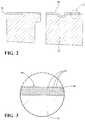
Figure 2 is a cross-sectional view of a coating disposed on the piston body ofFigure 1 ; -
Figure 3 is an enlarged cross-sectional view of the coating ofFigure 2 ; and -
Figure 4 is a perspective and partial cross-sectional view of a piston body and a wrist pin according to another embodiment of the invention. - A
piston assembly 20 constructed according to one embodiment of the invention is generally shown inFigure 1 . Thepiston assembly 20 comprises apiston body 22 having anupper crown portion 24 and apin boss formation 28. Thepiston body 22 is preferably formed of a steel material and is either cast or forged. However, thepiston body 22 can be formed of other metals, such as aluminum. Theupper crown portion 24 is formed withring grooves 26 for maintaining rings (not shown). Thepiston body 22 further includes thepin boss formation 28 depending from and integral with theupper crown portion 24. Thepin boss formation 28 includes a first cross bore 30 presenting apiston sliding surface 32. Thepiston sliding surface 32 extends circumferentially around a center axis and can present oil grooves or clip grooves. - The
piston body 22 also includes askirt 34 extending longitudinally from theupper crown portion 24. In one embodiment, such as the embodiment ofFigures 1 and2 , theskirt 34 is formed separate from theupper crown portion 24. Theskirt 34 also includes a pair offirst cross bores 30 each presenting apiston sliding surface 32. The first cross bore 30 of thepin boss formation 28 is disposed between the pair offirst cross bores 30 of theskirt 34, as shown inFigure 1 . The first cross bores 30 of theskirt 34 are axially aligned with thefirst cross bore 30 of thepin boss formation 28. Theskirt 34 can be formed from a material different from the steel material of theupper crown portion 24, such as aluminum. Alternatively, theskirt 34 and separateupper crown portion 24 can both be formed of steel. - The
piston assembly 20 includes awrist pin 36 joining theskirt 34 to theupper crown portion 24. Thewrist pin 36 extends through thefirst cross bores 30 to provide an articulated structure. In another embodiment, shown inFigure 4 , thepiston body 22 includes theskirt 34 formed integral with theupper crown portion 24 in a single piece construction. Theskirt 34 of the single piece construction includes a pair of the axially alignedfirst cross bores 30 facing opposite one another and each having thepiston sliding surface 32. The single construction can also be formed of various materials, such as steel, aluminum, or other metals. In yet another embodiment, thepiston assembly 20 includes a fixed wrist pin 36 (not shown), wherein thewrist pin 36 is fixed to thefirst cross bores 30 via and interference fit. - The
piston assembly 20 also includes a connectingrod 38 for connecting thepiston body 22 to a crankshaft (not shown) of the internal combustion engine. The connectingrod 38 includes ashaft 40 having a small end formed with asecond cross bore 42 for aligning with thefirst cross bores 30 of thepin boss formation 28 andskirt 34. Thesecond cross bore 42 presents arod sliding surface 44. The connectingrod 38 is preferably formed of steel or another metal and is either cast or forged. - The
piston assembly 20 is formed by aligning thefirst cross bores 30 of thepiston body 22 with thesecond cross bore 42 of the connectingrod 38, and then disposing thewrist pin 36 in the alignedcross bores wrist pin 36 connects the connectingrod 38 to thepiston body 22. If thepiston body 22 comprises the single piece construction, then thewrist pin 36 connects the single piece construction to the connectingrod 38. Thewrist pin 36 also has apin sliding surface 46 facing outwardly toward thepiston sliding surface 32 and therod sliding surface 44. Thewrist pin 36 is also preferably formed of steel or another metal. Alternatively, thepiston assembly 20 can comprise other configurations with sliding surfaces or can be formed of other materials. - A
coating 48 including apolymer matrix 50 withhard particles 52 disposed throughout thepolymer matrix 50 is then disposed on at least one of thesliding surfaces piston sliding surface 32. Thecoating 48 may extend 360° along at least one of thesliding surfaces sliding surface coating 48 may extend less than 360° along at least one of thesliding surfaces sliding surfaces - In one embodiment, as shown in
Figure 1 , thecoating 48 is disposed continuously along thepiston sliding surfaces 32 of thefirst cross bores 30. The embodiment ofFigure 4 also includes thecoating 48 disposed continuously along thepiston sliding surfaces 32 of the aligned first cross bores 30. In another embodiment, thecoating 48 is disposed on thepin sliding surface 46 of thewrist pin 36 and/or therod sliding surface 44 of the connectingrod 38. Thecoating 48 can alternatively be disposed on all of the slidingsurfaces surfaces coating 48 has a thickness of 4 to 20 microns. - The
coating 48 comprises thepolymer matrix 50 and the plurality ofhard particles 52 dispersed throughout thepolymer matrix 50. Examples of thecoating 48 are disclosed in International Publication No.WO 2010/076306 andU.S. Patent Application Serial No. 13/142,887 . In one embodiment thecoating 48 includes, in volume percent (vol. %) of thecoating 48, thepolymer matrix 50 in an amount of at least 40.0 vol. %, or at least 50 vol. %, or at least 60
vol. %, or at least 80 vol. %, or at least 85 vol. %, based on the total volume of thecoating 48. Thepolymer matrix 50 can be formed of a single polymer or a mixture of polymers, resin, plastics, or duroplastics, and either thermoplastic or thermoset polymers. Thepolymer matrix 50 can also include synthetic and cross-linked polymers. Preferably, thepolymer matrix 50 has a high temperature resistance and excellent chemical resistance. Thepolymer matrix 50 typically has a melting point of at least 210° C, preferably at least 220° C, or at least 230° C, or at least 250° C. In one embodiment, thepolymer matrix 50 includes at least one of polyarylate, polyetheretherketone (PEEK), polyethersulfone (PES), polyamide imide (PAI), polyimide (PI), expoxy resin, polybenzimidazole (PBI), and silicone resin. In another embodiment, thepolymer matrix 50 includes a bonding agent, such as an unsaturated polyester resin or silicone, hardened by means of UV radiation. - The
hard particles 52 of thecoating 48 are typically formed of a material having a hardness of at least 600 HV/0.5, more preferably at least 620 HV/0.5, and even more preferably at least 650 HV/0.5, at a temperature of 25° C. Thehard particles 52 also have a particle size sufficient to affect at least one of the ductility, wear resistance, and strength of thecoating 48. In one embodiment, thehard particles 52 have a D50 particle size by volume not greater than 10.0 microns, or not greater than 8.0 microns, or not greater than 6.0 microns, and preferably from 0.1 to 5.0 microns. - The D50 particle size by volume is the equivalent spherical diameter of the
hard particles 52, also referred to as a D50 diameter, wherein 50.0 wt. % of thehard particles 52 have a larger equivalent spherical diameter and 50.0 wt. % of thehard particles 52 have a smaller equivalent spherical diameter. The D50 diameter is determined from a particle size distribution display of thehard particles 52, before any processing of thehard particles 52 following common testing practice. In one embodiment, thehard particles 52 include a mixture of particle sizes, such as a first group of particles having a smaller particle size than a second group of particles. The first and second groups of thehard particles 52 are typically dispersed evenly throughout thepolymer matrix 50. - In one embodiment, the
hard particles 52 of thecoating 48 include at least one of metal nitrides, such as such as cubic BN, and Si3N4; metal carbides, such as SiC and B4C; metal oxides, such as TiO2, Fe2O3, and SiO2; metal silicides, such as MoSi2; metal borides; metal phosphides, such as Fe3P; intermetallic compounds; metal oxynitrides; metal carbonitrides; metal oxycarbides; metal powders of Ag, Pb, Au, SnBi and/or Cu; and mixtures thereof. Thecoating 48 typically includes thehard particles 52 in an amount of 0.1 to 20.0 vol. %, or 3.0 to 8.0 vol. %, based on the total volume of thecoating 48. In one embodiment, thecoating 48 includes Fe2O3 as one of thehard particles 52 in an amount of 0.1 to 15.0 vol. %, or 0.5 to 8.0 vol. %, based on the total volume of thecoating 28, and otherhard particles 48 in an amount up to 5.0 vol. %, or 3.0 to 5.0 vol. %, based on the total volume of thecoating 48. - The
coating 48 also typically includes at least one solid lubricant, such as MoS2, graphite, WS2. hexagonal boron nitride (h-BN), and PTFE. The solid lubricant can also include metal sulfides with layered structures. In one embodiment, thecoating 48 includes, in vol. % of thecoating 48, the solid lubricant in an amount of 5.0 to 40.0 vol. %, or 5.0 to 30.0 vol. %, or up to 30.0 vol. %, or up to 9.5 vol. %, based on the total volume of thecoating 48. - The
coating 48 is applied to at least one of the slidingsurfaces respective piston body 22,skirt 34, connectingrod 38, orwrist pin 36 presenting the slidingsurface coating 48 can be applied as a liquid or a powder, and is typically applied according to methods disclosed inUS 2010/076306 , or other methods. For example, thecoating 48 can be applied to the slidingsurfaces coating 48 may be applied 360° along at least one of the slidingsurfaces surface coating 48 may be applied less than 360° along at least one of the slidingsurfaces surface Figure 2 , thecoating 48 is applied directly to thepiston sliding surface 32 without another layer between thepiston sliding surface 32 and thecoating 48. In another embodiment, when thepiston assembly 20 includes the fixedwrist pin 36, the method can include applying thecoating 48 to thepiston sliding surfaces 32 and/or thepin sliding surface 46 prior to fixing thewrist pin 36 to the piston sliding surfaces 32. Thewrist pin 36 can also be heated prior to sliding thewrist pin 36 along thepiston sliding surfaces 32 and through the first cross bores 30. - However, in another embodiment, multiple layers of the
coating 48, as disclosed inWO 2010/076306 , are applied to at least one of the slidingsurfaces piston sliding surface 32 before thecoating 48 is applied. In another example, a layer of thepolymer matrix 50, without thehard particles 52, is applied to thepiston sliding surface 32 prior to applying thecoating 48 withhard particles 52, or after applying thecoating 48 withhard particles 52. Alternatively, several layers of thecoating 48 are applied to thepiston sliding surface 32 as a gradient, with the layer properties continuously changing along the thickness of thecoating 48. For example, the amount ofhard particles 52 can be higher in a base layer than in a top layer, or higher in a top layer than in a base layer. In one embodiment, thecoating 48 comprises a plurality of layers, wherein the amount of Fe2O3 in the bottom layer is higher than the amount of Fe2O3 in the top layer. - The
coating 48 of thepiston assembly 20 lubricates the interface between the slidingsurfaces surfaces piston assembly 20 in an internal combustion engine application. Thehard particles 52 in thepolymer matrix 50 may lap or cover asperities of the adjacent slidingsurfaces hard particles 52 may also lower localized pressure by increasing the surface area of the slidingsurfaces coating 48 reduces wear, scuff, heat, and stress on the slidingsurfaces surfaces coatings 48 of the present invention provide for reduced wear on the slidingsurfaces piston assembly 20 with the fixedwrist pin 36. In this case, thecoating 48 improves the fit of thewrist pin 36 in the first cross bores 30, improves tribology, and reduces noise during operation of thepiston assembly 20. Thecoating 48 also compensates for imperfections and asperity variation along thepiston sliding surface 32, and thus reduces manufacturing costs. - Obviously, many modifications and variations of the present invention are possible in light of the above teachings and may be practiced otherwise within the scope of the appended claims.
Claims (15)
- A piston assembly, comprising:a piston body (22) including an upper crown portion (24) and a skirt (34) extending longitudinally from the upper crown portion (24), the skirt (34) including a pair of first cross bores (30) each presenting a piston sliding surface (32);a wrist pin (36) disposed in the first cross bores (30), said wrist pin presenting a pin sliding surface facing said piston sliding surface (32); characterised bya coating (48) disposed on all of said piston sliding surfaces (32), said coating (48) including a polymer matrix (50) with hard particles (52) disposed in said matrix.
- The piston assembly of claim 1, wherein said hard particles of said coating (48) have a hardness of at least 600 HV/0.5 at a temperature of 25° C and a D50 particle size by volume not greater than 10.0 microns.
- The piston assembly of claim 1, wherein said polymer matrix (50) includes at least one of polyarylate, polyetheretherketone (PEEK), polyethersulfone (PES), polyamide imide (PAI), polyimide (PI), expoxy resin, polybenzimidazole (PBI), and silicone resin.
- The piston assembly of claim 1, wherein said hard particles (52) include at least one of a metal nitride, metal carbide, metal oxide, metal silicide, metal boride, metal phosphide, intermetallic compound, metal oxynitrides, metal carbonitride, metal oxycarbide, and a metal powder of Ag, Pb, Au, SnBi and/or Cu.
- The piston assembly of claim 1, wherein said polymer matrix (50) includes polyamide imide (PAI) and said hard particles (52) include Fe203.
- The piston assembly of claim 1, wherein said coating (48) includes said polymer matrix (50) in an amount of at least 40.0 vol. % and said hard particles (52) in an amount of 0.1 to 20.0 vol. %, based on the total volume of said coating (48).
- The piston assembly of claim 1, wherein said coating includes said hard particles (52) in an amount of 3.0 to 8.0 vol. %, based on the total volume of said coating (48).
- The piston assembly of claim 1, wherein said coating (48) includes at least one solid lubricant in an amount of 5.0 to 40.0 vol. %, based on the total volume of the coating, and said solid lubricant includes at least one of a metal sulfide, hexagonal boron nitride (h-BN), PTFE.
- The piston assembly of claim 1, further comprising a connecting rod (38) including a second cross bore (42) presenting a rod sliding surface, said second cross bore (42) being axially aligned with the first cross bores (30) of said piston body, and wherein said wrist pin (38) is disposed in said aligned cross bores and couples said piston body to said connecting rod (42).
- The piston assembly of claim 1, wherein said piston body is formed of a metal material;
said piston body including a pin boss formation (28) depending from and integral with said upper crown portion;
said pin boss formation (28) including one of said first cross bores (30);
said pair of said first cross bores (30) of said skirt (34) each presenting said piston sliding surface and axially aligned with said first cross bore of said pin boss formation;
said first cross bore of said pin boss formation (28) being disposed between said pair of first cross bores of said skirt;
a connecting rod (38) including a shaft (40) having a small end formed with a second cross bore (42) for aligning with the first cross bores of the piston body;
said second cross bore presenting a rod sliding surface; said wrist pin (36) extending through said first cross bores and said second cross bore to join said skirt to said upper crown portion and said piston body to said connecting rod; said coating being disposed on all of said sliding surfaces; said coating (48) including said polymer matrix in an amount of at least 40.0 vol. %, based on the total volume of said coating;
said polymer matrix (50) having a melting point of at least 210° C;
said polymer matrix including at least one of polyarylate, polyetheretherketone (PEEK), polyethersulfone (PES), polyamide imide (PAI), polyimide (PI), expoxy resin, polybenzimidazole (PBI), and silicone resin;
said coating (48) including said hard particles in an amount of 0.1 to 20.0 vol. %, based on the total volume of said coating;
said hard particles (52) having a hardness of at least 600 HV/0.5 at a temperature of 25° C and a D50 particle size by volume not greater than 10.0 microns;
said hard particles including at least one of a metal nitride, metal carbide, metal oxide, metal silicide, metal boride, metal phosphide, intermetallic compound, metal oxynitrides, metal carbonitride, metal oxycarbide, and a metal powder of Ag, Pb, Au, SnBi and/or Cu;
said coating (48) including at least one solid lubricant in an amount of 5.0 to 40.0 vol. %, based on the total volume of the coating;
said solid lubricant including at least one of a metal sulfide, hexagonal boron nitride (h-BN), PTFE; and
said coating having a thickness of 4 to 20 microns. - A method of forming a piston assembly, comprising the steps of:providing a piston body (22) including a pair of first cross bores (30) each presenting a piston sliding surface and a wrist pin presenting a pin sliding surface; anddisposing a coating (48) including a polymer matrix with hard particles in the matrix on all of the piston sliding surfaces (32).
- The method of claim 11 including providing a connecting rod (38) including a second cross bore presenting a rod sliding surface; axially aligning the second cross bore of the connecting rod (38) with the at least one piston sliding surface of the piston body; and disposing the wrist pin in the aligned cross bores to couple the piston body (22) to the connecting rod (38).
- The method of claim 11, wherein the coating (48) includes the hard particles in an amount of 0.1 to 20.0 vol. %, based on the total volume of the coating, the hard particles have a hardness of at least 600 HV/0.5 at a temperature of 25° C, and the hard particles have a D50 particle size by volume not greater than 10.0 microns.
- The method of claim 11, wherein the coating (48) is applied by at least one of the following steps: dipping, brushing, atomizing, spraying, printing, and screen printing.
- The method of claim 11, wherein the hard particles (52) include at least one of a metal nitride, metal carbide, metal oxide, metal silicide, metal boride, metal phosphide, intermetallic compound, metal oxynitrides, metal carbonitride, metal oxycarbide, and a metal powder of Ag, Pb, Au, SnBi and/or Cu.
Applications Claiming Priority (2)
| Application Number | Priority Date | Filing Date | Title |
|---|---|---|---|
| US201161551998P | 2011-10-27 | 2011-10-27 | |
| PCT/US2012/062032 WO2013063342A1 (en) | 2011-10-27 | 2012-10-26 | Piston assembly including a polymer coating with hard particles applied to sliding surfaces |
Publications (2)
| Publication Number | Publication Date |
|---|---|
| EP2771594A1 EP2771594A1 (en) | 2014-09-03 |
| EP2771594B1 true EP2771594B1 (en) | 2019-05-29 |
Family
ID=47178338
Family Applications (1)
| Application Number | Title | Priority Date | Filing Date |
|---|---|---|---|
| EP12784831.5A Not-in-force EP2771594B1 (en) | 2011-10-27 | 2012-10-26 | Piston assembly including a polymer coating with hard particles applied to sliding surfaces |
Country Status (6)
| Country | Link |
|---|---|
| EP (1) | EP2771594B1 (en) |
| JP (2) | JP6219291B2 (en) |
| KR (2) | KR20140083927A (en) |
| CN (1) | CN103917808A (en) |
| BR (1) | BR112013030538B1 (en) |
| WO (1) | WO2013063342A1 (en) |
Cited By (1)
| Publication number | Priority date | Publication date | Assignee | Title |
|---|---|---|---|---|
| EP3586045B1 (en) | 2017-02-21 | 2021-03-31 | PSA Automobiles SA | Movement transmission device for a combustion engine |
Families Citing this family (6)
| Publication number | Priority date | Publication date | Assignee | Title |
|---|---|---|---|---|
| JP5789678B2 (en) * | 2011-12-28 | 2015-10-07 | 本田技研工業株式会社 | Piston for internal combustion engine |
| US10190622B2 (en) * | 2014-11-03 | 2019-01-29 | Tenneco Inc. | Wear resistant coating applied to connecting rod surfaces |
| DE102014018256A1 (en) * | 2014-12-11 | 2016-06-16 | Mahle International Gmbh | Piston for an internal combustion engine |
| US9551419B2 (en) * | 2015-04-22 | 2017-01-24 | Federal-Mogul Corporation | Coated sliding element |
| US20170037968A1 (en) * | 2015-08-06 | 2017-02-09 | Caterpillar Inc. | Piston-Connecting Rod Assembly |
| DE102016205199A1 (en) * | 2016-03-30 | 2017-10-05 | Federal-Mogul Nürnberg GmbH | Coating for the coating of engine pistons |
Family Cites Families (14)
| Publication number | Priority date | Publication date | Assignee | Title |
|---|---|---|---|---|
| JP2541687B2 (en) * | 1990-05-17 | 1996-10-09 | 昭夫 中野 | Method for producing polymer composite molded article |
| JP2565951Y2 (en) * | 1992-04-03 | 1998-03-25 | 株式会社ユニシアジェックス | Piston structure for internal combustion engine |
| US5677372A (en) * | 1993-04-06 | 1997-10-14 | Sumitomo Electric Industries, Ltd. | Diamond reinforced composite material |
| JPH10122040A (en) * | 1996-10-18 | 1998-05-12 | Ntn Corp | Piston for internal combustion engine |
| US6557457B1 (en) | 1999-12-01 | 2003-05-06 | Federal-Mogul World Wide, Inc. | Bushingless piston and connecting rod assembly and method of manufacture |
| JP3623741B2 (en) * | 2001-02-19 | 2005-02-23 | 大同メタル工業株式会社 | Slide bearing and manufacturing method thereof |
| JP4151379B2 (en) * | 2002-10-29 | 2008-09-17 | トヨタ自動車株式会社 | Sliding member |
| US7024981B2 (en) * | 2003-02-03 | 2006-04-11 | Federal-Mogul World Wide, Inc. | Wrist pin |
| JP4490119B2 (en) * | 2004-01-13 | 2010-06-23 | トヨタ自動車株式会社 | Dry lubricating film forming composition |
| US7383807B2 (en) * | 2005-05-23 | 2008-06-10 | Federal-Mogul World Wide, Inc. | Coated power cylinder components for diesel engines |
| JP4921894B2 (en) * | 2006-08-30 | 2012-04-25 | 住鉱潤滑剤株式会社 | Multi-layer lubricating coating composition, multi-layer lubricating coating and piston having the coating |
| US7536945B2 (en) * | 2006-12-29 | 2009-05-26 | Mahle Technology, Inc. | Piston pin for a combustion engine and method for its manufacture |
| US20100076306A1 (en) | 2008-09-25 | 2010-03-25 | Daigneault Emmanuel | Optical camera calibration for cas navigation |
| DE102008055194A1 (en) * | 2008-12-30 | 2010-07-08 | Federal-Mogul Wiesbaden Gmbh | Slide |
-
2012
- 2012-10-26 KR KR1020137029166A patent/KR20140083927A/en not_active Ceased
- 2012-10-26 EP EP12784831.5A patent/EP2771594B1/en not_active Not-in-force
- 2012-10-26 WO PCT/US2012/062032 patent/WO2013063342A1/en not_active Ceased
- 2012-10-26 CN CN201280052567.2A patent/CN103917808A/en active Pending
- 2012-10-26 KR KR1020197007685A patent/KR20190032620A/en not_active Ceased
- 2012-10-26 JP JP2014539028A patent/JP6219291B2/en not_active Expired - Fee Related
- 2012-10-26 BR BR112013030538-0A patent/BR112013030538B1/en not_active IP Right Cessation
-
2017
- 2017-09-27 JP JP2017186276A patent/JP2018021673A/en active Pending
Non-Patent Citations (1)
| Title |
|---|
| None * |
Cited By (2)
| Publication number | Priority date | Publication date | Assignee | Title |
|---|---|---|---|---|
| EP3586045B1 (en) | 2017-02-21 | 2021-03-31 | PSA Automobiles SA | Movement transmission device for a combustion engine |
| EP3586045B2 (en) † | 2017-02-21 | 2024-04-17 | Stellantis Auto SAS | Movement transmission device for a combustion engine |
Also Published As
| Publication number | Publication date |
|---|---|
| BR112013030538B1 (en) | 2020-03-03 |
| JP2018021673A (en) | 2018-02-08 |
| KR20190032620A (en) | 2019-03-27 |
| CN103917808A (en) | 2014-07-09 |
| WO2013063342A1 (en) | 2013-05-02 |
| JP6219291B2 (en) | 2017-10-25 |
| KR20140083927A (en) | 2014-07-04 |
| EP2771594A1 (en) | 2014-09-03 |
| BR112013030538A2 (en) | 2017-08-08 |
| JP2014532845A (en) | 2014-12-08 |
Similar Documents
| Publication | Publication Date | Title |
|---|---|---|
| US9945480B2 (en) | Piston assembly including a polymer coating with hard particles applied to sliding surfaces | |
| EP2771594B1 (en) | Piston assembly including a polymer coating with hard particles applied to sliding surfaces | |
| US9816613B2 (en) | Coated sliding element | |
| EP3077688B1 (en) | Bearing element and method for manufacturing a bearing element | |
| EP2048391A2 (en) | Sliding bearing | |
| US10190622B2 (en) | Wear resistant coating applied to connecting rod surfaces | |
| KR102849689B1 (en) | Anti-friction lacquer, sliding elements having such anti-friction lacquer and their use | |
| US20170122249A1 (en) | Coating for Metal Components, Method for Coating a Metal Component, Piston for Internal Combustion Engines and Motor Vehicle | |
| CN106029794A (en) | Anti-friction lacquer and sliding bearing laminate comprising same | |
| US10337558B2 (en) | Sliding component and method | |
| US9945481B2 (en) | Polymer coating in cracked piston ring coating | |
| JP5307208B2 (en) | Piston for internal combustion engine provided with multi-layer coating composition | |
| EP3495680B1 (en) | Sliding element for an engine comprising surface treated metal particulate | |
| GB2573002A (en) | Sliding element for an engine | |
| US20050241434A1 (en) | Use of a transmission component of a metal matrix composite (MMC) material | |
| US11339829B2 (en) | Sliding element comprising a pigment |
Legal Events
| Date | Code | Title | Description |
|---|---|---|---|
| PUAI | Public reference made under article 153(3) epc to a published international application that has entered the european phase |
Free format text: ORIGINAL CODE: 0009012 |
|
| 17P | Request for examination filed |
Effective date: 20140508 |
|
| AK | Designated contracting states |
Kind code of ref document: A1 Designated state(s): AL AT BE BG CH CY CZ DE DK EE ES FI FR GB GR HR HU IE IS IT LI LT LU LV MC MK MT NL NO PL PT RO RS SE SI SK SM TR |
|
| DAX | Request for extension of the european patent (deleted) | ||
| STAA | Information on the status of an ep patent application or granted ep patent |
Free format text: STATUS: EXAMINATION IS IN PROGRESS |
|
| 17Q | First examination report despatched |
Effective date: 20161129 |
|
| RAP1 | Party data changed (applicant data changed or rights of an application transferred) |
Owner name: FEDERAL-MOGUL LLC |
|
| GRAP | Despatch of communication of intention to grant a patent |
Free format text: ORIGINAL CODE: EPIDOSNIGR1 |
|
| STAA | Information on the status of an ep patent application or granted ep patent |
Free format text: STATUS: GRANT OF PATENT IS INTENDED |
|
| INTG | Intention to grant announced |
Effective date: 20181214 |
|
| RAP1 | Party data changed (applicant data changed or rights of an application transferred) |
Owner name: TENNECO INC. |
|
| GRAS | Grant fee paid |
Free format text: ORIGINAL CODE: EPIDOSNIGR3 |
|
| GRAA | (expected) grant |
Free format text: ORIGINAL CODE: 0009210 |
|
| STAA | Information on the status of an ep patent application or granted ep patent |
Free format text: STATUS: THE PATENT HAS BEEN GRANTED |
|
| AK | Designated contracting states |
Kind code of ref document: B1 Designated state(s): AL AT BE BG CH CY CZ DE DK EE ES FI FR GB GR HR HU IE IS IT LI LT LU LV MC MK MT NL NO PL PT RO RS SE SI SK SM TR |
|
| REG | Reference to a national code |
Ref country code: GB Ref legal event code: FG4D |
|
| REG | Reference to a national code |
Ref country code: CH Ref legal event code: EP |
|
| REG | Reference to a national code |
Ref country code: AT Ref legal event code: REF Ref document number: 1138453 Country of ref document: AT Kind code of ref document: T Effective date: 20190615 |
|
| REG | Reference to a national code |
Ref country code: DE Ref legal event code: R096 Ref document number: 602012060593 Country of ref document: DE |
|
| REG | Reference to a national code |
Ref country code: IE Ref legal event code: FG4D |
|
| REG | Reference to a national code |
Ref country code: SE Ref legal event code: TRGR |
|
| REG | Reference to a national code |
Ref country code: NL Ref legal event code: MP Effective date: 20190529 |
|
| REG | Reference to a national code |
Ref country code: LT Ref legal event code: MG4D |
|
| PG25 | Lapsed in a contracting state [announced via postgrant information from national office to epo] |
Ref country code: LT Free format text: LAPSE BECAUSE OF FAILURE TO SUBMIT A TRANSLATION OF THE DESCRIPTION OR TO PAY THE FEE WITHIN THE PRESCRIBED TIME-LIMIT Effective date: 20190529 Ref country code: HR Free format text: LAPSE BECAUSE OF FAILURE TO SUBMIT A TRANSLATION OF THE DESCRIPTION OR TO PAY THE FEE WITHIN THE PRESCRIBED TIME-LIMIT Effective date: 20190529 Ref country code: FI Free format text: LAPSE BECAUSE OF FAILURE TO SUBMIT A TRANSLATION OF THE DESCRIPTION OR TO PAY THE FEE WITHIN THE PRESCRIBED TIME-LIMIT Effective date: 20190529 Ref country code: AL Free format text: LAPSE BECAUSE OF FAILURE TO SUBMIT A TRANSLATION OF THE DESCRIPTION OR TO PAY THE FEE WITHIN THE PRESCRIBED TIME-LIMIT Effective date: 20190529 Ref country code: NO Free format text: LAPSE BECAUSE OF FAILURE TO SUBMIT A TRANSLATION OF THE DESCRIPTION OR TO PAY THE FEE WITHIN THE PRESCRIBED TIME-LIMIT Effective date: 20190829 Ref country code: PT Free format text: LAPSE BECAUSE OF FAILURE TO SUBMIT A TRANSLATION OF THE DESCRIPTION OR TO PAY THE FEE WITHIN THE PRESCRIBED TIME-LIMIT Effective date: 20190930 Ref country code: ES Free format text: LAPSE BECAUSE OF FAILURE TO SUBMIT A TRANSLATION OF THE DESCRIPTION OR TO PAY THE FEE WITHIN THE PRESCRIBED TIME-LIMIT Effective date: 20190529 |
|
| PGFP | Annual fee paid to national office [announced via postgrant information from national office to epo] |
Ref country code: SE Payment date: 20190916 Year of fee payment: 8 Ref country code: FR Payment date: 20190924 Year of fee payment: 8 |
|
| PG25 | Lapsed in a contracting state [announced via postgrant information from national office to epo] |
Ref country code: GR Free format text: LAPSE BECAUSE OF FAILURE TO SUBMIT A TRANSLATION OF THE DESCRIPTION OR TO PAY THE FEE WITHIN THE PRESCRIBED TIME-LIMIT Effective date: 20190830 Ref country code: RS Free format text: LAPSE BECAUSE OF FAILURE TO SUBMIT A TRANSLATION OF THE DESCRIPTION OR TO PAY THE FEE WITHIN THE PRESCRIBED TIME-LIMIT Effective date: 20190529 Ref country code: BG Free format text: LAPSE BECAUSE OF FAILURE TO SUBMIT A TRANSLATION OF THE DESCRIPTION OR TO PAY THE FEE WITHIN THE PRESCRIBED TIME-LIMIT Effective date: 20190829 Ref country code: LV Free format text: LAPSE BECAUSE OF FAILURE TO SUBMIT A TRANSLATION OF THE DESCRIPTION OR TO PAY THE FEE WITHIN THE PRESCRIBED TIME-LIMIT Effective date: 20190529 |
|
| REG | Reference to a national code |
Ref country code: AT Ref legal event code: MK05 Ref document number: 1138453 Country of ref document: AT Kind code of ref document: T Effective date: 20190529 |
|
| PG25 | Lapsed in a contracting state [announced via postgrant information from national office to epo] |
Ref country code: EE Free format text: LAPSE BECAUSE OF FAILURE TO SUBMIT A TRANSLATION OF THE DESCRIPTION OR TO PAY THE FEE WITHIN THE PRESCRIBED TIME-LIMIT Effective date: 20190529 Ref country code: SK Free format text: LAPSE BECAUSE OF FAILURE TO SUBMIT A TRANSLATION OF THE DESCRIPTION OR TO PAY THE FEE WITHIN THE PRESCRIBED TIME-LIMIT Effective date: 20190529 Ref country code: AT Free format text: LAPSE BECAUSE OF FAILURE TO SUBMIT A TRANSLATION OF THE DESCRIPTION OR TO PAY THE FEE WITHIN THE PRESCRIBED TIME-LIMIT Effective date: 20190529 Ref country code: DK Free format text: LAPSE BECAUSE OF FAILURE TO SUBMIT A TRANSLATION OF THE DESCRIPTION OR TO PAY THE FEE WITHIN THE PRESCRIBED TIME-LIMIT Effective date: 20190529 Ref country code: RO Free format text: LAPSE BECAUSE OF FAILURE TO SUBMIT A TRANSLATION OF THE DESCRIPTION OR TO PAY THE FEE WITHIN THE PRESCRIBED TIME-LIMIT Effective date: 20190529 Ref country code: CZ Free format text: LAPSE BECAUSE OF FAILURE TO SUBMIT A TRANSLATION OF THE DESCRIPTION OR TO PAY THE FEE WITHIN THE PRESCRIBED TIME-LIMIT Effective date: 20190529 Ref country code: NL Free format text: LAPSE BECAUSE OF FAILURE TO SUBMIT A TRANSLATION OF THE DESCRIPTION OR TO PAY THE FEE WITHIN THE PRESCRIBED TIME-LIMIT Effective date: 20190529 |
|
| PG25 | Lapsed in a contracting state [announced via postgrant information from national office to epo] |
Ref country code: SM Free format text: LAPSE BECAUSE OF FAILURE TO SUBMIT A TRANSLATION OF THE DESCRIPTION OR TO PAY THE FEE WITHIN THE PRESCRIBED TIME-LIMIT Effective date: 20190529 |
|
| PGFP | Annual fee paid to national office [announced via postgrant information from national office to epo] |
Ref country code: IT Payment date: 20191022 Year of fee payment: 8 |
|
| REG | Reference to a national code |
Ref country code: DE Ref legal event code: R026 Ref document number: 602012060593 Country of ref document: DE |
|
| PLBI | Opposition filed |
Free format text: ORIGINAL CODE: 0009260 |
|
| PLAX | Notice of opposition and request to file observation + time limit sent |
Free format text: ORIGINAL CODE: EPIDOSNOBS2 |
|
| PG25 | Lapsed in a contracting state [announced via postgrant information from national office to epo] |
Ref country code: TR Free format text: LAPSE BECAUSE OF FAILURE TO SUBMIT A TRANSLATION OF THE DESCRIPTION OR TO PAY THE FEE WITHIN THE PRESCRIBED TIME-LIMIT Effective date: 20190529 |
|
| 26 | Opposition filed |
Opponent name: MAHLE INTERNATIONAL GMBH Effective date: 20200228 |
|
| PG25 | Lapsed in a contracting state [announced via postgrant information from national office to epo] |
Ref country code: PL Free format text: LAPSE BECAUSE OF FAILURE TO SUBMIT A TRANSLATION OF THE DESCRIPTION OR TO PAY THE FEE WITHIN THE PRESCRIBED TIME-LIMIT Effective date: 20190529 |
|
| PG25 | Lapsed in a contracting state [announced via postgrant information from national office to epo] |
Ref country code: SI Free format text: LAPSE BECAUSE OF FAILURE TO SUBMIT A TRANSLATION OF THE DESCRIPTION OR TO PAY THE FEE WITHIN THE PRESCRIBED TIME-LIMIT Effective date: 20190529 Ref country code: MC Free format text: LAPSE BECAUSE OF FAILURE TO SUBMIT A TRANSLATION OF THE DESCRIPTION OR TO PAY THE FEE WITHIN THE PRESCRIBED TIME-LIMIT Effective date: 20190529 |
|
| REG | Reference to a national code |
Ref country code: CH Ref legal event code: PL |
|
| PLBB | Reply of patent proprietor to notice(s) of opposition received |
Free format text: ORIGINAL CODE: EPIDOSNOBS3 |
|
| PG25 | Lapsed in a contracting state [announced via postgrant information from national office to epo] |
Ref country code: LI Free format text: LAPSE BECAUSE OF NON-PAYMENT OF DUE FEES Effective date: 20191031 Ref country code: CH Free format text: LAPSE BECAUSE OF NON-PAYMENT OF DUE FEES Effective date: 20191031 Ref country code: LU Free format text: LAPSE BECAUSE OF NON-PAYMENT OF DUE FEES Effective date: 20191026 |
|
| REG | Reference to a national code |
Ref country code: BE Ref legal event code: MM Effective date: 20191031 |
|
| PG25 | Lapsed in a contracting state [announced via postgrant information from national office to epo] |
Ref country code: BE Free format text: LAPSE BECAUSE OF NON-PAYMENT OF DUE FEES Effective date: 20191031 |
|
| GBPC | Gb: european patent ceased through non-payment of renewal fee |
Effective date: 20191026 |
|
| PG25 | Lapsed in a contracting state [announced via postgrant information from national office to epo] |
Ref country code: GB Free format text: LAPSE BECAUSE OF NON-PAYMENT OF DUE FEES Effective date: 20191026 Ref country code: IE Free format text: LAPSE BECAUSE OF NON-PAYMENT OF DUE FEES Effective date: 20191026 |
|
| PG25 | Lapsed in a contracting state [announced via postgrant information from national office to epo] |
Ref country code: CY Free format text: LAPSE BECAUSE OF FAILURE TO SUBMIT A TRANSLATION OF THE DESCRIPTION OR TO PAY THE FEE WITHIN THE PRESCRIBED TIME-LIMIT Effective date: 20190529 |
|
| REG | Reference to a national code |
Ref country code: SE Ref legal event code: EUG |
|
| REG | Reference to a national code |
Ref country code: DE Ref legal event code: R100 Ref document number: 602012060593 Country of ref document: DE |
|
| PG25 | Lapsed in a contracting state [announced via postgrant information from national office to epo] |
Ref country code: IS Free format text: LAPSE BECAUSE OF FAILURE TO SUBMIT A TRANSLATION OF THE DESCRIPTION OR TO PAY THE FEE WITHIN THE PRESCRIBED TIME-LIMIT Effective date: 20190929 |
|
| PLCK | Communication despatched that opposition was rejected |
Free format text: ORIGINAL CODE: EPIDOSNREJ1 |
|
| PG25 | Lapsed in a contracting state [announced via postgrant information from national office to epo] |
Ref country code: HU Free format text: LAPSE BECAUSE OF FAILURE TO SUBMIT A TRANSLATION OF THE DESCRIPTION OR TO PAY THE FEE WITHIN THE PRESCRIBED TIME-LIMIT; INVALID AB INITIO Effective date: 20121026 Ref country code: MT Free format text: LAPSE BECAUSE OF FAILURE TO SUBMIT A TRANSLATION OF THE DESCRIPTION OR TO PAY THE FEE WITHIN THE PRESCRIBED TIME-LIMIT Effective date: 20190529 Ref country code: FR Free format text: LAPSE BECAUSE OF NON-PAYMENT OF DUE FEES Effective date: 20201031 |
|
| PG25 | Lapsed in a contracting state [announced via postgrant information from national office to epo] |
Ref country code: SE Free format text: LAPSE BECAUSE OF NON-PAYMENT OF DUE FEES Effective date: 20201027 |
|
| PLBN | Opposition rejected |
Free format text: ORIGINAL CODE: 0009273 |
|
| STAA | Information on the status of an ep patent application or granted ep patent |
Free format text: STATUS: OPPOSITION REJECTED |
|
| PG25 | Lapsed in a contracting state [announced via postgrant information from national office to epo] |
Ref country code: IT Free format text: LAPSE BECAUSE OF NON-PAYMENT OF DUE FEES Effective date: 20201026 |
|
| 27O | Opposition rejected |
Effective date: 20210618 |
|
| PGFP | Annual fee paid to national office [announced via postgrant information from national office to epo] |
Ref country code: DE Payment date: 20210916 Year of fee payment: 10 |
|
| PG25 | Lapsed in a contracting state [announced via postgrant information from national office to epo] |
Ref country code: MK Free format text: LAPSE BECAUSE OF FAILURE TO SUBMIT A TRANSLATION OF THE DESCRIPTION OR TO PAY THE FEE WITHIN THE PRESCRIBED TIME-LIMIT Effective date: 20190529 |
|
| REG | Reference to a national code |
Ref country code: DE Ref legal event code: R119 Ref document number: 602012060593 Country of ref document: DE |
|
| P01 | Opt-out of the competence of the unified patent court (upc) registered |
Effective date: 20230528 |
|
| PG25 | Lapsed in a contracting state [announced via postgrant information from national office to epo] |
Ref country code: DE Free format text: LAPSE BECAUSE OF NON-PAYMENT OF DUE FEES Effective date: 20230503 |