EP2771123B1 - Clasp for spray nozzle assembly - Google Patents
Clasp for spray nozzle assembly Download PDFInfo
- Publication number
- EP2771123B1 EP2771123B1 EP12844492.4A EP12844492A EP2771123B1 EP 2771123 B1 EP2771123 B1 EP 2771123B1 EP 12844492 A EP12844492 A EP 12844492A EP 2771123 B1 EP2771123 B1 EP 2771123B1
- Authority
- EP
- European Patent Office
- Prior art keywords
- housing
- chamber
- spray nozzle
- clasp
- wear part
- Prior art date
- Legal status (The legal status is an assumption and is not a legal conclusion. Google has not performed a legal analysis and makes no representation as to the accuracy of the status listed.)
- Active
Links
- 239000007921 spray Substances 0.000 title claims description 68
- 239000000463 material Substances 0.000 claims description 27
- 230000001681 protective effect Effects 0.000 claims description 23
- 230000002093 peripheral effect Effects 0.000 claims description 8
- 238000005299 abrasion Methods 0.000 claims description 7
- 238000011144 upstream manufacturing Methods 0.000 claims description 7
- 238000004891 communication Methods 0.000 claims description 5
- 230000000295 complement effect Effects 0.000 claims description 5
- 239000012530 fluid Substances 0.000 claims description 5
- 238000003780 insertion Methods 0.000 claims description 5
- 230000037431 insertion Effects 0.000 claims description 5
- 239000012858 resilient material Substances 0.000 claims description 3
- 230000003014 reinforcing effect Effects 0.000 claims description 2
- 230000006835 compression Effects 0.000 description 5
- 238000007906 compression Methods 0.000 description 5
- 239000010935 stainless steel Substances 0.000 description 5
- 229910001220 stainless steel Inorganic materials 0.000 description 5
- 238000004519 manufacturing process Methods 0.000 description 4
- 239000008267 milk Substances 0.000 description 4
- 210000004080 milk Anatomy 0.000 description 4
- 235000013336 milk Nutrition 0.000 description 4
- 230000000717 retained effect Effects 0.000 description 4
- 238000001694 spray drying Methods 0.000 description 4
- UONOETXJSWQNOL-UHFFFAOYSA-N tungsten carbide Chemical compound [W+]#[C-] UONOETXJSWQNOL-UHFFFAOYSA-N 0.000 description 4
- 210000000078 claw Anatomy 0.000 description 3
- 238000003754 machining Methods 0.000 description 3
- 229910052751 metal Inorganic materials 0.000 description 3
- 239000002184 metal Substances 0.000 description 3
- 238000007789 sealing Methods 0.000 description 3
- XEEYBQQBJWHFJM-UHFFFAOYSA-N Iron Chemical compound [Fe] XEEYBQQBJWHFJM-UHFFFAOYSA-N 0.000 description 2
- 230000002411 adverse Effects 0.000 description 2
- 230000000712 assembly Effects 0.000 description 2
- 238000000429 assembly Methods 0.000 description 2
- 239000002131 composite material Substances 0.000 description 2
- 238000006073 displacement reaction Methods 0.000 description 2
- 229910052500 inorganic mineral Inorganic materials 0.000 description 2
- 229910001092 metal group alloy Inorganic materials 0.000 description 2
- 239000011707 mineral Substances 0.000 description 2
- 230000036961 partial effect Effects 0.000 description 2
- 239000004033 plastic Substances 0.000 description 2
- 238000003825 pressing Methods 0.000 description 2
- 229910000975 Carbon steel Inorganic materials 0.000 description 1
- XUIMIQQOPSSXEZ-UHFFFAOYSA-N Silicon Chemical compound [Si] XUIMIQQOPSSXEZ-UHFFFAOYSA-N 0.000 description 1
- 229910000831 Steel Inorganic materials 0.000 description 1
- 239000000853 adhesive Substances 0.000 description 1
- 230000001070 adhesive effect Effects 0.000 description 1
- 229910045601 alloy Inorganic materials 0.000 description 1
- 239000000956 alloy Substances 0.000 description 1
- 238000000889 atomisation Methods 0.000 description 1
- 230000008901 benefit Effects 0.000 description 1
- 239000000919 ceramic Substances 0.000 description 1
- 238000004140 cleaning Methods 0.000 description 1
- 238000010276 construction Methods 0.000 description 1
- 238000005260 corrosion Methods 0.000 description 1
- 230000007797 corrosion Effects 0.000 description 1
- 238000010586 diagram Methods 0.000 description 1
- 230000009969 flowable effect Effects 0.000 description 1
- 210000004907 gland Anatomy 0.000 description 1
- 239000011521 glass Substances 0.000 description 1
- 239000003292 glue Substances 0.000 description 1
- 238000011065 in-situ storage Methods 0.000 description 1
- 238000009434 installation Methods 0.000 description 1
- 229910052742 iron Inorganic materials 0.000 description 1
- 230000001788 irregular Effects 0.000 description 1
- 230000000670 limiting effect Effects 0.000 description 1
- 239000007788 liquid Substances 0.000 description 1
- 230000014759 maintenance of location Effects 0.000 description 1
- 230000013011 mating Effects 0.000 description 1
- 150000001247 metal acetylides Chemical class 0.000 description 1
- 238000000034 method Methods 0.000 description 1
- QMQXDJATSGGYDR-UHFFFAOYSA-N methylidyneiron Chemical compound [C].[Fe] QMQXDJATSGGYDR-UHFFFAOYSA-N 0.000 description 1
- 239000002245 particle Substances 0.000 description 1
- 230000037361 pathway Effects 0.000 description 1
- 230000002787 reinforcement Effects 0.000 description 1
- 230000008439 repair process Effects 0.000 description 1
- 230000000284 resting effect Effects 0.000 description 1
- 229910052710 silicon Inorganic materials 0.000 description 1
- 239000010703 silicon Substances 0.000 description 1
- 239000007787 solid Substances 0.000 description 1
- 230000003068 static effect Effects 0.000 description 1
- 239000010959 steel Substances 0.000 description 1
- 238000005728 strengthening Methods 0.000 description 1
- 230000007704 transition Effects 0.000 description 1
Images


Classifications
-
- B—PERFORMING OPERATIONS; TRANSPORTING
- B05—SPRAYING OR ATOMISING IN GENERAL; APPLYING FLUENT MATERIALS TO SURFACES, IN GENERAL
- B05B—SPRAYING APPARATUS; ATOMISING APPARATUS; NOZZLES
- B05B1/00—Nozzles, spray heads or other outlets, with or without auxiliary devices such as valves, heating means
- B05B1/30—Nozzles, spray heads or other outlets, with or without auxiliary devices such as valves, heating means designed to control volume of flow, e.g. with adjustable passages
- B05B1/3006—Nozzles, spray heads or other outlets, with or without auxiliary devices such as valves, heating means designed to control volume of flow, e.g. with adjustable passages the controlling element being actuated by the pressure of the fluid to be sprayed
-
- B—PERFORMING OPERATIONS; TRANSPORTING
- B05—SPRAYING OR ATOMISING IN GENERAL; APPLYING FLUENT MATERIALS TO SURFACES, IN GENERAL
- B05B—SPRAYING APPARATUS; ATOMISING APPARATUS; NOZZLES
- B05B1/00—Nozzles, spray heads or other outlets, with or without auxiliary devices such as valves, heating means
- B05B1/34—Nozzles, spray heads or other outlets, with or without auxiliary devices such as valves, heating means designed to influence the nature of flow of the liquid or other fluent material, e.g. to produce swirl
- B05B1/3405—Nozzles, spray heads or other outlets, with or without auxiliary devices such as valves, heating means designed to influence the nature of flow of the liquid or other fluent material, e.g. to produce swirl to produce swirl
- B05B1/341—Nozzles, spray heads or other outlets, with or without auxiliary devices such as valves, heating means designed to influence the nature of flow of the liquid or other fluent material, e.g. to produce swirl to produce swirl before discharging the liquid or other fluent material, e.g. in a swirl chamber upstream the spray outlet
- B05B1/3421—Nozzles, spray heads or other outlets, with or without auxiliary devices such as valves, heating means designed to influence the nature of flow of the liquid or other fluent material, e.g. to produce swirl to produce swirl before discharging the liquid or other fluent material, e.g. in a swirl chamber upstream the spray outlet with channels emerging substantially tangentially in the swirl chamber
- B05B1/3426—Nozzles, spray heads or other outlets, with or without auxiliary devices such as valves, heating means designed to influence the nature of flow of the liquid or other fluent material, e.g. to produce swirl to produce swirl before discharging the liquid or other fluent material, e.g. in a swirl chamber upstream the spray outlet with channels emerging substantially tangentially in the swirl chamber the channels emerging in the swirl chamber perpendicularly to the outlet axis
-
- B—PERFORMING OPERATIONS; TRANSPORTING
- B05—SPRAYING OR ATOMISING IN GENERAL; APPLYING FLUENT MATERIALS TO SURFACES, IN GENERAL
- B05B—SPRAYING APPARATUS; ATOMISING APPARATUS; NOZZLES
- B05B1/00—Nozzles, spray heads or other outlets, with or without auxiliary devices such as valves, heating means
- B05B1/34—Nozzles, spray heads or other outlets, with or without auxiliary devices such as valves, heating means designed to influence the nature of flow of the liquid or other fluent material, e.g. to produce swirl
- B05B1/3405—Nozzles, spray heads or other outlets, with or without auxiliary devices such as valves, heating means designed to influence the nature of flow of the liquid or other fluent material, e.g. to produce swirl to produce swirl
- B05B1/341—Nozzles, spray heads or other outlets, with or without auxiliary devices such as valves, heating means designed to influence the nature of flow of the liquid or other fluent material, e.g. to produce swirl to produce swirl before discharging the liquid or other fluent material, e.g. in a swirl chamber upstream the spray outlet
- B05B1/3421—Nozzles, spray heads or other outlets, with or without auxiliary devices such as valves, heating means designed to influence the nature of flow of the liquid or other fluent material, e.g. to produce swirl to produce swirl before discharging the liquid or other fluent material, e.g. in a swirl chamber upstream the spray outlet with channels emerging substantially tangentially in the swirl chamber
- B05B1/3431—Nozzles, spray heads or other outlets, with or without auxiliary devices such as valves, heating means designed to influence the nature of flow of the liquid or other fluent material, e.g. to produce swirl to produce swirl before discharging the liquid or other fluent material, e.g. in a swirl chamber upstream the spray outlet with channels emerging substantially tangentially in the swirl chamber the channels being formed at the interface of cooperating elements, e.g. by means of grooves
- B05B1/3436—Nozzles, spray heads or other outlets, with or without auxiliary devices such as valves, heating means designed to influence the nature of flow of the liquid or other fluent material, e.g. to produce swirl to produce swirl before discharging the liquid or other fluent material, e.g. in a swirl chamber upstream the spray outlet with channels emerging substantially tangentially in the swirl chamber the channels being formed at the interface of cooperating elements, e.g. by means of grooves the interface being a plane perpendicular to the outlet axis
-
- B—PERFORMING OPERATIONS; TRANSPORTING
- B05—SPRAYING OR ATOMISING IN GENERAL; APPLYING FLUENT MATERIALS TO SURFACES, IN GENERAL
- B05B—SPRAYING APPARATUS; ATOMISING APPARATUS; NOZZLES
- B05B15/00—Details of spraying plant or spraying apparatus not otherwise provided for; Accessories
- B05B15/14—Arrangements for preventing or controlling structural damage to spraying apparatus or its outlets, e.g. for breaking at desired places; Arrangements for handling or replacing damaged parts
- B05B15/18—Arrangements for preventing or controlling structural damage to spraying apparatus or its outlets, e.g. for breaking at desired places; Arrangements for handling or replacing damaged parts for improving resistance to wear, e.g. inserts or coatings; for indicating wear; for handling or replacing worn parts
-
- B—PERFORMING OPERATIONS; TRANSPORTING
- B05—SPRAYING OR ATOMISING IN GENERAL; APPLYING FLUENT MATERIALS TO SURFACES, IN GENERAL
- B05B—SPRAYING APPARATUS; ATOMISING APPARATUS; NOZZLES
- B05B15/00—Details of spraying plant or spraying apparatus not otherwise provided for; Accessories
- B05B15/40—Filters located upstream of the spraying outlets
-
- B—PERFORMING OPERATIONS; TRANSPORTING
- B05—SPRAYING OR ATOMISING IN GENERAL; APPLYING FLUENT MATERIALS TO SURFACES, IN GENERAL
- B05B—SPRAYING APPARATUS; ATOMISING APPARATUS; NOZZLES
- B05B1/00—Nozzles, spray heads or other outlets, with or without auxiliary devices such as valves, heating means
- B05B1/34—Nozzles, spray heads or other outlets, with or without auxiliary devices such as valves, heating means designed to influence the nature of flow of the liquid or other fluent material, e.g. to produce swirl
- B05B1/3405—Nozzles, spray heads or other outlets, with or without auxiliary devices such as valves, heating means designed to influence the nature of flow of the liquid or other fluent material, e.g. to produce swirl to produce swirl
- B05B1/341—Nozzles, spray heads or other outlets, with or without auxiliary devices such as valves, heating means designed to influence the nature of flow of the liquid or other fluent material, e.g. to produce swirl to produce swirl before discharging the liquid or other fluent material, e.g. in a swirl chamber upstream the spray outlet
- B05B1/3421—Nozzles, spray heads or other outlets, with or without auxiliary devices such as valves, heating means designed to influence the nature of flow of the liquid or other fluent material, e.g. to produce swirl to produce swirl before discharging the liquid or other fluent material, e.g. in a swirl chamber upstream the spray outlet with channels emerging substantially tangentially in the swirl chamber
Definitions
- This invention relates a clasp for a spray nozzle assembly, particularly the type of spray nozzle having a check valve which is specifically adapted to be used with spray drying nozzles, but can also be used in association with other nozzles.
- spray nozzle assembly in terms of one associated with spray drying of milk, but it is envisaged that the spray nozzle assembly made according to the invention can be used to spray other fluids, particularly fluids having a tendency to coagulate or for its residue to assume a viscous, solid or gluey consistency having a tendency to gum or jam components parts, making their removal for replacement or servicing more difficult.
- spray nozzles which are provided with swirl chambers and orifice discs have these components manufactured from tungsten carbide or the like which is very hard but also brittle and prone to damage when dropped or otherwise roughly treated during assembly and disassembly.
- Prior art nozzles generally have stepped annular shoulders that ensure coaxial alignment and concentricity of respective, axially aligned wear parts.
- the flow material like proteinous milk products
- it is necessary to build in clearance gaps including radial gaps (lateral gaps to the side of the wear parts) or axial (longitudinal gaps between the wear parts and the nozzle components axially containing them).
- These gaps between the wear parts and the nozzle cylinder need to provide sufficient play or movability of the respective parts relative to each other to facilitate removal for replacement, cleaning and repair.
- normal manufacturing tolerances dictate a gap requirement to prevent component jams axially and radially.
- prior art designs inherently lack accurate concentricity which has adverse affects on spray nozzle performance, predictability of spay patterns and/or spray line production.
- Stepped annular shoulders in the internal wall of the nozzle cap mean prior art caps are structurally weak and introduce stress concentrations at the sharp angled corners within these steps.
- DE 10 2006 025301 A1 discloses a jet regulator designed in such a way that is mountable and demountable in a simple and fast manner.
- the invention in one aspect provides one or more housings within a spray nozzle assembly for protecting one or more wear components, such as the swirl chamber and orifice disc from damage.
- a clasp for a spray nozzle assembly wherein the spray nozzle assembly includes a spray nozzle and a wear part releasably trapped in a protective housing, comprising the protective housing with a housing chamber having a lower base on which the wear part may be seated, an upper opening through which the wear part may axially enter the housing chamber or be removed therefrom, and a chamber wall comprising a substantially rigid, part-cylindrical retaining wall having a first upper radially inwardly extending protrusion and at least one resiliently deflectable wall section having a further upper radially inwardly extending protrusion.
- the first and further protrusions may be adapted to radially and axially releasably retain the wear part in the housing chamber in substantially concentric relationship to the housing chamber. This may, in part, be achieved by providing that the protective housing is axially screwed into the complementarily threaded spray nozzle to achieve concentricity. The extent of axial engagement of the protective housing in the spray nozzle may not affect the registration of the swirl chamber relative to the protective housing so that fluid flow is not affected because the wear part is located against rotation in the housing chamber. Furthermore, the wear part may be adapted to be concentrically located within the housing chamber without long longitudinally aligned surfaces. This may be achieved by providing the housing base with a chamfered inner wall. The chamfered inner wall may cooperate with a bevelled lower circumferential edge of the wear part to centre the wear part in the housing chamber.
- the radial extent of the first protrusion may be substantially smaller than the radial extent of the further protrusion.
- the first protrusion extending from a substantially rigid structure is radially smaller to permit the passage of the wear part through the housing opening, so that the deflectable wall section does the deflecting to permit entry or exit of the wear part.
- the further protrusion is significantly radially larger as it is mounted to the deflectable wall section and preferably occupies a much smaller arc of the housing wall in a diametrically opposed position relative to the first protrusion.
- the part-cylindrical retaining wall may extend circumferentially to form an arc that extends greater than halfway around the cylindrical chamber or describes an angle of greater than 180 degrees.
- the deflectable wall section may be dimensioned to be circumferentially small in width in that its arc describes an angle less than 30 degrees, and preferably about 20 degrees.
- the protective housing is preferably generally cylindrical.
- the deflectable wall section is preferably in the form of a post defined by a slot in the housing chamber wall either side of the post.
- the inwardly extending protrusion may be located at or near the upper or downstream end of the housing wall.
- the further protrusion is preferably adapted to prevent the wear part from inadvertently axially escaping from the housing chamber.
- the wear part may comprise an orifice disc.
- the wear part or the spray nozzle assembly may additionally include a swirl chamber.
- the housing chamber inner wall includes a longitudinally aligned projection that provides an axial key for the swirl chamber.
- the axial key preferably cooperates with a complementary feature on an outer side wall of the wear part to prevent the wear part from rotating in the housing chamber.
- the swirl chamber entrance or cavity mouth is then always in registry with an opening in the protective housing so that good flow is ensured.
- the axial key may extend along the deflectable wall as a longitudinally aligned reinforcing rib that resists permanent deformation of the deflectable wall.
- the swirl chamber may support the orifice disc that is aligned axially with the housing chamber and the swirl chamber.
- the orifice disc may be sized to be axially trapped immediately under the first and further protrusions as well as radially trapped by the retaining and deflectable walls.
- the swirl chamber may be sized slightly radially smaller than the orifice disc to clear the first and further protrusions, so that the orifice disc holds the swirl chamber in the housing chamber.
- the base of the post may be located at the base of the housing or may be intermediate the height of the housing chamber wall.
- the axial key may extend upstream towards the base of the housing chamber beyond the base of the deflectable wall section.
- An upper peripheral region of the wear part may have a tapered, bevelled, stepped or other wall feature that is adapted to cooperate with the first and further protrusions.
- the wear part may have a radial step such that the top of the wear part is radially smaller than the outer step portion of the wear part, the radial step engaging with the first and further protrusions.
- the protective housing wall may extend upstream of the base of the housing chamber.
- the protective housing wall may have a slot that provides access to an intermediate chamber upstream of the housing chamber.
- the slot may permit the insertion of a wear part removing tool.
- the slot and the housing opening, registered with the swirl chamber mouth, may provide flow communication between the intermediate chamber and the housing chamber.
- the slot may be accessible by a cam tool.
- the cam tool may have a disc cam intermediate a shaft to enable the disc cam to be rotated and to bear against the wear part to overcome a retaining force of the protrusions. This may be achieved by forcing the deflection of the deflectable wall section to allow the wear part to be removed from the protective housing.
- the deflectable wall section may comprise a post defined by a slot in the chamber wall either side of the post.
- the post may include an inwardly extending protuberance at or near its end which is adapted to prevent the wear part from axially escaping from the chamber.
- the wear part may be made from a hard and abrasion resistant material such as a ceramic, metal or plastic component or a composite thereof.
- Abrasion resistant plastic materials may be achieved by impregnating polymeric materials with abrasion resistance fibres or particles such as glass, other silicon-based minerals and carbides.
- the wear part is made from a metal alloy, metal-mineral composite or metal -carbide, such as iron or tungsten carbide.
- the housing is manufactured from a durable material such as a metal alloy, including steel, and preferably a corrosion resistant metal, such as stainless steel.
- any appropriate material is included within the scope of the invention.
- a spray nozzle assembly including at least one wear part made from a hard and abrasion resistant material and a protective housing made from a strong and resilient material and having a chamber adapted to receive one or more of the wear parts in releasably trapped relationship, the chamber having a wall including an arm or post adjacent at least one slot in the chamber wall, the post including a protuberance extending inwardly towards the center of the housing, the protuberance at or near the end of the arm or post and adapted to prevent the wear part from axially inadvertently escaping from the chamber.
- the chamber is preferably a downstream chamber.
- the housing and the downstream chamber are preferably generally cylindrical, but may include a number of symmetrical or irregular cross sectional shapes, particularly to prevent axial rotation of the wear parts.
- the downstream chamber is preferably open-ended.
- the housing may be a generally hollow cylinder.
- the housing may have shoulders for seating the wear parts.
- the present housing provides tapered seats for wear parts and the wear parts have complementary annular tapered or bevelled edges.
- the tapering of the edges and corners enables the wear parts to cooperate with the housing seats to achieve self-alignment and concentricity as the parts are axially compressed into axial alignment on assembly.
- the wear parts naturally coaxially align with the housing and, as they are axially compressed in the housing they align in fixed concentric and coaxial alignment.
- This arrangement provides for accurate alignment of orifices, apertures and openings for maximum efficiency and predictability of flow and spray characteristics. Concentricity is achieved by providing tapered surfaces, such as angular, radiused, curved, chamfered or bevelled surfaces, over short axial or longitudinal distances.
- Concentricity in the present invention may be achieved via angular type interfaces over a short distance of, preferably 0.2 - 2.0mm, and still more preferably, 0.4 0 1.0 mm.
- These concentric features may taper concentrically and act as a guide to centre the wear part. By the use of short angular or bevelled leading edges, rather than the longer longitudinally radial location of the prior art steps, this reduces adhesion and the size of wear surfaces, particularly advantageous at points of concentricity.
- Such angular and concentric surface features facilitate and determine concentricity of the wear parts.
- Full concentricity may be achieved only once the housing is compressed by an axial load in the cap to achieve full alignment.
- the tapered surfaces may be identical in angle. Or the tapered surfaces may be different, for example, concentricity may be provided thus:
- nozzle component parts are screw fitted for axial engagement.
- This provides a particular functional advantage over other wear part installations that are not screw fitted, because in prior versions, a certain amount of longitudinal radial gap is required to enable removal and replacement of wear parts to be facilitated.
- the wear parts enclosed in the housing are compressed into a tightly fitting axial alignment.
- Prior art arrangements require an arbor press, such as a manually levered mandrel press, to disengage thickly bound parts glued together by sticky, viscous or dried materials.
- the axial screw engagement of the housing to the nozzle component such as the nozzle cap assists concentricity of the component parts, achieves a tight fitting arrangement for better flow and predictability of spray properties, and provides an in-built arbor press or means to apply high torque to the component parts to break the adhesion caused by the dried material and enable replacement of the parts.
- the internal wall of the nozzle cap includes an annular guide to keep the housing wall and the post radially inwardly supported against flexing until the housing is partially removed from the nozzle cap.
- the internal wall of the nozzle cap includes an annular stress relieving radiused recess.
- the bottom edge of the recess forms a radially inward clasp or grip retention diameter or annular guide to stop the post, arms or claws from releasing grip of the wear parts until the "glue" is broken and the housing has been removed at least partially from the nozzle cap.
- the protective housing extends the life of the wear parts considerably. Excessive eccentricity affects a spray nozzles performance. If the geometry is off center, it makes a nozzle less efficient and requires greater pressure of the flow material to deliver adequate flow of the product through the nozzle vortex, including the swirl chamber and the cavities defined by the nozzle.
- the nozzle barrel components such as the nozzle cap
- the nozzle cap may be engineered differently to avoid the sharp angles required in the prior art to achieve concentricity and the nozzle cap structures are not required to achieve alignment of the housing or wear parts.
- the nozzle head internal structures close to the orifice may be radiused in profile to minimise the concentration of stress areas or points associated with sharp edges by distributing the stress load over a wider surface area of the radiused or curved annular concave structure.
- the wear part may include an orifice disc and/or a swirl chamber.
- the wear parts may be seated, trapped, fixed or otherwise located in the downstream chamber.
- the swirl chamber may be adjacent the orifice disc which is preferably aligned axially therewith.
- the orifice disc may be sized to be trapped immediately under the retaining edge or protuberance.
- the post is preferably resiliently deflectable to permit the wear part to enter or be removed from the downstream chamber upon application of sufficient force, but be retained against axial displacement at rest.
- the base of the post may be located intermediate the height of the chamber wall or may extend down to the base.
- a longitudinally aligned key may extend along part or all of the length of the chamber wall.
- the key preferably cooperates with a complementary feature on the side wall of the wear part to prevent the wear part, particularly the swirl chamber, from rotating about its axis in the downstream chamber.
- the key advantageously provides structural reinforcement of the post and may extend beyond the post along the inside chamber wall down to or towards the base.
- the key or longitudinally aligned and extending ridge, rib or protruberence may be an external feature located other than on the post.
- the complementary feature may be a longitudinally aligned groove.
- the key may be one or more protrusions raised relative to the inner surface of the post towards the axial centre of the downstream chamber and aligned longitudinally and parallel to the chamber axis.
- the key is preferably a ridge. The ridge may extend the full length of the post and down to a base of the downstream chamber.
- the downstream chamber base may be an annular ledge.
- the base may comprise circumferentially spaced radially inwardly extending protrusions.
- the base may comprise any other seat device that prevents axial displacement of the wear part away from the retaining edge or protuberance to below the seat device within the housing.
- the top surface of the outer surface of the top of the post and the inner chamber wall may be a radius to radius engagement or abutment relationship.
- the chamber wall may include a side opening.
- the side opening may define one side of the post. However, to protect the post, the post may be defined by a slot either side of the post.
- the chamber wall may extend further to the opening from a slot adjacent the arm or post.
- the side opening may register with a mouth of a cavity of the swirl chamber. The side opening may provide flow communication between an intermediate chamber of the housing and the swirl chamber via the cavity of the nozzle encompassing the housing.
- the housing may include a wall having a at least one opening, such as a slot, providing access to the intermediate chamber below the downstream chamber.
- the slot may be accessed by a cam tool.
- the cam tool may have a disc cam intermediate a shaft to enable the disc cam to be rotated and to bear against the one or more wear parts.
- the cam may overcome a retaining force of the protuberance by urging the wear part to bear against the retaining edge thereby deflecting the post to allow the at least one wear part to be removed.
- the slot preferably provides flow communication between a lower chamber and the intermediate chamber.
- the orifice disc and the swirl chamber be retained in one or more housings by means of a peened or machined retaining edge about its periphery thus making these parts and respective housing a unitary assembly.
- the retaining edge preferably extends radially inwardly.
- the invention in a second aspect provides a clasp device used to locate and secure the swirl chamber and orifice disc components within the spray nozzle retainer cap.
- the arrangement is such that the wear parts and housings clip in to the clasp device in which they are retained by means of the arm members.
- the precise means whereby this is effected is not restricted in the invention.
- a preferred means, however, is the engagement of the terminal ends of the arms with corresponding lugs on the engaging flats of the wear parts.
- the invention in a third aspect is the provision within a spray nozzle assembly of a first O ring which seats within a lance adapter and is held compressively by the retainer cap when assembled and a second O ring within the retainer cap which compressively seals under the load applied by a clasp used to locate the swirl chamber and orifice disc components.
- each O ring is compressed independently of the other.
- wear parts in a spray nozzle are provided with durable housings into which they are located.
- housings be applied to parts such as swirl chambers and orifice discs.
- a swirl chamber or orifice plate can be provided which is smaller in diameter than that which would be conventionally used such that, when a housing is applied about their peripheries, the resulting diameter of each is then that of conventional such devices.
- the perforated sleeve covering the valve is provided with locating pins positioned at the end of the sleeve most remote from the nozzle in order to minimise the length of the spray nozzle assembly.
- the invention in a fourth aspect provides a threaded end on the retainer cap which engages with an internal thread in the lance adapter such that no exterior threads are provided on the assembled spray nozzle assembly and as such damage to external threads cannot occur.
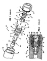
- FIG. 1 - 4 A prior art example of a spray nozzle 10 is shown in Figs. 1 - 4 including a lance adapter 20 and retainer cap 30 components, with a spring valve 101, a clasp device 40 and swirl chamber 50.
- the prior art clasp 40 requires that the wear parts 70,150 be inserted into the housing sideways, so that lateral insertion makes axial alignment of the component parts is not automatically achieved by the dimensional and structural constraints of the component parts.
- the prior art clasp 40 requires that the wear parts 70,150 be housed in individual armour housings 55,75, rather than providing a unitary armour housing that can be fitted with the wear parts 70,150.
- the clasp device 40 has a first end, corresponding to a clasp base 41, seats compressively against an O ring 60 located against an annular shoulder 25 in sealing arrangement within the generally cylindrical lance adapter 20.
- the clasp device 40 comprises a generally cylindrical body 45, extending rearward to the concentric base 41 that is generally concentric therewith and narrower in diameter, having a annular step down to the base 41.
- An opposing end of the cylinder 45 has a seat 43 for a swirl chamber 50 and orifice disc 70 assembly.
- the swirl chamber 50 and orifice disc 70 are very similar to the corresponding wear parts 50,70 utilised in the spray nozzle assembly of the present invention described with reference to Figs. 5a - 11 .
- the seat 43 comprises a pair of opposed raised co-planar partial discs 46 that define therebetween a broad aperture 42with parallel straight sides and radiused ends following the contours of the radiused forward end walls of the cylinder body 45.
- the clasp 40 further includes arm members 44 which each comprise an elongate arm 47 that have a radiused or arced outer surface in cross section following the contour of the cylinder body 45 and an internal planar surface that cooperates with a corresponding pair of opposed flats 51 extending the full length of the housing 55 outer body.
- the arms 47 of the arm members 44 each terminate in a shallow radially inwardly extending hook 48 that is adapted to clamp or pass over the upper edge 52 of the opposed flats 51 of the housing 55, thereby preventing rotation of the housing 55, and therefore importantly the swirl chamber 50, with in the cylindrical body 45.
- Limitation of rotation of the wear parts 50,70 minimises wear and enables the design of a predictable flow path and consistency of flow.
- Prior art swirl chambers have traditionally being cylindrical and permitted rotation within the cap.
- the swirl chamber 50 characteristically has an entrance 53 defining a converging pathway into the cavity 56 of the swirl chamber 50.
- a flat wall 54 of the housing 55 immediately below the entrance 53 allows a sufficient gap between it and the upper wall of the cylindrical body 45 to allow good flow communication between the central bore 33 of the cylindrical body 45 and cavity 56 via a gap 32 defined by the cylindrical body 45 and the lower edge of the flat wall 54.
- the housings 55,75 are loosely fitted within the clasp arms 44 to permit some slack, allow high tolerances and primarily to facilitate the removal of the wear parts after use has gummed them up with the viscous, proteinous, cementitious or gluey flow material.
- the orifice disc 70 compressively abuts an O ring 80 against and with the retainer cap 30.
- This provides an excellent seal between the orifice disc 70 and the retainer cap 30 because the O-ring 80 is captured in an upwardly facing circular groove 71 concentrically set in the upper face of the orifice disc 70.
- the compression of the O-ring 80, trapped in a concentric, upwardly facing seal groove significantly improves seal performance, longevity and wear resistance, and improves the tightness of the fit of the relative components, rather than using a traditional annular seal. In this high-wear application, the compressive seal arrangement is advantageous.
- Figs 3a, b the profiles of the clasp arms 44 are shown.
- the clasp arms are shown to have a flat internal wall 44b which cooperates with the pair of flat walls 51 of the housing 55 to prevent rotation of the housing 55 about the longitudinal axis of the clasp device 40.
- wear parts that are exposed to the high abrasion and pressure of the flowable material are ideally made from costly, extremely hard and abrasion-resistant materials, preferable Tungsten-carbide or the more rudimentary iron-carbon steels.
- the wear parts 50,70 of the present invention are separately formed using extremely hard materials, and then encased or pressed into tightly fitting cases, shrouds or housings 55,75 made of stronger and more workable materials, such as 300 series stainless steel.
- the provision of the clasp 40 permits wear parts 50,70 to be simply removed.
- the clasp device 40 has a threaded outer surface 41a on its base 41 above a pair of opposed flats 49 which facilitate its removal by rotation using a suitable spanner, the threads 41a of the clasp base 41.
- the swirl chamber 50 is located within the housing 55 made of stainless steel to provide a strong swirl chamber assembly with a strong outer casing but hard internal wear surfaces.
- the orifice disc 70 is surrounded by the stainless steel housing 75 which protects it from any damage that might otherwise result from dropping or handling during assembly and disassembly.
- the swirl chamber and the orifice disc are retained in their housings as unitary devices by the peening or machining of a peripheral edge of each housing over these devices.
- other means of providing an annular inwardly radially extending flange or lip known to the skilled person can achieve satisfactory trapping or encasing of the wear part item 50,70 in the respective housing casing 55,75.
- wear items 50,70 are manufactured typically from tungsten carbide which is relatively expensive and brittle. However, they permit the production of narrower more accurate orifice 72 and greater precision in machining and other working of the material. By providing smaller diameter orifice discs 70 and swirl chambers 55 expense is spared because less material is used in their manufacture, as well as the devices 50,70 being protected from damage by their stainless steel housings 55,75.
- wear items 50,70 be provided in situ in their housings 55,75 at the same size as conventional such items which also permits them to be retro fitted to existing spray nozzle assemblies and used as wear part consumables therein.
- the orifice disc 70 is, in itself, very similar to that used in the present invention, except that it has slight flattened sides 69.
- the orifice disc 70 is a substantially circular thin disc shape that is 1 - 2mm in height and about 14 - 20mm in diameter, but noting that these dimensions are merely suggestive and the invention is not limited to orifices having particular dimensions.
- the housing 75 On the sides of the housing 75 corresponding to the position where the clasp hook 48 overhangs the housing 75, the housing 75 has opposed flat sides with a recessed section 74 having a narrow and shallow ledge inclining upwardly towards the orifice 72.
- the recess 74 provides a resting positions in which the hook 48 is adapted to nest and includes a pair of spaced knobs or small ramps 77, one at each end of the recess 74, that laterally retain the hook, overhang or catch 48 and provides a ramp over which the ends of the hook 48 may ride on insertion or removal, noting that there is some play purposely incorporated in the fit of the component parts 40,44,55,75.
- the orifice 72 is centrally located in the orifice disc 70. Concentrically placed around the periphery of the disc 70 on its upper surface is a circular groove 71 adapted to receive an O-ring 80 as previously described. The groove is sufficiently deep to retain the O-ring 80, but sufficiently shallow to allow the O-ring 80 to sit partially proud of the upper disc 70 surface.
- the orifice 72 is finely machined or otherwise formed to low tolerance which is made possible by the use of hard and workable alloys.
- the orifice 72 has a flare mouth or inlet 72a located centrally on the orifice's 70 underside surface to facilitate pressurised flow into and through the orifice 72. Different applications will require different sized apertures for the orifice 72.
- the orifice disc upper surface 78 includes an annular peripheral bevelled or cammed edge 79 over which the upper inner walls of the housing75 are peened or worked to provide a smooth transitional surface from the housing upper peripheral surface to that of the orifice disc 70 and ensure a good mating relationship.
- the lower side walls are similarly bevelled or radiused to facilitate peening or working of a inward extending radial flange of the housings 55,75 to extend over the upper and lower peripheries of the orifice disc 70.
- a check valve is provided within the spray nozzle assembly.
- the first end 41 of the clasp passes generally over the perforated sleeve 90 covering the valve spring 100.
- This first end of the clasp in turn seats compressively against an O ring 60 located against a shoulder 25 within the lance adapter 20 to form a seal.
- the lance adapter 20 and end cap 30 engage by means of a screw thread 31 located within one end of the lance adapter and the exterior of one end of the end cap the arrangement being such that when screw connection of these components has been effected no external thread is present which could be damaged by contact.
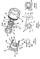
- FIG. 5a - 6d Another embodiment of the inventive clasp arrangement is shown in Figures 5a - 6d .
- a smaller (so-called "mini") spray nozzle arrangement is presented as compared to the "maxi" prior art clasp that is shown in Figures 1 and 3 - 4c .
- a substantially cylindrical protective shell or casing in the form of a housing 110 having a central bore 112 that is axially continuous through lower, intermediate and upper chambers 114, 116,118.
- the lower most chamber 114 is the inlet for the clasp arrangement and receives incoming flow material into the nozzle.
- the lower outer surface of the housing 110 includes a threaded portion 120 that is adapted to engage the internal thread in a nozzle cap 30. Similar to the valve arrangement 101 shown in Fig. 2 , the lower chamber 114 receives the perforated sleeve 90 of valve 101 and telescopically the other valve 101 components, including the spring 100.
- the arrangement includes a swirl chamber 150 that may be identical to that shown in Figs. 1 - 2 , or may be dimensioned differently to give the chamber 150 different characteristics of atomisation and spray pattern, velocity of spray and density of application, etc.
- the swirl cavity 156 in this case is very shallow and the broad wall 154 immediately below the mouth 153 is high relative to the broad wall 54 of the housing 55 in Fig. 1 .
- the swirl chamber 150 further includes a longitudinal groove key 157 machined or otherwise formed the full height of the predominantly cylindrical wall 158 of the swirl chamber 150.
- the groove key 157 provides a lock on axial rotation of the swirl chamber 150 when housed in the cylindrical housing 110.
- the orifice disc 70 may be identical to that shown in Fig. 1 or may be varied with respect to the orifice size 72. There is bulk economy in providing swirl chambers 150 and orifice discs 70 of identical outer dimensions so that one size fits all arrangements.
- the orifice disc 70 is shown in Fig. 6c with the O-ring 80 seated in the circular groove 71.
- the invention enables the same sized swirl chambers 150 and orifice discs 70 to be used in spray nozzles 10 of different sizes and capacities, such as mini and maxi spray nozzles, whilst advantageously protecting wear parts 50,70,150 made from hard and correspondingly brittle materials with housings 55,75,110 made from strong and resilient materials, irrespective of the spray nozzle bore sizes in the cap 30 and lance adapter 20.
- the cylindrical housing 110 is adapted to house both the swirl chambers 150 and orifice discs 70 in axial relationship in the chamber 118 in a snug fit but allowing a small amount of play to facilitate removal and replacement of the consumable wear parts 70,150 when gummed up by dried flowed material, such as proteinous milk.
- the flow path from the lance adaptor 20 through to the central bore 112 occurs through a pair of opposed large slots 132 formed in the cylindrical wall 134 which provide the entrance for the flow material into the intermediate chamber 116.
- annular ledge 136 Located above the intermediate chamber 116 is an annular ledge 136 providing a seat on which the swirl chamber 150 may rest when inserted into the upper chamber 118.
- the cylindrical wall 134 includes the large generally rectangular opening 135 that is adapted to be in registration with the cavity mouth 153 of the swirl chamber 150.
- Circumferential registration of the swirl chamber 150 is achieved by providing a registration arm or post 137 defined by two spaced longitudinal slots 138 in the wall 134, the post 137 having a key ridge 139 extending down a substantial portion of its length on the post's 137 inside surface.
- the ridge may be two or more longitudinally aligned protrusions, but is preferably a continuous ridge starting immediately underneath the position that the orifice disc 70 takes up above the swirl chamber 150 in the upper chamber 118 to ensure that a standard circular disc 70 may be used, and depending down to the ledge 136.
- the cylindrical housing 110 includes an open top 140 through which the swirl chamber 150 is first axially inserted by an operator, its bevelled peripheral lower edge 159 assisting the lower edge's 159 passage past the upper end of the post which includes a shallow detent, clasp, catch or stop 145 comprising a protrusion extending radially inwardly to trap the orifice disc 70 in place once inserted after the swirl chamber 150.
- the post 137 is resiliently deflectable radially outwardly due to its narrow width despite the strengthening properties of the ridge 137 so that the orifice disc 70 may ride passed the catch 145 and nest in the very top of the upper chamber 118.
- the catch 145 forms part of a radially inwardly extending lip 146 that continues along the inner upper surface of the cylindrical wall 134 and gradually tapers off.
- the cylindrical shape of the orifice disc 70 albeit shallow as it is and its tight axial fit in the downstream or upper chamber 118, means that it is difficult to tilt out of axial alignment and is so held by the non-symmetrical detent 145 on one side of the upper chamber 118.
- the upper peripheral edge of the orifice disc 70a comprises a radial step 73a with an either stepped transition in diameter between the top surface 74a and the side wall 75b, or the axial step 73a comprises a radial concave curve in profile.
- the radial step is stepped and provides a horizontal upper surface immediately above the side wall 75b on which the protrusions 145,146 may engage, so that the protrusions 145,146 engage under radial inward tension imposed by the tendency of the post 137 to press inward to urge the protrusion 146 into the annular radial step 73a.
- the radial step 73a is uniform annularly about the upper edge of the orifice disc 70a, so that circumferential alignment of the orifice disc 70a is not required.
- the lower peripheral edge of the orifice disc 70a may be chamfered or bevelled uniform circumferentially to facilitate the insertion of the orifice disc 70a into the housing chamber 118.
- the radial step may be between 0.2 - and 1.0mm in size.
- the radial step 73a may be 0. 4 to 0.8mm in size.
- the radial step is preferably about 0.5 - 0.7mm, and most preferably about 0.6mm in size.
- the post protrusion 145 may extend radially inwardly to a greater extent than the retaining wall protrusion 146.
- the retaining wall protrusion 146 may be a shallow radial protrusion that extends partially or fully circumferentially around the upper region of the retaining wall 134a.
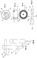
- a special cam tool 160 shown in Figs. 8a and 8b , may be used to lever the wear parts 70,150 out of the housing 110 when required.
- the cam tool includes a central shaft and a crucifix handle 162 for manipulating the tool 160.
- the remote end of the shaft 161 terminates in a cam device comprising a cam disc 164 intermediate a spindle 165.
- the cam device 163 is inserted into one of the large slots 132 and through to the opposed slot 132, so that the cam disc 134 in located immediately underneath the swirl chamber 150 with the cam disc substantially in alignment with the slots 132.
- the cam disc 163 supported by the spindle 165 bearing against the lower edges of the slots 132, rides up against the underside 166 of the swirl chamber 150 whereby to apply upward force against the swirl chamber 150 so that the orifice disc 70 is forced passed the catch 145 and out of the upper chamber 118.
- the nozzle 210 includes a nozzle cap 230 threadably engaged to a lance adapter 220.
- the nozzle 210 includes a wear parts housing 240 threadably engaged to the nozzle cap 230 by an outer threaded surface 241a of the housing 240 engaging an internally threaded bore 241b in the nozzle cap 230.
- the housing 240 traps the wear parts, a swirl chamber 250 and an orifice disc 270, in concentric relationship by providing a self-aligning combination of bevelled or tapered edges 259 and 273 that cooperate with similarly tapered annular surfaces within the housing 240 to ensure that as the orifice disc 270 is pressed passed the claw 245 at the top of the arm 237, the respective tapered surfaces of the wear parts 250,270 and the internal surfaces of the housing 240, cooperate to concentrically align part in the housing 240 in a fixed arrangement with minimal play between the wear parts 250,270 and the housing 240.
- an axially compressed seal 280 in the upper surface 278 of the orifice disc 270 enhances the axial alignment and compression of the various parts 250,270,240 in the cavity defined between the nozzle cap 230 and the lance adapter 220. Whereas a radial O-ring might fail and be forced through the orifice 285, the compression seal 280 is much less likely to fail and its effectiveness is improved by the axial compression of the overall arrangement.
- the components 250,270,240 can be secured in a tight fit with negligible play because the axial engagement of the nozzle cap 230 and the housing 240 means that a large amount of torque can be applied to each component requiring disassembly to overcome the adhesive forces of the dried spray material.
- spanners can be used for disassembly of the threadably engaged parts 220,230,240 rather than an arbor press or other specialist disassembly device. Lands or flats 249a-c are provided for engagement by a spanner.
- the upper end of the housing wall 234 slopes downwardly towards an opening 235 in the housing wall 234, the opening 235 being for the purpose of registration with the mouth 253 of the swirl chamber 250.
- the inclination downwards of the upper edges 287 of the wall 234 protect the edges from damage and wear to which the upper opening 286 of the housing is exposed with the entry and removal of the wear parts 250, 270.
- the retaining edge 245 extends substantially around the upper edge 287 for about 180 -270 degrees.
- the arm 237 is sufficiently resiliently deflectable to permit the entry of the wear parts into the housing by manual force, although a special tool 160 is required to remove the wear parts 250,270 from the housing as described with reference to Figs. 8a and 8b .
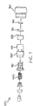
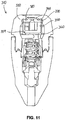
- Fig. 11 there is shown a spray nozzle assembly similar to that shown in Figs. 9a - 9b , but showing the respective taper lower periphery 359 of a swirl chamber 350 that cooperates with a corresponding and parallel internal annular angled corner forming a seat 360 in the internal wall surface of the housing 340.
- This enables a multi-stage procedure for achieving concentricity and axial alignment of the wear parts 350,370 in which the wear parts may be eccentrically aligned once initially inserted into the housing 340, the housing 340 comprising claws 345 that grip the upper chamfered edge 373 of an orifice disc 370.
- an O-ring 380 in the orifice disc 370 symmetrically bears down of the orifice disc 370 and forces the self-alignment of the wear part 350 by the operation of the cooperation of the angled annular surfaces 359,360.
Description
- This invention relates a clasp for a spray nozzle assembly, particularly the type of spray nozzle having a check valve which is specifically adapted to be used with spray drying nozzles, but can also be used in association with other nozzles.
- The following references to and descriptions of prior proposals or products are not intended to be, and are not to be construed as, statements or admissions of common general knowledge in the art. In particular, the following prior art discussion does not relate to what is commonly or well known by the person skilled in the art, but assists in the understanding of the inventive step of the present invention of which the identification of pertinent prior art proposals is but one part.
- For ease of description, we shall refer to such a spray nozzle assembly in terms of one associated with spray drying of milk, but it is envisaged that the spray nozzle assembly made according to the invention can be used to spray other fluids, particularly fluids having a tendency to coagulate or for its residue to assume a viscous, solid or gluey consistency having a tendency to gum or jam components parts, making their removal for replacement or servicing more difficult.
- In general spray nozzles which are provided with swirl chambers and orifice discs have these components manufactured from tungsten carbide or the like which is very hard but also brittle and prone to damage when dropped or otherwise roughly treated during assembly and disassembly.
- When ordinary spray nozzles are used for spray drying milk, a certain percentage of the liquid simply fall as drops from the nozzles, without being atomized, and this material can well lead to spoiling of the product.
- To avoid this problem, a unitary check valve was developed for spray drying nozzles, and other nozzles, which caused little restriction in the flow through the nozzle and which, at the same time, did not have any parts, or break-off parts thereof, likely to be passed into the fluid stream.
- Conventional check valves, however, have sealing problems when operated at high pressures and are not necessarily as compact as would be desirable.
- Prior art nozzles generally have stepped annular shoulders that ensure coaxial alignment and concentricity of respective, axially aligned wear parts. However, because the flow material (like proteinous milk products) can set or dry to a viscous or glue-like consistency, it is necessary to build in clearance gaps including radial gaps (lateral gaps to the side of the wear parts) or axial (longitudinal gaps between the wear parts and the nozzle components axially containing them). These gaps between the wear parts and the nozzle cylinder need to provide sufficient play or movability of the respective parts relative to each other to facilitate removal for replacement, cleaning and repair. Also, normal manufacturing tolerances dictate a gap requirement to prevent component jams axially and radially. Therefore the prior art designs inherently lack accurate concentricity which has adverse affects on spray nozzle performance, predictability of spay patterns and/or spray line production. Stepped annular shoulders in the internal wall of the nozzle cap mean prior art caps are structurally weak and introduce stress concentrations at the sharp angled corners within these steps.
-
DE 10 2006 025301 A1 discloses a jet regulator designed in such a way that is mountable and demountable in a simple and fast manner. - It is an object of the invention to ameliorate the above problems associated with spray nozzles, and particularly those used in association with check valves, and to provide general improvements in the assembly and construction of spray nozzle components.
- The invention in one aspect provides one or more housings within a spray nozzle assembly for protecting one or more wear components, such as the swirl chamber and orifice disc from damage.
- In one aspect of the invention, there is provided:
a clasp for a spray nozzle assembly, wherein the spray nozzle assembly includes a spray nozzle and a wear part releasably trapped in a protective housing, comprising the protective housing with a housing chamber having a lower base on which the wear part may be seated, an upper opening through which the wear part may axially enter the housing chamber or be removed therefrom, and a chamber wall comprising a substantially rigid, part-cylindrical retaining wall having a first upper radially inwardly extending protrusion and at least one resiliently deflectable wall section having a further upper radially inwardly extending protrusion. - The first and further protrusions may be adapted to radially and axially releasably retain the wear part in the housing chamber in substantially concentric relationship to the housing chamber. This may, in part, be achieved by providing that the protective housing is axially screwed into the complementarily threaded spray nozzle to achieve concentricity. The extent of axial engagement of the protective housing in the spray nozzle may not affect the registration of the swirl chamber relative to the protective housing so that fluid flow is not affected because the wear part is located against rotation in the housing chamber. Furthermore, the wear part may be adapted to be concentrically located within the housing chamber without long longitudinally aligned surfaces. This may be achieved by providing the housing base with a chamfered inner wall. The chamfered inner wall may cooperate with a bevelled lower circumferential edge of the wear part to centre the wear part in the housing chamber.
- The radial extent of the first protrusion may be substantially smaller than the radial extent of the further protrusion. The first protrusion extending from a substantially rigid structure is radially smaller to permit the passage of the wear part through the housing opening, so that the deflectable wall section does the deflecting to permit entry or exit of the wear part.
- However, the further protrusion is significantly radially larger as it is mounted to the deflectable wall section and preferably occupies a much smaller arc of the housing wall in a diametrically opposed position relative to the first protrusion.
- The part-cylindrical retaining wall may extend circumferentially to form an arc that extends greater than halfway around the cylindrical chamber or describes an angle of greater than 180 degrees. In comparison, the deflectable wall section may be dimensioned to be circumferentially small in width in that its arc describes an angle less than 30 degrees, and preferably about 20 degrees.
- The protective housing is preferably generally cylindrical. The deflectable wall section is preferably in the form of a post defined by a slot in the housing chamber wall either side of the post. The inwardly extending protrusion may be located at or near the upper or downstream end of the housing wall. The further protrusion is preferably adapted to prevent the wear part from inadvertently axially escaping from the housing chamber.
- The wear part may comprise an orifice disc. The wear part or the spray nozzle assembly may additionally include a swirl chamber. The housing chamber inner wall includes a longitudinally aligned projection that provides an axial key for the swirl chamber. The axial key preferably cooperates with a complementary feature on an outer side wall of the wear part to prevent the wear part from rotating in the housing chamber. The swirl chamber entrance or cavity mouth is then always in registry with an opening in the protective housing so that good flow is ensured.
- The axial key may extend along the deflectable wall as a longitudinally aligned reinforcing rib that resists permanent deformation of the deflectable wall.
- In the housing chamber, the swirl chamber may support the orifice disc that is aligned axially with the housing chamber and the swirl chamber. The orifice disc may be sized to be axially trapped immediately under the first and further protrusions as well as radially trapped by the retaining and deflectable walls. The swirl chamber may be sized slightly radially smaller than the orifice disc to clear the first and further protrusions, so that the orifice disc holds the swirl chamber in the housing chamber.
- The base of the post may be located at the base of the housing or may be intermediate the height of the housing chamber wall. The axial key may extend upstream towards the base of the housing chamber beyond the base of the deflectable wall section.
- An upper peripheral region of the wear part may have a tapered, bevelled, stepped or other wall feature that is adapted to cooperate with the first and further protrusions. The wear part may have a radial step such that the top of the wear part is radially smaller than the outer step portion of the wear part, the radial step engaging with the first and further protrusions.
- The protective housing wall may extend upstream of the base of the housing chamber. The protective housing wall may have a slot that provides access to an intermediate chamber upstream of the housing chamber. The slot may permit the insertion of a wear part removing tool. The slot and the housing opening, registered with the swirl chamber mouth, may provide flow communication between the intermediate chamber and the housing chamber. The slot may be accessible by a cam tool. The cam tool may have a disc cam intermediate a shaft to enable the disc cam to be rotated and to bear against the wear part to overcome a retaining force of the protrusions. This may be achieved by forcing the deflection of the deflectable wall section to allow the wear part to be removed from the protective housing.
- The deflectable wall section may comprise a post defined by a slot in the chamber wall either side of the post. The post may include an inwardly extending protuberance at or near its end which is adapted to prevent the wear part from axially escaping from the chamber.
- The wear part may be made from a hard and abrasion resistant material such as a ceramic, metal or plastic component or a composite thereof. Abrasion resistant plastic materials may be achieved by impregnating polymeric materials with abrasion resistance fibres or particles such as glass, other silicon-based minerals and carbides. Preferably the wear part is made from a metal alloy, metal-mineral composite or metal -carbide, such as iron or tungsten carbide. As such wear parts are hard=wearing but prone to brittleness It is preferred that the housing is manufactured from a durable material such as a metal alloy, including steel, and preferably a corrosion resistant metal, such as stainless steel. However, any appropriate material is included within the scope of the invention.
- In another aspect of the invention, there is provided a spray nozzle assembly including at least one wear part made from a hard and abrasion resistant material and a protective housing made from a strong and resilient material and having a chamber adapted to receive one or more of the wear parts in releasably trapped relationship, the chamber having a wall including an arm or post adjacent at least one slot in the chamber wall, the post including a protuberance extending inwardly towards the center of the housing, the protuberance at or near the end of the arm or post and adapted to prevent the wear part from axially inadvertently escaping from the chamber.
- Hereinafter, reference to the post will include reference to the arm or post. The chamber is preferably a downstream chamber.
- The housing and the downstream chamber are preferably generally cylindrical, but may include a number of symmetrical or irregular cross sectional shapes, particularly to prevent axial rotation of the wear parts. The downstream chamber is preferably open-ended.
- The housing may be a generally hollow cylinder. The housing may have shoulders for seating the wear parts.
- Preferably, the present housing provides tapered seats for wear parts and the wear parts have complementary annular tapered or bevelled edges. The tapering of the edges and corners enables the wear parts to cooperate with the housing seats to achieve self-alignment and concentricity as the parts are axially compressed into axial alignment on assembly. The wear parts naturally coaxially align with the housing and, as they are axially compressed in the housing they align in fixed concentric and coaxial alignment. This arrangement provides for accurate alignment of orifices, apertures and openings for maximum efficiency and predictability of flow and spray characteristics. Concentricity is achieved by providing tapered surfaces, such as angular, radiused, curved, chamfered or bevelled surfaces, over short axial or longitudinal distances.
- It is noted that prior art arrangements provided large longitudinal sections to locate parts axially. Concentricity in the present invention may be achieved via angular type interfaces over a short distance of, preferably 0.2 - 2.0mm, and still more preferably, 0.4 0 1.0 mm. These concentric features may taper concentrically and act as a guide to centre the wear part. By the use of short angular or bevelled leading edges, rather than the longer longitudinally radial location of the prior art steps, this reduces adhesion and the size of wear surfaces, particularly advantageous at points of concentricity. Such angular and concentric surface features facilitate and determine concentricity of the wear parts. One could provide shorter longitudinally aligned radial walls, but still need gaps to prevent adhesion. Full concentricity may be achieved only once the housing is compressed by an axial load in the cap to achieve full alignment. The tapered surfaces may be identical in angle. Or the tapered surfaces may be different, for example, concentricity may be provided thus:
- Radius to radius
- Radius into taper engagement about a radius
- Parallel taper to taper engagement
- Varying taper angular point engagement
- This provides a multiple step alignment - the clasp first aligns, followed by axial compression via an O-ring concentrically arranged in the top surface of an orifice disk which forces the lower tapered surfaces into alignment. Concentricity is therefore achieved via an angular type interface over a short distance, rather than the longer longitudinally aligned radial location of the steps, thus reducing adhesion surface at points which determine concentricity of the wear parts.
- Another aspect of the invention is that the nozzle component parts are screw fitted for axial engagement. This provides a particular functional advantage over other wear part installations that are not screw fitted, because in prior versions, a certain amount of longitudinal radial gap is required to enable removal and replacement of wear parts to be facilitated. In the present arrangement, the wear parts enclosed in the housing are compressed into a tightly fitting axial alignment. Prior art arrangements require an arbor press, such as a manually levered mandrel press, to disengage thickly bound parts glued together by sticky, viscous or dried materials. The axial screw engagement of the housing to the nozzle component such as the nozzle cap assists concentricity of the component parts, achieves a tight fitting arrangement for better flow and predictability of spray properties, and provides an in-built arbor press or means to apply high torque to the component parts to break the adhesion caused by the dried material and enable replacement of the parts. The internal wall of the nozzle cap includes an annular guide to keep the housing wall and the post radially inwardly supported against flexing until the housing is partially removed from the nozzle cap. The internal wall of the nozzle cap includes an annular stress relieving radiused recess. The bottom edge of the recess forms a radially inward clasp or grip retention diameter or annular guide to stop the post, arms or claws from releasing grip of the wear parts until the "glue" is broken and the housing has been removed at least partially from the nozzle cap.
- Moreover, the protective housing extends the life of the wear parts considerably. Excessive eccentricity affects a spray nozzles performance. If the geometry is off center, it makes a nozzle less efficient and requires greater pressure of the flow material to deliver adequate flow of the product through the nozzle vortex, including the swirl chamber and the cavities defined by the nozzle.
- Because concentricity of the component parts is achieved, the nozzle barrel components, such as the nozzle cap, may be engineered differently to avoid the sharp angles required in the prior art to achieve concentricity and the nozzle cap structures are not required to achieve alignment of the housing or wear parts. The nozzle head internal structures close to the orifice may be radiused in profile to minimise the concentration of stress areas or points associated with sharp edges by distributing the stress load over a wider surface area of the radiused or curved annular concave structure.
- The wear part may include an orifice disc and/or a swirl chamber. The wear parts may be seated, trapped, fixed or otherwise located in the downstream chamber. The swirl chamber may be adjacent the orifice disc which is preferably aligned axially therewith. The orifice disc may be sized to be trapped immediately under the retaining edge or protuberance.
- The post is preferably resiliently deflectable to permit the wear part to enter or be removed from the downstream chamber upon application of sufficient force, but be retained against axial displacement at rest. The base of the post may be located intermediate the height of the chamber wall or may extend down to the base.
- A longitudinally aligned key may extend along part or all of the length of the chamber wall. The key preferably cooperates with a complementary feature on the side wall of the wear part to prevent the wear part, particularly the swirl chamber, from rotating about its axis in the downstream chamber. The key advantageously provides structural reinforcement of the post and may extend beyond the post along the inside chamber wall down to or towards the base. However, the key or longitudinally aligned and extending ridge, rib or protruberence, may be an external feature located other than on the post.
- The complementary feature may be a longitudinally aligned groove. The key may be one or more protrusions raised relative to the inner surface of the post towards the axial centre of the downstream chamber and aligned longitudinally and parallel to the chamber axis. The key is preferably a ridge. The ridge may extend the full length of the post and down to a base of the downstream chamber.
- The downstream chamber base may be an annular ledge. The base may comprise circumferentially spaced radially inwardly extending protrusions. The base may comprise any other seat device that prevents axial displacement of the wear part away from the retaining edge or protuberance to below the seat device within the housing. The top surface of the outer surface of the top of the post and the inner chamber wall may be a radius to radius engagement or abutment relationship.
- The chamber wall may include a side opening. The side opening may define one side of the post. However, to protect the post, the post may be defined by a slot either side of the post. The chamber wall may extend further to the opening from a slot adjacent the arm or post. The side opening may register with a mouth of a cavity of the swirl chamber. The side opening may provide flow communication between an intermediate chamber of the housing and the swirl chamber via the cavity of the nozzle encompassing the housing.
- The housing may include a wall having a at least one opening, such as a slot, providing access to the intermediate chamber below the downstream chamber. The slot may be accessed by a cam tool. The cam tool may have a disc cam intermediate a shaft to enable the disc cam to be rotated and to bear against the one or more wear parts. The cam may overcome a retaining force of the protuberance by urging the wear part to bear against the retaining edge thereby deflecting the post to allow the at least one wear part to be removed. The slot preferably provides flow communication between a lower chamber and the intermediate chamber.
- It is further preferred that the orifice disc and the swirl chamber be retained in one or more housings by means of a peened or machined retaining edge about its periphery thus making these parts and respective housing a unitary assembly. The retaining edge preferably extends radially inwardly.
- The invention in a second aspect provides a clasp device used to locate and secure the swirl chamber and orifice disc components within the spray nozzle retainer cap.
- The arrangement is such that the wear parts and housings clip in to the clasp device in which they are retained by means of the arm members. The precise means whereby this is effected is not restricted in the invention. A preferred means, however, is the engagement of the terminal ends of the arms with corresponding lugs on the engaging flats of the wear parts.
- The invention in a third aspect is the provision within a spray nozzle assembly of a first O ring which seats within a lance adapter and is held compressively by the retainer cap when assembled and a second O ring within the retainer cap which compressively seals under the load applied by a clasp used to locate the swirl chamber and orifice disc components.
- The arrangement is such that each O ring is compressed independently of the other.
- Previously such sealing had been effected by means of flat washers or axial gland seals, both of these being less effective at high pressures. This could be partially addressed with support backup rings however are difficult to install on a regular basis and expensive to replace and have limitations at elevated pressures. The use of the O rings as described here addresses these problems and is highly effective in such a static arrangement at much higher pressure levels than previously possible.
- In a further aspect of the invention wear parts in a spray nozzle are provided with durable housings into which they are located.
- It is preferred that these housings be applied to parts such as swirl chambers and orifice discs.
- In a further embodiment of the invention a swirl chamber or orifice plate can be provided which is smaller in diameter than that which would be conventionally used such that, when a housing is applied about their peripheries, the resulting diameter of each is then that of conventional such devices.
- It is therefore preferred that these be able to be retro fitted to existing spray nozzle assemblies.
- In an embodiment of the invention in which a check valve is included the perforated sleeve covering the valve is provided with locating pins positioned at the end of the sleeve most remote from the nozzle in order to minimise the length of the spray nozzle assembly.
- The invention in a fourth aspect provides a threaded end on the retainer cap which engages with an internal thread in the lance adapter such that no exterior threads are provided on the assembled spray nozzle assembly and as such damage to external threads cannot occur.
- Possible and preferred features of the present features of the present invention will now be described with particular reference to the accompanying drawings. However, it is to be understood that the features illustrated in and described with reference to the drawings are not to be construed as limiting on the scope of the invention. In the drawings:
-
FIG. 1 shows an exploded diagram of the components of a prior art spray nozzle assembly; -
FIG. 2 shows an assembled section view of the prior art nozzle assembly shown inFig. 1 ; -
FIG. 3 is a perspective view of a component of the prior art clasp device shown inFig. 1 with an arm member shown from additional partial side and top plan perspectives; -
FIG. 4a is an exploded perspective view of part of the prior art assembly shown inFig. 1 with an orifice disc made according to an aspect of the present invention shown from top plan and side perspectives; -
FIG. 4b is a top plan view of an orifice disc shown inFig. 4a in a prior art armour housing; -
FIG. 5a is a side view of a cylindrical housing according to a preferred embodiment of the invention; -
FIG. 5b is another side view of the cylindrical housing shown inFig. 5a rotated about 90 degrees; -
FIG. 6a is a top plan view of a swirl chamber according to the preferred embodiment; -
FIG. 6b is a side view of the swirl chamber shown inFig. 6a ; -
FIG. 6c is a top plan view of an orifice disc according to the preferred embodiment; -
FIG. 6d is a side view of the orifice disc shown inFig. 6c ; -
FIG. 7 is an exploded view of a spray nozzle assembly according to the preferred embodiment; -
FIG. 8a is a front elevation of a cam tool according to the preferred embodiment; -
FIG. 8b is a side elevation of the cam tool shown inFig. 8a ; -
Figures 9a and 9b are section views of a spray nozzle assembly made according to a second embodiment of the invention similar to the preferred embodiment; -
Figure 10 is an exploded perspective view of the spray nozzle made according to the second embodiment; and -
Figure 11 is a sectional view of a spray nozzle assembly according to a third embodiment of the invention. - A prior art example of a spray nozzle 10 is shown in
Figs. 1 - 4 including a lance adapter 20 andretainer cap 30 components, with aspring valve 101, aclasp device 40 andswirl chamber 50. Theprior art clasp 40 requires that the wear parts 70,150 be inserted into the housing sideways, so that lateral insertion makes axial alignment of the component parts is not automatically achieved by the dimensional and structural constraints of the component parts. Theprior art clasp 40 requires that the wear parts 70,150 be housed inindividual armour housings - The
clasp device 40 has a first end, corresponding to aclasp base 41, seats compressively against anO ring 60 located against anannular shoulder 25 in sealing arrangement within the generally cylindrical lance adapter 20. - The
clasp device 40 comprises a generallycylindrical body 45, extending rearward to theconcentric base 41 that is generally concentric therewith and narrower in diameter, having a annular step down to thebase 41. An opposing end of thecylinder 45 has a seat 43 for aswirl chamber 50 andorifice disc 70 assembly. Theswirl chamber 50 andorifice disc 70 are very similar to the correspondingwear parts Figs. 5a - 11 . - The seat 43 comprises a pair of opposed raised co-planar
partial discs 46 that define therebetween a broad aperture 42with parallel straight sides and radiused ends following the contours of the radiused forward end walls of thecylinder body 45. Theclasp 40 further includes arm members 44 which each comprise an elongate arm 47 that have a radiused or arced outer surface in cross section following the contour of thecylinder body 45 and an internal planar surface that cooperates with a corresponding pair ofopposed flats 51 extending the full length of thehousing 55 outer body. The arms 47 of the arm members 44 each terminate in a shallow radially inwardly extendinghook 48 that is adapted to clamp or pass over theupper edge 52 of theopposed flats 51 of thehousing 55, thereby preventing rotation of thehousing 55, and therefore importantly theswirl chamber 50, with in thecylindrical body 45. Limitation of rotation of thewear parts - The
swirl chamber 50 characteristically has anentrance 53 defining a converging pathway into thecavity 56 of theswirl chamber 50. A flat wall 54 of thehousing 55 immediately below theentrance 53 allows a sufficient gap between it and the upper wall of thecylindrical body 45 to allow good flow communication between thecentral bore 33 of thecylindrical body 45 andcavity 56 via agap 32 defined by thecylindrical body 45 and the lower edge of the flat wall 54. Thehousings - The
orifice disc 70 compressively abuts anO ring 80 against and with theretainer cap 30. This provides an excellent seal between theorifice disc 70 and theretainer cap 30 because the O-ring 80 is captured in an upwardly facingcircular groove 71 concentrically set in the upper face of theorifice disc 70. The compression of the O-ring 80, trapped in a concentric, upwardly facing seal groove, significantly improves seal performance, longevity and wear resistance, and improves the tightness of the fit of the relative components, rather than using a traditional annular seal. In this high-wear application, the compressive seal arrangement is advantageous. - In
Figs 3a, b the profiles of the clasp arms 44 are shown. InFig. 3a , the clasp arms are shown to have a flatinternal wall 44b which cooperates with the pair offlat walls 51 of thehousing 55 to prevent rotation of thehousing 55 about the longitudinal axis of theclasp device 40. - During use of such a spray nozzle 10, it is common for the material being sprayed to adhere to the contacting components. Wear parts that are exposed to the high abrasion and pressure of the flowable material are ideally made from costly, extremely hard and abrasion-resistant materials, preferable Tungsten-carbide or the more rudimentary iron-carbon steels. However because of their hardness, such materials are generally brittle, lacking in strength. Therefore, advantageously, the
wear parts housings clasp 40 permits wearparts clasp device 40 has a threadedouter surface 41a on itsbase 41 above a pair ofopposed flats 49 which facilitate its removal by rotation using a suitable spanner, thethreads 41a of theclasp base 41. Upon rotation of theclasp 40 relative to theretainer cap 30 damage to the wear parts is avoided that is caused by the conventional pressing out of the wear parts by an arbor press or other such means. - The
swirl chamber 50 is located within thehousing 55 made of stainless steel to provide a strong swirl chamber assembly with a strong outer casing but hard internal wear surfaces. Similarly, theorifice disc 70 is surrounded by thestainless steel housing 75 which protects it from any damage that might otherwise result from dropping or handling during assembly and disassembly. - The swirl chamber and the orifice disc are retained in their housings as unitary devices by the peening or machining of a peripheral edge of each housing over these devices. Of course other means of providing an annular inwardly radially extending flange or lip known to the skilled person can achieve satisfactory trapping or encasing of the
wear part item respective housing casing - These wear
items accurate orifice 72 and greater precision in machining and other working of the material. By providing smallerdiameter orifice discs 70 andswirl chambers 55 expense is spared because less material is used in their manufacture, as well as thedevices stainless steel housings wear part items housings components consumable products consumables clasp device 40 which permits some axial movement to facilitate removal and replacement. - It is also envisaged that these
wear items housings - With reference to
Figs. 4a - 4c , there is shown theorifice disc 70 andhousing 75 in greater detail. Theorifice disc 70 is, in itself, very similar to that used in the present invention, except that it has slight flattened sides 69. Theorifice disc 70 is a substantially circular thin disc shape that is 1 - 2mm in height and about 14 - 20mm in diameter, but noting that these dimensions are merely suggestive and the invention is not limited to orifices having particular dimensions. On the sides of thehousing 75 corresponding to the position where theclasp hook 48 overhangs thehousing 75, thehousing 75 has opposed flat sides with a recessedsection 74 having a narrow and shallow ledge inclining upwardly towards theorifice 72. Therecess 74 provides a resting positions in which thehook 48 is adapted to nest and includes a pair of spaced knobs orsmall ramps 77, one at each end of therecess 74, that laterally retain the hook, overhang or catch 48 and provides a ramp over which the ends of thehook 48 may ride on insertion or removal, noting that there is some play purposely incorporated in the fit of thecomponent parts - The
orifice 72 is centrally located in theorifice disc 70. Concentrically placed around the periphery of thedisc 70 on its upper surface is acircular groove 71 adapted to receive an O-ring 80 as previously described. The groove is sufficiently deep to retain the O-ring 80, but sufficiently shallow to allow the O-ring 80 to sit partially proud of theupper disc 70 surface. Theorifice 72 is finely machined or otherwise formed to low tolerance which is made possible by the use of hard and workable alloys. Theorifice 72 has a flare mouth orinlet 72a located centrally on the orifice's 70 underside surface to facilitate pressurised flow into and through theorifice 72. Different applications will require different sized apertures for theorifice 72. - The orifice disc
upper surface 78 includes an annular peripheral bevelled orcammed edge 79 over which the upper inner walls of the housing75 are peened or worked to provide a smooth transitional surface from the housing upper peripheral surface to that of theorifice disc 70 and ensure a good mating relationship. The lower side walls are similarly bevelled or radiused to facilitate peening or working of a inward extending radial flange of thehousings orifice disc 70. - Although the materials described are preferred they are not restricted in the invention.
- In a second aspect of the prior art shown in
Fig. 2 which helps to understand the present invention, a check valve is provided within the spray nozzle assembly. In this embodiment thefirst end 41 of the clasp passes generally over theperforated sleeve 90 covering thevalve spring 100. This first end of the clasp in turn seats compressively against anO ring 60 located against ashoulder 25 within the lance adapter 20 to form a seal. - The lance adapter 20 and
end cap 30 engage by means of ascrew thread 31 located within one end of the lance adapter and the exterior of one end of the end cap the arrangement being such that when screw connection of these components has been effected no external thread is present which could be damaged by contact. - Another embodiment of the inventive clasp arrangement is shown in
Figures 5a - 6d . A smaller (so-called "mini") spray nozzle arrangement is presented as compared to the "maxi" prior art clasp that is shown inFigures 1 and3 - 4c . - In
Figs. 5a - 5b there is shown a substantially cylindrical protective shell or casing in the form of ahousing 110 having acentral bore 112 that is axially continuous through lower, intermediate andupper chambers 114, 116,118. The lowermost chamber 114 is the inlet for the clasp arrangement and receives incoming flow material into the nozzle. The lower outer surface of thehousing 110 includes a threadedportion 120 that is adapted to engage the internal thread in anozzle cap 30. Similar to thevalve arrangement 101 shown inFig. 2 , thelower chamber 114 receives theperforated sleeve 90 ofvalve 101 and telescopically theother valve 101 components, including thespring 100. - The arrangement includes a
swirl chamber 150 that may be identical to that shown inFigs. 1 - 2 , or may be dimensioned differently to give thechamber 150 different characteristics of atomisation and spray pattern, velocity of spray and density of application, etc. Theswirl cavity 156 in this case is very shallow and thebroad wall 154 immediately below themouth 153 is high relative to the broad wall 54 of thehousing 55 inFig. 1 . - However, the
swirl chamber 150 further includes alongitudinal groove key 157 machined or otherwise formed the full height of the predominantlycylindrical wall 158 of theswirl chamber 150. Thegroove key 157 provides a lock on axial rotation of theswirl chamber 150 when housed in thecylindrical housing 110. Theorifice disc 70 may be identical to that shown inFig. 1 or may be varied with respect to theorifice size 72. There is bulk economy in providingswirl chambers 150 andorifice discs 70 of identical outer dimensions so that one size fits all arrangements. Theorifice disc 70 is shown inFig. 6c with the O-ring 80 seated in thecircular groove 71. - The invention enables the same
sized swirl chambers 150 andorifice discs 70 to be used in spray nozzles 10 of different sizes and capacities, such as mini and maxi spray nozzles, whilst advantageously protectingwear parts 50,70,150 made from hard and correspondingly brittle materials withhousings 55,75,110 made from strong and resilient materials, irrespective of the spray nozzle bore sizes in thecap 30 and lance adapter 20. - The
cylindrical housing 110 is adapted to house both theswirl chambers 150 andorifice discs 70 in axial relationship in thechamber 118 in a snug fit but allowing a small amount of play to facilitate removal and replacement of the consumable wear parts 70,150 when gummed up by dried flowed material, such as proteinous milk. - The flow path from the lance adaptor 20 through to the
central bore 112 occurs through a pair of opposedlarge slots 132 formed in thecylindrical wall 134 which provide the entrance for the flow material into theintermediate chamber 116. - Immediately above the
intermediate chamber 116 is anannular ledge 136 providing a seat on which theswirl chamber 150 may rest when inserted into theupper chamber 118. Thecylindrical wall 134 includes the large generallyrectangular opening 135 that is adapted to be in registration with thecavity mouth 153 of theswirl chamber 150. - Circumferential registration of the
swirl chamber 150 is achieved by providing a registration arm or post 137 defined by two spacedlongitudinal slots 138 in thewall 134, thepost 137 having akey ridge 139 extending down a substantial portion of its length on the post's 137 inside surface. - The ridge may be two or more longitudinally aligned protrusions, but is preferably a continuous ridge starting immediately underneath the position that the
orifice disc 70 takes up above theswirl chamber 150 in theupper chamber 118 to ensure that a standardcircular disc 70 may be used, and depending down to theledge 136. Thecylindrical housing 110 includes an open top 140 through which theswirl chamber 150 is first axially inserted by an operator, its bevelled peripherallower edge 159 assisting the lower edge's 159 passage past the upper end of the post which includes a shallow detent, clasp, catch or stop 145 comprising a protrusion extending radially inwardly to trap theorifice disc 70 in place once inserted after theswirl chamber 150. Thepost 137 is resiliently deflectable radially outwardly due to its narrow width despite the strengthening properties of theridge 137 so that theorifice disc 70 may ride passed thecatch 145 and nest in the very top of theupper chamber 118. Thecatch 145 forms part of a radially inwardly extendinglip 146 that continues along the inner upper surface of thecylindrical wall 134 and gradually tapers off. The cylindrical shape of theorifice disc 70, albeit shallow as it is and its tight axial fit in the downstream orupper chamber 118, means that it is difficult to tilt out of axial alignment and is so held by thenon-symmetrical detent 145 on one side of theupper chamber 118. - Turning to
Figs. 6c and 6d , the orifice disc 70a made according to an embodiment of the present invention is shown. The upper peripheral edge of the orifice disc 70a comprises aradial step 73a with an either stepped transition in diameter between thetop surface 74a and the side wall 75b, or theaxial step 73a comprises a radial concave curve in profile. Preferably, the radial step is stepped and provides a horizontal upper surface immediately above the side wall 75b on which the protrusions 145,146 may engage, so that the protrusions 145,146 engage under radial inward tension imposed by the tendency of thepost 137 to press inward to urge theprotrusion 146 into the annularradial step 73a. Theradial step 73a is uniform annularly about the upper edge of the orifice disc 70a, so that circumferential alignment of the orifice disc 70a is not required. The lower peripheral edge of the orifice disc 70a may be chamfered or bevelled uniform circumferentially to facilitate the insertion of the orifice disc 70a into thehousing chamber 118. The radial step may be between 0.2 - and 1.0mm in size. Theradial step 73a may be 0. 4 to 0.8mm in size. The radial step is preferably about 0.5 - 0.7mm, and most preferably about 0.6mm in size. - The
post protrusion 145 may extend radially inwardly to a greater extent than the retainingwall protrusion 146. The retainingwall protrusion 146 may be a shallow radial protrusion that extends partially or fully circumferentially around the upper region of theretaining wall 134a. - Once the spray nozzle has been used and the wear parts 70,150 need replacing, the
nozzle cap 30 andhousing 110 are unthreaded from the lance adapter 20 andcap 30, respectively. Aspecial cam tool 160, shown inFigs. 8a and 8b , may be used to lever the wear parts 70,150 out of thehousing 110 when required. The cam tool includes a central shaft and acrucifix handle 162 for manipulating thetool 160. The remote end of theshaft 161 terminates in a cam device comprising acam disc 164 intermediate aspindle 165. In use, thecam device 163 is inserted into one of thelarge slots 132 and through to theopposed slot 132, so that thecam disc 134 in located immediately underneath theswirl chamber 150 with the cam disc substantially in alignment with theslots 132. On rotation of thetool 160, thecam disc 163, supported by thespindle 165 bearing against the lower edges of theslots 132, rides up against theunderside 166 of theswirl chamber 150 whereby to apply upward force against theswirl chamber 150 so that theorifice disc 70 is forced passed thecatch 145 and out of theupper chamber 118. - Turning to
Figures 9a to 10b , there is shown an assemblednozzle 210 similar to the second embodiment shown inFigs. 5a - 8b . Thenozzle 210 includes anozzle cap 230 threadably engaged to alance adapter 220. Thenozzle 210 includes a wear parts housing 240 threadably engaged to thenozzle cap 230 by an outer threadedsurface 241a of thehousing 240 engaging an internally threaded bore 241b in thenozzle cap 230. Thehousing 240 traps the wear parts, aswirl chamber 250 and anorifice disc 270, in concentric relationship by providing a self-aligning combination of bevelled or taperededges housing 240 to ensure that as theorifice disc 270 is pressed passed theclaw 245 at the top of thearm 237, the respective tapered surfaces of the wear parts 250,270 and the internal surfaces of thehousing 240, cooperate to concentrically align part in thehousing 240 in a fixed arrangement with minimal play between the wear parts 250,270 and thehousing 240. - The provision of an axially
compressed seal 280 in the upper surface 278 of theorifice disc 270 enhances the axial alignment and compression of the various parts 250,270,240 in the cavity defined between thenozzle cap 230 and thelance adapter 220. Whereas a radial O-ring might fail and be forced through theorifice 285, thecompression seal 280 is much less likely to fail and its effectiveness is improved by the axial compression of the overall arrangement. The components 250,270,240 can be secured in a tight fit with negligible play because the axial engagement of thenozzle cap 230 and thehousing 240 means that a large amount of torque can be applied to each component requiring disassembly to overcome the adhesive forces of the dried spray material. This also means that standard spanners can be used for disassembly of the threadably engaged parts 220,230,240 rather than an arbor press or other specialist disassembly device. Lands orflats 249a-c are provided for engagement by a spanner. - The upper end of the
housing wall 234 slopes downwardly towards an opening 235 in thehousing wall 234, theopening 235 being for the purpose of registration with themouth 253 of theswirl chamber 250. The inclination downwards of theupper edges 287 of thewall 234 protect the edges from damage and wear to which the upper opening 286 of the housing is exposed with the entry and removal of thewear parts edge 245 extends substantially around theupper edge 287 for about 180 -270 degrees. Thearm 237 is sufficiently resiliently deflectable to permit the entry of the wear parts into the housing by manual force, although aspecial tool 160 is required to remove the wear parts 250,270 from the housing as described with reference toFigs. 8a and 8b . - In
Fig. 11 there is shown a spray nozzle assembly similar to that shown inFigs. 9a - 9b , but showing the respective taperlower periphery 359 of aswirl chamber 350 that cooperates with a corresponding and parallel internal annular angled corner forming aseat 360 in the internal wall surface of the housing 340. This enables a multi-stage procedure for achieving concentricity and axial alignment of the wear parts 350,370 in which the wear parts may be eccentrically aligned once initially inserted into the housing 340, the housing 340 comprisingclaws 345 that grip the upper chamfered edge 373 of anorifice disc 370. However, on application of axial compressive force occasioned by the threaded engagement of the housing 340 in anozzle cap 330, an O-ring 380 in theorifice disc 370 symmetrically bears down of theorifice disc 370 and forces the self-alignment of thewear part 350 by the operation of the cooperation of the angled annular surfaces 359,360. - Throughout the specification and claims the word "comprise" and its derivatives are intended to have an inclusive rather than exclusive meaning unless the contrary is expressly stated or the context requires otherwise. That is, the word "comprise" and its derivatives will be taken to indicate the inclusion of not only the listed components, steps or features that it directly references, but also other components, steps or features not specifically listed, unless the contrary is expressly stated or the context requires otherwise.
- Orientational terms used in the specification and claims such as vertical, horizontal, top, bottom, upper and lower are to be interpreted as relational and are based on the premise that the component, item, article, apparatus, device or instrument will usually be considered in a particular orientation, typically with the nozzle cap downstream and the lance adapter upstream.
Claims (15)
- A clasp (110,240) for a spray nozzle assembly, wherein the spray nozzle assembly includes a spray nozzle (210) and a wear part (50,70,150,250,270) releasably trapped in a protective housing (110,240), comprising the protective housing (110, 240) with a housing chamber (118) having a lower base (136) on which the wear part (50,70,150,250,270) may be seated,
characterised in that the clasp has an upper opening (140) through which the wear part may axially enter the housing chamber or be removed therefrom, and a chamber wall (134) comprising a substantially rigid, part-cylindrical retaining wall (134a) having a first upper radially inwardly extending protrusion (146) and at least one resiliently deflectable wall section (137) having a further upper radially inwardly extending protrusion (145). - A clasp for a spray nozzle assembly according to claim 1, wherein the first (146) and further (145) protrusions are adapted to radially and axially releasably retain the wear part (50,70,150,250,270) in the housing chamber (118) in substantially concentric relationship to the housing chamber (118).
- A clasp for a spray nozzle assembly according to claim 1 or 2, wherein the radial extent of the first protrusion (146) is substantially smaller than the radial extent of the further protrusion (145).
- A clasp for a spray nozzle assembly according to any one of the previous claims, wherein the wear part (50,70,150,250,270) is made from a hard and abrasion resistant material and the protective housing (55,75,110,250,270) is made from a strong and resilient material
- A clasp for a spray nozzle assembly according to any one of the previous claims, wherein the part-cylindrical retaining wall (134a) extends circumferentially to form an arc that extends greater than halfway around the upper chamber (118).
- A clasp for a spray nozzle assembly according to any one of the previous claims, wherein the protective housing (110,240) is generally cylindrical and the deflectable wall section is in the form of a post (137) defined by a slot (138) in the housing
chamber wall (134) either side of the post (137), the inwardly extending further protuberance (145) being located at or near its upper or downstream end and adapted to prevent the wear part (50,70,150,250,270) from inadvertently axially escaping from the housing chamber (118). - A clasp for a spray nozzle assembly according to any one of the previous claims, the wear part comprising an orifice disc (70,270) and the spray nozzle assembly additionally including a swirl chamber (50,250), wherein the housing chamber (118) inner wall includes a longitudinally aligned projection (139) that provides an axial key for the swirl chamber, so that a swirl chamber entrance or cavity mouth (53,153,253) is in registry with an opening (135) in the protective housing.
- A clasp for a spray nozzle assembly according to claim 7, wherein the axial key (139) extends along the deflectable wall (137) as a reinforcing rib (139) that resists permanent deformation of the deflectable wall and the axial key cooperates with a complementary feature on an outer side wall (154) of the wear part (50,150,250) to prevent the wear part from rotating in the housing chamber (118).
- A clasp for a spray nozzle assembly according to claim 7 or 8, wherein, in the housing chamber (118), the swirl chamber (50,150,250) supports the orifice disc (70,270) that is aligned axially with the housing chamber and the swirl chamber, the orifice disc being sized to be trapped immediately under the first (146) and further (145) protrusions, the swirl chamber being sized slightly radially smaller than the orifice disc to clear the first and further protrusions.
- A clasp for a spray nozzle assembly according to any one of claims 7 to 9, wherein the base of the post (137) is located intermediate the height of the housing chamber wall (134) and the axial key (139) extends upstream to the base (136) of the housing chamber (118).
- A clasp for a spray nozzle assembly according to any one of the previous claims,
wherein an upper peripheral region of the wear part (70,270) has a radial step (73a) such that the top of the wear part (74a) is radially smaller than the outer step portion (75b) of the wear part, the radial step engaging with the first (146) and further (145) protrusions. - A clasp for a spray nozzle assembly according to any one of claims 7 to 11, wherein the protective housing (110,240) is axially screwed into a complementarily threaded spray nozzle (210) to achieve concentricity, the extent of axial engagement of the protective housing in the spray nozzle not affecting the registration of the swirl chamber (50,150,250) relative to the protective housing so that fluid flow is not affected.
- A clasp for a spray nozzle assembly according to any one of claims 7 to 12, wherein the protective housing wall (134) extends upstream of the base (136) of the housing chamber (118) and has an opening (132) that provides access to an intermediate chamber (116) upstream of the housing chamber (118) that permits the insertion of a wear part removing tool (160).
- A clasp for a spray nozzle assembly according to claim 13, wherein the housing opening (132), registered with the swirl chamber mouth, provides flow communication between the intermediate chamber (116)and the housing chamber (118) and the opening is accessible by the wear part removing tool (160) having a disc cam (163) intermediate a shaft (161) to enable the disc cam to be rotated and to bear against the wear part (50,150,250) to overcome a retaining force of the protuberance (145) by deflecting the deflectable wall section (137) to allow the wear part to be removed from the protective housing (110,240).
- A clasp for a spray nozzle assembly according to any one of the claims 11 to 14, wherein the wear part (50,70,150,250,270) is adapted to be concentrically located within the housing chamber (118) without long longitudinally aligned surfaces by providing the housing base (136) with a chamfered inner wall that cooperates with a bevelled lower circumferential edge (73b,159,259) of the wear part.
Applications Claiming Priority (2)
| Application Number | Priority Date | Filing Date | Title |
|---|---|---|---|
| AU2011904514A AU2011904514A0 (en) | 2011-10-28 | Wear part for nozzle assembly | |
| PCT/AU2012/001318 WO2013059882A1 (en) | 2011-10-28 | 2012-10-29 | Clasp for spray nozzle assembly |
Publications (3)
| Publication Number | Publication Date |
|---|---|
| EP2771123A1 EP2771123A1 (en) | 2014-09-03 |
| EP2771123A4 EP2771123A4 (en) | 2015-08-05 |
| EP2771123B1 true EP2771123B1 (en) | 2020-12-09 |
Family
ID=48166954
Family Applications (1)
| Application Number | Title | Priority Date | Filing Date |
|---|---|---|---|
| EP12844492.4A Active EP2771123B1 (en) | 2011-10-28 | 2012-10-29 | Clasp for spray nozzle assembly |
Country Status (4)
| Country | Link |
|---|---|
| EP (1) | EP2771123B1 (en) |
| CN (1) | CN104159674B (en) |
| DK (1) | DK2771123T3 (en) |
| WO (1) | WO2013059882A1 (en) |
Families Citing this family (4)
| Publication number | Priority date | Publication date | Assignee | Title |
|---|---|---|---|---|
| CN103550942B (en) * | 2013-10-26 | 2016-03-16 | 贾会荣 | Liquid disperses a kind of method of drying device and atomization of liquid |
| US10875046B2 (en) | 2016-04-11 | 2020-12-29 | Spray Nozzle Engineering Pty Limited | High-pressure sealing of spray nozzle assemblies |
| AU2019251776A1 (en) * | 2018-04-12 | 2020-11-26 | Les Entreprises Francois Masse Inc. | Adapter for selectively connecting an accessory to a spray gun |
| CN113474068A (en) * | 2018-12-28 | 2021-10-01 | 喷雾嘴工程有限公司 | Spray nozzle |
Citations (1)
| Publication number | Priority date | Publication date | Assignee | Title |
|---|---|---|---|---|
| WO2009129571A1 (en) * | 2008-04-22 | 2009-10-29 | Spray Nozzle Engineering Pty. Limited | Improvements in spray nozzle assemblies |
Family Cites Families (8)
| Publication number | Priority date | Publication date | Assignee | Title |
|---|---|---|---|---|
| JPS61118556A (en) * | 1984-11-14 | 1986-06-05 | Toyota Central Res & Dev Lab Inc | Intermittent system scroll injection valve |
| US5421522A (en) * | 1993-09-24 | 1995-06-06 | Bex Engineering Ltd. | Nozzle assembly |
| US7198201B2 (en) * | 2002-09-09 | 2007-04-03 | Bete Fog Nozzle, Inc. | Swirl nozzle and method of making same |
| GB0501401D0 (en) * | 2005-01-22 | 2005-03-02 | Delavan Ltd | Spray nozzle |
| DE102006025301B4 (en) * | 2006-05-31 | 2011-01-27 | Neoperl Gmbh | aerator |
| DE202006008625U1 (en) * | 2006-05-31 | 2007-10-04 | Neoperl Gmbh | aerator |
| CN201120327Y (en) * | 2007-11-09 | 2008-09-24 | 中山腾龙塑胶制品有限公司 | Improved nozzle |
| US9457370B2 (en) * | 2013-08-27 | 2016-10-04 | Delavan Inc | Quick disconnect devices for spray nozzles |
-
2012
- 2012-10-29 WO PCT/AU2012/001318 patent/WO2013059882A1/en active Application Filing
- 2012-10-29 DK DK12844492.4T patent/DK2771123T3/en active
- 2012-10-29 CN CN201280064556.6A patent/CN104159674B/en active Active
- 2012-10-29 EP EP12844492.4A patent/EP2771123B1/en active Active
Patent Citations (1)
| Publication number | Priority date | Publication date | Assignee | Title |
|---|---|---|---|---|
| WO2009129571A1 (en) * | 2008-04-22 | 2009-10-29 | Spray Nozzle Engineering Pty. Limited | Improvements in spray nozzle assemblies |
Also Published As
| Publication number | Publication date |
|---|---|
| CN104159674B (en) | 2017-05-24 |
| WO2013059882A1 (en) | 2013-05-02 |
| EP2771123A4 (en) | 2015-08-05 |
| EP2771123A1 (en) | 2014-09-03 |
| CN104159674A (en) | 2014-11-19 |
| DK2771123T3 (en) | 2021-03-15 |
Similar Documents
| Publication | Publication Date | Title |
|---|---|---|
| US9844790B2 (en) | Spray nozzle assembly | |
| EP0279992B1 (en) | Quick disconnect nozzle with twist-on spray tip | |
| EP2771123B1 (en) | Clasp for spray nozzle assembly | |
| US5421522A (en) | Nozzle assembly | |
| US4438884A (en) | Quick disconnect nozzle | |
| USRE39767E1 (en) | Swirl unit, orifice plate, and spray nozzle including same | |
| US7611080B2 (en) | Full cone air assisted spray nozzle for continuous metal casting cooling | |
| EP0714706B1 (en) | Air assisted atomizing spray nozzle | |
| AU2005201673B2 (en) | Reversible spray tip unit | |
| JPH0315494B2 (en) | ||
| AU2022204677A1 (en) | Wear Parts | |
| US5094402A (en) | High performance spray head | |
| US7611079B2 (en) | Spray nozzle | |
| EP1474243B1 (en) | Spray nozzle | |
| AU2024201473A1 (en) | High Pressure Spray Nozzle Assembly | |
| US5454515A (en) | Spray tip for flat orifice tip | |
| AU2020204609A1 (en) | Wear Parts | |
| EP2271434B1 (en) | Improvements in spray nozzle assemblies | |
| US9073067B2 (en) | Manually connected nozzle assembly | |
| NZ545193A (en) | Spray nozzle orifice disc with insertion feature for locating in spray nozzle body |
Legal Events
| Date | Code | Title | Description |
|---|---|---|---|
| PUAI | Public reference made under article 153(3) epc to a published international application that has entered the european phase |
Free format text: ORIGINAL CODE: 0009012 |
|
| 17P | Request for examination filed |
Effective date: 20140513 |
|
| AK | Designated contracting states |
Kind code of ref document: A1 Designated state(s): AL AT BE BG CH CY CZ DE DK EE ES FI FR GB GR HR HU IE IS IT LI LT LU LV MC MK MT NL NO PL PT RO RS SE SI SK SM TR |
|
| DAX | Request for extension of the european patent (deleted) | ||
| RA4 | Supplementary search report drawn up and despatched (corrected) |
Effective date: 20150707 |
|
| RIC1 | Information provided on ipc code assigned before grant |
Ipc: B05B 1/30 20060101ALI20150701BHEP Ipc: B05B 15/00 20060101ALI20150701BHEP Ipc: B05B 1/34 20060101ALI20150701BHEP Ipc: B05B 1/02 20060101AFI20150701BHEP Ipc: B01D 1/16 20060101ALI20150701BHEP |
|
| STAA | Information on the status of an ep patent application or granted ep patent |
Free format text: STATUS: EXAMINATION IS IN PROGRESS |
|
| 17Q | First examination report despatched |
Effective date: 20170118 |
|
| GRAP | Despatch of communication of intention to grant a patent |
Free format text: ORIGINAL CODE: EPIDOSNIGR1 |
|
| STAA | Information on the status of an ep patent application or granted ep patent |
Free format text: STATUS: GRANT OF PATENT IS INTENDED |
|
| RAP1 | Party data changed (applicant data changed or rights of an application transferred) |
Owner name: SPRAY NOZZLE ENGINEERING PTY LIMITED |
|
| INTG | Intention to grant announced |
Effective date: 20200612 |
|
| GRAS | Grant fee paid |
Free format text: ORIGINAL CODE: EPIDOSNIGR3 |
|
| GRAA | (expected) grant |
Free format text: ORIGINAL CODE: 0009210 |
|
| STAA | Information on the status of an ep patent application or granted ep patent |
Free format text: STATUS: THE PATENT HAS BEEN GRANTED |
|
| AK | Designated contracting states |
Kind code of ref document: B1 Designated state(s): AL AT BE BG CH CY CZ DE DK EE ES FI FR GB GR HR HU IE IS IT LI LT LU LV MC MK MT NL NO PL PT RO RS SE SI SK SM TR |
|
| REG | Reference to a national code |
Ref country code: GB Ref legal event code: FG4D |
|
| REG | Reference to a national code |
Ref country code: AT Ref legal event code: REF Ref document number: 1342864 Country of ref document: AT Kind code of ref document: T Effective date: 20201215 Ref country code: CH Ref legal event code: EP |
|
| REG | Reference to a national code |
Ref country code: DE Ref legal event code: R096 Ref document number: 602012073683 Country of ref document: DE |
|
| REG | Reference to a national code |
Ref country code: IE Ref legal event code: FG4D |
|
| REG | Reference to a national code |
Ref country code: DK Ref legal event code: T3 Effective date: 20210310 |
|
| REG | Reference to a national code |
Ref country code: SE Ref legal event code: TRGR |
|
| REG | Reference to a national code |
Ref country code: CH Ref legal event code: NV Representative=s name: VALIPAT S.A. C/O BOVARD SA NEUCHATEL, CH Ref country code: NL Ref legal event code: FP |
|
| PG25 | Lapsed in a contracting state [announced via postgrant information from national office to epo] |
Ref country code: GR Free format text: LAPSE BECAUSE OF FAILURE TO SUBMIT A TRANSLATION OF THE DESCRIPTION OR TO PAY THE FEE WITHIN THE PRESCRIBED TIME-LIMIT Effective date: 20210310 Ref country code: NO Free format text: LAPSE BECAUSE OF FAILURE TO SUBMIT A TRANSLATION OF THE DESCRIPTION OR TO PAY THE FEE WITHIN THE PRESCRIBED TIME-LIMIT Effective date: 20210309 Ref country code: FI Free format text: LAPSE BECAUSE OF FAILURE TO SUBMIT A TRANSLATION OF THE DESCRIPTION OR TO PAY THE FEE WITHIN THE PRESCRIBED TIME-LIMIT Effective date: 20201209 Ref country code: RS Free format text: LAPSE BECAUSE OF FAILURE TO SUBMIT A TRANSLATION OF THE DESCRIPTION OR TO PAY THE FEE WITHIN THE PRESCRIBED TIME-LIMIT Effective date: 20201209 |
|
| REG | Reference to a national code |
Ref country code: AT Ref legal event code: MK05 Ref document number: 1342864 Country of ref document: AT Kind code of ref document: T Effective date: 20201209 |
|
| PG25 | Lapsed in a contracting state [announced via postgrant information from national office to epo] |
Ref country code: LV Free format text: LAPSE BECAUSE OF FAILURE TO SUBMIT A TRANSLATION OF THE DESCRIPTION OR TO PAY THE FEE WITHIN THE PRESCRIBED TIME-LIMIT Effective date: 20201209 Ref country code: BG Free format text: LAPSE BECAUSE OF FAILURE TO SUBMIT A TRANSLATION OF THE DESCRIPTION OR TO PAY THE FEE WITHIN THE PRESCRIBED TIME-LIMIT Effective date: 20210309 |
|
| PG25 | Lapsed in a contracting state [announced via postgrant information from national office to epo] |
Ref country code: HR Free format text: LAPSE BECAUSE OF FAILURE TO SUBMIT A TRANSLATION OF THE DESCRIPTION OR TO PAY THE FEE WITHIN THE PRESCRIBED TIME-LIMIT Effective date: 20201209 |
|
| REG | Reference to a national code |
Ref country code: LT Ref legal event code: MG9D |
|
| PG25 | Lapsed in a contracting state [announced via postgrant information from national office to epo] |
Ref country code: PT Free format text: LAPSE BECAUSE OF FAILURE TO SUBMIT A TRANSLATION OF THE DESCRIPTION OR TO PAY THE FEE WITHIN THE PRESCRIBED TIME-LIMIT Effective date: 20210409 Ref country code: RO Free format text: LAPSE BECAUSE OF FAILURE TO SUBMIT A TRANSLATION OF THE DESCRIPTION OR TO PAY THE FEE WITHIN THE PRESCRIBED TIME-LIMIT Effective date: 20201209 Ref country code: SK Free format text: LAPSE BECAUSE OF FAILURE TO SUBMIT A TRANSLATION OF THE DESCRIPTION OR TO PAY THE FEE WITHIN THE PRESCRIBED TIME-LIMIT Effective date: 20201209 Ref country code: LT Free format text: LAPSE BECAUSE OF FAILURE TO SUBMIT A TRANSLATION OF THE DESCRIPTION OR TO PAY THE FEE WITHIN THE PRESCRIBED TIME-LIMIT Effective date: 20201209 Ref country code: SM Free format text: LAPSE BECAUSE OF FAILURE TO SUBMIT A TRANSLATION OF THE DESCRIPTION OR TO PAY THE FEE WITHIN THE PRESCRIBED TIME-LIMIT Effective date: 20201209 Ref country code: EE Free format text: LAPSE BECAUSE OF FAILURE TO SUBMIT A TRANSLATION OF THE DESCRIPTION OR TO PAY THE FEE WITHIN THE PRESCRIBED TIME-LIMIT Effective date: 20201209 Ref country code: CZ Free format text: LAPSE BECAUSE OF FAILURE TO SUBMIT A TRANSLATION OF THE DESCRIPTION OR TO PAY THE FEE WITHIN THE PRESCRIBED TIME-LIMIT Effective date: 20201209 |
|
| PG25 | Lapsed in a contracting state [announced via postgrant information from national office to epo] |
Ref country code: PL Free format text: LAPSE BECAUSE OF FAILURE TO SUBMIT A TRANSLATION OF THE DESCRIPTION OR TO PAY THE FEE WITHIN THE PRESCRIBED TIME-LIMIT Effective date: 20201209 Ref country code: AT Free format text: LAPSE BECAUSE OF FAILURE TO SUBMIT A TRANSLATION OF THE DESCRIPTION OR TO PAY THE FEE WITHIN THE PRESCRIBED TIME-LIMIT Effective date: 20201209 |
|
| REG | Reference to a national code |
Ref country code: DE Ref legal event code: R097 Ref document number: 602012073683 Country of ref document: DE |
|
| PG25 | Lapsed in a contracting state [announced via postgrant information from national office to epo] |
Ref country code: IS Free format text: LAPSE BECAUSE OF FAILURE TO SUBMIT A TRANSLATION OF THE DESCRIPTION OR TO PAY THE FEE WITHIN THE PRESCRIBED TIME-LIMIT Effective date: 20210409 |
|
| PLBE | No opposition filed within time limit |
Free format text: ORIGINAL CODE: 0009261 |
|
| STAA | Information on the status of an ep patent application or granted ep patent |
Free format text: STATUS: NO OPPOSITION FILED WITHIN TIME LIMIT |
|
| PG25 | Lapsed in a contracting state [announced via postgrant information from national office to epo] |
Ref country code: AL Free format text: LAPSE BECAUSE OF FAILURE TO SUBMIT A TRANSLATION OF THE DESCRIPTION OR TO PAY THE FEE WITHIN THE PRESCRIBED TIME-LIMIT Effective date: 20201209 |
|
| 26N | No opposition filed |
Effective date: 20210910 |
|
| PG25 | Lapsed in a contracting state [announced via postgrant information from national office to epo] |
Ref country code: ES Free format text: LAPSE BECAUSE OF FAILURE TO SUBMIT A TRANSLATION OF THE DESCRIPTION OR TO PAY THE FEE WITHIN THE PRESCRIBED TIME-LIMIT Effective date: 20201209 Ref country code: SI Free format text: LAPSE BECAUSE OF FAILURE TO SUBMIT A TRANSLATION OF THE DESCRIPTION OR TO PAY THE FEE WITHIN THE PRESCRIBED TIME-LIMIT Effective date: 20201209 |
|
| PG25 | Lapsed in a contracting state [announced via postgrant information from national office to epo] |
Ref country code: IS Free format text: LAPSE BECAUSE OF FAILURE TO SUBMIT A TRANSLATION OF THE DESCRIPTION OR TO PAY THE FEE WITHIN THE PRESCRIBED TIME-LIMIT Effective date: 20210409 |
|
| PG25 | Lapsed in a contracting state [announced via postgrant information from national office to epo] |
Ref country code: MC Free format text: LAPSE BECAUSE OF FAILURE TO SUBMIT A TRANSLATION OF THE DESCRIPTION OR TO PAY THE FEE WITHIN THE PRESCRIBED TIME-LIMIT Effective date: 20201209 |
|
| PG25 | Lapsed in a contracting state [announced via postgrant information from national office to epo] |
Ref country code: LU Free format text: LAPSE BECAUSE OF NON-PAYMENT OF DUE FEES Effective date: 20211029 |
|
| PGFP | Annual fee paid to national office [announced via postgrant information from national office to epo] |
Ref country code: BE Payment date: 20221020 Year of fee payment: 11 |
|
| PG25 | Lapsed in a contracting state [announced via postgrant information from national office to epo] |
Ref country code: HU Free format text: LAPSE BECAUSE OF FAILURE TO SUBMIT A TRANSLATION OF THE DESCRIPTION OR TO PAY THE FEE WITHIN THE PRESCRIBED TIME-LIMIT; INVALID AB INITIO Effective date: 20121029 Ref country code: CY Free format text: LAPSE BECAUSE OF FAILURE TO SUBMIT A TRANSLATION OF THE DESCRIPTION OR TO PAY THE FEE WITHIN THE PRESCRIBED TIME-LIMIT Effective date: 20201209 |
|
| PGFP | Annual fee paid to national office [announced via postgrant information from national office to epo] |
Ref country code: NL Payment date: 20231004 Year of fee payment: 12 |
|
| PGFP | Annual fee paid to national office [announced via postgrant information from national office to epo] |
Ref country code: GB Payment date: 20231016 Year of fee payment: 12 |
|
| PGFP | Annual fee paid to national office [announced via postgrant information from national office to epo] |
Ref country code: SE Payment date: 20231025 Year of fee payment: 12 Ref country code: IT Payment date: 20231031 Year of fee payment: 12 Ref country code: IE Payment date: 20231019 Year of fee payment: 12 Ref country code: FR Payment date: 20231023 Year of fee payment: 12 Ref country code: DK Payment date: 20231025 Year of fee payment: 12 Ref country code: DE Payment date: 20231018 Year of fee payment: 12 Ref country code: CH Payment date: 20231102 Year of fee payment: 12 |
|
| PGFP | Annual fee paid to national office [announced via postgrant information from national office to epo] |
Ref country code: BE Payment date: 20231023 Year of fee payment: 12 |