EP2770629A2 - Control of a Brushless Electrical Machine - Google Patents
Control of a Brushless Electrical Machine Download PDFInfo
- Publication number
- EP2770629A2 EP2770629A2 EP14155108.5A EP14155108A EP2770629A2 EP 2770629 A2 EP2770629 A2 EP 2770629A2 EP 14155108 A EP14155108 A EP 14155108A EP 2770629 A2 EP2770629 A2 EP 2770629A2
- Authority
- EP
- European Patent Office
- Prior art keywords
- output
- detent
- phase
- region
- current
- Prior art date
- Legal status (The legal status is an assumption and is not a legal conclusion. Google has not performed a legal analysis and makes no representation as to the accuracy of the status listed.)
- Granted
Links
- 238000000034 method Methods 0.000 claims description 51
- 230000005540 biological transmission Effects 0.000 claims description 5
- 230000004044 response Effects 0.000 claims description 5
- 238000004804 winding Methods 0.000 abstract description 20
- 230000004907 flux Effects 0.000 abstract description 8
- 230000001276 controlling effect Effects 0.000 description 9
- 230000005291 magnetic effect Effects 0.000 description 7
- 230000000875 corresponding effect Effects 0.000 description 6
- 230000033001 locomotion Effects 0.000 description 6
- 238000001514 detection method Methods 0.000 description 5
- 230000000694 effects Effects 0.000 description 5
- 230000008901 benefit Effects 0.000 description 4
- 239000003990 capacitor Substances 0.000 description 4
- 230000009467 reduction Effects 0.000 description 4
- 230000005284 excitation Effects 0.000 description 3
- 238000004519 manufacturing process Methods 0.000 description 3
- XEEYBQQBJWHFJM-UHFFFAOYSA-N Iron Chemical compound [Fe] XEEYBQQBJWHFJM-UHFFFAOYSA-N 0.000 description 2
- 238000013459 approach Methods 0.000 description 2
- 230000008859 change Effects 0.000 description 2
- 230000001419 dependent effect Effects 0.000 description 2
- 238000013461 design Methods 0.000 description 2
- 230000005294 ferromagnetic effect Effects 0.000 description 2
- 238000007689 inspection Methods 0.000 description 2
- 239000000463 material Substances 0.000 description 2
- 230000004048 modification Effects 0.000 description 2
- 238000012986 modification Methods 0.000 description 2
- 238000012544 monitoring process Methods 0.000 description 2
- 238000000819 phase cycle Methods 0.000 description 2
- 230000008569 process Effects 0.000 description 2
- 238000012545 processing Methods 0.000 description 2
- 230000002411 adverse Effects 0.000 description 1
- 230000009286 beneficial effect Effects 0.000 description 1
- 239000012141 concentrate Substances 0.000 description 1
- 230000003750 conditioning effect Effects 0.000 description 1
- 238000010586 diagram Methods 0.000 description 1
- 238000006073 displacement reaction Methods 0.000 description 1
- 238000009499 grossing Methods 0.000 description 1
- 238000010438 heat treatment Methods 0.000 description 1
- 230000006698 induction Effects 0.000 description 1
- 230000003993 interaction Effects 0.000 description 1
- 229910052742 iron Inorganic materials 0.000 description 1
- 238000005259 measurement Methods 0.000 description 1
- 230000003287 optical effect Effects 0.000 description 1
- 230000000737 periodic effect Effects 0.000 description 1
- 230000002035 prolonged effect Effects 0.000 description 1
- 238000011084 recovery Methods 0.000 description 1
- 230000000630 rising effect Effects 0.000 description 1
- 230000003068 static effect Effects 0.000 description 1
- 230000001360 synchronised effect Effects 0.000 description 1
- 230000007704 transition Effects 0.000 description 1
Images


Classifications
-
- H—ELECTRICITY
- H02—GENERATION; CONVERSION OR DISTRIBUTION OF ELECTRIC POWER
- H02P—CONTROL OR REGULATION OF ELECTRIC MOTORS, ELECTRIC GENERATORS OR DYNAMO-ELECTRIC CONVERTERS; CONTROLLING TRANSFORMERS, REACTORS OR CHOKE COILS
- H02P23/00—Arrangements or methods for the control of AC motors characterised by a control method other than vector control
- H02P23/30—Direct torque control [DTC] or field acceleration method [FAM]
-
- H—ELECTRICITY
- H02—GENERATION; CONVERSION OR DISTRIBUTION OF ELECTRIC POWER
- H02P—CONTROL OR REGULATION OF ELECTRIC MOTORS, ELECTRIC GENERATORS OR DYNAMO-ELECTRIC CONVERTERS; CONTROLLING TRANSFORMERS, REACTORS OR CHOKE COILS
- H02P23/00—Arrangements or methods for the control of AC motors characterised by a control method other than vector control
- H02P23/0004—Control strategies in general, e.g. linear type, e.g. P, PI, PID, using robust control
-
- H—ELECTRICITY
- H02—GENERATION; CONVERSION OR DISTRIBUTION OF ELECTRIC POWER
- H02P—CONTROL OR REGULATION OF ELECTRIC MOTORS, ELECTRIC GENERATORS OR DYNAMO-ELECTRIC CONVERTERS; CONTROLLING TRANSFORMERS, REACTORS OR CHOKE COILS
- H02P7/00—Arrangements for regulating or controlling the speed or torque of electric DC motors
- H02P7/06—Arrangements for regulating or controlling the speed or torque of electric DC motors for regulating or controlling an individual dc dynamo-electric motor by varying field or armature current
- H02P7/18—Arrangements for regulating or controlling the speed or torque of electric DC motors for regulating or controlling an individual dc dynamo-electric motor by varying field or armature current by master control with auxiliary power
- H02P7/24—Arrangements for regulating or controlling the speed or torque of electric DC motors for regulating or controlling an individual dc dynamo-electric motor by varying field or armature current by master control with auxiliary power using discharge tubes or semiconductor devices
- H02P7/28—Arrangements for regulating or controlling the speed or torque of electric DC motors for regulating or controlling an individual dc dynamo-electric motor by varying field or armature current by master control with auxiliary power using discharge tubes or semiconductor devices using semiconductor devices
- H02P7/298—Arrangements for regulating or controlling the speed or torque of electric DC motors for regulating or controlling an individual dc dynamo-electric motor by varying field or armature current by master control with auxiliary power using discharge tubes or semiconductor devices using semiconductor devices controlling armature and field supplies
Definitions
- This invention relates to the control of brushless electrical machines.
- the invention particularly, but not exclusively, relates to switched reluctance machines.
- the switched reluctance machine is a type of brushless electrical machine. It comprises a rotor, defining rotor poles, a stator, defining stator poles, and a set of windings arranged in relation to the stator poles to define one or more independently energisable phases.
- energisation of one or more phase windings sets up magnetic flux in a circuit which includes the associated stator poles, urging the rotor into a position where the reluctance of the circuit is a minimum (and the inductance of the associated phase winding is a maximum).
- timing the sequential energisation of the windings according to rotor position induces rotor movement.
- switched reluctance machines are purely 'magnetic' machines.
- the torque is produced solely by the magnetic field as the reluctance of the magnetic circuit changes. It follows that the methods of controlling the two types of machine are quite different, since the control is related to the method of torque production. In general, the control methods used for sinusoidally fed conventional machines are inappropriate for switched reluctance machines.
- FIG. 1 shows a typical switched reluctance machine in cross section.
- the ferromagnetic stator 10 has six stator poles 12.
- the ferromagnetic rotor 14 has four rotor poles 16.
- Each stator pole carries a coil 18.
- the coils on diametrically opposite poles are connected in series to provide three phase windings. Only one phase winding is shown, for clarity.
- the control of the switched reluctance machine can be achieved in a variety of ways well known to the person skilled in the art. If information on the angular position of the rotor is available, e.g. from a position transducer, the excitation can be applied as a function of the position. Such machines are often referred to as "rotor position switched machines”.
- a typical switched reluctance drive is shown in Figure 2 .
- the machine 36 corresponds to that shown in Figure 1 .
- the three phase windings, A, B and C are switched in turn onto a DC supply V by a set of power electronic switches 48.
- the moments (i.e., the rotor positions) at which the switches operate are determined by the controller 38, which may be implemented either in hardware or in the software of a processing device such as a microcontroller or digital signal processor.
- the control signals are sent to the switches via a data bus 46. Closed loop current feedback is provided by sensing the phase currents using a current sensor 44 and feeding back a signal proportional to phase current which is compared to a demanded current i D .
- the control algorithms may include a proportional (P), proportional-plus-integral (P+I), time optimal, feedback linearised, proportional/integral/ derivative (PID) function, or one of many others as is well understood in the art. It is also common for an outer control loop of position or speed to be provided by feeding back a rotor position signal from a position detector 40.
- P proportional
- P+I proportional-plus-integral
- PID proportional/integral/ derivative
- a signal corresponding to current demand 42 is provided to the controller. This regulates the current in the windings, according to the particular control scheme adopted, to produce the desired output from the machine.
- the performance of a switched reluctance machine depends, in part, on the accurate timing of phase energisation with respect to rotor position.
- Detection of rotor position is conventionally achieved by using a physical rotor position transducer (RPT) 40, shown schematically in Figure 2 , such as a rotating toothed disk mounted on the machine rotor, which co-operates, for example, with an optical or magnetic sensor mounted on the stator.
- RPT physical rotor position transducer
- a pulse train indicative of rotor position relative to the stator is generated and supplied to the processing device, allowing accurate phase energisation.
- Alternative methods of position detection include the so-called "sensorless" methods, in which there is no physical position transducer and the position is deduced from measurements of one or more other parameters of the machine.
- the capacitor 25 may comprise several capacitors connected in series and/or parallel. Where parallel connection is used, some of the elements may be distributed throughout the converter.
- a polyphase system typically uses several "phase legs" of Figure 3 connected in parallel to energise the phases of the electrical machine independently.
- the phase inductance cycle of a switched reluctance machine is the period of the variation of inductance for the, or each, phase between common points in successive cycles (for example between inductance maxima when the rotor poles and the relevant respective stator poles are fully aligned).
- the maximum inductance region is centred around the rotor position where a pair of rotor poles are fully aligned with a pair of stator poles.
- the minimum inductance region is centred around the position where the interpolar axis on the rotor is aligned with the stator pole axis, as shown in Figure 1 .
- switched reluctance systems generally operate in a current-controlled or "chopping" mode.
- a hysteresis current controller using “hard” chopping is often used, as explained in the Stephenson paper referred to above. This is illustrated in Figure 4(a) where the current cycles between an upper hysteresis level I u and a lower hysteresis level I 1 in a conduction region of the phase in question, between the switch-on angle ⁇ on at which the phase is energised and the switch-off angle ⁇ off at which energisation is removed.
- An alternative control regime is "soft" chopping in which only one switch is opened when the current reaches its upper level.
- switched reluctance systems typically operate in the "single-pulse" mode of energisation instead of the chopping mode. This is also explained in the Stephenson paper referred to above.
- systems generally use a chopping mode at low speeds and a single-pulse mode at higher speeds.
- the upper and lower chopping current levels are normally set to values above the expected peak current of the single pulse mode, so that these parameters do not interfere with single-pulse operation. It is known to set the upper current level to a value which would act as a "safety net" so that if a fault condition developed in the drive, the current would exceed this upper level and cause one or more switching devices to be opened, thereby limiting the current to a safe value.
- the switched reluctance machine does not generally have a linear relationship between torque and current.
- the reasons for this are discussed in greater detail in the Miller book and the Stephenson paper cited above.
- the relationship is illustrated in Figure 5 , where the so-called static torque for one phase of the three-phase machine of Figure 1 is shown for a constant current applied over a rotor angle of 45°.
- the torque would be almost rectangular.
- the magnetic properties of the iron carrying the flux become significantly non-linear and the shape of the torque becomes rounded.
- the shape of torque curve shown is typical for the rated current for the machine.
- Figure 6 shows the relationships between the torque curves of the different phases of the machine.
- the angular displacement of the curves (the so-called " ⁇ angle") is 30°.
- the simplest method of providing continuous torque from the machine as it rotates is to switch on a phase when the torque curves cross and to switch it off and switch on the next phase after the ⁇ angle has been traversed. This is illustrated in Figure 7 , again for a constant phase current. While this is a simple control regime to implement, it has the obvious drawback of producing a large torque ripple.
- the minimum torque available at any angle is called the ⁇ torque and is shown in Figure 7 .
- the average torque produced over the ⁇ angle will be somewhere between the peak torque and ⁇ torque, depending on the exact shape of the curve.
- This method has another drawback in that each phase is only being used for one third of the phase period, so the utilisation of the stator and the electronic controller is poor.
- a method of controlling a brushless electrical machine to produce an output wherein the output is torque or force.
- the method comprises energising a first phase of the machine in a conduction region between a switch-on point and a switch-off point.
- the machine is energised in response to an output demand to produce an output between an upper and a lower output limit, respectively higher or lower than the output demand, compensating for a non-linear relationship between the output of the brushless electrical machine and current in the first phase.
- the output between an upper and a lower output limit is produced in response to the output demand from a beginning of the conduction region to a detent region and from the detent region to an end of the conduction region. In the detent region, an output is produced at a detent level.
- the detent level is below the lower limit. In this way, stalling of the machine at a detent position within the detent region is favoured.
- a detent region within which the machine is more likely to stall can be defined. This provides control over the stalling behaviour of the machine.
- the upper and lower output limits would be the same (equal to the output demand) so that the output would be ideally smooth or flat in the conduction region.
- the output fluctuations described above cannot be fully compensated so that the machine is controlled to produce an output at the output demand, which is substantially smooth or flat and varies between upper and lower limits due to uncompensated output fluctuations.
- the upper and lower limits may be 5% on either side of the output demand, with flatter output potentially achievable, for example with upper and lower limits of 3% or even 1% or 2% on either side of the output demand (relative to the output demand).
- any known output conditioning technique may be used, for example profiling of the current (or other controlled quantity, such as flux) to achieve the desired smoothness of the output.
- the control and/or profiling may be based on feed forward control based on the characteristics of the machine or feedback control based on a suitable feedback quantity, such as the output or variation of the output.
- a combination of feed forward and feedback control is equally possible.
- the various possible control schemes may employ sensorless forms of rotor position detection, or position detection using rotor position detector hardware. A combination of sensorless and hardware forms of rotor position detection is equally possible.
- the detent level is less than 96% of the output demand.
- the detent level may be 95%.
- Lower or higher values for the detent level are equally possible, although the detent effect is reduced for higher values, while lower levels may introduce undesirable torque ripple.
- the method may comprise energising respective second and third phases together with the first phase.
- the second phase is energised together with the first phase for a first portion of the conduction region before the detent region and the third phase is energised together with the first phase for a second portion of the conduction region after the detent region to produce the output between the upper and lower limits.
- These embodiments may use the energisation scheme described above with reference to Figure 8 to facilitate smoothing the output.
- the current drawn by the first phase for a constant output demand is above a notional level in a second and fourth portion of the conduction region.
- the second and fourth portions of the conduction region are located between first, third and fifth portions of the conduction region in which the current is below the notional level.
- the current profile (whether as result of direct current control or, for example, flux control) has two peaks with a trough in between.
- the detent position is within the third portion, that is the trough portion between the two peaks of the current profile. In this way, the detent region is placed such that the detent position is within a region in which the current drawn by the first phase is relatively low.
- the notional level may be less than the average of the maximum current in the conduction region of a first phase and the minimum current in the third portion of the conduction region of the first phase.
- the notional level may be less than the sum of 90% of the minimum current and 10% of the maximum current in the conduction region of the first phase.
- the minimum of current in the third portion of the conduction region of the first phase occurs in the detent region. This results in the phase drawing minimum current (or close to minimum current) when stalling in the detent region.
- the brushless electrical machine is coupled to a load by a compliant torque transmission arrangement.
- the compliance of the transmission arrangement means that the machine may move to a stall position within the detent region without movement of the load.
- the brushless electrical machine is coupled to one or more traction wheels of a vehicle, for example a loader as discussed below.
- the brushless electrical machine has more than one phase and the method comprises varying the output demand between at least two levels to cause the machine to stall at different detent positions, wherein each detent position is in a different phase.
- the output demand is varied in response to detecting that the machine has stalled.
- the different phases may be mutually adjacent and for brushless electrical machines which have n phases, the output demand may be varied between n levels (to cause stall positions associated with each of the n phases to be visited).
- the brushless electrical machine has a rotor, that is it is a rotating machine with a torque output.
- the present disclosure is equally applicable to embodiments in which the machine has a movable part arranged for linear motion relative to a stationary part and is thus a linear machine with an output of force.
- the brushless electrical machine is a switched reluctance machine. In other embodiments, the brushless electrical machine may be a brushless DC machine or any other suitable type of brushless electrical machine.
- the introduction of a detent region with an output at a detent level is made speed-dependent.
- a speed of the machine is determined and an output produced in the detent region at the detent level if the speed is below a first value and at or above the lower level if the speed is above a second value.
- the second value may be the same as the first value and act as a threshold level.
- the second value could be larger than the first value, for example by implementing a gradual transition from the detent level to no output reduction at all as the speed increases from the first to the second value. This would reduce the risk of resonances being introduced in the machine/drive by the torque ripple associated with the periodic reduction in output to the detent level in the detent region.
- control system comprising means for controlling a brushless electrical machine in accordance with the methods and techniques described above.
- drive comprising a brushless electrical machine and a control system coupled to the brushless electrical machine.
- the control system comprises a processor configured to cause the control system to control the brushless electrical machine in accordance with the methods and techniques described above.
- Some types of load are particularly susceptible to torque ripple produced by the prime mover and there are many techniques advocated for producing "smooth" torque, i.e. torque which has no significant variation with rotor position.
- Some of these techniques concentrate on mechanical solutions, e.g. modifying the profile of the rotor and/or stator poles, as disclosed in EP 0930694 (Randall ).
- Other methods make the current a function of rotor angle, so that instead of being constant (as was shown in Figures 5 to 8 ), the magnitude of the current is varied during the conduction angle, as disclosed in US 6922036 (Ehsani ). These latter techniques are generally described as "current profiling".
- the current profiling can be achieved in a variety of ways.
- One of the simplest methods follows from Figure 7 and uses one phase at a time.
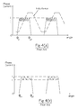
- the current is modulated inversely to the shape of the torque to keep the torque constant across the ⁇ angle. This is shown in Figure 9 .
- the ⁇ torque is quite low when only one phase is energised at a time, so the output from the machine has been reduced from the average torque of Figure 7 (approximately twice the ⁇ torque, depending on the actual wave shape) to the ⁇ torque.
- ⁇ torque in Figure 10 is shown as a straight line corresponding to an ideally flat or smooth torque
- the torque output for a given torque demand will fluctuate somewhat about the torque demand, between an upper and lower level of acceptable torque fluctuation, for example due to model inaccuracies or limited feedback gains.
- the torque output will be substantially flat or smooth, allowing for noise, inaccuracies or design constraints in the control process.
- phase conduction region Common to all these methods is the energisation of a phase such that it carries a current that varies with rotor position to compensate (as fully as possible or partially) for the nonlinear relationship between the phase current and torque generated by the phase.
- the resulting current waveform will have two peaks with a trough in between to reflect torque generation characteristics which produce a higher torque for a given current in a middle region of the phase conduction region.
- the current profile of the phase winding is altered in a detent region in the conduction region to ensure that the drive will stall at a point (or detent position) where the phase current is at or near its lowest value, thus minimising the associated losses in the drive system.
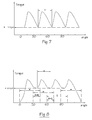
- Figure 12 shows a small dip introduced to the current profile of Figure 10 in a detent region DR to encourage stalling of the drive at a detent position within the detent region. This produces a corresponding dip in the torque, as shown.
- this torque waveform is applied to the tyre compliance, it will be seen from Figure 13 that the drive stalls at the torque dip, corresponding to the lowest current.
- the amount of torque dip needed will depend, inter alia, on the amount of compliance in the transmission of torque and the gearing between an electrical cycle of the machine and the load, but a typical value for a large industrial vehicle would be to introduce a torque dip of around 5% of the output torque.
- a notional current level 30 can be drawn in Figure 12 to divide the conduction region into five portions: two flanking portions A and E; a middle portion C in which the current is below the notional level; and two in-between portions B and D in which the current is above the notional level.
- Some benefit of stall current reduction can be achieved where the current (and hence torque) dip is introduced in the middle portion, where the current is lower than in the in-between portions. The benefit is higher, the lower the notional level.
- Optimum or near optimum stall current reduction may be achieved if the detent region is chosen to include the lowest point of the middle portion. By choosing the dip to occur in the middle portion, the current drawn by adjacent phases in some energisation schemes may also be reduced, depending on the positioning of the dip, the energisation scheme and the number of phases in the machine.
- the description above has illustrated the use of current profiling throughout the conduction angle. This can be implemented with the current controllers commonly used in drive systems.
- the invention can be put into effect by using other parameters to control the level of energisation in the machine, e.g., the drive may include a flux controller and the energisation may be controlled by monitoring the flux in the machine and controlling it to follow a predetermined profile.
- the invention in its various embodiments provides a torque control technique for electronically switched brushless machines of various types, and is particularly suited to switched reluctance machines. It allows close control of the thermal behaviour of the drive system.
- the disclosed embodiments illustrate a significant benefit, in that the additional control scheme can be incorporated into an existing control system with minimal modification. It will be apparent to the skilled person that various modifications and changes can be made to the specifically disclosed embodiments without departing from the invention. The invention is to be limited only by the scope of the following claims.
Landscapes
- Engineering & Computer Science (AREA)
- Power Engineering (AREA)
- Control Of Motors That Do Not Use Commutators (AREA)
- Control Of Electric Motors In General (AREA)
Abstract
Description
- This invention relates to the control of brushless electrical machines. The invention particularly, but not exclusively, relates to switched reluctance machines.
- The switched reluctance machine is a type of brushless electrical machine. It comprises a rotor, defining rotor poles, a stator, defining stator poles, and a set of windings arranged in relation to the stator poles to define one or more independently energisable phases. In a reluctance machine, energisation of one or more phase windings sets up magnetic flux in a circuit which includes the associated stator poles, urging the rotor into a position where the reluctance of the circuit is a minimum (and the inductance of the associated phase winding is a maximum). In motoring operation, timing the sequential energisation of the windings according to rotor position induces rotor movement. A general treatment of electrical drives which incorporate switched reluctance machines can be found in various textbooks, e.g. "Electronic Control of Switched Reluctance Machines" by TJE Miller, Newnes, 2001 which is incorporated herein by reference. More detail is provided in the paper 'The Characteristics, Design and Applications of Switched Reluctance Motors and Drives' by Stephenson and Blake, presented at the PCIM '93 Conference and Exhibition at Nurnberg, Germany, June 21-24, 1993 which is incorporated herein by reference. As is well known in the art, these machines can be operated as motors or generators by altering the timing of the application of the energisation to the phase windings.
- Unlike conventional induction and synchronous 'electromagnetic' machines, e.g., so-called brushless DC machines, in which the current is in stator coils and the field is produced by permanent magnets on the rotor, switched reluctance machines are purely 'magnetic' machines. The torque is produced solely by the magnetic field as the reluctance of the magnetic circuit changes. It follows that the methods of controlling the two types of machine are quite different, since the control is related to the method of torque production. In general, the control methods used for sinusoidally fed conventional machines are inappropriate for switched reluctance machines.
-
Figure 1 shows a typical switched reluctance machine in cross section. In this example, theferromagnetic stator 10 has sixstator poles 12. Theferromagnetic rotor 14 has fourrotor poles 16. Each stator pole carries acoil 18. The coils on diametrically opposite poles are connected in series to provide three phase windings. Only one phase winding is shown, for clarity. The control of the switched reluctance machine can be achieved in a variety of ways well known to the person skilled in the art. If information on the angular position of the rotor is available, e.g. from a position transducer, the excitation can be applied as a function of the position. Such machines are often referred to as "rotor position switched machines". - A typical switched reluctance drive is shown in
Figure 2 . In this example, themachine 36 corresponds to that shown inFigure 1 . The three phase windings, A, B and C, are switched in turn onto a DC supply V by a set of powerelectronic switches 48. The moments (i.e., the rotor positions) at which the switches operate are determined by thecontroller 38, which may be implemented either in hardware or in the software of a processing device such as a microcontroller or digital signal processor. The control signals are sent to the switches via adata bus 46. Closed loop current feedback is provided by sensing the phase currents using acurrent sensor 44 and feeding back a signal proportional to phase current which is compared to a demanded current iD. The control algorithms may include a proportional (P), proportional-plus-integral (P+I), time optimal, feedback linearised, proportional/integral/ derivative (PID) function, or one of many others as is well understood in the art. It is also common for an outer control loop of position or speed to be provided by feeding back a rotor position signal from aposition detector 40. - In operation, a signal corresponding to
current demand 42 is provided to the controller. This regulates the current in the windings, according to the particular control scheme adopted, to produce the desired output from the machine. - The performance of a switched reluctance machine depends, in part, on the accurate timing of phase energisation with respect to rotor position. Detection of rotor position is conventionally achieved by using a physical rotor position transducer (RPT) 40, shown schematically in
Figure 2 , such as a rotating toothed disk mounted on the machine rotor, which co-operates, for example, with an optical or magnetic sensor mounted on the stator. A pulse train indicative of rotor position relative to the stator is generated and supplied to the processing device, allowing accurate phase energisation. Alternative methods of position detection include the so-called "sensorless" methods, in which there is no physical position transducer and the position is deduced from measurements of one or more other parameters of the machine. - Since current in the windings is relatively easy to measure, closed-loop control of the machine is conventionally accomplished by monitoring and controlling the energising current in the windings. However, the desired output of the machine is usually torque, position or speed, and current has a highly non-linear relationship to all of these. The result is that current control techniques generally incur inaccuracies in the output, such as torque ripple, position error and/or speed error. Many current control schemes have been devised to address these shortcomings, as will be discussed further below.
- Many different power converter topologies are known, several of which are discussed in the Stephenson paper cited above. One of the most common configurations is shown for a single phase of a polyphase system in
Figure 3 , in which the phase winding 32 of the machine is connected in series with twoswitching devices busbars Energy recovery diodes switches capacitor 25, known as the "DC link capacitor", is connected across the DC link to source or sink any alternating component of the DC link current (i.e. the so-called "ripple current") which cannot be drawn from, or returned to, the supply. In practical terms, thecapacitor 25 may comprise several capacitors connected in series and/or parallel. Where parallel connection is used, some of the elements may be distributed throughout the converter. A polyphase system typically uses several "phase legs" ofFigure 3 connected in parallel to energise the phases of the electrical machine independently. - The phase inductance cycle of a switched reluctance machine is the period of the variation of inductance for the, or each, phase between common points in successive cycles (for example between inductance maxima when the rotor poles and the relevant respective stator poles are fully aligned). As explained in the Stephenson paper cited above, the maximum inductance region is centred around the rotor position where a pair of rotor poles are fully aligned with a pair of stator poles. Similarly, the minimum inductance region is centred around the position where the interpolar axis on the rotor is aligned with the stator pole axis, as shown in
Figure 1 . - At low speeds, switched reluctance systems generally operate in a current-controlled or "chopping" mode. A hysteresis current controller using "hard" chopping is often used, as explained in the Stephenson paper referred to above. This is illustrated in
Figure 4(a) where the current cycles between an upper hysteresis level Iu and a lower hysteresis level I1 in a conduction region of the phase in question, between the switch-on angle θon at which the phase is energised and the switch-off angle θoff at which energisation is removed. An alternative control regime is "soft" chopping in which only one switch is opened when the current reaches its upper level. The current then decays much more slowly through the winding, the second switch and one diode. This is shown inFigure 4(b) . Depending on the capability of the switches and the current controller, the width of the hysteresis band can be reduced until the current effectively becomes flat. If the angular speed of the rotor is slow, then the angle traversed by the rotor between switch-on and reaching the desired level is very small, so that the current waveshape appears to be rectangular, as will be discussed below. Other types of current controllers are well known in the art, for example those described inEP-A-0769844 , which is incorporated herein by reference, off-time controllers, constant frequency controllers, etc., and will not be further described here. - At higher speeds, switched reluctance systems typically operate in the "single-pulse" mode of energisation instead of the chopping mode. This is also explained in the Stephenson paper referred to above.
- Thus, systems generally use a chopping mode at low speeds and a single-pulse mode at higher speeds. The upper and lower chopping current levels are normally set to values above the expected peak current of the single pulse mode, so that these parameters do not interfere with single-pulse operation. It is known to set the upper current level to a value which would act as a "safety net" so that if a fault condition developed in the drive, the current would exceed this upper level and cause one or more switching devices to be opened, thereby limiting the current to a safe value.
- While motoring operation has been assumed in the above discussions, it is well-known that switched reluctance machines operate equally well in the generating mode, in which the current waveforms are generally mirror images of the motoring waveforms.
- Unlike some other types of electrical machine, the switched reluctance machine does not generally have a linear relationship between torque and current. The reasons for this are discussed in greater detail in the Miller book and the Stephenson paper cited above. The relationship is illustrated in
Figure 5 , where the so-called static torque for one phase of the three-phase machine ofFigure 1 is shown for a constant current applied over a rotor angle of 45°. For a current low in the working range of the machine (say below 10%), the torque would be almost rectangular. However, as the flux and current levels are raised, the magnetic properties of the iron carrying the flux become significantly non-linear and the shape of the torque becomes rounded. The shape of torque curve shown is typical for the rated current for the machine. - It will be realised by those skilled in the art that the current waveform shown in
Figure 5 is idealised, since the practical waveform would typically have some chopping ripple superimposed on the average current shown. -
Figure 6 shows the relationships between the torque curves of the different phases of the machine. For the machine with 6 stator poles and 4 rotor poles, the angular displacement of the curves (the so-called "ε angle") is 30°. The simplest method of providing continuous torque from the machine as it rotates is to switch on a phase when the torque curves cross and to switch it off and switch on the next phase after the ε angle has been traversed. This is illustrated inFigure 7 , again for a constant phase current. While this is a simple control regime to implement, it has the obvious drawback of producing a large torque ripple. The minimum torque available at any angle is called the ε torque and is shown inFigure 7 . The average torque produced over the ε angle will be somewhere between the peak torque and ε torque, depending on the exact shape of the curve. This method has another drawback in that each phase is only being used for one third of the phase period, so the utilisation of the stator and the electronic controller is poor. - To overcome these disadvantages, it is known to excite every phase whenever it has the potential to produce torque in the desired direction. For the 3-phase machine shown, this gives an excitation pattern of Phase A alone for 15°, followed by A+B for 15°, followed by Phase B alone for 15°, etc. It is illustrated in
Figure 8 (which neglects any mutual interaction between the phases). This pattern is known variously as phase overlap or as "1½ phases on". It will be seen that the ε torque has been effectively doubled (because two phases are now producing identical torque at the previous crossover point and the slopes of the torque curves have approximately the same magnitude). Because the peak torque is unchanged, the torque ripple is much smaller and the average torque has significantly increased. Each phase is now used for one half of the phase period, so the stator utilisation is increased. - Although this excitation regime is adopted for many drives, there are some applications where a smoother torque is required without undue penalty on the current rating for the devices used to control the currents.
- In one aspect of the invention there is provided a method of controlling a brushless electrical machine as defined in
claim 1. Further aspects of the invention provide a control system as defined inclaim 15 and a drive as defined inclaim 16. - In one embodiment, there is provided a method of controlling a brushless electrical machine to produce an output, wherein the output is torque or force. The method comprises energising a first phase of the machine in a conduction region between a switch-on point and a switch-off point. The machine is energised in response to an output demand to produce an output between an upper and a lower output limit, respectively higher or lower than the output demand, compensating for a non-linear relationship between the output of the brushless electrical machine and current in the first phase. The output between an upper and a lower output limit is produced in response to the output demand from a beginning of the conduction region to a detent region and from the detent region to an end of the conduction region. In the detent region, an output is produced at a detent level. The detent level is below the lower limit. In this way, stalling of the machine at a detent position within the detent region is favoured.
- Advantageously, by controlling the brushless electrical machine to produce an output between upper and lower output tolerance limits outside the detent region and to control the machine to drop the output below the lower tolerance limit, a detent region within which the machine is more likely to stall can be defined. This provides control over the stalling behaviour of the machine.
- In ideal conditions, the upper and lower output limits would be the same (equal to the output demand) so that the output would be ideally smooth or flat in the conduction region. In a real world context, the output fluctuations described above cannot be fully compensated so that the machine is controlled to produce an output at the output demand, which is substantially smooth or flat and varies between upper and lower limits due to uncompensated output fluctuations. For example, the upper and lower limits may be 5% on either side of the output demand, with flatter output potentially achievable, for example with upper and lower limits of 3% or even 1% or 2% on either side of the output demand (relative to the output demand). To achieve the substantially smooth or flat output any known output conditioning technique may be used, for example profiling of the current (or other controlled quantity, such as flux) to achieve the desired smoothness of the output. The control and/or profiling may be based on feed forward control based on the characteristics of the machine or feedback control based on a suitable feedback quantity, such as the output or variation of the output. A combination of feed forward and feedback control is equally possible. The various possible control schemes may employ sensorless forms of rotor position detection, or position detection using rotor position detector hardware. A combination of sensorless and hardware forms of rotor position detection is equally possible.
- In some embodiments, the detent level is less than 96% of the output demand. For example, the detent level may be 95%. Lower or higher values for the detent level are equally possible, although the detent effect is reduced for higher values, while lower levels may introduce undesirable torque ripple.
- In some embodiments, the method may comprise energising respective second and third phases together with the first phase. The second phase is energised together with the first phase for a first portion of the conduction region before the detent region and the third phase is energised together with the first phase for a second portion of the conduction region after the detent region to produce the output between the upper and lower limits. These embodiments may use the energisation scheme described above with reference to
Figure 8 to facilitate smoothing the output. - In some embodiments, as a result of controlling the machine to produce a substantially smooth output, the current drawn by the first phase for a constant output demand is above a notional level in a second and fourth portion of the conduction region. The second and fourth portions of the conduction region are located between first, third and fifth portions of the conduction region in which the current is below the notional level. Thus, the current profile (whether as result of direct current control or, for example, flux control) has two peaks with a trough in between. In some embodiments, the detent position is within the third portion, that is the trough portion between the two peaks of the current profile. In this way, the detent region is placed such that the detent position is within a region in which the current drawn by the first phase is relatively low. This means that the thermal load corresponding to the current drawn by the phase while stalling is reduced as compared to a situation in which the current drawn would be higher. The notional level may be less than the average of the maximum current in the conduction region of a first phase and the minimum current in the third portion of the conduction region of the first phase. The notional level may be less than the sum of 90% of the minimum current and 10% of the maximum current in the conduction region of the first phase. In some embodiments, the minimum of current in the third portion of the conduction region of the first phase occurs in the detent region. This results in the phase drawing minimum current (or close to minimum current) when stalling in the detent region.
- In some embodiments, the brushless electrical machine is coupled to a load by a compliant torque transmission arrangement. The compliance of the transmission arrangement means that the machine may move to a stall position within the detent region without movement of the load. In some embodiments, the brushless electrical machine is coupled to one or more traction wheels of a vehicle, for example a loader as discussed below.
- In some embodiments, the brushless electrical machine has more than one phase and the method comprises varying the output demand between at least two levels to cause the machine to stall at different detent positions, wherein each detent position is in a different phase. This allows the thermal load associated with the stall current to be shared between phases and thus can reduce heating of the machine in a stall condition. In particular, in some embodiments, the output demand is varied in response to detecting that the machine has stalled. The different phases may be mutually adjacent and for brushless electrical machines which have n phases, the output demand may be varied between n levels (to cause stall positions associated with each of the n phases to be visited).
- In some embodiments, the brushless electrical machine has a rotor, that is it is a rotating machine with a torque output. However, the present disclosure is equally applicable to embodiments in which the machine has a movable part arranged for linear motion relative to a stationary part and is thus a linear machine with an output of force.
- In some embodiments, the brushless electrical machine is a switched reluctance machine. In other embodiments, the brushless electrical machine may be a brushless DC machine or any other suitable type of brushless electrical machine.
- In some embodiments, the introduction of a detent region with an output at a detent level is made speed-dependent. To this end, for example, a speed of the machine is determined and an output produced in the detent region at the detent level if the speed is below a first value and at or above the lower level if the speed is above a second value. The second value may be the same as the first value and act as a threshold level. Alternatively, the second value could be larger than the first value, for example by implementing a gradual transition from the detent level to no output reduction at all as the speed increases from the first to the second value. This would reduce the risk of resonances being introduced in the machine/drive by the torque ripple associated with the periodic reduction in output to the detent level in the detent region.
- In other embodiments, there is provided a control system comprising means for controlling a brushless electrical machine in accordance with the methods and techniques described above. In yet further embodiments, there is provided a drive comprising a brushless electrical machine and a control system coupled to the brushless electrical machine. The control system comprises a processor configured to cause the control system to control the brushless electrical machine in accordance with the methods and techniques described above.
- The present invention can be put into practice in various ways, some of which will now be described by way of example with reference to the accompanying drawings in which:
-
Figure 1 shows a schematic axial cross-section of a switched reluctance machine; -
Figure 2 shows a schematic diagram of a switched reluctance machine drive system; -
Figure 3 shows part of a power converter circuit suitable for a switched reluctance machine; -
Figure 4(a) shows a chopping current waveform and its angular relationship to an inductance profile; -
Figure 4(b) shows a chopping current waveform incorporating freewheeling; -
Figure 5 shows torque and current waveforms for one phase of a machine; -
Figure 6 shows the waveforms ofFigure 5 overlaid for the other phases of the machine; -
Figure 7 shows a torque waveform produced by exciting one phase at a time; -
Figure 8 shows a torque waveform produced by overlapping phases; -
Figure 9 shows a phase current profile for producing smooth torque over a given rotor angle; -
Figure 10 shows a phase current profile which overlaps with another to give smooth torque; -
Figure 11 shows drive and load torques; -
Figure 12 shows torque and current waveforms; -
Figure 13 shows torque waveforms according to one aspect of the invention; and -
Figure 14 shows torque waveforms according to another aspect of the invention. - Some types of load are particularly susceptible to torque ripple produced by the prime mover and there are many techniques advocated for producing "smooth" torque, i.e. torque which has no significant variation with rotor position. Some of these techniques concentrate on mechanical solutions, e.g. modifying the profile of the rotor and/or stator poles, as disclosed in
EP 0930694 (Randall ). Other methods make the current a function of rotor angle, so that instead of being constant (as was shown inFigures 5 to 8 ), the magnitude of the current is varied during the conduction angle, as disclosed inUS 6922036 (Ehsani ). These latter techniques are generally described as "current profiling". - The current profiling can be achieved in a variety of ways. One of the simplest methods follows from
Figure 7 and uses one phase at a time. During the ε angle for any phase, the current is modulated inversely to the shape of the torque to keep the torque constant across the ε angle. This is shown inFigure 9 . In practice, however, there are three disadvantages to this approach. Firstly, it is not possible to apply or remove the current to the phase instantaneously. Secondly, as already discussed above with reference toFigure 7 , the ε torque is quite low when only one phase is energised at a time, so the output from the machine has been reduced from the average torque ofFigure 7 (approximately twice the ε torque, depending on the actual wave shape) to the ε torque. Thirdly, because the current is only present over a small part of the electrical cycle and because it has high peaks, it has a relatively high RMS value, leading to relatively high winding losses for the torque produced. - These disadvantages can be at least partly overcome by having two (or more) phases energised at some rotor angles, in the same manner as was illustrated in
Figure 8 above. The rising and falling edges of the phase currents are now profiled in such a way that the torque produced by the outgoing phase is coordinated with the torque produced by the incoming phase to give the constant value of torque required. This is illustrated for one phase inFigure 10 , where a constant, ripple-free torque can be achieved for a much smaller current than for the arrangement inFigure 9 . - While the ε torque in
Figure 10 is shown as a straight line corresponding to an ideally flat or smooth torque, in practice the torque output for a given torque demand will fluctuate somewhat about the torque demand, between an upper and lower level of acceptable torque fluctuation, for example due to model inaccuracies or limited feedback gains. As a result, in a real-world implementation, the torque output will be substantially flat or smooth, allowing for noise, inaccuracies or design constraints in the control process. - There are many different methods available for choosing the profile of the current to achieve this smooth torque, since there is no unique solution for the individual phase currents. For example: the paper "Torque ripple minimisation for variable reluctance motors", by Hung, JY in Mechatronics, Vol 4, No 8, 1994, pp 785 - 794 discusses a very simple method, which ignores the problem of saturation in the magnetic circuits; "Optimum commutation-current profile on torque linearization of switched reluctance motors" by Schramm, DS, Williams, BW & Green TC, in the Proceedings of the International Conference on Electrical Machines, 15-17 Sept 1992, Manchester, UK, Vol 2, pp 484 - 488 discloses a more complex method using look-up tables; and "A fuzzy iterative approach for determination of current waveform for switched reluctance motors using a torque sharing function at positive and negative torque production regions" by Gobbi, R & Sahoo, NC in the Proceedings of the 30th Annual Conference of the Industrial Electronics Society, 02-06 Nov 04, Busan, Korea, Vol 4, pp 3172 - 3177 invokes fuzzy logic methods to iterate towards a solution for the individual phase currents.
- Common to all these methods is the energisation of a phase such that it carries a current that varies with rotor position to compensate (as fully as possible or partially) for the nonlinear relationship between the phase current and torque generated by the phase. Generally, the resulting current waveform will have two peaks with a trough in between to reflect torque generation characteristics which produce a higher torque for a given current in a middle region of the phase conduction region.
- While the production of essentially ripple-free torque is often regarded as the best solution for applications requiring electrical drive systems, there is a class of applications where, surprisingly, this is not always the best overall solution. It is not uncommon that the torque required by the load exceeds that available from the drive, causing the system to stall. This can happen accidentally, or can be a deliberate event used to hold the load at a particular position. For example, if a hoist is being driven by a drive system and it is desired to hold the load at a particular height, then the load could be driven to a position and the torque reduced until the load is held at that position, thus avoiding the need to apply a brake. A further example is a traction drive for a vehicle which is scooping up loose material, e.g. a loader, where the vehicle is driven into a pile of material and held there while another operation is performed. This type of system is made more complicated by the presence of significant compliance in the rubber tyres which transmit the torque of the drive system to the ground. When the vehicle is moving along a smooth, constant gradient surface at steady speed, the compliance in the transmission of torque has no effect on the drive. However, if a stall condition is encountered, the tyres "wind up" as the drive continues to apply torque but the vehicle is prevented from moving.
- This is illustrated in
Figure 11 , where a smooth torque is supplied by the drive and winds up the compliance of the tyre until the tyre develops a torque equal to the drive torque, Point X. Typically, the gearing of a vehicle is such that the motor will have gone through many phase cycles, and possibly have turned several revolutions, in the wind-up process. It follows that a very small variation in the compliance (which could easily be caused by a change in ambient temperature, for example) could make a large difference to the particular position in the phase cycle where the rotor stops. Reference toFigure 9 or Figure 10 shows how the stall current could therefore easily change by a factor of 2 or 3. It follows that the associated losses in the winding and switching devices vary greatly, which leads to difficulty with the thermal management of the drive. - In order to control or influence the rotor position at which the drive stalls, the current profile of the phase winding is altered in a detent region in the conduction region to ensure that the drive will stall at a point (or detent position) where the phase current is at or near its lowest value, thus minimising the associated losses in the drive system.
Figure 12 shows a small dip introduced to the current profile ofFigure 10 in a detent region DR to encourage stalling of the drive at a detent position within the detent region. This produces a corresponding dip in the torque, as shown. When this torque waveform is applied to the tyre compliance, it will be seen fromFigure 13 that the drive stalls at the torque dip, corresponding to the lowest current. This has the beneficial effects of not only controlling the rotor angle at which the drive stalls, but ensuring that the stall point is in the detent region at the lowest point in the current profile. Further, if the drive is a 3-phase drive, inspection ofFigures 8 and12 will show that, since the dip is placed in the middle third of the current waveform, there is no current in the adjacent phases at that point. This further eases the thermal management of the drive. - This technique is counter-intuitive, since it re-introduces some torque ripple to the output of the machine, which would normally be considered something to avoid. However, it is seen from the description above that the controlled departure from the smooth torque of
Figure 9 or Figure 10 can be used to bring an overall benefit to the drive system by greatly easing the difficulties of thermal management under stall conditions. - The amount of torque dip needed will depend, inter alia, on the amount of compliance in the transmission of torque and the gearing between an electrical cycle of the machine and the load, but a typical value for a large industrial vehicle would be to introduce a torque dip of around 5% of the output torque.
- Conceptually, a notional
current level 30 can be drawn inFigure 12 to divide the conduction region into five portions: two flanking portions A and E; a middle portion C in which the current is below the notional level; and two in-between portions B and D in which the current is above the notional level. Some benefit of stall current reduction can be achieved where the current (and hence torque) dip is introduced in the middle portion, where the current is lower than in the in-between portions. The benefit is higher, the lower the notional level. Optimum or near optimum stall current reduction may be achieved if the detent region is chosen to include the lowest point of the middle portion. By choosing the dip to occur in the middle portion, the current drawn by adjacent phases in some energisation schemes may also be reduced, depending on the positioning of the dip, the energisation scheme and the number of phases in the machine. - It may be useful to make the introduction of a detent region speed-dependent, so that a detent region is only introduced when the drive is operating at low speeds or when the speed is approaching zero and a stall condition is likely. This would reduce any possibility of the ripple in the torque causing resonances in the drive train.
- While the technique described above can be used to greatly reduce the problem of thermal management in the stall condition, the loss is still concentrated in one phase winding and the phase leg of the converter supplying that phase. If the drive is stalled for a prolonged period, thermal limits may still be a consideration. A further aspect of the invention will now be described which can beneficially further improve the drive system. Inspection of
Figures 12 and13 will show that adjacent torque dips (and hence adjacent detent/stall positions) are associated with adjacent phases of the machine. It will be seen that, if the torque output is varied by a relatively small amount, the tyre torque line will intersect the drive torque profile on different dips. This is illustrated inFigure 14 , which shows an enlarged portion ofFigure 13 . - In
Figure 14 , the drive torque has been varied from its original value T to an increased value Ti and to a reduced value Tr. It will be seen that the load now causes the system to stall at new detent positions Xi and Xr, depending on the torque developed. The positions Xi, X and Xr each correspond to a position in the three phases of the machine used in this example. It will be clear that, for a system with a higher number of phases, a corresponding effect will be produced. In this way, the thermal load of the stall condition can be spread over some or all of the phases in the drive. For clarity,Figure 14 has shown an exaggerated view of the movement on the angular scale but in practice the movement is relatively small and would not produce adverse effects on the load. While a similar effect might be obtained with a system which does not use profiled phase currents, the embodiment described above enables a controlled movement from one phase to another and ensures that the points at which the drive settles all correspond to the lowest obtainable thermal load on the drive. - The description above has illustrated the use of current profiling throughout the conduction angle. This can be implemented with the current controllers commonly used in drive systems. The invention, however, can be put into effect by using other parameters to control the level of energisation in the machine, e.g., the drive may include a flux controller and the energisation may be controlled by monitoring the flux in the machine and controlling it to follow a predetermined profile.
- The description above has been made in terms of the example of a rotating machine having a rotor arranged for rotation relative to a stator to produce an output torque. The above description is equally applicable to linear machines having a moveable member linearly moveable relative to stationary member to produce an output force. It will be understood that in such a case reference to "rotor", "rotation", "torque", "angle", etc, can be replaced accordingly.
- The invention in its various embodiments provides a torque control technique for electronically switched brushless machines of various types, and is particularly suited to switched reluctance machines. It allows close control of the thermal behaviour of the drive system. The disclosed embodiments illustrate a significant benefit, in that the additional control scheme can be incorporated into an existing control system with minimal modification. It will be apparent to the skilled person that various modifications and changes can be made to the specifically disclosed embodiments without departing from the invention. The invention is to be limited only by the scope of the following claims.
Claims (15)
- A method of controlling a brushless electrical machine to produce an output, wherein the output is torque or force, the method comprising energising a first phase of the machine, in a conduction region between a switch-on point and a switch-off point, in response to an output demand, compensating for a nonlinear relationship between the output of the brushless electrical machine and current in the first phase to produce an output between an upper and a lower output limit, respectively higher and lower than the output demand, wherein the first phase is energised to produce the output between the upper and lower output limits from a beginning of the conduction region to a detent region and from the detent region to an end of the conduction region and to produce an output at a detent level in the detent region below the lower limit, thereby favouring stalling of the machine at a detent position within the detent region.
- A method as claimed in claim 1, wherein, for a constant output demand, the current drawn by the first phase is above a level in a second and fourth portion of the conduction region between, respectively, a first and third portion of the conduction region and the third portion and a fifth portion of the conduction region, the current being below the level in the first, third and fifth portion of the conduction region, and wherein the detent position is within the third portion of the conduction region.
- A method as claimed in claim 2, in which the level does not exceed the average of the maximum current in the conducting region and the minimum current in the third portion.
- A method as claimed in claim 2 or claim 3, in which the minimum current in the third portion occurs in the detent region.
- A method as claimed in any preceding claim, in which the detent level is less than 96% of the output demand
- A method as claimed in any preceding claim, the method further comprising energising respective second and third phases together with the first phase for a first portion of the conduction region before the detent region and for a second portion of the conduction region after the detent region to produce the output between the upper and lower limits.
- A method as claimed in any preceding claim, wherein the brushless electrical machine has more than one phase, each phase being energised as the first phase in any one of the preceding claims, the method comprising varying the output demand between at least two levels to cause the machine to stall at different detent positions, wherein each of the different detent positions is in a different phase.
- A method as claimed in claim 7, wherein the output demand is varied in response to detecting that the machine has stalled.
- A method as claimed in claim 7 or claim 8, in which the different phases are mutually adjacent.
- A method as claimed in claim 7 or claim 8, wherein the brushless electrical machine has n phases and the output demand is varied between n levels.
- A method as claimed in any preceding claim, wherein the method comprises determining a speed of the machine and producing an output in the detent region at the detent level if the speed is below a first value and producing an output in the detent region at a level at or above the lower level if the speed is above a second value, wherein the second value is equal to or greater than the first value.
- A method as claimed in any preceding claim, wherein the brushless electrical machine has an output of torque or force and is coupled to a load through a compliant transmission arrangement for transmitting the output to the load.
- A method as claimed in any one of the preceding claims, wherein the brushless electrical machine is coupled to one or more traction wheels of a vehicle.
- A method as claimed in any preceding claim, wherein the brushless electrical machine is a switched reluctance machine.
- A control system comprising means for controlling a brushless electrical machine in accordance with any one of claims 1 to 14.
Applications Claiming Priority (2)
| Application Number | Priority Date | Filing Date | Title |
|---|---|---|---|
| US201361769456P | 2013-02-26 | 2013-02-26 | |
| GBGB1303417.8A GB201303417D0 (en) | 2013-02-26 | 2013-02-26 | Control of a brushless electrical machine |
Publications (3)
| Publication Number | Publication Date |
|---|---|
| EP2770629A2 true EP2770629A2 (en) | 2014-08-27 |
| EP2770629A3 EP2770629A3 (en) | 2017-11-22 |
| EP2770629B1 EP2770629B1 (en) | 2020-03-11 |
Family
ID=48092132
Family Applications (1)
| Application Number | Title | Priority Date | Filing Date |
|---|---|---|---|
| EP14155108.5A Active EP2770629B1 (en) | 2013-02-26 | 2014-02-13 | Control of a Brushless Electrical Machine |
Country Status (6)
| Country | Link |
|---|---|
| US (1) | US9312801B2 (en) |
| EP (1) | EP2770629B1 (en) |
| JP (1) | JP2014166137A (en) |
| KR (1) | KR20140106454A (en) |
| CN (1) | CN104009683A (en) |
| GB (1) | GB201303417D0 (en) |
Families Citing this family (3)
| Publication number | Priority date | Publication date | Assignee | Title |
|---|---|---|---|---|
| US10122251B2 (en) | 2015-05-29 | 2018-11-06 | Com Dev Ltd. | Sequential actuator with sculpted active torque |
| CN106970527B (en) * | 2017-03-30 | 2020-04-10 | 奥克斯空调股份有限公司 | PID control engineering implementation method |
| US11215373B2 (en) * | 2018-01-08 | 2022-01-04 | Broan-Nutone Llc | System and method for integrated control of supply fan |
Citations (3)
| Publication number | Priority date | Publication date | Assignee | Title |
|---|---|---|---|---|
| EP0769844A1 (en) | 1995-10-18 | 1997-04-23 | Switched Reluctance Drives Limited | Current control circuit for a reluctance machine |
| EP0930694A2 (en) | 1998-01-20 | 1999-07-21 | Switched Reluctance Drives Limited | Noise reduction in reluctance machines |
| US6922036B1 (en) | 2000-11-30 | 2005-07-26 | The Texas A&M University System | Method and apparatus for reducing noise and vibration in switched reluctance motor drives |
Family Cites Families (12)
| Publication number | Priority date | Publication date | Assignee | Title |
|---|---|---|---|---|
| GB1460741A (en) * | 1973-09-10 | 1977-01-06 | Lan | |
| FR2614481B1 (en) * | 1987-02-13 | 1990-08-31 | Pk I | METHOD FOR CONTROLLING AN ASYNCHRONOUS MOTOR AND ELECTRIC DRIVE IMPLEMENTING THIS METHOD |
| JPH02206389A (en) * | 1989-01-31 | 1990-08-16 | Daikin Ind Ltd | Torque pulsation reducing method for reluctance motor |
| JPH0817586B2 (en) * | 1989-02-06 | 1996-02-21 | 株式会社日立製作所 | Digital controller |
| US5485047A (en) * | 1992-01-27 | 1996-01-16 | Kabushikigaisha Sekogiken | Reluctance-type motor and a rotor for a reluctance-type high-speed motor |
| EP0601189A4 (en) * | 1992-06-29 | 1995-01-11 | Sekoh Giken Kk | Reluctance motor capable of regenerative braking and direct current motor. |
| JPH07274570A (en) * | 1994-03-31 | 1995-10-20 | Aisin Seiki Co Ltd | Controller for switched reluctance motor |
| CA2151532C (en) * | 1994-07-25 | 1998-12-22 | Emerson Electric Co. | Auxiliary starting switched reluctance motor |
| US6891343B2 (en) * | 2003-03-14 | 2005-05-10 | Petersen Technology Corporation | Multiphase motors with single point sensing based commutation |
| CN1326315C (en) * | 2005-10-11 | 2007-07-11 | 中国矿业大学 | Output torque depulsation control method for switch reluctance servo motor |
| GB0618751D0 (en) * | 2006-09-22 | 2006-11-01 | Switched Reluctance Drives Ltd | Operating electrical machines from a DC link |
| CN102545743B (en) * | 2010-12-27 | 2014-08-06 | 北京中纺锐力机电有限公司 | Smooth control method for torque of switched reluctance motor |
-
2013
- 2013-02-26 GB GBGB1303417.8A patent/GB201303417D0/en not_active Ceased
-
2014
- 2014-02-13 EP EP14155108.5A patent/EP2770629B1/en active Active
- 2014-02-25 US US14/190,013 patent/US9312801B2/en not_active Expired - Fee Related
- 2014-02-25 JP JP2014034285A patent/JP2014166137A/en not_active Ceased
- 2014-02-26 CN CN201410067243.7A patent/CN104009683A/en active Pending
- 2014-02-26 KR KR1020140022936A patent/KR20140106454A/en not_active Application Discontinuation
Patent Citations (3)
| Publication number | Priority date | Publication date | Assignee | Title |
|---|---|---|---|---|
| EP0769844A1 (en) | 1995-10-18 | 1997-04-23 | Switched Reluctance Drives Limited | Current control circuit for a reluctance machine |
| EP0930694A2 (en) | 1998-01-20 | 1999-07-21 | Switched Reluctance Drives Limited | Noise reduction in reluctance machines |
| US6922036B1 (en) | 2000-11-30 | 2005-07-26 | The Texas A&M University System | Method and apparatus for reducing noise and vibration in switched reluctance motor drives |
Non-Patent Citations (5)
| Title |
|---|
| GOBBI, R; SAHOO, NC: "A fuzzy iterative approach for determination of current waveform for switched reluctance motors using a torque sharing function at positive and negative torque production regions", PROCEEDINGS OF THE 30TH ANNUAL CONFERENCE OF THE INDUSTRIAL ELECTRONICS SOCIETY, vol. 4, 2 November 2004 (2004-11-02), pages 3172 - 3177, XP010799479, DOI: doi:10.1109/IECON.2004.1432320 |
| HUNG, JY: "Torque ripple minimisation for variable reluctance motors", MECHATRONICS, vol. 4, no. 8, 1994, pages 785 - 794 |
| SCHRAMM, DS; WILLIAMS, BW; GREEN TC: "Optimum commutation-current profile on torque linearization of switched reluctance motor", PROCEEDINGS OF THE INTERNATIONAL CONFERENCE ON ELECTRICAL MACHINES, vol. 2, 15 September 1992 (1992-09-15), pages 484 - 488 |
| STEPHENSON; BLAKE: "The Characteristics, Design and Applications of Switched Reluctance Motors and Drives", PCIM '93 CONFERENCE AND EXHIBITION AT NURNBERG, 21 June 1993 (1993-06-21) |
| TJE MILLER: "Electronic Control of Switched Reluctance Machines", NEWNES, 2001 |
Also Published As
| Publication number | Publication date |
|---|---|
| EP2770629A3 (en) | 2017-11-22 |
| EP2770629B1 (en) | 2020-03-11 |
| US20140239862A1 (en) | 2014-08-28 |
| KR20140106454A (en) | 2014-09-03 |
| US9312801B2 (en) | 2016-04-12 |
| GB201303417D0 (en) | 2013-04-10 |
| JP2014166137A (en) | 2014-09-08 |
| CN104009683A (en) | 2014-08-27 |
Similar Documents
| Publication | Publication Date | Title |
|---|---|---|
| EP1959560B1 (en) | Control of an electrical machine | |
| Kjaer et al. | A new energy optimizing control strategy for switched reluctance motors | |
| DE69725231T2 (en) | Single phase permanent magnet motor | |
| Toliyat et al. | AC machines controlled as DC machines (Brushless DC machines/electronics) | |
| JP2010268675A (en) | Method and hardware system for driving stepper motor in feed-forward voltage mode | |
| CN106059406B (en) | A method of torque pulsation of brushless DC motor is inhibited based on delay hall signal | |
| EP3069442A1 (en) | Method and apparatus for control of switched reluctance motors | |
| Jinupun et al. | Direct torque control for sensorless switched reluctance motor drives | |
| EP2770629B1 (en) | Control of a Brushless Electrical Machine | |
| Lee | Torque ripple and switching power loss minimization with constant band hysteresis current controller for bldc motor | |
| JP2014166137A5 (en) | ||
| Song et al. | Direct torque control of switched reluctance motors | |
| Do et al. | Modeling, simulation and control of reluctance motor drives for high speed operation | |
| JP7199535B2 (en) | How to control a brushless permanent magnet motor | |
| KR101660509B1 (en) | Off Angle Control Method Reluctance Motor | |
| Hingmire et al. | Simulation and Analysis Studies of Speed Control of Brushless DC Motor Using Hall Sensors | |
| Husain | Switched reluctance machines | |
| Naitoh et al. | A current controller for a switched reluctance motor based on model reference adaptive control | |
| Sahoo et al. | A comparative study of Single Pulse Voltage and Hysteresis current control methods for switched reluctance motors | |
| Muthulakshmi et al. | Performance analysis of current controlled three phase switched reluctance motor | |
| Kumar | Enhancement of Dynamic Performance of Brush-Less DC Motor Drive | |
| Oh et al. | A novel control scheme for low cost SRM drive | |
| Ishikawa et al. | Novel speed control system with flat torque control for switched reluctance motor drives | |
| TAQUI et al. | Fault Tolerant 8/6 SRM Integrated with Current Source Converter for Power Factor Correction | |
| Mondal et al. | Evaluation of a novel analog based closed-loop sensorless controller for switched reluctance motor drive |
Legal Events
| Date | Code | Title | Description |
|---|---|---|---|
| PUAI | Public reference made under article 153(3) epc to a published international application that has entered the european phase |
Free format text: ORIGINAL CODE: 0009012 |
|
| 17P | Request for examination filed |
Effective date: 20140213 |
|
| AK | Designated contracting states |
Kind code of ref document: A2 Designated state(s): AL AT BE BG CH CY CZ DE DK EE ES FI FR GB GR HR HU IE IS IT LI LT LU LV MC MK MT NL NO PL PT RO RS SE SI SK SM TR |
|
| AX | Request for extension of the european patent |
Extension state: BA ME |
|
| PUAL | Search report despatched |
Free format text: ORIGINAL CODE: 0009013 |
|
| AK | Designated contracting states |
Kind code of ref document: A3 Designated state(s): AL AT BE BG CH CY CZ DE DK EE ES FI FR GB GR HR HU IE IS IT LI LT LU LV MC MK MT NL NO PL PT RO RS SE SI SK SM TR |
|
| AX | Request for extension of the european patent |
Extension state: BA ME |
|
| RIC1 | Information provided on ipc code assigned before grant |
Ipc: H02P 7/298 20160101AFI20171019BHEP |
|
| STAA | Information on the status of an ep patent application or granted ep patent |
Free format text: STATUS: REQUEST FOR EXAMINATION WAS MADE |
|
| R17P | Request for examination filed (corrected) |
Effective date: 20180510 |
|
| RBV | Designated contracting states (corrected) |
Designated state(s): AL AT BE BG CH CY CZ DE DK EE ES FI FR GB GR HR HU IE IS IT LI LT LU LV MC MK MT NL NO PL PT RO RS SE SI SK SM TR |
|
| GRAP | Despatch of communication of intention to grant a patent |
Free format text: ORIGINAL CODE: EPIDOSNIGR1 |
|
| STAA | Information on the status of an ep patent application or granted ep patent |
Free format text: STATUS: GRANT OF PATENT IS INTENDED |
|
| INTG | Intention to grant announced |
Effective date: 20191002 |
|
| GRAS | Grant fee paid |
Free format text: ORIGINAL CODE: EPIDOSNIGR3 |
|
| GRAA | (expected) grant |
Free format text: ORIGINAL CODE: 0009210 |
|
| STAA | Information on the status of an ep patent application or granted ep patent |
Free format text: STATUS: THE PATENT HAS BEEN GRANTED |
|
| AK | Designated contracting states |
Kind code of ref document: B1 Designated state(s): AL AT BE BG CH CY CZ DE DK EE ES FI FR GB GR HR HU IE IS IT LI LT LU LV MC MK MT NL NO PL PT RO RS SE SI SK SM TR |
|
| REG | Reference to a national code |
Ref country code: GB Ref legal event code: FG4D |
|
| REG | Reference to a national code |
Ref country code: CH Ref legal event code: EP |
|
| REG | Reference to a national code |
Ref country code: AT Ref legal event code: REF Ref document number: 1244413 Country of ref document: AT Kind code of ref document: T Effective date: 20200315 |
|
| REG | Reference to a national code |
Ref country code: IE Ref legal event code: FG4D |
|
| REG | Reference to a national code |
Ref country code: DE Ref legal event code: R096 Ref document number: 602014062065 Country of ref document: DE |
|
| PG25 | Lapsed in a contracting state [announced via postgrant information from national office to epo] |
Ref country code: FI Free format text: LAPSE BECAUSE OF FAILURE TO SUBMIT A TRANSLATION OF THE DESCRIPTION OR TO PAY THE FEE WITHIN THE PRESCRIBED TIME-LIMIT Effective date: 20200311 Ref country code: RS Free format text: LAPSE BECAUSE OF FAILURE TO SUBMIT A TRANSLATION OF THE DESCRIPTION OR TO PAY THE FEE WITHIN THE PRESCRIBED TIME-LIMIT Effective date: 20200311 Ref country code: NO Free format text: LAPSE BECAUSE OF FAILURE TO SUBMIT A TRANSLATION OF THE DESCRIPTION OR TO PAY THE FEE WITHIN THE PRESCRIBED TIME-LIMIT Effective date: 20200611 |
|
| REG | Reference to a national code |
Ref country code: NL Ref legal event code: MP Effective date: 20200311 |
|
| PG25 | Lapsed in a contracting state [announced via postgrant information from national office to epo] |
Ref country code: BG Free format text: LAPSE BECAUSE OF FAILURE TO SUBMIT A TRANSLATION OF THE DESCRIPTION OR TO PAY THE FEE WITHIN THE PRESCRIBED TIME-LIMIT Effective date: 20200611 Ref country code: HR Free format text: LAPSE BECAUSE OF FAILURE TO SUBMIT A TRANSLATION OF THE DESCRIPTION OR TO PAY THE FEE WITHIN THE PRESCRIBED TIME-LIMIT Effective date: 20200311 Ref country code: GR Free format text: LAPSE BECAUSE OF FAILURE TO SUBMIT A TRANSLATION OF THE DESCRIPTION OR TO PAY THE FEE WITHIN THE PRESCRIBED TIME-LIMIT Effective date: 20200612 Ref country code: LV Free format text: LAPSE BECAUSE OF FAILURE TO SUBMIT A TRANSLATION OF THE DESCRIPTION OR TO PAY THE FEE WITHIN THE PRESCRIBED TIME-LIMIT Effective date: 20200311 Ref country code: SE Free format text: LAPSE BECAUSE OF FAILURE TO SUBMIT A TRANSLATION OF THE DESCRIPTION OR TO PAY THE FEE WITHIN THE PRESCRIBED TIME-LIMIT Effective date: 20200311 |
|
| REG | Reference to a national code |
Ref country code: LT Ref legal event code: MG4D |
|
| PG25 | Lapsed in a contracting state [announced via postgrant information from national office to epo] |
Ref country code: NL Free format text: LAPSE BECAUSE OF FAILURE TO SUBMIT A TRANSLATION OF THE DESCRIPTION OR TO PAY THE FEE WITHIN THE PRESCRIBED TIME-LIMIT Effective date: 20200311 |
|
| PG25 | Lapsed in a contracting state [announced via postgrant information from national office to epo] |
Ref country code: SM Free format text: LAPSE BECAUSE OF FAILURE TO SUBMIT A TRANSLATION OF THE DESCRIPTION OR TO PAY THE FEE WITHIN THE PRESCRIBED TIME-LIMIT Effective date: 20200311 Ref country code: SK Free format text: LAPSE BECAUSE OF FAILURE TO SUBMIT A TRANSLATION OF THE DESCRIPTION OR TO PAY THE FEE WITHIN THE PRESCRIBED TIME-LIMIT Effective date: 20200311 Ref country code: PT Free format text: LAPSE BECAUSE OF FAILURE TO SUBMIT A TRANSLATION OF THE DESCRIPTION OR TO PAY THE FEE WITHIN THE PRESCRIBED TIME-LIMIT Effective date: 20200805 Ref country code: CZ Free format text: LAPSE BECAUSE OF FAILURE TO SUBMIT A TRANSLATION OF THE DESCRIPTION OR TO PAY THE FEE WITHIN THE PRESCRIBED TIME-LIMIT Effective date: 20200311 Ref country code: RO Free format text: LAPSE BECAUSE OF FAILURE TO SUBMIT A TRANSLATION OF THE DESCRIPTION OR TO PAY THE FEE WITHIN THE PRESCRIBED TIME-LIMIT Effective date: 20200311 Ref country code: IS Free format text: LAPSE BECAUSE OF FAILURE TO SUBMIT A TRANSLATION OF THE DESCRIPTION OR TO PAY THE FEE WITHIN THE PRESCRIBED TIME-LIMIT Effective date: 20200711 Ref country code: LT Free format text: LAPSE BECAUSE OF FAILURE TO SUBMIT A TRANSLATION OF THE DESCRIPTION OR TO PAY THE FEE WITHIN THE PRESCRIBED TIME-LIMIT Effective date: 20200311 Ref country code: EE Free format text: LAPSE BECAUSE OF FAILURE TO SUBMIT A TRANSLATION OF THE DESCRIPTION OR TO PAY THE FEE WITHIN THE PRESCRIBED TIME-LIMIT Effective date: 20200311 |
|
| REG | Reference to a national code |
Ref country code: AT Ref legal event code: MK05 Ref document number: 1244413 Country of ref document: AT Kind code of ref document: T Effective date: 20200311 |
|
| REG | Reference to a national code |
Ref country code: DE Ref legal event code: R097 Ref document number: 602014062065 Country of ref document: DE |
|
| PLBE | No opposition filed within time limit |
Free format text: ORIGINAL CODE: 0009261 |
|
| STAA | Information on the status of an ep patent application or granted ep patent |
Free format text: STATUS: NO OPPOSITION FILED WITHIN TIME LIMIT |
|
| PG25 | Lapsed in a contracting state [announced via postgrant information from national office to epo] |
Ref country code: IT Free format text: LAPSE BECAUSE OF FAILURE TO SUBMIT A TRANSLATION OF THE DESCRIPTION OR TO PAY THE FEE WITHIN THE PRESCRIBED TIME-LIMIT Effective date: 20200311 Ref country code: AT Free format text: LAPSE BECAUSE OF FAILURE TO SUBMIT A TRANSLATION OF THE DESCRIPTION OR TO PAY THE FEE WITHIN THE PRESCRIBED TIME-LIMIT Effective date: 20200311 Ref country code: DK Free format text: LAPSE BECAUSE OF FAILURE TO SUBMIT A TRANSLATION OF THE DESCRIPTION OR TO PAY THE FEE WITHIN THE PRESCRIBED TIME-LIMIT Effective date: 20200311 Ref country code: ES Free format text: LAPSE BECAUSE OF FAILURE TO SUBMIT A TRANSLATION OF THE DESCRIPTION OR TO PAY THE FEE WITHIN THE PRESCRIBED TIME-LIMIT Effective date: 20200311 |
|
| 26N | No opposition filed |
Effective date: 20201214 |
|
| PG25 | Lapsed in a contracting state [announced via postgrant information from national office to epo] |
Ref country code: PL Free format text: LAPSE BECAUSE OF FAILURE TO SUBMIT A TRANSLATION OF THE DESCRIPTION OR TO PAY THE FEE WITHIN THE PRESCRIBED TIME-LIMIT Effective date: 20200311 Ref country code: SI Free format text: LAPSE BECAUSE OF FAILURE TO SUBMIT A TRANSLATION OF THE DESCRIPTION OR TO PAY THE FEE WITHIN THE PRESCRIBED TIME-LIMIT Effective date: 20200311 |
|
| PG25 | Lapsed in a contracting state [announced via postgrant information from national office to epo] |
Ref country code: MC Free format text: LAPSE BECAUSE OF FAILURE TO SUBMIT A TRANSLATION OF THE DESCRIPTION OR TO PAY THE FEE WITHIN THE PRESCRIBED TIME-LIMIT Effective date: 20200311 |
|
| REG | Reference to a national code |
Ref country code: BE Ref legal event code: MM Effective date: 20210228 |
|
| PG25 | Lapsed in a contracting state [announced via postgrant information from national office to epo] |
Ref country code: LU Free format text: LAPSE BECAUSE OF NON-PAYMENT OF DUE FEES Effective date: 20210213 Ref country code: LI Free format text: LAPSE BECAUSE OF NON-PAYMENT OF DUE FEES Effective date: 20210228 Ref country code: CH Free format text: LAPSE BECAUSE OF NON-PAYMENT OF DUE FEES Effective date: 20210228 |
|
| PG25 | Lapsed in a contracting state [announced via postgrant information from national office to epo] |
Ref country code: IE Free format text: LAPSE BECAUSE OF NON-PAYMENT OF DUE FEES Effective date: 20210213 |
|
| PGFP | Annual fee paid to national office [announced via postgrant information from national office to epo] |
Ref country code: GB Payment date: 20220131 Year of fee payment: 9 Ref country code: DE Payment date: 20220228 Year of fee payment: 9 |
|
| PGFP | Annual fee paid to national office [announced via postgrant information from national office to epo] |
Ref country code: FR Payment date: 20220218 Year of fee payment: 9 |
|
| PG25 | Lapsed in a contracting state [announced via postgrant information from national office to epo] |
Ref country code: BE Free format text: LAPSE BECAUSE OF NON-PAYMENT OF DUE FEES Effective date: 20210228 |
|
| PG25 | Lapsed in a contracting state [announced via postgrant information from national office to epo] |
Ref country code: HU Free format text: LAPSE BECAUSE OF FAILURE TO SUBMIT A TRANSLATION OF THE DESCRIPTION OR TO PAY THE FEE WITHIN THE PRESCRIBED TIME-LIMIT; INVALID AB INITIO Effective date: 20140213 |
|
| PG25 | Lapsed in a contracting state [announced via postgrant information from national office to epo] |
Ref country code: CY Free format text: LAPSE BECAUSE OF FAILURE TO SUBMIT A TRANSLATION OF THE DESCRIPTION OR TO PAY THE FEE WITHIN THE PRESCRIBED TIME-LIMIT Effective date: 20200311 |
|
| REG | Reference to a national code |
Ref country code: DE Ref legal event code: R119 Ref document number: 602014062065 Country of ref document: DE |
|
| GBPC | Gb: european patent ceased through non-payment of renewal fee |
Effective date: 20230213 |
|
| PG25 | Lapsed in a contracting state [announced via postgrant information from national office to epo] |
Ref country code: GB Free format text: LAPSE BECAUSE OF NON-PAYMENT OF DUE FEES Effective date: 20230213 |
|
| PG25 | Lapsed in a contracting state [announced via postgrant information from national office to epo] |
Ref country code: GB Free format text: LAPSE BECAUSE OF NON-PAYMENT OF DUE FEES Effective date: 20230213 Ref country code: FR Free format text: LAPSE BECAUSE OF NON-PAYMENT OF DUE FEES Effective date: 20230228 Ref country code: DE Free format text: LAPSE BECAUSE OF NON-PAYMENT OF DUE FEES Effective date: 20230901 |
|
| PG25 | Lapsed in a contracting state [announced via postgrant information from national office to epo] |
Ref country code: MK Free format text: LAPSE BECAUSE OF FAILURE TO SUBMIT A TRANSLATION OF THE DESCRIPTION OR TO PAY THE FEE WITHIN THE PRESCRIBED TIME-LIMIT Effective date: 20200311 |