EP2770607A1 - Electricity storage device control system - Google Patents
Electricity storage device control system Download PDFInfo
- Publication number
- EP2770607A1 EP2770607A1 EP20110874140 EP11874140A EP2770607A1 EP 2770607 A1 EP2770607 A1 EP 2770607A1 EP 20110874140 EP20110874140 EP 20110874140 EP 11874140 A EP11874140 A EP 11874140A EP 2770607 A1 EP2770607 A1 EP 2770607A1
- Authority
- EP
- European Patent Office
- Prior art keywords
- electrical storage
- charging
- discharging
- state
- control part
- Prior art date
- Legal status (The legal status is an assumption and is not a legal conclusion. Google has not performed a legal analysis and makes no representation as to the accuracy of the status listed.)
- Granted
Links
Images





Classifications
-
- H—ELECTRICITY
- H02—GENERATION; CONVERSION OR DISTRIBUTION OF ELECTRIC POWER
- H02J—ELECTRIC POWER NETWORKS; CIRCUIT ARRANGEMENTS OR SYSTEMS FOR SUPPLYING OR DISTRIBUTING ELECTRIC POWER; SYSTEMS FOR STORING ELECTRIC ENERGY
- H02J7/00—Circuit arrangements for charging or discharging batteries or for supplying loads from batteries
- H02J7/50—Circuit arrangements for charging or discharging batteries or for supplying loads from batteries acting upon multiple batteries simultaneously or sequentially
- H02J7/52—Circuit arrangements for charging or discharging batteries or for supplying loads from batteries acting upon multiple batteries simultaneously or sequentially for charge balancing, e.g. equalisation of charge between batteries
-
- H—ELECTRICITY
- H01—ELECTRIC ELEMENTS
- H01M—PROCESSES OR MEANS, e.g. BATTERIES, FOR THE DIRECT CONVERSION OF CHEMICAL ENERGY INTO ELECTRICAL ENERGY
- H01M10/00—Secondary cells; Manufacture thereof
- H01M10/42—Methods or arrangements for servicing or maintenance of secondary cells or secondary half-cells
- H01M10/44—Methods for charging or discharging
- H01M10/441—Methods for charging or discharging for several batteries or cells simultaneously or sequentially
-
- H—ELECTRICITY
- H02—GENERATION; CONVERSION OR DISTRIBUTION OF ELECTRIC POWER
- H02J—ELECTRIC POWER NETWORKS; CIRCUIT ARRANGEMENTS OR SYSTEMS FOR SUPPLYING OR DISTRIBUTING ELECTRIC POWER; SYSTEMS FOR STORING ELECTRIC ENERGY
- H02J4/00—Circuit arrangements for mains or distribution networks not specified as AC or DC; Circuit arrangements for mains or distribution networks combining AC and DC sections or sub-networks
- H02J4/20—Networks integrating separated AC and DC power sections
- H02J4/25—Networks integrating separated AC and DC power sections for transfer of electric power between AC and DC networks, e.g. for supplying the DC section within a load from an AC mains system
-
- H—ELECTRICITY
- H02—GENERATION; CONVERSION OR DISTRIBUTION OF ELECTRIC POWER
- H02J—ELECTRIC POWER NETWORKS; CIRCUIT ARRANGEMENTS OR SYSTEMS FOR SUPPLYING OR DISTRIBUTING ELECTRIC POWER; SYSTEMS FOR STORING ELECTRIC ENERGY
- H02J7/00—Circuit arrangements for charging or discharging batteries or for supplying loads from batteries
- H02J7/60—Circuit arrangements for charging or discharging batteries or for supplying loads from batteries including safety or protection arrangements
- H02J7/65—Circuit arrangements for charging or discharging batteries or for supplying loads from batteries including safety or protection arrangements against overtemperature
-
- H—ELECTRICITY
- H02—GENERATION; CONVERSION OR DISTRIBUTION OF ELECTRIC POWER
- H02J—ELECTRIC POWER NETWORKS; CIRCUIT ARRANGEMENTS OR SYSTEMS FOR SUPPLYING OR DISTRIBUTING ELECTRIC POWER; SYSTEMS FOR STORING ELECTRIC ENERGY
- H02J7/00—Circuit arrangements for charging or discharging batteries or for supplying loads from batteries
- H02J7/60—Circuit arrangements for charging or discharging batteries or for supplying loads from batteries including safety or protection arrangements
- H02J7/663—Circuit arrangements for charging or discharging batteries or for supplying loads from batteries including safety or protection arrangements using battery or load disconnect circuits
- H02J7/667—Circuit arrangements for charging or discharging batteries or for supplying loads from batteries including safety or protection arrangements using battery or load disconnect circuits disconnection of loads if battery is not under charge, e.g. in vehicle if engine is not running
-
- H—ELECTRICITY
- H02—GENERATION; CONVERSION OR DISTRIBUTION OF ELECTRIC POWER
- H02J—ELECTRIC POWER NETWORKS; CIRCUIT ARRANGEMENTS OR SYSTEMS FOR SUPPLYING OR DISTRIBUTING ELECTRIC POWER; SYSTEMS FOR STORING ELECTRIC ENERGY
- H02J7/00—Circuit arrangements for charging or discharging batteries or for supplying loads from batteries
- H02J7/90—Regulation of charging or discharging current or voltage
- H02J7/971—Regulation of charging or discharging current or voltage the charge cycle being controlled or terminated in response to non-electric parameters
- H02J7/975—Regulation of charging or discharging current or voltage the charge cycle being controlled or terminated in response to non-electric parameters in response to temperature
- H02J7/977—Regulation of charging or discharging current or voltage the charge cycle being controlled or terminated in response to non-electric parameters in response to temperature of the battery
-
- Y—GENERAL TAGGING OF NEW TECHNOLOGICAL DEVELOPMENTS; GENERAL TAGGING OF CROSS-SECTIONAL TECHNOLOGIES SPANNING OVER SEVERAL SECTIONS OF THE IPC; TECHNICAL SUBJECTS COVERED BY FORMER USPC CROSS-REFERENCE ART COLLECTIONS [XRACs] AND DIGESTS
- Y02—TECHNOLOGIES OR APPLICATIONS FOR MITIGATION OR ADAPTATION AGAINST CLIMATE CHANGE
- Y02E—REDUCTION OF GREENHOUSE GAS [GHG] EMISSIONS, RELATED TO ENERGY GENERATION, TRANSMISSION OR DISTRIBUTION
- Y02E60/00—Enabling technologies; Technologies with a potential or indirect contribution to GHG emissions mitigation
- Y02E60/10—Energy storage using batteries
Definitions
- the present invention relates to an electrical storage battery management system for performing control during charging/discharging operations of an electrical storage device that includes electrical storage cells such as lithium ion batteries.
- An electrical storage device used as a power source for various electronic and electric devices is generally configured by series-parallel connection of a plurality of secondary batteries.
- the electrical storage device When used as a power source, the electrical storage device is connected to an electronic or electric device and discharges electricity. In the case of charging the electrical storage device, the electrical storage device is connected to a power supply system.
- Patent Document 1 is an example of a prior art document relating to lithium ion batteries.
- Patent Document 2 is an example of a prior art document relating to electrical storage devices.
- a lithium ion battery according to Patent Document 1 is capable of preventing overcharging/overdischarging and controlling battery temperature without retaining space for heat dissipation.
- An electrical storage device according to Patent Document 2 is capable of quick charging with high current and thereby reliably cutting the charging current off when the battery temperature becomes high.
- an object of the present invention to provide an electrical storage device management system that allows an electrical storage device to obtain high input/output currents continuously over a long period of time when charging/discharging.
- the electrical storage device management system includes a plurality of rows of electrical storage systems, a plurality of chargeable/dischargeable electrical storage cells constituting each of the electrical storage systems, a plurality of switching parts provided in correspondence with the electrical storage systems, a plurality of temperature sensors provided in correspondence with the electrical storage cells and configured to detect temperatures of the corresponding electrical storage cells, and a control part connected to the switching parts and the temperature sensors.
- the control part has set therein a first threshold temperature.
- the control part is configured to (A) monitor the temperatures of the electrical storage cells on the basis of temperature information transmitted from the temperature sensors, and when a result of the operation (A) indicates that the temperature of one of the electrical storage cells has reached the first threshold temperature in one of the electrical storage systems that is in a charging/discharging operating state, (B) perform system switching in which the switching part that is disposed in correspondence with the electrical storage system that includes the electrical storage cell is controlled, and the electrical storage system is switched from the charging/discharging operating state to a non-charging/discharging state, and (C) perform system switching in which one of the switching parts that is disposed in correspondence with one of the electrical storage systems that is in the non-charging/discharging state is controlled, and the electrical storage system is switched from the non-charging/discharging state to the charging/discharging operating state.
- the electrical storage device management system includes a plurality of rows of electrical storage systems, a plurality of chargeable/dischargeable electrical storage cells constituting each of the electrical storage systems, a plurality of switching parts provided in correspondence with the electrical storage systems, a plurality of temperature sensors provided in correspondence with the electrical storage cells and configured to detect temperatures of the corresponding electrical storage cells, and a control part connected to the switching parts and the temperature sensors.
- the control part has set therein a first threshold temperature.
- the control part is configured to (A) monitor the temperatures of the electrical storage cells on the basis of temperature information transmitted from the temperature sensors, and when a result of the operation (A) indicates that the temperature of one of the electrical storage cells has reached the first threshold temperature in one of the electrical storage systems that is in a charging/discharging operating state, (B) perform system switching in which the switching part that is disposed in correspondence with the electrical storage system that includes the electrical storage cell is controlled, and the electrical storage system is switched from the charging/discharging operating state to a non-charging/discharging state, and (C) perform system switching in which one of the switching parts that is disposed in correspondence with one of the electrical storage systems that is in the non-charging/discharging state is controlled, and the electrical storage system is switched from the non-charging/discharging state to the charging/discharging operating state.
- an electrical storage device management system that allows an electrical storage device to obtain high input/output currents continuously over a long period of time when charging/discharging.
- an electrical storage device is configured by a plurality of rows of electrical storage systems.
- Each of the electrical storage systems is configured by a plurality of chargeable/dischargeable electrical storage cells.
- the electrical storage systems are each provided with a switching part.
- not all of the electrical storage systems perform charging/discharging operations during charging/discharging processing, and some of the electrical storage systems are in a non-charging/discharging state in which they do not perform charging/discharging operations.
- the electrical storage cells generate heat according to the current value during charging/discharging, and the electrical storage device management system according to the present invention monitors the temperatures of the respective electrical storage cells. If the temperature of one of the electrical storage cells becomes high, the electrical storage device management system controls the corresponding switching part so as to disconnect an electrical storage system that includes the high-temperature electrical storage cell (hereinafter, referred to as an electrical storage system A) from the charging/discharging processing.
- an electrical storage system A an electrical storage system that includes the high-temperature electrical storage cell
- the electrical storage device management system also selects an arbitrary electrical storage system from among the electrical storage systems that are in the above non-charging/discharging state and controls the switching part connected to the selected electrical storage system. Under the control of the switching part, the selected electrical storage system (referred to as an "electrical storage system B") is switched from the non-charging/discharging state to a charging/discharging operating state, and the electrical storage system B performs charging/discharging operations, instead of the electrical storage system A.
- an electrical storage system B is switched from the non-charging/discharging state to a charging/discharging operating state, and the electrical storage system B performs charging/discharging operations, instead of the electrical storage system A.
- the electrical storage cells constituting the electrical storage systems are all storage batteries such as lithium ion batteries. In the description of the present embodiment, electrical storage cells are referred as "storage batteries.”
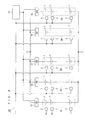
- FIG. 1 is a diagram illustrating a configuration of an electrical storage device management system 100 according to the present embodiment.
- the configuration excluding a control part 10 can be regarded as an electrical storage device.
- the electrical storage device management system 100 includes the electrical storage device and the control part 10, which is for monitoring and controlling the electrical storage device.
- portions of the electrical storage device that are indicated by dashed lines in FIG. 1 are connected to a load such as an electronic or electric device via a converter or the like, so that the electrical storage device functions as a power source for the load.
- a load such as an electronic or electric device
- the same portions indicated by dashed lines are also used in the case of charging via a converter or the like.
- the electrical storage device includes a plurality of rows of electrical storage systems G1, G2, G3, ..., GN-1, and GN.
- the electrical storage systems G1, G2, G3, ..., GN-1, and GN are each configured by a plurality of chargeable/dischargeable storage batteries 1.
- the storage batteries 1 are chargeable/dischargeable secondary batteries and may be lithium ion batteries, for example.
- the electrical storage systems G1, G2, G3, ..., GN-1, and GN are each configured by a plurality of series-connected storage batteries 1.
- the electrical storage systems G1, G2, G3, ...,GN-1, and GN are respectively provided with switching parts S1, S2, S3, ..., SN-1, and SN as shown in FIG. 1 .
- the switching part S1 is connected to an electrical storage battery 1 that is located at one end of the electrical storage system G1.
- the switching part S2 is connected to an electrical storage battery 1 that is located at one end of the electrical storage system G2.
- the switching part S3 is connected to an electrical storage battery 1 that is located at one end of the electrical storage system G3.
- the switching part SN-1 is connected to an electrical storage battery 1 that is located at one end of the electrical storage system GN-1.
- the switching part SN is connected to an electrical storage battery 1 that is located at one end of the electrical storage system GN.
- the current input/output ends of the switching parts S1 to SN-1 are commonly connected to one another by wiring (see one side of the portions indicated by dashed lines).
- the switching parts S1, S2, S3, ..., SN-1, and SN are connected to the control part 10 so as to be capable of transmitting and receiving data and signals, for example.
- the switching parts S1, S2, S3, ..., SN-1, and SN are turned on or off under the control of the control part 10.
- the electrical storage systems G1, G2, G3, ...,GN-1, and GN connected to the switching parts S1, S2, S3, ..., SN-1, and SN are chargeable/dischargeable (i.e., they are in the charging/discharging operating state).
- the switching parts S1, S2, S3, ..., SN-1, and SN are in the OFF state, the electrical storage systems G1, G2, G3, ...,GN-1, and GN connected to the switching parts S1, S2, S3, ..., SN-1, and SN are not chargeable/dischargeable (i.e., they are in the non-charging/discharging state).
- the electrical storage device management system 100 also includes a plurality of temperature sensors 2 as shown in FIG. 1 .
- Each of the temperature sensors 2 is disposed in correspondence with and in the vicinity of one of the storage batteries 1.
- the temperature sensors 2 are connected to the control part 10 so as to be capable of transmitting and receiving data and signals, for example. Each of the temperature sensors 2 detects the temperature of the corresponding electrical storage battery 1. The temperature sensors 2 then transmit detection results (temperature information) to the control part 10.
- the control part 10 of the electrical storage device management system 100 is communicably connected to the switching parts S1, S2, S3, ..., SN-1, and SN and the temperature sensors 2 as described above.
- the control part 10 receives the temperature information transmitted from the temperature sensors 2.
- the control part 10 also has preset therein a first threshold temperature.
- a temperature in the high temperature zone is selected as the first threshold temperature, and for example, a maximum temperature at which the storage batteries 2 are capable of normally inputting and outputting a rated current (or a temperature slightly lower than this maximum temperature) can be employed as the first threshold temperature.
- the control part 10 uses the above temperature information and the above first threshold temperature to control on/off switching of the switching parts S1, S2, S3, ..., SN-1, and SN. Note that specific operations of controlling on/off switching of the switching parts S1, S2, S3, ..., SN-1, and SN, performed by the control part 10, will be described later. Apart from being used for temperature control, the switching parts S1, S2, S3, ..., SN-1, and SN may also be used to disconnect a specific battery system if there are any abnormalities in individual batteries, or may be used for maintenance.
- the electrical storage device monitoring system 100 also includes a cooler for cooling the storage batteries 1.
- the cooler may be disposed for each of the storage batteries 1, a single cooler may be provided for each predetermined number of the storage batteries 1, or a single cooler may be provided for all of the storage batteries 1.
- the cooler may be known cooling means and may be a fan or the like, for example.
- the storage batteries 1 are forcibly cooled by the cooler.
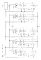
- the electrical storage device shown in FIGS. 2 , 4 , 5 , and 6 is assumed to include five rows of electrical storage systems G1, G2, G3, G4, and G5 (accordingly, the electrical storage device includes five switching parts S1, S2, S3, S4, and S5 that correspond respectively to the electrical storage systems G1, G2, G3, G4, and G5).
- the electrical storage device is performing charging/discharging operations, and that the switching parts S1, S2, and S3 are in the ON state and the switching parts S4 and S5 are in the OFF state as shown in FIG. 2 .
- the electrical storage systems G1, G2, and G3 are in the "charging/discharging operating state” and the electrical storage systems G4 and G5 are in the "non-charging/discharging state.”
- control part 10 has preset therein information regarding the subsequent sequence, in addition to the first threshold temperature. Specifically, the control part 10 has set therein information regarding the sequence in which the electrical storage systems G1, G2, G3, G4, and G5 are switched from the non-charging/discharging state to the charging/discharging operating state. Every time the temperature of one of the storage batteries 1 has reached the first threshold temperature, the control part 10 switches one of the electrical storage systems G1, G2, G3, G4, and G5 from the non-charging/discharging state to the charging/discharging operating state in accordance with the information regarding the sequence.
- FIG. 3 illustrates an example of the information regarding the sequence, and it is assumed that the information shown in FIG. 3 is set in the control part 10.
- the electrical storage system G4 is the first electrical storage system to be switched from the non-charging/discharging state to the charging/discharging operating state.
- the electrical storage system G5 is the second electrical storage system to be switched from the non-charging/discharging state to the charging/discharging operating state.
- the electrical storage system that was first to be switched from the charging/discharging operating state to the non-charging/discharging state is the third electrical storage system to be switched from the non-charging/discharging state to the charging/discharging operating state.
- the electrical storage system that was second to be switched from the charging/discharging operating state to the non-charging/discharging state is the fourth electrical storage system to be switched from the non-charging/discharging state to the charging/discharging operating state. That is, in the example shown in FIG. 3 , from the third switching onwards, the electrical storage systems G1 to G5 are switched from the non-charging/discharging state to the charging/discharging operating state in rotation, in the sequence in which electrical storage system switching was performed from the charging/discharging operating state to the non-charging/discharging state.
- an electrical storage system G1, G2, G3, G4, or G5 to be switched to the charging/discharging operating state includes an electrical storage battery 1 that has an abnormality or has a temperature higher than the first threshold value
- the electrical storage system G1, G2, G3, G4, or G5 that is in this state is not switched to and the next electrical storage system G1, G2, G3, G4, or G5 is selected.
- a controller not shown gives an alarm to notify that fact to the outside.
- control part 10 monitors the temperatures of the respective storage batteries 1 by referencing the temperature information transmitted from the temperature sensors 2.
- the result of the above temperature monitoring performed in the state shown in FIG. 2 shows that the temperature of an electrical storage battery 1 in the electrical storage systems G1, G2, and G3 that are in the charging/discharging operating state has increased considerably.
- the temperature of one of the storage batteries 1 hereinafter, referred to as an "electrical storage battery 1A"
- the control part 10 has received temperature information from the temperature sensor 2 provided for the electrical storage battery 1A and determined that the temperature of the electrical storage battery 1A has reached the first threshold temperature.
- the temperature sensor 2 also transmits its identification information to the control part 10, together with the temperature information. This allows the control part 10 to determine which of the electrical storage system G1 to G5 the temperature sensor 2 that has transmitted the temperature information belongs to (or which one of the storage batteries 1 belonging to one of the electrical storage systems G1 to G5 the temperature sensor that has transmitted the temperature information belongs to).
- the control part 10 determines that the temperature of the electrical storage battery 1A belonging to the electrical storage system G2 is high, and controls the switching part S2 provided for the electrical storage system G2 to which the electrical storage battery 1A belongs. Specifically, the control part 10 switches the switching part S2 from the ON state to the OFF state. Under the control of the control part 10, the electrical storage system G2 is switched from the charging/discharging operating state to the non-charging/discharging state (electrical storage system switching).
- control part 10 In response to the electrical storage system G2 having been switched from the charging/discharging operating state to the non-charging/discharging state, the control part 10 also performs the following control. Specifically, the control part 10 controls either of the switching parts S4 and S5 provided for the electrical storage systems G4 and G5, which are in the non-charging/discharging state prior to the switching. Under this control, either of the electrical storage systems G4 and G5 is switched from the non-charging/discharging state to the charging/discharging operating state.
- control part 10 has set therein the information regarding the sequence illustrated in FIG. 3 .
- the control part 10 controls the switching part S4 provided for the electrical storage system G4.
- the control part 10 switches the switching part S4 from the ON state to the OFF state.
- the electrical storage system G4 is switched from the non-charging/discharging state to the charging/discharging operating state (electrical storage system switching).
- the electrical storage device monitoring system 100 transitions from the state shown in FIG. 2 to the state shown in FIG. 4 .
- the storage batteries 1 belonging to the electrical storage system G2 are forcibly cooled by the cooler (not shown) during a period in which the electrical storage system G2 is in the non-charging/discharging state.
- the control part 10 has received the temperature information from the temperature sensor 2 provided for the electrical storage battery 1B and determined that the temperature of the electrical storage battery 1B has reached the first threshold temperature.
- the control part 10 determines that the temperature of the electrical storage battery 1B belonging to the electrical storage system G1 is high and controls the switching part S1 provided for the electrical storage system G1 to which the electrical storage battery 1B belongs. Specifically, the control part 10 switches the switching part S1 from the ON state to the OFF state. Under the control of the control part 10, the electrical storage system G1 is switched from the charging/discharging operating state to the non-charging/discharging state (electrical storage system switching).
- control part 10 In response to the electrical storage system G1 having been switched from the charging/discharging operating state to the non-charging/discharging state, the control part 10 also performs the following control. Specifically, the control part 10 controls either of the switching parts S2 and S5 provided for the electrical storage systems G2 and G5, which are in the non-charging/discharging state before the switching. Under this control, either of the electrical storage systems G2 and G5 is switched from the non-charging/discharging state to the charging/discharging operating state (electrical storage system switching).
- control part 10 has set therein the information regarding the sequence illustrated in FIG. 3 .
- the control part 10 controls the switching part S5 provided for the electrical storage system G5. Specifically, the control part 10 switches the switching part S5 from the OFF state to the ON state. Under the control of the control part 10, the electrical storage system G5 is switched from the non-charging/discharging state to the charging/discharging operating state.
- the electrical storage device monitoring system 100 transitions from the state shown in FIG. 4 to the state shown in FIG. 5 .
- the storage batteries 1 belonging to the electrical storage system G1 are forcibly cooled by the cooler (not shown) during the period in which the electrical storage system G1 is in the non-charging/discharging state.
- the temperature of one of the storage batteries 1 (hereinafter, referred to as an "electrical storage battery 1C") belonging to the electrical storage system G3, which is in the charging/discharging operating state, has increased considerably. It is also assumed that the control part 10 has received the temperature information from the temperature sensor 2 provided for the electrical storage battery 1C and determined that the temperature of the electrical storage battery 1C has reached the first threshold temperature.
- the control part 10 determines that the temperature of the electrical storage battery 1C belonging to the electrical storage system G3 is high and controls the switching part S3 provided for the electrical storage system G3 to which the electrical storage battery 1C belongs. Specifically, the control part 10 switches the switching part S3 from the ON state to the OFF state. Under the control of the control part 10, the electrical storage system G3 is switched from the charging/discharging operating state to the non-charging/discharging state (electrical storage system switching).
- control part 10 In response to the electrical storage system G3 having been switched from the charging/discharging operating state to the non-charging/discharging state, the control part 10 also performs the following control. Specifically, the control part 10 controls either of the switching parts S1 and S2 provided for the electrical storage systems G1 and G2, which are in the non-charging/discharging state prior to the switching. Under this control, either of the electrical storage systems G1 and G2 is switched from the non-charging/discharging state to the charging/discharging operating state.
- control part 10 has set therein the information regarding the sequence illustrated in FIG. 3 .
- the control part 10 controls the switching part S5 provided for the electrical storage system G2 (as described above, the electrical storage system G2 was the first to be switched from the charging/discharging operating state to the non-charging/discharging state).
- the control part 10 switches the switching part S2 from the OFF state to the ON state.
- the electrical storage system G2 is switched from the non-charging/discharging state to the charging/discharging operating state (electrical storage system switching). In other words, the electrical storage system G2 resumes charging/discharging operations.
- the storage batteries 1 belonging to the electrical storage system G2 are forcibly cooled by the cooler (not shown) during the period in which the electrical storage system G2 is in the non-charging/discharging state. Accordingly, the storage batteries 1 belonging to the electrical storage system G2, including the above electrical storage battery 1A, will resume charging/discharging operations in a low temperature state.
- the electrical storage device monitoring system 100 transitions from the state shown in FIG. 5 to the state shown in FIG. 6 .
- the electrical storage system G1 to G5 to which that electrical storage battery 1 belongs is switched from the charging/discharging operating state to the non-charging/discharging state, and in accordance with the sequence illustrated in FIG. 3 , one of the electrical storage systems G1 to G5 that is in the non-charging/discharging state is switched from the non-charging/discharging state to the charging/discharging operating state.
- the storage batteries 1 belonging to the electrical storage systems G1 to G5 that are in the non-charging/discharging state are then forcibly cooled by the cooler (not shown).
- the control part 10 monitors the temperatures of the respective storage batteries 1 on the basis of the temperature information transmitted from the temperature sensors 2.
- the control part 10 performs system switching in which a corresponding one of the switching parts S1 to S5 that is provided for the one of the electrical storage systems G1 to G5 including that the electrical storage battery 1 is controlled, and the one of the electrical storage systems G1 to G5 is switched from the charging/discharging operating state to the non-charging/discharging state.
- the control part 10 also performs system switching in which one of the switching parts S1 to G5 that is provided for one of the electrical storage systems G1 to G5 that is in the non-charging/discharging state is controlled, and the one of the electrical storage systems G1 to G5 is switched from the non-charging/discharging state to the charging/discharging operating state.
- an electrical storage device management system 100 that allows an electrical storage device to obtain high input/output currents continuously over a long period of time when charging/discharging.
- the electrical storage device can continue charging/discharging with high input/output currents.
- the electrical storage device management system 100 allows the electrical storage device to obtain high input/output currents continuously over a longer period of time when charging/discharging.
- the electrical storage device management system 100 includes a cooler.
- the storage batteries 1 can be forcibly cooled during the period of the non-charging/discharging state. It is thus possible to cool the storage batteries 1 to a sufficiently low temperature condition in a short time.
- the electrical storage systems G1 to G5 are each configured by series-connected storage batteries 1.
- each of the electrical storage systems G1 to GN may be configured by series-parallel connection of storage batteries 1 as shown in FIG. 7 .
- the electrical storage systems are each configured by series-parallel connection of storage batteries 1, the number of parallel rows, the number of series-connected storage batteries 1 in a single parallel connection, and the number of series-connected parallel connections are arbitrarily selected in accordance with the environment in which the electrical storage device is used.
Landscapes
- Engineering & Computer Science (AREA)
- Power Engineering (AREA)
- Secondary Cells (AREA)
- Manufacturing & Machinery (AREA)
- Chemical & Material Sciences (AREA)
- Chemical Kinetics & Catalysis (AREA)
- Electrochemistry (AREA)
- General Chemical & Material Sciences (AREA)
- Charge And Discharge Circuits For Batteries Or The Like (AREA)
Abstract
Description
- The present invention relates to an electrical storage battery management system for performing control during charging/discharging operations of an electrical storage device that includes electrical storage cells such as lithium ion batteries.
- Secondary batteries have undergone further development, and for example, lithium ion batteries have been receiving attention due to their high capacity, high energy density, and potential for size and weight reduction.
- An electrical storage device used as a power source for various electronic and electric devices is generally configured by series-parallel connection of a plurality of secondary batteries. When used as a power source, the electrical storage device is connected to an electronic or electric device and discharges electricity. In the case of charging the electrical storage device, the electrical storage device is connected to a power supply system.
-
Patent Document 1 is an example of a prior art document relating to lithium ion batteries.Patent Document 2 is an example of a prior art document relating to electrical storage devices. - A lithium ion battery according to
Patent Document 1 is capable of preventing overcharging/overdischarging and controlling battery temperature without retaining space for heat dissipation. An electrical storage device according toPatent Document 2 is capable of quick charging with high current and thereby reliably cutting the charging current off when the battery temperature becomes high. -
- Patent Document 1: Japanese Patent Application Laid-Open No.
10-334951 - (1998) Patent Document 2: Japanese Patent Application Laid-Open No.
2008-148419 - Electrical storage devices in recent years are required to obtain high input/output currents when charging/discharging. However, increasing the current value for charging/discharging causes an increase in the amount of heat generated by secondary batteries. This places a limitation on the method of using electrical storage devices, such as not being able to perform continuous (extended) charging/discharging, in order to reduce the amount of heat generated by the secondary batteries while obtaining high input/output currents when charging/discharging.
- In view of this, it is an object of the present invention to provide an electrical storage device management system that allows an electrical storage device to obtain high input/output currents continuously over a long period of time when charging/discharging.
- In order to achieve the object described above, the electrical storage device management system according to the present invention includes a plurality of rows of electrical storage systems, a plurality of chargeable/dischargeable electrical storage cells constituting each of the electrical storage systems, a plurality of switching parts provided in correspondence with the electrical storage systems, a plurality of temperature sensors provided in correspondence with the electrical storage cells and configured to detect temperatures of the corresponding electrical storage cells, and a control part connected to the switching parts and the temperature sensors. The control part has set therein a first threshold temperature. The control part is configured to (A) monitor the temperatures of the electrical storage cells on the basis of temperature information transmitted from the temperature sensors, and when a result of the operation (A) indicates that the temperature of one of the electrical storage cells has reached the first threshold temperature in one of the electrical storage systems that is in a charging/discharging operating state, (B) perform system switching in which the switching part that is disposed in correspondence with the electrical storage system that includes the electrical storage cell is controlled, and the electrical storage system is switched from the charging/discharging operating state to a non-charging/discharging state, and (C) perform system switching in which one of the switching parts that is disposed in correspondence with one of the electrical storage systems that is in the non-charging/discharging state is controlled, and the electrical storage system is switched from the non-charging/discharging state to the charging/discharging operating state.
- The electrical storage device management system according to the present invention includes a plurality of rows of electrical storage systems, a plurality of chargeable/dischargeable electrical storage cells constituting each of the electrical storage systems, a plurality of switching parts provided in correspondence with the electrical storage systems, a plurality of temperature sensors provided in correspondence with the electrical storage cells and configured to detect temperatures of the corresponding electrical storage cells, and a control part connected to the switching parts and the temperature sensors. The control part has set therein a first threshold temperature. The control part is configured to (A) monitor the temperatures of the electrical storage cells on the basis of temperature information transmitted from the temperature sensors, and when a result of the operation (A) indicates that the temperature of one of the electrical storage cells has reached the first threshold temperature in one of the electrical storage systems that is in a charging/discharging operating state, (B) perform system switching in which the switching part that is disposed in correspondence with the electrical storage system that includes the electrical storage cell is controlled, and the electrical storage system is switched from the charging/discharging operating state to a non-charging/discharging state, and (C) perform system switching in which one of the switching parts that is disposed in correspondence with one of the electrical storage systems that is in the non-charging/discharging state is controlled, and the electrical storage system is switched from the non-charging/discharging state to the charging/discharging operating state.
- Accordingly, it is possible to provide an electrical storage device management system that allows an electrical storage device to obtain high input/output currents continuously over a long period of time when charging/discharging.
- These and other objects, features, aspects and advantages of the present invention will become more apparent from the following detailed description of the present invention when taken in conjunction with the accompanying drawings.
-
-
FIG. 1 is a block diagram showing a configuration of an electrical storagedevice management system 100 according toEmbodiment 1. -
FIG. 2 illustrates operations of the electrical storagedevice management system 100 according toEmbodiment 1. -
FIG. 3 illustrates a sequence, set in acontrol part 10, in which electrical storage systems are switched from a non-charging/discharging state to a charging/discharging operating state. -
FIG. 4 illustrates operations of the electrical storagedevice management system 100 according toEmbodiment 1. -
FIG. 5 illustrates operations of the electrical storagedevice management system 100 according toEmbodiment 1. -
FIG. 6 illustrates operations of the electrical storagedevice management system 100 according toEmbodiment 1. -
FIG. 7 illustrates another configuration of electrical storage systems. - In the present invention, an electrical storage device is configured by a plurality of rows of electrical storage systems. Each of the electrical storage systems is configured by a plurality of chargeable/dischargeable electrical storage cells. The electrical storage systems are each provided with a switching part. In the electrical storage device according to the present invention, not all of the electrical storage systems perform charging/discharging operations during charging/discharging processing, and some of the electrical storage systems are in a non-charging/discharging state in which they do not perform charging/discharging operations.
- The electrical storage cells generate heat according to the current value during charging/discharging, and the electrical storage device management system according to the present invention monitors the temperatures of the respective electrical storage cells. If the temperature of one of the electrical storage cells becomes high, the electrical storage device management system controls the corresponding switching part so as to disconnect an electrical storage system that includes the high-temperature electrical storage cell (hereinafter, referred to as an electrical storage system A) from the charging/discharging processing.
- The electrical storage device management system also selects an arbitrary electrical storage system from among the electrical storage systems that are in the above non-charging/discharging state and controls the switching part connected to the selected electrical storage system. Under the control of the switching part, the selected electrical storage system (referred to as an "electrical storage system B") is switched from the non-charging/discharging state to a charging/discharging operating state, and the electrical storage system B performs charging/discharging operations, instead of the electrical storage system A.
- Hereinafter, an embodiment of the present invention will be described in detail with reference to the drawings.
- In the present embodiment, the electrical storage cells constituting the electrical storage systems are all storage batteries such as lithium ion batteries. In the description of the present embodiment, electrical storage cells are referred as "storage batteries."
-
FIG. 1 is a diagram illustrating a configuration of an electrical storagedevice management system 100 according to the present embodiment. InFIG. 1 , the configuration excluding acontrol part 10 can be regarded as an electrical storage device. The electrical storagedevice management system 100 includes the electrical storage device and thecontrol part 10, which is for monitoring and controlling the electrical storage device. - In the case of discharging, portions of the electrical storage device that are indicated by dashed lines in
FIG. 1 are connected to a load such as an electronic or electric device via a converter or the like, so that the electrical storage device functions as a power source for the load. The same portions indicated by dashed lines are also used in the case of charging via a converter or the like. - As shown in
FIG. 1 , the electrical storage device includes a plurality of rows of electrical storage systems G1, G2, G3, ..., GN-1, and GN. Here, as shown inFIG. 1 , the electrical storage systems G1, G2, G3, ..., GN-1, and GN are each configured by a plurality of chargeable/dischargeable storage batteries 1. Thestorage batteries 1 are chargeable/dischargeable secondary batteries and may be lithium ion batteries, for example. - In the exemplary configuration in
FIG. 1 , the electrical storage systems G1, G2, G3, ..., GN-1, and GN are each configured by a plurality of series-connectedstorage batteries 1. - The electrical storage systems G1, G2, G3, ...,GN-1, and GN are respectively provided with switching parts S1, S2, S3, ..., SN-1, and SN as shown in
FIG. 1 . - Specifically, as shown in
Fig. 1 , the switching part S1 is connected to anelectrical storage battery 1 that is located at one end of the electrical storage system G1. The switching part S2 is connected to anelectrical storage battery 1 that is located at one end of the electrical storage system G2. The switching part S3 is connected to anelectrical storage battery 1 that is located at one end of the electrical storage system G3. The switching part SN-1 is connected to anelectrical storage battery 1 that is located at one end of the electrical storage system GN-1. The switching part SN is connected to anelectrical storage battery 1 that is located at one end of the electrical storage system GN. - The current input/output ends of the switching parts S1 to SN-1 are commonly connected to one another by wiring (see one side of the portions indicated by dashed lines).
- The switching parts S1, S2, S3, ..., SN-1, and SN are connected to the
control part 10 so as to be capable of transmitting and receiving data and signals, for example. The switching parts S1, S2, S3, ..., SN-1, and SN are turned on or off under the control of thecontrol part 10. - When the switching parts S1, S2, S3, ..., SN-1, and SN are in the ON state, the electrical storage systems G1, G2, G3, ...,GN-1, and GN connected to the switching parts S1, S2, S3, ..., SN-1, and SN are chargeable/dischargeable (i.e., they are in the charging/discharging operating state). On the other hand, when the switching parts S1, S2, S3, ..., SN-1, and SN are in the OFF state, the electrical storage systems G1, G2, G3, ...,GN-1, and GN connected to the switching parts S1, S2, S3, ..., SN-1, and SN are not chargeable/dischargeable (i.e., they are in the non-charging/discharging state).
- The electrical storage
device management system 100 also includes a plurality oftemperature sensors 2 as shown inFIG. 1 . Each of thetemperature sensors 2 is disposed in correspondence with and in the vicinity of one of thestorage batteries 1. - The
temperature sensors 2 are connected to thecontrol part 10 so as to be capable of transmitting and receiving data and signals, for example. Each of thetemperature sensors 2 detects the temperature of the correspondingelectrical storage battery 1. Thetemperature sensors 2 then transmit detection results (temperature information) to thecontrol part 10. - The
control part 10 of the electrical storagedevice management system 100 is communicably connected to the switching parts S1, S2, S3, ..., SN-1, and SN and thetemperature sensors 2 as described above. - The
control part 10 receives the temperature information transmitted from thetemperature sensors 2. Thecontrol part 10 also has preset therein a first threshold temperature. Here, a temperature in the high temperature zone is selected as the first threshold temperature, and for example, a maximum temperature at which thestorage batteries 2 are capable of normally inputting and outputting a rated current (or a temperature slightly lower than this maximum temperature) can be employed as the first threshold temperature. - The
control part 10 uses the above temperature information and the above first threshold temperature to control on/off switching of the switching parts S1, S2, S3, ..., SN-1, and SN. Note that specific operations of controlling on/off switching of the switching parts S1, S2, S3, ..., SN-1, and SN, performed by thecontrol part 10, will be described later. Apart from being used for temperature control, the switching parts S1, S2, S3, ..., SN-1, and SN may also be used to disconnect a specific battery system if there are any abnormalities in individual batteries, or may be used for maintenance. - Although not shown in
FIG. 1 , the electrical storagedevice monitoring system 100 also includes a cooler for cooling thestorage batteries 1. - The cooler may be disposed for each of the
storage batteries 1, a single cooler may be provided for each predetermined number of thestorage batteries 1, or a single cooler may be provided for all of thestorage batteries 1. - The cooler may be known cooling means and may be a fan or the like, for example. The
storage batteries 1 are forcibly cooled by the cooler. - Next, the operations of the electrical storage
device monitoring system 100 according to the present embodiment will be described with reference toFIGS. 2 ,4 ,5 , and6 . - To simplify the description, the electrical storage device shown in
FIGS. 2 ,4 ,5 , and6 is assumed to include five rows of electrical storage systems G1, G2, G3, G4, and G5 (accordingly, the electrical storage device includes five switching parts S1, S2, S3, S4, and S5 that correspond respectively to the electrical storage systems G1, G2, G3, G4, and G5). - It is assumed that the electrical storage device is performing charging/discharging operations, and that the switching parts S1, S2, and S3 are in the ON state and the switching parts S4 and S5 are in the OFF state as shown in
FIG. 2 . In other words, the electrical storage systems G1, G2, and G3 are in the "charging/discharging operating state" and the electrical storage systems G4 and G5 are in the "non-charging/discharging state." - Moreover, the
control part 10 has preset therein information regarding the subsequent sequence, in addition to the first threshold temperature. Specifically, thecontrol part 10 has set therein information regarding the sequence in which the electrical storage systems G1, G2, G3, G4, and G5 are switched from the non-charging/discharging state to the charging/discharging operating state. Every time the temperature of one of thestorage batteries 1 has reached the first threshold temperature, thecontrol part 10 switches one of the electrical storage systems G1, G2, G3, G4, and G5 from the non-charging/discharging state to the charging/discharging operating state in accordance with the information regarding the sequence. -
FIG. 3 illustrates an example of the information regarding the sequence, and it is assumed that the information shown inFIG. 3 is set in thecontrol part 10. - In the example of
FIG. 3 , the electrical storage system G4 is the first electrical storage system to be switched from the non-charging/discharging state to the charging/discharging operating state. The electrical storage system G5 is the second electrical storage system to be switched from the non-charging/discharging state to the charging/discharging operating state. The electrical storage system that was first to be switched from the charging/discharging operating state to the non-charging/discharging state is the third electrical storage system to be switched from the non-charging/discharging state to the charging/discharging operating state. The electrical storage system that was second to be switched from the charging/discharging operating state to the non-charging/discharging state is the fourth electrical storage system to be switched from the non-charging/discharging state to the charging/discharging operating state. That is, in the example shown inFIG. 3 , from the third switching onwards, the electrical storage systems G1 to G5 are switched from the non-charging/discharging state to the charging/discharging operating state in rotation, in the sequence in which electrical storage system switching was performed from the charging/discharging operating state to the non-charging/discharging state. - However, if an electrical storage system G1, G2, G3, G4, or G5 to be switched to the charging/discharging operating state includes an
electrical storage battery 1 that has an abnormality or has a temperature higher than the first threshold value, the electrical storage system G1, G2, G3, G4, or G5 that is in this state is not switched to and the next electrical storage system G1, G2, G3, G4, or G5 is selected. If none of the electrical storage system G1, G2, G3, G4, and G5 can be switched to, a controller (not shown) gives an alarm to notify that fact to the outside. - When the electrical storage device starts charging or discharging, the
control part 10 monitors the temperatures of therespective storage batteries 1 by referencing the temperature information transmitted from thetemperature sensors 2. - Assume that the result of the above temperature monitoring performed in the state shown in
FIG. 2 shows that the temperature of anelectrical storage battery 1 in the electrical storage systems G1, G2, and G3 that are in the charging/discharging operating state has increased considerably. For example, assume that the temperature of one of the storage batteries 1 (hereinafter, referred to as an "electrical storage battery 1A") that belong to the electrical storage system G2 which is in the charging/discharging operating state has increased considerably. Assume also that thecontrol part 10 has received temperature information from thetemperature sensor 2 provided for the electrical storage battery 1A and determined that the temperature of the electrical storage battery 1A has reached the first threshold temperature. - Here, if each of the
temperature sensors 2 has set therein identification information or the like, thetemperature sensor 2 also transmits its identification information to thecontrol part 10, together with the temperature information. This allows thecontrol part 10 to determine which of the electrical storage system G1 to G5 thetemperature sensor 2 that has transmitted the temperature information belongs to (or which one of thestorage batteries 1 belonging to one of the electrical storage systems G1 to G5 the temperature sensor that has transmitted the temperature information belongs to). - In the above-described case, the
control part 10 determines that the temperature of the electrical storage battery 1A belonging to the electrical storage system G2 is high, and controls the switching part S2 provided for the electrical storage system G2 to which the electrical storage battery 1A belongs. Specifically, thecontrol part 10 switches the switching part S2 from the ON state to the OFF state. Under the control of thecontrol part 10, the electrical storage system G2 is switched from the charging/discharging operating state to the non-charging/discharging state (electrical storage system switching). - In response to the electrical storage system G2 having been switched from the charging/discharging operating state to the non-charging/discharging state, the
control part 10 also performs the following control. Specifically, thecontrol part 10 controls either of the switching parts S4 and S5 provided for the electrical storage systems G4 and G5, which are in the non-charging/discharging state prior to the switching. Under this control, either of the electrical storage systems G4 and G5 is switched from the non-charging/discharging state to the charging/discharging operating state. - Specifically, the
control part 10 has set therein the information regarding the sequence illustrated inFIG. 3 . In accordance withFIG. 3 (see the first in the sequence inFIG. 3 ), thecontrol part 10 controls the switching part S4 provided for the electrical storage system G4. Specifically, thecontrol part 10 switches the switching part S4 from the ON state to the OFF state. Under the control of thecontrol part 10, the electrical storage system G4 is switched from the non-charging/discharging state to the charging/discharging operating state (electrical storage system switching). - As a result of the
control part 10 having detected that the temperature of the electrical storage battery 1A is high (has reached the first threshold temperature) and having performed the aforementioned electrical storage system switching, the electrical storagedevice monitoring system 100 transitions from the state shown inFIG. 2 to the state shown inFIG. 4 . Here, thestorage batteries 1 belonging to the electrical storage system G2 are forcibly cooled by the cooler (not shown) during a period in which the electrical storage system G2 is in the non-charging/discharging state. - Assume, for example, that the result of the above temperature monitoring performed in the state illustrated in
FIG. 4 shows that the temperature of one of the storage batteries 1 (hereinafter, referred to as an "electrical storage battery 1B") belonging to the electrical storage system G1, which is in the charging/discharging operating state, has increased considerably. Assume also that thecontrol part 10 has received the temperature information from thetemperature sensor 2 provided for the electrical storage battery 1B and determined that the temperature of the electrical storage battery 1B has reached the first threshold temperature. - In the above case, the
control part 10 determines that the temperature of the electrical storage battery 1B belonging to the electrical storage system G1 is high and controls the switching part S1 provided for the electrical storage system G1 to which the electrical storage battery 1B belongs. Specifically, thecontrol part 10 switches the switching part S1 from the ON state to the OFF state. Under the control of thecontrol part 10, the electrical storage system G1 is switched from the charging/discharging operating state to the non-charging/discharging state (electrical storage system switching). - In response to the electrical storage system G1 having been switched from the charging/discharging operating state to the non-charging/discharging state, the
control part 10 also performs the following control. Specifically, thecontrol part 10 controls either of the switching parts S2 and S5 provided for the electrical storage systems G2 and G5, which are in the non-charging/discharging state before the switching. Under this control, either of the electrical storage systems G2 and G5 is switched from the non-charging/discharging state to the charging/discharging operating state (electrical storage system switching). - To be more specific, the
control part 10 has set therein the information regarding the sequence illustrated inFIG. 3 . In accordance withFIG. 3 (see the second in the sequence inFIG. 3 ), thecontrol part 10 controls the switching part S5 provided for the electrical storage system G5. Specifically, thecontrol part 10 switches the switching part S5 from the OFF state to the ON state. Under the control of thecontrol part 10, the electrical storage system G5 is switched from the non-charging/discharging state to the charging/discharging operating state. - As a result of the
control part 10 having detected, in the state illustrated inFIG. 4 , that the temperature of the electrical storage battery 1B is high (has reached the first threshold temperature) and having performed the above electrical storage system switching, the electrical storagedevice monitoring system 100 transitions from the state shown inFIG. 4 to the state shown inFIG. 5 . Here, thestorage batteries 1 belonging to the electrical storage system G1 are forcibly cooled by the cooler (not shown) during the period in which the electrical storage system G1 is in the non-charging/discharging state. - As a result of the above temperature monitoring performed in the state shown in
FIG. 5 , it is assumed that the temperature of one of the storage batteries 1 (hereinafter, referred to as an "electrical storage battery 1C") belonging to the electrical storage system G3, which is in the charging/discharging operating state, has increased considerably. It is also assumed that thecontrol part 10 has received the temperature information from thetemperature sensor 2 provided for the electrical storage battery 1C and determined that the temperature of the electrical storage battery 1C has reached the first threshold temperature. - In the above case, the
control part 10 determines that the temperature of the electrical storage battery 1C belonging to the electrical storage system G3 is high and controls the switching part S3 provided for the electrical storage system G3 to which the electrical storage battery 1C belongs. Specifically, thecontrol part 10 switches the switching part S3 from the ON state to the OFF state. Under the control of thecontrol part 10, the electrical storage system G3 is switched from the charging/discharging operating state to the non-charging/discharging state (electrical storage system switching). - In response to the electrical storage system G3 having been switched from the charging/discharging operating state to the non-charging/discharging state, the
control part 10 also performs the following control. Specifically, thecontrol part 10 controls either of the switching parts S1 and S2 provided for the electrical storage systems G1 and G2, which are in the non-charging/discharging state prior to the switching. Under this control, either of the electrical storage systems G1 and G2 is switched from the non-charging/discharging state to the charging/discharging operating state. - To be more specific, the
control part 10 has set therein the information regarding the sequence illustrated inFIG. 3 . In accordance withFIG. 3 (see the third in the sequence inFIG. 3 ), thecontrol part 10 controls the switching part S5 provided for the electrical storage system G2 (as described above, the electrical storage system G2 was the first to be switched from the charging/discharging operating state to the non-charging/discharging state). Specifically, thecontrol part 10 switches the switching part S2 from the OFF state to the ON state. Under the control of thecontrol part 10, the electrical storage system G2 is switched from the non-charging/discharging state to the charging/discharging operating state (electrical storage system switching). In other words, the electrical storage system G2 resumes charging/discharging operations. - Here, as described above, the
storage batteries 1 belonging to the electrical storage system G2 are forcibly cooled by the cooler (not shown) during the period in which the electrical storage system G2 is in the non-charging/discharging state. Accordingly, thestorage batteries 1 belonging to the electrical storage system G2, including the above electrical storage battery 1A, will resume charging/discharging operations in a low temperature state. - As a result of the
control part 10 having detected, in the state shown inFIG. 5 , that the temperature of the electrical storage battery 1C is high (has reached the first threshold temperature) and having performed the above electrical storage system switching, the electrical storagedevice monitoring system 100 transitions from the state shown inFIG. 5 to the state shown inFIG. 6 . - Thereafter, in the same manner as described above, every time one of the
storage batteries 1 has reached the first threshold temperature, the electrical storage system G1 to G5 to which thatelectrical storage battery 1 belongs is switched from the charging/discharging operating state to the non-charging/discharging state, and in accordance with the sequence illustrated inFIG. 3 , one of the electrical storage systems G1 to G5 that is in the non-charging/discharging state is switched from the non-charging/discharging state to the charging/discharging operating state. Thestorage batteries 1 belonging to the electrical storage systems G1 to G5 that are in the non-charging/discharging state are then forcibly cooled by the cooler (not shown). - As described above, in the electrical storage
device management system 100 according to the present embodiment, thecontrol part 10 monitors the temperatures of therespective storage batteries 1 on the basis of the temperature information transmitted from thetemperature sensors 2. When the result of the monitoring shows that the temperature of one of thestorage batteries 1 has reached the first threshold temperature in one of the electrical storage systems G1 to G5 that is in the charging/discharging operating state, thecontrol part 10 performs system switching in which a corresponding one of the switching parts S1 to S5 that is provided for the one of the electrical storage systems G1 to G5 including that theelectrical storage battery 1 is controlled, and the one of the electrical storage systems G1 to G5 is switched from the charging/discharging operating state to the non-charging/discharging state. Thecontrol part 10 also performs system switching in which one of the switching parts S1 to G5 that is provided for one of the electrical storage systems G1 to G5 that is in the non-charging/discharging state is controlled, and the one of the electrical storage systems G1 to G5 is switched from the non-charging/discharging state to the charging/discharging operating state. - Accordingly, it is possible to provide an electrical storage
device management system 100 that allows an electrical storage device to obtain high input/output currents continuously over a long period of time when charging/discharging. - In other words, when the temperature of one of the
storage batteries 1 becomes high, a corresponding one of the electrical storage systems G1 to G5 to which thiselectrical storage battery 1 belongs is switched to the non-charging/discharging state. During the period of the non-charging/discharging state, the one of the electrical storage systems G1 to G5 performs neither charging nor discharging, and the input/output of current is also stopped. It is thus possible to cool thestorage batteries 1 belonging to the corresponding one of the electrical storage systems G1 to G5. Even if one of the electrical storage systems G1 to G5 is switched to the non-charging/discharging state, one of the other electrical storage systems G1 to G5 that are in the non-charging/discharging state is instead switched to the charging/discharging operating state. Accordingly, even if one of the electrical storage systems G1 to G5 transitions to the non-charging/discharging state, the electrical storage device can continue charging/discharging with high input/output currents. - In addition, every time one of the
storage batteries 1 has reached the first threshold temperature, the operation of switching the electrical storage systems G1 to G5 is performed in rotation as described above. Accordingly, even if the electrical storage device continues to obtain high input/output currents when charging/discharging, an excessive increase in the temperatures of thestorage batteries 1 can be prevented. As described above, the heat generated by the current flow during charging/discharging will not cause an excessive increase in the temperatures of thestorage batteries 1. Thus, the electrical storagedevice management system 100 allows the electrical storage device to obtain high input/output currents continuously over a longer period of time when charging/discharging. - Moreover, the electrical storage
device management system 100 according to the present embodiment includes a cooler. Thus, thestorage batteries 1 can be forcibly cooled during the period of the non-charging/discharging state. It is thus possible to cool thestorage batteries 1 to a sufficiently low temperature condition in a short time. - In
Embodiment 1, the electrical storage systems G1 to G5 are each configured by series-connectedstorage batteries 1. Alternatively, each of the electrical storage systems G1 to GN may be configured by series-parallel connection ofstorage batteries 1 as shown inFIG. 7 . - In the case where the electrical storage systems are each configured by series-parallel connection of
storage batteries 1, the number of parallel rows, the number of series-connectedstorage batteries 1 in a single parallel connection, and the number of series-connected parallel connections are arbitrarily selected in accordance with the environment in which the electrical storage device is used. - While the invention has been shown and described in detail, the foregoing description is in all aspects illustrative and not restrictive. It is therefore understood that numerous modifications and variations can be devised without departing from the scope of the invention.
-
- 1
- Electrical storage battery
- 2
- Temperature sensor
- 10
- Controller
- G1, G2, G3, G4, G5, GN-1, GN
- Electrical storage system
- S1, S2, S3, S4, S5, SN-1, SN
- Switching part
- 100
- Electrical storage device management system
Claims (4)
- An electrical storage device management system, comprising:a plurality of rows of electrical storage systems (Gl, G2, G3, G4, G5, GN-1, GN);a plurality of chargeable/dischargeable electrical storage cells (1) constituting each of said electrical storage systems;a plurality of switching parts (S1, S2, S3, S4, S5, SN-1, SN) provided in correspondence with said electrical storage systems;a plurality of temperature sensors (2) provided in correspondence with said electrical storage cells and configured to detect temperatures of said corresponding electrical storage cells; anda control part (10) connected to said switching parts and said temperature sensors,wherein said control part has set therein a first threshold temperature, andsaid control part is configured to:(A) monitor the temperatures of said electrical storage cells on the basis of temperature information transmitted from said temperature sensors; and
when a result of said (A) indicates that the temperature of one of said electrical storage cells has reached said first threshold temperature in one of said electrical storage systems that is in a charging/discharging operating state,(B) perform system switching in which said switching part that is disposed in correspondence with said electrical storage system that includes said electrical storage cell is controlled, and said electrical storage system is switched from the charging/discharging operating state to a non-charging/discharging state, and(C) perform system switching in which one of said switching parts that is disposed in correspondence with one of said electrical storage systems that is in the non-charging/discharging state is controlled, and said electrical storage system is switched from the non-charging/discharging state to the charging/discharging operating state. - The electrical storage device management system according to claim 1, wherein
said electrical storage cells are storage batteries (1). - The electrical storage device management system according to claim 2, wherein
said control part (10) has set therein a sequence in which said electrical storage systems (G1, G2, G3, G4, G5, GN-1, GN) are to be switched from the non-charging/discharging state to the charging/discharging operating state, and
every time the temperature of one of said electrical storage cells (1) reaches said first threshold temperature, said control part (10) performs said system switching of said (B) and performs said system switching of said (C) in accordance with said sequence. - The electrical storage device management system according to claim 1, further comprising:a cooler configured to cool said electrical storage cells.
Applications Claiming Priority (1)
| Application Number | Priority Date | Filing Date | Title |
|---|---|---|---|
| PCT/JP2011/074177 WO2013057821A1 (en) | 2011-10-20 | 2011-10-20 | Electricity storage device control system |
Publications (3)
| Publication Number | Publication Date |
|---|---|
| EP2770607A1 true EP2770607A1 (en) | 2014-08-27 |
| EP2770607A4 EP2770607A4 (en) | 2015-06-03 |
| EP2770607B1 EP2770607B1 (en) | 2025-06-25 |
Family
ID=48140498
Family Applications (1)
| Application Number | Title | Priority Date | Filing Date |
|---|---|---|---|
| EP11874140.4A Active EP2770607B1 (en) | 2011-10-20 | 2011-10-20 | Electricity storage device control system |
Country Status (7)
| Country | Link |
|---|---|
| US (1) | US9391465B2 (en) |
| EP (1) | EP2770607B1 (en) |
| JP (1) | JP5739005B2 (en) |
| KR (1) | KR101612645B1 (en) |
| CN (1) | CN103891096B (en) |
| ES (1) | ES3040292T3 (en) |
| WO (1) | WO2013057821A1 (en) |
Families Citing this family (9)
| Publication number | Priority date | Publication date | Assignee | Title |
|---|---|---|---|---|
| RU2569676C1 (en) * | 2012-08-02 | 2015-11-27 | Ниссан Мотор Ко., Лтд. | Battery charge control system for automatically guided vehicle and method for control of battery charge for automatically guided vehicle |
| MX338060B (en) * | 2012-08-02 | 2016-04-01 | Nissan Motor | Charging management system for unpiloted conveyance vehicle and charging management method. |
| AT513230A1 (en) * | 2012-08-10 | 2014-02-15 | Fronius Int Gmbh | PORTABLE WELDING ARRANGEMENT AND METHOD FOR OPERATING A PORTABLE WELDING ASSEMBLY |
| US20150069975A1 (en) * | 2013-09-12 | 2015-03-12 | Lincoln Global, Inc. | Staggering charging batteries |
| CN105811488A (en) * | 2014-12-31 | 2016-07-27 | 龙能科技(苏州)有限公司 | Mobile energy storage charging system |
| US20180152038A1 (en) * | 2016-11-25 | 2018-05-31 | Charles Gayle | Dual zone controller |
| JP6832962B2 (en) * | 2017-02-10 | 2021-02-24 | 本田技研工業株式会社 | Battery management system, mobile, battery, and battery management method |
| DE102023111390A1 (en) | 2023-05-03 | 2024-11-07 | Wacker Neuson Produktion GmbH & Co. KG | Electric battery and battery charging system with cooling mode |
| CN116799967B (en) * | 2023-08-25 | 2023-12-22 | 广东可信新能源股份有限公司 | An energy storage device charge and discharge management monitoring device and its monitoring method |
Family Cites Families (22)
| Publication number | Priority date | Publication date | Assignee | Title |
|---|---|---|---|---|
| DE4216045A1 (en) * | 1992-05-15 | 1993-11-18 | Bosch Gmbh Robert | Multiple charger |
| JP3281692B2 (en) | 1993-10-29 | 2002-05-13 | 三洋電機株式会社 | How to charge multiple rechargeable batteries |
| JPH08251714A (en) * | 1995-03-10 | 1996-09-27 | Mitsubishi Motors Corp | Electric vehicle power supply |
| JP3972383B2 (en) * | 1996-03-26 | 2007-09-05 | 日産自動車株式会社 | Battery pack for electric vehicles |
| JP3367382B2 (en) | 1997-05-30 | 2003-01-14 | トヨタ自動車株式会社 | Lithium ion secondary battery |
| JP2001185228A (en) * | 1999-12-24 | 2001-07-06 | Sanyo Electric Co Ltd | Electric power supply equipped with battery |
| JP4116756B2 (en) | 2000-05-12 | 2008-07-09 | 松下電器産業株式会社 | Abnormality detection device for battery pack |
| JP4433656B2 (en) | 2002-01-29 | 2010-03-17 | ソニー株式会社 | Information processing device |
| JP3469228B2 (en) * | 2002-02-13 | 2003-11-25 | 三菱重工業株式会社 | Power storage device charge / discharge control device, charge / discharge control method, and power storage system |
| JP4572850B2 (en) * | 2006-03-24 | 2010-11-04 | 株式会社日立製作所 | Power control device |
| JP5064776B2 (en) | 2006-12-07 | 2012-10-31 | 三洋電機株式会社 | Pack battery |
| JP2009011138A (en) * | 2007-06-29 | 2009-01-15 | Toyota Motor Corp | Power supply system, vehicle equipped with the same, control method of power supply system, and computer-readable recording medium recording a program for causing a computer to execute the control method |
| JP2010004627A (en) | 2008-06-19 | 2010-01-07 | Toyota Motor Corp | Charging system and method for charging |
| JP2010220280A (en) * | 2009-03-13 | 2010-09-30 | Panasonic Corp | Charging/discharging control circuit, power source device and method for controlling power source device |
| DE102009001670A1 (en) | 2009-03-19 | 2010-09-23 | Robert Bosch Gmbh | Charging method and charging system |
| JP5738519B2 (en) * | 2009-03-27 | 2015-06-24 | 伊藤忠商事株式会社 | Battery control device, vehicle, and battery control method |
| JP5517477B2 (en) * | 2009-03-30 | 2014-06-11 | 株式会社日本総合研究所 | Battery control device, vehicle, and battery control method |
| US8917061B2 (en) * | 2009-09-18 | 2014-12-23 | Schneider Electric It Corporation | System and method for battery cell balancing |
| JP5597208B2 (en) * | 2009-12-15 | 2014-10-01 | 日本碍子株式会社 | Secondary battery control device and secondary battery control method |
| EP2543107A4 (en) | 2010-03-01 | 2014-07-02 | Boston Power Inc | THERMAL SENSOR DEVICE WITH INFORMATION RETURN ON AVERAGE TEMPERATURE AND HOT POINT |
| JP5455725B2 (en) | 2010-03-15 | 2014-03-26 | 三菱重工業株式会社 | Assembled battery |
| JP5463324B2 (en) | 2011-06-01 | 2014-04-09 | 三菱重工業株式会社 | Assembled battery system |
-
2011
- 2011-10-20 ES ES11874140T patent/ES3040292T3/en active Active
- 2011-10-20 KR KR1020147007482A patent/KR101612645B1/en active Active
- 2011-10-20 US US14/342,971 patent/US9391465B2/en active Active
- 2011-10-20 CN CN201180074234.5A patent/CN103891096B/en active Active
- 2011-10-20 JP JP2013539464A patent/JP5739005B2/en active Active
- 2011-10-20 EP EP11874140.4A patent/EP2770607B1/en active Active
- 2011-10-20 WO PCT/JP2011/074177 patent/WO2013057821A1/en not_active Ceased
Also Published As
| Publication number | Publication date |
|---|---|
| WO2013057821A1 (en) | 2013-04-25 |
| EP2770607B1 (en) | 2025-06-25 |
| US20140239912A1 (en) | 2014-08-28 |
| EP2770607A4 (en) | 2015-06-03 |
| ES3040292T3 (en) | 2025-10-29 |
| KR20140054320A (en) | 2014-05-08 |
| JP5739005B2 (en) | 2015-06-24 |
| CN103891096A (en) | 2014-06-25 |
| JPWO2013057821A1 (en) | 2015-04-02 |
| KR101612645B1 (en) | 2016-04-26 |
| US9391465B2 (en) | 2016-07-12 |
| CN103891096B (en) | 2016-10-26 |
Similar Documents
| Publication | Publication Date | Title |
|---|---|---|
| EP2770607B1 (en) | Electricity storage device control system | |
| EP3183791B1 (en) | Electric storage system | |
| KR101321189B1 (en) | Power storage system | |
| US9362757B2 (en) | Solid-state active switch matrix for high energy, moderate power battery systems | |
| US10461546B2 (en) | System and method of managing battery by using balancing battery | |
| EP2658027A1 (en) | Power supply system | |
| US7956579B2 (en) | Battery charge management system for charging a battery bank that includes a plurality of batteries | |
| EP3525314A1 (en) | Overcharge prevention device and method | |
| US9680320B2 (en) | Battery control apparatus | |
| WO2017109500A1 (en) | Multi-module battery control | |
| US20130293198A1 (en) | Battery assembly control system | |
| CN102804476B (en) | Secondary battery | |
| JP2012065538A (en) | Power storage system | |
| EP1826863A2 (en) | Charging apparatus | |
| CN102577002A (en) | Electricity storage system | |
| EP2973934A1 (en) | Detection and prevention of short formation in battery packs | |
| US20160372969A1 (en) | Device and Method for Wiring a Battery Management System | |
| JP2009301941A (en) | Secondary battery pack | |
| JP2013162597A (en) | Assembled battery discharge control system and assembled battery discharge control method | |
| CN105556785B (en) | Battery system | |
| CN112531853B (en) | Main battery system management unit and protection method of battery single cabinet group parallel charging and discharging system | |
| KR102859416B1 (en) | Battery control system, battery control method, power supply apparatus and electric vehicle | |
| CN108336779A (en) | Battery module and the battery system for having it | |
| GB2614718A (en) | Battery system for an electric vehicle | |
| JP2012043581A (en) | Energy storage device |
Legal Events
| Date | Code | Title | Description |
|---|---|---|---|
| PUAI | Public reference made under article 153(3) epc to a published international application that has entered the european phase |
Free format text: ORIGINAL CODE: 0009012 |
|
| 17P | Request for examination filed |
Effective date: 20140407 |
|
| AK | Designated contracting states |
Kind code of ref document: A1 Designated state(s): AL AT BE BG CH CY CZ DE DK EE ES FI FR GB GR HR HU IE IS IT LI LT LU LV MC MK MT NL NO PL PT RO RS SE SI SK SM TR |
|
| DAX | Request for extension of the european patent (deleted) | ||
| RA4 | Supplementary search report drawn up and despatched (corrected) |
Effective date: 20150504 |
|
| RIC1 | Information provided on ipc code assigned before grant |
Ipc: H02J 7/04 20060101AFI20150427BHEP Ipc: H02J 7/00 20060101ALI20150427BHEP Ipc: H02J 7/02 20060101ALI20150427BHEP |
|
| STAA | Information on the status of an ep patent application or granted ep patent |
Free format text: STATUS: EXAMINATION IS IN PROGRESS |
|
| 17Q | First examination report despatched |
Effective date: 20200907 |
|
| GRAP | Despatch of communication of intention to grant a patent |
Free format text: ORIGINAL CODE: EPIDOSNIGR1 |
|
| STAA | Information on the status of an ep patent application or granted ep patent |
Free format text: STATUS: GRANT OF PATENT IS INTENDED |
|
| INTG | Intention to grant announced |
Effective date: 20250310 |
|
| RIN1 | Information on inventor provided before grant (corrected) |
Inventor name: HANADA, MASATO |
|
| RAP3 | Party data changed (applicant data changed or rights of an application transferred) |
Owner name: TMEIC CORPORATION |
|
| GRAS | Grant fee paid |
Free format text: ORIGINAL CODE: EPIDOSNIGR3 |
|
| GRAA | (expected) grant |
Free format text: ORIGINAL CODE: 0009210 |
|
| STAA | Information on the status of an ep patent application or granted ep patent |
Free format text: STATUS: THE PATENT HAS BEEN GRANTED |
|
| AK | Designated contracting states |
Kind code of ref document: B1 Designated state(s): AL AT BE BG CH CY CZ DE DK EE ES FI FR GB GR HR HU IE IS IT LI LT LU LV MC MK MT NL NO PL PT RO RS SE SI SK SM TR |
|
| REG | Reference to a national code |
Ref country code: GB Ref legal event code: FG4D |
|
| REG | Reference to a national code |
Ref country code: CH Ref legal event code: EP |
|
| REG | Reference to a national code |
Ref country code: CH Ref legal event code: EP |
|
| REG | Reference to a national code |
Ref country code: IE Ref legal event code: FG4D |
|
| REG | Reference to a national code |
Ref country code: DE Ref legal event code: R096 Ref document number: 602011075380 Country of ref document: DE |
|
| PG25 | Lapsed in a contracting state [announced via postgrant information from national office to epo] |
Ref country code: FI Free format text: LAPSE BECAUSE OF FAILURE TO SUBMIT A TRANSLATION OF THE DESCRIPTION OR TO PAY THE FEE WITHIN THE PRESCRIBED TIME-LIMIT Effective date: 20250625 |
|
| REG | Reference to a national code |
Ref country code: LT Ref legal event code: MG9D |
|
| PG25 | Lapsed in a contracting state [announced via postgrant information from national office to epo] |
Ref country code: GR Free format text: LAPSE BECAUSE OF FAILURE TO SUBMIT A TRANSLATION OF THE DESCRIPTION OR TO PAY THE FEE WITHIN THE PRESCRIBED TIME-LIMIT Effective date: 20250926 Ref country code: NO Free format text: LAPSE BECAUSE OF FAILURE TO SUBMIT A TRANSLATION OF THE DESCRIPTION OR TO PAY THE FEE WITHIN THE PRESCRIBED TIME-LIMIT Effective date: 20250925 |
|
| PG25 | Lapsed in a contracting state [announced via postgrant information from national office to epo] |
Ref country code: BG Free format text: LAPSE BECAUSE OF FAILURE TO SUBMIT A TRANSLATION OF THE DESCRIPTION OR TO PAY THE FEE WITHIN THE PRESCRIBED TIME-LIMIT Effective date: 20250625 |
|
| PG25 | Lapsed in a contracting state [announced via postgrant information from national office to epo] |
Ref country code: HR Free format text: LAPSE BECAUSE OF FAILURE TO SUBMIT A TRANSLATION OF THE DESCRIPTION OR TO PAY THE FEE WITHIN THE PRESCRIBED TIME-LIMIT Effective date: 20250625 |
|
| PG25 | Lapsed in a contracting state [announced via postgrant information from national office to epo] |
Ref country code: RS Free format text: LAPSE BECAUSE OF FAILURE TO SUBMIT A TRANSLATION OF THE DESCRIPTION OR TO PAY THE FEE WITHIN THE PRESCRIBED TIME-LIMIT Effective date: 20250925 |
|
| PG25 | Lapsed in a contracting state [announced via postgrant information from national office to epo] |
Ref country code: LV Free format text: LAPSE BECAUSE OF FAILURE TO SUBMIT A TRANSLATION OF THE DESCRIPTION OR TO PAY THE FEE WITHIN THE PRESCRIBED TIME-LIMIT Effective date: 20250625 |
|
| REG | Reference to a national code |
Ref country code: ES Ref legal event code: FG2A Ref document number: 3040292 Country of ref document: ES Kind code of ref document: T3 Effective date: 20251029 Ref country code: NL Ref legal event code: MP Effective date: 20250625 |
|
| PG25 | Lapsed in a contracting state [announced via postgrant information from national office to epo] |
Ref country code: NL Free format text: LAPSE BECAUSE OF FAILURE TO SUBMIT A TRANSLATION OF THE DESCRIPTION OR TO PAY THE FEE WITHIN THE PRESCRIBED TIME-LIMIT Effective date: 20250625 |
|
| PG25 | Lapsed in a contracting state [announced via postgrant information from national office to epo] |
Ref country code: PT Free format text: LAPSE BECAUSE OF FAILURE TO SUBMIT A TRANSLATION OF THE DESCRIPTION OR TO PAY THE FEE WITHIN THE PRESCRIBED TIME-LIMIT Effective date: 20251027 |
|
| REG | Reference to a national code |
Ref country code: AT Ref legal event code: MK05 Ref document number: 1807622 Country of ref document: AT Kind code of ref document: T Effective date: 20250625 |
|
| PG25 | Lapsed in a contracting state [announced via postgrant information from national office to epo] |
Ref country code: IS Free format text: LAPSE BECAUSE OF FAILURE TO SUBMIT A TRANSLATION OF THE DESCRIPTION OR TO PAY THE FEE WITHIN THE PRESCRIBED TIME-LIMIT Effective date: 20251025 |
|
| PGFP | Annual fee paid to national office [announced via postgrant information from national office to epo] |
Ref country code: DE Payment date: 20251028 Year of fee payment: 15 |
|
| PGFP | Annual fee paid to national office [announced via postgrant information from national office to epo] |
Ref country code: GB Payment date: 20251029 Year of fee payment: 15 |
|
| PG25 | Lapsed in a contracting state [announced via postgrant information from national office to epo] |
Ref country code: AT Free format text: LAPSE BECAUSE OF FAILURE TO SUBMIT A TRANSLATION OF THE DESCRIPTION OR TO PAY THE FEE WITHIN THE PRESCRIBED TIME-LIMIT Effective date: 20250625 Ref country code: SM Free format text: LAPSE BECAUSE OF FAILURE TO SUBMIT A TRANSLATION OF THE DESCRIPTION OR TO PAY THE FEE WITHIN THE PRESCRIBED TIME-LIMIT Effective date: 20250625 |
|
| PG25 | Lapsed in a contracting state [announced via postgrant information from national office to epo] |
Ref country code: CZ Free format text: LAPSE BECAUSE OF FAILURE TO SUBMIT A TRANSLATION OF THE DESCRIPTION OR TO PAY THE FEE WITHIN THE PRESCRIBED TIME-LIMIT Effective date: 20250625 |
|
| PG25 | Lapsed in a contracting state [announced via postgrant information from national office to epo] |
Ref country code: PL Free format text: LAPSE BECAUSE OF FAILURE TO SUBMIT A TRANSLATION OF THE DESCRIPTION OR TO PAY THE FEE WITHIN THE PRESCRIBED TIME-LIMIT Effective date: 20250625 |
|
| PG25 | Lapsed in a contracting state [announced via postgrant information from national office to epo] |
Ref country code: EE Free format text: LAPSE BECAUSE OF FAILURE TO SUBMIT A TRANSLATION OF THE DESCRIPTION OR TO PAY THE FEE WITHIN THE PRESCRIBED TIME-LIMIT Effective date: 20250625 |
|
| PG25 | Lapsed in a contracting state [announced via postgrant information from national office to epo] |
Ref country code: SK Free format text: LAPSE BECAUSE OF FAILURE TO SUBMIT A TRANSLATION OF THE DESCRIPTION OR TO PAY THE FEE WITHIN THE PRESCRIBED TIME-LIMIT Effective date: 20250625 Ref country code: RO Free format text: LAPSE BECAUSE OF FAILURE TO SUBMIT A TRANSLATION OF THE DESCRIPTION OR TO PAY THE FEE WITHIN THE PRESCRIBED TIME-LIMIT Effective date: 20250625 |
|
| PGFP | Annual fee paid to national office [announced via postgrant information from national office to epo] |
Ref country code: ES Payment date: 20251103 Year of fee payment: 15 |
|
| PG25 | Lapsed in a contracting state [announced via postgrant information from national office to epo] |
Ref country code: DK Free format text: LAPSE BECAUSE OF FAILURE TO SUBMIT A TRANSLATION OF THE DESCRIPTION OR TO PAY THE FEE WITHIN THE PRESCRIBED TIME-LIMIT Effective date: 20250625 |
|
| PG25 | Lapsed in a contracting state [announced via postgrant information from national office to epo] |
Ref country code: IT Free format text: LAPSE BECAUSE OF FAILURE TO SUBMIT A TRANSLATION OF THE DESCRIPTION OR TO PAY THE FEE WITHIN THE PRESCRIBED TIME-LIMIT Effective date: 20250625 |
|
| PLBE | No opposition filed within time limit |
Free format text: ORIGINAL CODE: 0009261 |
|
| STAA | Information on the status of an ep patent application or granted ep patent |
Free format text: STATUS: NO OPPOSITION FILED WITHIN TIME LIMIT |
|
| REG | Reference to a national code |
Ref country code: CH Ref legal event code: L10 Free format text: ST27 STATUS EVENT CODE: U-0-0-L10-L00 (AS PROVIDED BY THE NATIONAL OFFICE) Effective date: 20260507 |