JP4433656B2 - Information processing device - Google Patents
Information processing device Download PDFInfo
- Publication number
- JP4433656B2 JP4433656B2 JP2002020341A JP2002020341A JP4433656B2 JP 4433656 B2 JP4433656 B2 JP 4433656B2 JP 2002020341 A JP2002020341 A JP 2002020341A JP 2002020341 A JP2002020341 A JP 2002020341A JP 4433656 B2 JP4433656 B2 JP 4433656B2
- Authority
- JP
- Japan
- Prior art keywords
- power
- secondary battery
- information processing
- temperature
- processing apparatus
- Prior art date
- Legal status (The legal status is an assumption and is not a legal conclusion. Google has not performed a legal analysis and makes no representation as to the accuracy of the status listed.)
- Expired - Fee Related
Links
Images


Classifications
-
- H—ELECTRICITY
- H02—GENERATION; CONVERSION OR DISTRIBUTION OF ELECTRIC POWER
- H02J—CIRCUIT ARRANGEMENTS OR SYSTEMS FOR SUPPLYING OR DISTRIBUTING ELECTRIC POWER; SYSTEMS FOR STORING ELECTRIC ENERGY
- H02J7/00—Circuit arrangements for charging or depolarising batteries or for supplying loads from batteries
- H02J7/0063—Circuit arrangements for charging or depolarising batteries or for supplying loads from batteries with circuits adapted for supplying loads from the battery
-
- G—PHYSICS
- G06—COMPUTING; CALCULATING OR COUNTING
- G06F—ELECTRIC DIGITAL DATA PROCESSING
- G06F1/00—Details not covered by groups G06F3/00 - G06F13/00 and G06F21/00
- G06F1/16—Constructional details or arrangements
- G06F1/20—Cooling means
- G06F1/203—Cooling means for portable computers, e.g. for laptops
-
- G—PHYSICS
- G06—COMPUTING; CALCULATING OR COUNTING
- G06F—ELECTRIC DIGITAL DATA PROCESSING
- G06F1/00—Details not covered by groups G06F3/00 - G06F13/00 and G06F21/00
- G06F1/16—Constructional details or arrangements
- G06F1/20—Cooling means
- G06F1/206—Cooling means comprising thermal management
-
- G—PHYSICS
- G06—COMPUTING; CALCULATING OR COUNTING
- G06F—ELECTRIC DIGITAL DATA PROCESSING
- G06F1/00—Details not covered by groups G06F3/00 - G06F13/00 and G06F21/00
- G06F1/26—Power supply means, e.g. regulation thereof
- G06F1/263—Arrangements for using multiple switchable power supplies, e.g. battery and AC
-
- G—PHYSICS
- G06—COMPUTING; CALCULATING OR COUNTING
- G06F—ELECTRIC DIGITAL DATA PROCESSING
- G06F1/00—Details not covered by groups G06F3/00 - G06F13/00 and G06F21/00
- G06F1/26—Power supply means, e.g. regulation thereof
- G06F1/32—Means for saving power
- G06F1/3203—Power management, i.e. event-based initiation of a power-saving mode
- G06F1/3234—Power saving characterised by the action undertaken
- G06F1/324—Power saving characterised by the action undertaken by lowering clock frequency
-
- G—PHYSICS
- G06—COMPUTING; CALCULATING OR COUNTING
- G06F—ELECTRIC DIGITAL DATA PROCESSING
- G06F1/00—Details not covered by groups G06F3/00 - G06F13/00 and G06F21/00
- G06F1/26—Power supply means, e.g. regulation thereof
- G06F1/32—Means for saving power
- G06F1/3203—Power management, i.e. event-based initiation of a power-saving mode
- G06F1/3234—Power saving characterised by the action undertaken
- G06F1/3246—Power saving characterised by the action undertaken by software initiated power-off
-
- G—PHYSICS
- G06—COMPUTING; CALCULATING OR COUNTING
- G06F—ELECTRIC DIGITAL DATA PROCESSING
- G06F1/00—Details not covered by groups G06F3/00 - G06F13/00 and G06F21/00
- G06F1/26—Power supply means, e.g. regulation thereof
- G06F1/32—Means for saving power
- G06F1/3203—Power management, i.e. event-based initiation of a power-saving mode
- G06F1/3234—Power saving characterised by the action undertaken
- G06F1/325—Power saving in peripheral device
- G06F1/3265—Power saving in display device
-
- G—PHYSICS
- G06—COMPUTING; CALCULATING OR COUNTING
- G06F—ELECTRIC DIGITAL DATA PROCESSING
- G06F1/00—Details not covered by groups G06F3/00 - G06F13/00 and G06F21/00
- G06F1/26—Power supply means, e.g. regulation thereof
- G06F1/32—Means for saving power
- G06F1/3203—Power management, i.e. event-based initiation of a power-saving mode
- G06F1/3234—Power saving characterised by the action undertaken
- G06F1/325—Power saving in peripheral device
- G06F1/3268—Power saving in hard disk drive
-
- G—PHYSICS
- G06—COMPUTING; CALCULATING OR COUNTING
- G06F—ELECTRIC DIGITAL DATA PROCESSING
- G06F1/00—Details not covered by groups G06F3/00 - G06F13/00 and G06F21/00
- G06F1/26—Power supply means, e.g. regulation thereof
- G06F1/32—Means for saving power
- G06F1/3203—Power management, i.e. event-based initiation of a power-saving mode
- G06F1/3234—Power saving characterised by the action undertaken
- G06F1/3287—Power saving characterised by the action undertaken by switching off individual functional units in the computer system
-
- H—ELECTRICITY
- H01—ELECTRIC ELEMENTS
- H01M—PROCESSES OR MEANS, e.g. BATTERIES, FOR THE DIRECT CONVERSION OF CHEMICAL ENERGY INTO ELECTRICAL ENERGY
- H01M10/00—Secondary cells; Manufacture thereof
- H01M10/42—Methods or arrangements for servicing or maintenance of secondary cells or secondary half-cells
- H01M10/44—Methods for charging or discharging
- H01M10/443—Methods for charging or discharging in response to temperature
-
- H—ELECTRICITY
- H01—ELECTRIC ELEMENTS
- H01M—PROCESSES OR MEANS, e.g. BATTERIES, FOR THE DIRECT CONVERSION OF CHEMICAL ENERGY INTO ELECTRICAL ENERGY
- H01M10/00—Secondary cells; Manufacture thereof
- H01M10/42—Methods or arrangements for servicing or maintenance of secondary cells or secondary half-cells
- H01M10/48—Accumulators combined with arrangements for measuring, testing or indicating the condition of cells, e.g. the level or density of the electrolyte
- H01M10/486—Accumulators combined with arrangements for measuring, testing or indicating the condition of cells, e.g. the level or density of the electrolyte for measuring temperature
-
- H—ELECTRICITY
- H01—ELECTRIC ELEMENTS
- H01M—PROCESSES OR MEANS, e.g. BATTERIES, FOR THE DIRECT CONVERSION OF CHEMICAL ENERGY INTO ELECTRICAL ENERGY
- H01M10/00—Secondary cells; Manufacture thereof
- H01M10/60—Heating or cooling; Temperature control
- H01M10/61—Types of temperature control
- H01M10/613—Cooling or keeping cold
-
- H—ELECTRICITY
- H02—GENERATION; CONVERSION OR DISTRIBUTION OF ELECTRIC POWER
- H02J—CIRCUIT ARRANGEMENTS OR SYSTEMS FOR SUPPLYING OR DISTRIBUTING ELECTRIC POWER; SYSTEMS FOR STORING ELECTRIC ENERGY
- H02J7/00—Circuit arrangements for charging or depolarising batteries or for supplying loads from batteries
- H02J7/0029—Circuit arrangements for charging or depolarising batteries or for supplying loads from batteries with safety or protection devices or circuits
- H02J7/00309—Overheat or overtemperature protection
-
- H—ELECTRICITY
- H02—GENERATION; CONVERSION OR DISTRIBUTION OF ELECTRIC POWER
- H02J—CIRCUIT ARRANGEMENTS OR SYSTEMS FOR SUPPLYING OR DISTRIBUTING ELECTRIC POWER; SYSTEMS FOR STORING ELECTRIC ENERGY
- H02J7/00—Circuit arrangements for charging or depolarising batteries or for supplying loads from batteries
- H02J7/007—Regulation of charging or discharging current or voltage
- H02J7/007188—Regulation of charging or discharging current or voltage the charge cycle being controlled or terminated in response to non-electric parameters
- H02J7/007192—Regulation of charging or discharging current or voltage the charge cycle being controlled or terminated in response to non-electric parameters in response to temperature
- H02J7/007194—Regulation of charging or discharging current or voltage the charge cycle being controlled or terminated in response to non-electric parameters in response to temperature of the battery
-
- H—ELECTRICITY
- H02—GENERATION; CONVERSION OR DISTRIBUTION OF ELECTRIC POWER
- H02J—CIRCUIT ARRANGEMENTS OR SYSTEMS FOR SUPPLYING OR DISTRIBUTING ELECTRIC POWER; SYSTEMS FOR STORING ELECTRIC ENERGY
- H02J9/00—Circuit arrangements for emergency or stand-by power supply, e.g. for emergency lighting
- H02J9/005—Circuit arrangements for emergency or stand-by power supply, e.g. for emergency lighting using a power saving mode
-
- Y—GENERAL TAGGING OF NEW TECHNOLOGICAL DEVELOPMENTS; GENERAL TAGGING OF CROSS-SECTIONAL TECHNOLOGIES SPANNING OVER SEVERAL SECTIONS OF THE IPC; TECHNICAL SUBJECTS COVERED BY FORMER USPC CROSS-REFERENCE ART COLLECTIONS [XRACs] AND DIGESTS
- Y02—TECHNOLOGIES OR APPLICATIONS FOR MITIGATION OR ADAPTATION AGAINST CLIMATE CHANGE
- Y02D—CLIMATE CHANGE MITIGATION TECHNOLOGIES IN INFORMATION AND COMMUNICATION TECHNOLOGIES [ICT], I.E. INFORMATION AND COMMUNICATION TECHNOLOGIES AIMING AT THE REDUCTION OF THEIR OWN ENERGY USE
- Y02D10/00—Energy efficient computing, e.g. low power processors, power management or thermal management
-
- Y—GENERAL TAGGING OF NEW TECHNOLOGICAL DEVELOPMENTS; GENERAL TAGGING OF CROSS-SECTIONAL TECHNOLOGIES SPANNING OVER SEVERAL SECTIONS OF THE IPC; TECHNICAL SUBJECTS COVERED BY FORMER USPC CROSS-REFERENCE ART COLLECTIONS [XRACs] AND DIGESTS
- Y02—TECHNOLOGIES OR APPLICATIONS FOR MITIGATION OR ADAPTATION AGAINST CLIMATE CHANGE
- Y02D—CLIMATE CHANGE MITIGATION TECHNOLOGIES IN INFORMATION AND COMMUNICATION TECHNOLOGIES [ICT], I.E. INFORMATION AND COMMUNICATION TECHNOLOGIES AIMING AT THE REDUCTION OF THEIR OWN ENERGY USE
- Y02D30/00—Reducing energy consumption in communication networks
- Y02D30/50—Reducing energy consumption in communication networks in wire-line communication networks, e.g. low power modes or reduced link rate
-
- Y—GENERAL TAGGING OF NEW TECHNOLOGICAL DEVELOPMENTS; GENERAL TAGGING OF CROSS-SECTIONAL TECHNOLOGIES SPANNING OVER SEVERAL SECTIONS OF THE IPC; TECHNICAL SUBJECTS COVERED BY FORMER USPC CROSS-REFERENCE ART COLLECTIONS [XRACs] AND DIGESTS
- Y02—TECHNOLOGIES OR APPLICATIONS FOR MITIGATION OR ADAPTATION AGAINST CLIMATE CHANGE
- Y02E—REDUCTION OF GREENHOUSE GAS [GHG] EMISSIONS, RELATED TO ENERGY GENERATION, TRANSMISSION OR DISTRIBUTION
- Y02E60/00—Enabling technologies; Technologies with a potential or indirect contribution to GHG emissions mitigation
- Y02E60/10—Energy storage using batteries
Description
【0001】
【発明の属する分野】
本発明は、2次電池により供給される電力によって動作する情報処理装置に関する。
【0002】
【従来の技術】
近年、半導体製造技術や小型実装化技術が急速に発展しており、これに伴って各種電子・電気機器の小型軽量化が目覚ましく進展している。このような機器のとしては、例えば、携帯型電話機、PDA(Persnal Digital Assistant)機器と称される情報端末装置、或いは各種のコンピュータ装置等を挙げることができる。また、各種の音声データを再生する携帯型の音声再生機器や、デジタルビデオカメラに代表される各種の撮像装置においても小型軽量化が著しく進められている。
【0003】
上述のような電子・電気機器には、小型軽量化に伴う屋外などでの利用を想定して、2次電池(バッテリー)が電源として搭載されることが一般的である。このような2次電池としては、小型軽量で大容量であることが要求されており、例えばLiイオン電池やNi−MH電池などが用いられている。
【0004】
ところで、上述したような電子・電気機器、特にノート型パソコンにおいては、より長時間のバッテリー駆動が可能であることが要求されており、2次電池の大容量化や高機能化を図るための技術開発が急速に進められている。
【0005】
ここで、高機能化の例としては、一般にインテリジェントバッテリ(Inteligent Battery)と称されるような、電池モジュール自体にCPU等により構成された制御回路を搭載したものが提案されている。インテリジェントバッテリにおいては、2次電池の状態(バッテリ残量状態や充放電状態など)を監視しながら電力供給や充電動作を行うことによって、正確な残量計算や細かな電力消費制御を行うことが可能とされている。
【0006】
【発明が解決しようとする課題】
ところで、一般に2次電池においては、電池セルが劣化した際に大電力放電を行うと電池セルが発熱し、正常な電力供給を継続することが困難となる現象がみられる。一方で上述したインテリジェントバッテリにおいては、電池セルの温度が予め設定された温度を超えた場合に、この2次電池からの電力供給を停止する機構が備えられており、従来の2次電池で生じる虞があった電池セルの異常な発熱を防止することが可能とされている。
【0007】
しかしながら、例えばコンピュータ装置に搭載されたインテリジェントバッテリにおいて上述したような電力供給の停止機構が動作すると、電力供給が突然遮断されることから、メモリに記憶された内容が消失したり、ハードディスク装置の信号記録面が損傷するなどして、データ損失が生じてしまうといった問題があった。
【0008】
また、コンピュータ装置に限らず、先に列挙したような各種の電子・電気機器においても、電力供給が突然遮断されてしまうと、ユーザの利便性が損なわれたり、甚大な被害が生じてしまう虞がある場合が多い。
【0009】
そこで、本発明は、上述した従来の実情に鑑みてなされたものであり、2次電池により供給される電力によって動作する機器において、2次電池からの電力供給が突然遮断されてしまうことを防止することが可能な電力制御装置、及び電力制御方法を提供することを目的とする。また、2次電池からの電力供給が突然遮断されてしまうことを起因とするデータの損失を防止することが可能な情報処理装置、及び電力制御プログラムを提供することを目的とする。
【0013】
【課題を解決するための手段】
本発明の請求項1に係る情報処理装置は、2次電池により供給される電力によって動作する情報処理装置において、前記2次電池における電池セルの温度を監視する監視手段と、前記情報処理装置に配設されたCPU(Central Processing Unit)の温度が所定の値を超える場合、または、前記2次電池の電力残量が所定の値を下回る場合に、前記情報処理装置を省電力モードへと移行させる移行手段と、前記監視手段によって監視される前記電池セルの温度が所定の閾値を超えた場合、前記移行手段が、前記CPUの温度が所定の値を超える場合に前記情報処理装置を省電力モードへと移行させるときには、本来の前記CPUの温度の値を、前記所定の値を超えるCPUの温度の値に置き換え、前記移行手段が、前記2次電池の電力残量が所定の値を下回る場合に前記情報処理装置を省電力モードへと移行させるときには、前記2次電池の本来の電力残量の値を、前記所定の値を下回る電力残量の値に置き換えることにより、前記移行手段に前記情報処理装置の省電力モードへの移行を行わせる制御手段とを備えることを特徴とするものである。
【0014】
以上のように構成された本発明によれば、2次電池における異常な発熱に伴う電池寿命の劣化や各部の損傷などを防止することができる。また、電力供給が突然遮断されてしまうことによって、作業中のデータが消失したり、ハードディスク装置の信号記録面が損傷してしまうなどの不具合を解消することができる。
【0015】
なお、情報処理装置は、上記電力制御部から省電力モードへの移行が要求された場合に、この旨をユーザに通知する動作モード移行通知手段をさらに備えていることが望ましい。これにより、情報処理装置は、省電力モードへ移行することをユーザに対して通知することができる。このような動作モード移行通知手段としては、具体的には例えば、CRT(Cathode Ray Tube)、液晶パネル、或いはPDP(Plasma Display Panel)といった各種の表示装置や、これらの各種表示装置を駆動するインターフェース回路、さらには表示装置の画面上に表示するデータを生成する演算処理回路や画像処理回路などを挙げることができる。なお、ユーザに対して通知を行う手法としては、表示装置の画面上にメッセージやアイコンなどを表示することに限定されるものではなく、例えば音声を出力したり、専用に設けられたインジケータを点灯させるなどして通知を行うとしてもよい。
【0016】
また、前記情報処理装置は、省電力モードに移行させる場合の具体的な一例として、スタンバイ状態又はハイバーネート状態に移行することを上記情報処理装置で実行されているオペレーションプログラムに対して要求するとしてもよい。ここで、スタンバイ状態とは、例えば表示装置やハードディスク装置などのような多くの電力を消費するデバイスに対する電力供給を停止して、各種のデータが記憶されたRAM(Random Access Memory)等のように作業の再開に必要なデバイスにのみ最低限の電力を供給するモードで動作する状態をいう。また、ハイバーネート状態とは、揮発性のメモリに記憶された作業の再開に必要なデータを、一時的にハードディスク装置などの記憶装置に書き出した後に、最小限必要となる回路を除いて全てのデバイスに対する電力供給を停止することをいう。
【0017】
また、前記情報処理装置は、現在電力供給が行われている2次電池からのさらなる電力供給が限界に達し、且つ電力供給が可能な2次電池が他に存在する場合には、当該情報処理装置の各部に対する電力の供給を当該電力供給が可能な2次電池からの供給に切り替えるとしてもよい。これにより、情報処理装置が複数の2次電池を備えている場合に、一方の2次電池からの電力供給が限界に達した後も、利用可能な他の2次電池から電力を供給して、動作を継続することができる。
【0021】
【発明の実施の形態】
以下、本発明の実施の形態について、図面を参照しながら詳細に説明する。
【0022】
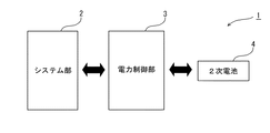
本発明は、2次電池により供給される電力によって動作する各種の電子・電気機器に対して広く適用することができる。そこで、以下では先ず、本発明の全体的な概略について、図1に示す電気機器1を参照しながら説明する。なお、図1は、2次電池を電源として用いる一般的な電気機器に対して本発明を適用した場合の一例を示すものであり、実現される機能毎に各部を模式的に示す機能ブロック図である。
【0023】
電気機器1は、図1に示すように、当該機器における主要な機能を実現するシステム部2と、このシステム部2の動作に必要となる電力の供給を制御する電力制御部3と、当該機器の電源として備えられた2次電池4とにより構成されている。
【0024】
システム部2は、2次電池4により供給される電力を消費することによって動作する各種のデバイスを備えている。このようなデバイスとしては、例えば、電気モータ、電熱器、各種半導体素子、各種電気・電子素子、アクチュエータ、或いはCRT(Cathode Ray Tube)や液晶パネルに代表される各種の表示装置などを挙げることができる。
【0025】
2次電池4は、充放電を繰り返し行うことが可能な電池であり、具体的には例えばLiイオン電池やNi−MH電池などである。なお、2次電池4に対して充電を行う際には、図示しない外部電源が2次電池4に接続され、この外部電源から2次電池4に対して電力が供給される。この充電操作は、2次電池4が電気機器1に搭載されたままの状態で行われるとしてもよいし、2次電池4が電気機器1に対して着脱自在とされ、電気機器1とは別の充電装置に装着された状態で行われるとしてもよい。
【0026】
一方、電力制御部3は、システム部2と2次電池4との間に配設され、2次電池4からシステム部2に対して供給する電力を制御する。電力制御部3は、例えば、各種の電気・電子素子や各種の半導体チップなどを組み合わせて構成されている。
【0027】
なお、電力制御部3における電力の制御手法としては、電子・電気回路やメカニカルなスイッチ等を用いて、いわばハードウェア的に実現されていてもよいし、半導体チップの動作を記述したソフトウェアプログラムによって、いわばソフトウェア的に実現されていてもよい。また、本例においては、システム部2とは別に設けられた電力制御部3により2次電池4から供給される電力を制御する構成としているが、例えば、2次電池4をシステム部2に直接接続し、システム部2で実行されるソフトウェアプログラムによって、本例における電力制御部3に相当する機能を実現する構成とすることもできる。
【0028】
また、電力制御部3は、2次電池4における電池セルの温度(セル温度)を検出する機構が備えられており、検出したセル温度が予め設定された所定の温度を超えた場合に、システム部2に対して、省電力モードに移行して動作することを要求する。
【0029】
2次電池4は、一般に、電池セルが劣化した状態で大電力放電を行うと、電池セルが過度に発熱し、電池セルが損傷し、以降の充放電が不能となってしまうという特徴を有している。したがって、電力制御部3は、特に2次電池4における電池セルの温度に基づいて電力供給を行うことによって、電池セルの異常な発熱を防止して、2次電池4の長寿命化を図ることが可能となる。また、電池本体や電子機器1の各部に、電池セルの過度の発熱に伴う変形や損傷が生じてしまうことを防止することができる。
【0030】
また、電子機器1におけるシステム部2は、必要となる分の電力を存分に消費して動作する通常動作モードと、この通常動作モード時よりも少ない電力で動作する省電力モードとを切り替え可能とされ、電力制御部3からの要求があった場合に通常動作モードから省電力モードに移行して動作することが可能とされている。ここで、省電力モードによる動作の具体的な例としては、例えば、システム部2に備えられた電気モータの回転数を通常動作モードよりも低くしたり、システム部2に備えられたデバイスのうちの一部を機能停止させたり、CPU等の半導体チップの動作クロックを低く設定することなどを挙げることができる。また、例えば、CPU等のデバイスを間欠動作させる(Throttleをかける)ことによって、このデバイスで消費される電力を低減させるとしてもよい。
【0031】
また、電子機器1においては、2次電池4における電池セルが過度に発熱してしまう以前に、電力制御部3がシステム部2に対して省電力モードへの移行を要求することができる。これにより、消費電力が低減されることから、結果として2次電池4における発熱が抑制され、この2次電池4はセル温度が次第に通常温度まで低下する。したがって、例えば、2次電池4がいわゆるインテリジェントバッテリーとされ、セル温度が異常な値を示した際に電力供給を遮断してしまう類のものであっても、この2次電池4からの電力供給が突然遮断されてしまうことを防止して、省電力モードで動作を継続することができる。これにより、2次電池4からの電力供給が突然完全に遮断されてしまうことによるユーザの不便を解消することができる。
【0032】
なお、電力制御部3は、システム部2を備える電子機器1の本体側に搭載されていてもよいし、2次電池4を備える電池部側に搭載され、2次電池4と電力制御部3とを備える電池部が電子機器1の本体に対して着脱自在とされていてもよい。
【0033】
つぎに以下では、上述した説明のさらに具体的な事例として、ノート型のパーソナルコンピュータ装置(以下、単にコンピュータ装置と称する。)に本発明を適用した場合における種々の実施の形態について順に説明する。なお、以下では、「2次電池からの電力供給が限界に達した」とする判断を、この2次電池の電池セルの温度に基づいて行う場合を例に挙げて説明することとする。
【0034】
<第1の実施の形態>
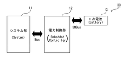
まず、第1の実施の形態として、図2に示すコンピュータ装置10について説明する。コンピュータ装置10は、図2に示すように、上述した電子機器1におけるシステム部2に相当するシステム部11と、電子機器1における電力制御部3に相当する電力制御部12と、電子機器1における2次電池4に相当する2次電池13とを備えて構成されている。
【0035】
システム部11は、例えば、CPU(Central Processing Unit)やいわゆるノースブリッジと称される信号受け渡し回路などにより構成される演算処理部14と、いわゆるサウスブリッジと称される信号受け渡し回路などにより構成される信号処理部15とが例えばPCI(Peripheral Component Interconnect)バス等のバスを介して接続されている。
【0036】
また、システム部11には、図示を省略するが、RAM(Random Access Memory)やROM(Read Only Memory)等の各種半導体メモリ、磁気ディスクに対して情報の記録再生を行うハードディスク装置、光ディスクに対して情報の記録再生を行う光ディスク装置などが備えられている。システム部11は、図示を省略するが、さらに、キーボードやマウス等の入力装置や液晶パネル等の表示装置、及び、これらの装置との間で信号の入出力を行う入出力インターフェースが備えられている。
【0037】
また、電力制御部12は、例えばバスを介して信号処理部15に接続されることにより、システム部11に接続されており、2次電池13からシステム部11に対して供給する電力を制御する。なお、本例においては、コンピュータ装置10に搭載された組込型制御チップ(EC:Embedded Controller)及びその周辺回路により電力制御部12としての機能が実現されているものとする。
【0038】
また、2次電池13は、例えばシステムマネジメントバス[SMBus(米国インテル社商標)]を介して電力制御部12と接続されており、コンピュータ装置10を構成する各部の動作に必要な電力を供給する電源として機能する。
【0039】
なお、コンピュータ装置10は、装置本体に搭載された2次電池13から供給される電力によってバッテリー駆動することが可能とされている一方で、外部AC電源が接続された場合には、このAC電源から供給される電力によっても動作することが可能とされている。
【0040】
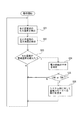
つぎに以下では、上述の如く構成されたコンピュータ装置10において実現される電力制御の実際について、電力制御部12の動作に着目して、図3に示すフローチャートを参照しながら説明する。
【0041】
電力制御部12は、例えば2次電池13が接続されたときに動作を開始し、図3に示すステップS11において、例えば電池側に設けられたセル温度検出機構との間で電気的な信号を授受することによって、2次電池13における電池セルの温度(セル温度)を検出する。
【0042】
次にステップS12において、電力制御部12は、ステップS11で検出されたセル温度が、予め設定された所定の温度(以下、警戒温度と称する。)を超えたか否かを判定する。この判定の結果、セル温度が警戒温度を超えた場合には処理をステップS13に進め、セル温度が警戒温度以下である場合にはステップS11以降の処理を繰り返し行う。
【0043】
ここで、電力制御部12は、図3に示す一連の処理を、他の処理とは独立して所定の時間間隔毎に繰り返し行い、2次電池の動作状態(本例ではセル温度)の検出を他の処理とは非同期で行っている。すなわち、本例においては、電力制御部12が2次電池13のセル温度の検出をポーリング(Polling)していることとなる。ただし、ステップS11におけるセル温度の検出は、電力制御部12によりポーリングすることに限定されるものではなく、2次電池13に備えられたセル温度の検出機構から所定の時間間隔でセル温度が電力制御部13に対して出力され、電力制御部13に現在のセル温度が入力された時点でステップS12の判定処理を行うとしてもよい。
【0044】
また、ステップS12における判定で用いる警戒温度の値は、例えば、電力制御部12としての機能を実現する組込型制御チップ内の所定のメモリ領域に予め記憶されていてもよいし、組込型制御チップの動作を記述したソフトウェアプログラムに直接書き込まれていてもよい。また、警戒温度の値は、変更不能な状態で記憶されていてもよいし、外部から適宜変更自在とされていてもよい。
【0045】
一方、ステップS13において、電力制御部12は、2次電池13のセル温度が警戒温度を超えた時点で、省電力モードへの移行条件を満足したとして、システム部11に対して省電力モードへの移行を要求する。この後、電力制御部12は、ステップS11に処理を戻して一連の処理を繰り返し行う。このとき、ステップS13において省電力モードへの移行要求を行う処理は、コンピュータ装置10が再度起動されるなどしてシステムがリセットされるまでの間に1回だけ行うとしてもよいし、2次電池13のセル温度が警戒温度以下となるまでの間、繰り返し行うとしてもよい。
【0046】
ここで、電力制御部12から出力される省電力モードへの移行要求の出力先としては、例えば、演算処理部14(CPU)で主として実行され、システム部11全体の処理を統括して制御するオペレーションシステム(OS:Operation System)、又は、このOS上で実行されるアプリケーション・プログラムや各種のユーティリティー・プログラムなどを挙げることができる。
【0047】
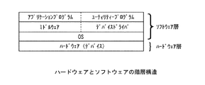
コンピュータ装置10においては、ハードウェアとソフトウェアとが図4に示すような階層構造で互いに連携して動作することにより、全体として機能するよう構成されている。すなわち、コンピュータ装置10は、CPUやメモリ等により構成された物理的な構造である演算処理部14及び信号処理部15、或いはハードディスク装置やキーボード等のデバイスからなるハードウェア層と、このハードウェア層の各部における動作を制御するソフトウェア層とにより構成されている。ソフトウェア層は、コンピュータ装置10の全体としての動作を統括制御するOS、各種デバイスを専用に制御する複数のデバイスドライバ、OSよりも高度で具体的な機能を提供するミドルウェア、これらOSやミドルウェア等により提供される機能を利用して具体的な機能をユーザに提供するアプリケーションプログラムやユーティリティープログラムなどにより構成されている。
【0048】
そこで、電力制御部12は、上述したOSに対して、或いは、OS上に常駐して実行され、2次電池13の状態を監視するユーティリティープログラムに対して、省電力モードへの移行を要求するメッセージを出力する。そして、このメッセージを受け取ったOSは、コンピュータ装置10のシステム全体を省電力モードへと移行させる。なお、このメッセージをユーティリティープログラムに対して出力する場合には、ユーティリティープログラムがメッセージを受け取った時点で、OSに対して省電力モードへの移行を要求し、OSがシステム全体を省電力モードへと移行させる。
【0049】
ここで、電力制御部12は、2次電池13から供給する電力の制御を行うために用意された専用のメッセージを出力することにより省電力モードへの移行を要求するとしてもよいが、例えば、省電力モードに移行するためのメッセージが予めOS等システム部11側に用意されている場合には、これと同等のメッセージを出力することにより省電力モードへの移行を要求すればよい。このように予め用意されたメッセージとしては、例えば、米国マイクロソフト社のOSであるWindows(登録商標)には、システムスリープ処理に移行するために所定のスキャンコード(E05F)を挙げることができる。また、例えば、ユーザがコンピュータ装置10に設けられた電源ボタンやスリープボタンを操作するによって省電力モードへの移行を要求したときに発生するメッセージと同等なメッセージを出力するとしてもよい。
【0050】
ここで、省電力モードとしては、通常の動作時よりも消費電力が低い動作モードであれば特に限定されるものではないが、一例として、いわゆるスタンバイ状態やハイバーネート状態に移行することを挙げることができる。
【0051】
スタンバイ状態とは、コンピュータ装置10を構成する各部のうち、例えばCPUやハードディスク装置、或いは表示装置などのように、比較的消費電力が大きなデバイスの動作を停止したり、動作速度などを意図的に低下させることなどによって通常時よりも低い消費電力で動作する状態である。このスタンバイ状態から通常状態への復帰は、例えば以下のようにして行われる。すなわち、例えばユーザがキーボードやマウスを操作したり電源ボタンを押下することなどにより、復帰イベントが発生すると、組込型制御チップ(EC)がこの復帰イベントを検知し、システム部11に対してスタンバイ状態からの復帰を要求する。そしてシステム部11で実行されているオペレーションシステム(OS)が各デバイスに対して動作状態の復帰を指示するメッセージを送出し、これにより各デバイスが通常状態に復帰する。
【0052】
また、ハイバーネート(Hibernate)状態とは、コンピュータ装置10のメモリ領域に存在するデータや、現在の作業環境を再現するために必要となる情報などをハードディスク装置などの不揮発性記憶手段に書き出し、待機電力等のような最低限必要となる電力以外を全て遮断する状態である。ハイバーネート状態から通常状態への復帰は、コンピュータ装置10の各部に対して電力を供給した後に、ハードディスク装置などに書き出したデータや情報を読み出して、以前の作業状態を再現することにより行われる。このハイバーネート状態においては、電力をほぼ全て遮断することから、スタンバイ状態よりもさらに消費電力を低減することができる。なお、ハイバーネート状態は、一般に、サスペンド状態、休眠状態、或いは休止状態とも称されている。
【0053】
なお、省電力モードに移行するに際しては、上述のように、システム全体をスタンバイ状態やハイバーネート状態へ移行することに限定されるものではなく、例えばCPUの動作クロックを低減したり、表示装置として備えられる液晶パネルのバックライトにおける輝度を低減させるなどのように、各デバイスを個別に省電力モードへ移行させるとしてもよい。
【0054】
コンピュータ装置10においては、電力制御部12が上述の如く動作することにより、2次電池13における電池セルが警戒温度を超えた場合に、省電力モードに移行し、消費電力を低減することができる。このため、2次電池13における発熱が抑制され、この2次電池13はセル温度が次第に通常温度まで低下する。したがって、2次電池13におけるセル温度の異常な発熱に伴う電池セルの劣化を防止して、2次電池13の長寿命化を図ることができるとともに、発熱に伴って、コンピュータ装置10の各部に変形が生じたり、ユーザがやけどを追ってしまう事故などを防止することができる。
【0055】
また、例えば、2次電池13がいわゆるインテリジェントバッテリーとされ、セル温度が異常な値を示した際に電力供給を遮断してしまう類のものであっても、「異常な値」としてインテリジェントバッテリー側で規定された温度よりも低い温度を電力制御部12における「警戒温度」として設定しておくことにより、おこのインテリジェントバッテリーにおける電力遮断動作を防止することができる。したがって、電力供給が突然遮断されてしまうことにより生じるデータ損失を防止することができる。
【0056】
なお、コンピュータ装置10においては、電力制御部12から省電力モードへの移行要求がなされた時点で即座に省電力モードへ移行するとしてもよいが、例えばCRTや液晶パネルにより構成された表示装置の画面上に、所定のメッセージやアイコンなどを表示することにより、省電力モードに移行することをユーザに対して通知することが望ましい。これにより、例えば、ユーザに対して必要な操作を早急に終わらせることを促したり、外部AC電源を接続するように促すことができる。
【0057】
上述のようなユーザに対する通知処理は、オペレーションシステム(OS)により実現されていてもよいし、このOS上で実行処理されて、電力の制御に関する情報をユーザに対して通知する機能に特化した専用のユーティリティー・プログラムにより実現されていてもよい。
【0058】
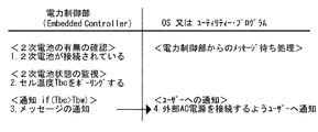
このような通知処理は、例えば、図5に示す手順により実現される。図5に示すように、電力制御部12は、2次電池13が接続されているか否かを判定した後、接続されている場合には、この2次電池13のセル温度Tbcを随時検出(ポーリング)する。そして、セル温度Tbcが予め設定された警戒温度Tbwを超えた場合に、電力制御部12は、OS又はユーティリティー・プログラムに対して、この旨を示すメッセージや信号を出力する。
【0059】
一方、OS又はユーティリティー・プログラムの動作としては、図5に示すように、電力制御部12から出力された上記のメッセージを待機した状態において、このメッセージを受信すると、セル温度Tbcが予め設定された警戒温度Tbwを超えたことをユーザに通知するウィンドウを表示装置の画面上に表示する。このとき表示するウィンドウには、例えば「外部AC電源を接続して下さい」又は「電池の温度が上昇しています」などのメッセージを表示すればよい。
【0060】
なお、ユーザに対して通知を行う手法としては、表示装置の画面上にメッセージやアイコンなどを表示することに限定されるものではなく、例えば音声を出力したり、専用に設けられたインジケータを点灯させるなどして通知を行うとしてもよい。
【0061】
また、本例においては、電池制御部12によって2次電池13のセル温度Tbcが警戒温度Tbwを超えているか否かを判定するとして説明したが、このような判定は電池制御部12で行うことに限定されるものではなく、例えばOSや、このOS上で実行されるユーティリティー・プログラム等のソフトウェア・プログラムによって実現してもよい。この場合に、電池制御部12は、2次電池13のセル温度Tbcを、判定を行うプログラムに対して受け渡す機能を有していればよい。また、この場合には、所定の時間間隔でセル温度Tbcを電池制御部12からプログラムに送出するとしてもよいし、プログラムからの要求がなされる毎に、電池制御部12からプログラム側に現在のセル温度Tbcを受け渡すとしてもよい。
【0062】
また、上述の説明においては、2次電池13のセル温度Tbcが予め設定された所定の警戒温度Tbwを超えた場合に、省電力モードへの移行要求や、ユーザに対する通知を行うとしたが、警戒温度を予め段階的に複数設定しておくこともできる。
【0063】
この場合には、例えば、セル温度Tbcが第1の警戒温度Tbw1を超えた時点で、表示装置の画面上に「電池の温度が上昇しています」等のメッセージを表示することによりユーザに対して注意を促す。また、第1の警戒温度Tbw1よりも高い第2の警戒温度Tbw2をセル温度Tbcが超えた時点で、表示装置の画面上に「外部AC電源を接続して下さい」等のメッセージを表示することにより、ユーザに対してAC電源の接続を要求し、第2の警戒温度Tbw2よりも高い第3の警戒温度Tbw3をセル温度Tbcが超えた時点で、コンピュータ装置10のシステムを省電力モードに移行させる。
【0064】
コンピュータ装置10においては、上述の如く、警戒温度を段階的に複数設定しておき、セル温度Tbcが各警戒温度を超えた時点でそれぞれ異なる動作を行う構成とすることにより、例えば、省電力モードへの移行が間近であることを段階的にユーザに対して通知することができ、ユーザの利便性を向上させることができる。
【0065】
ところで、近年のノート型パソコンは、平均消費電力と比較して、ピーク時における消費電力が非常に高いという特徴がみられる。したがって、ピーク時の電力消費を十分に満足する放電特性を有する2次電池を搭載することが求められるが、特にノート型パソコンの場合には、小型軽量であることが大きな商品価値を有することからセット体積に限界があり、十分な放電特性を有する2次電池を搭載することが困難な場合がある。
【0066】
しかしながら、上述したコンピュータ装置10においては、電力制御部12を備えていることから、通常使用時の消費電力に対応する程度の放電特性を有する2次電池を搭載した場合であっても、消費電力のピーク時に、電力制御部12が機能することにより、自動的にシステム全体の消費電力を低減させることができる。すなわち、電力制御部12がいわば安全機構として機能することから、通常使用時の消費電力に対応した小型軽量な2次電池を搭載した場合であっても、電力消費のピーク時に2次電池が異常に発熱したり、電力供給が突然遮断されることによりデータが損失する虞を防止することができる。したがって、全体として小型で軽量なノート型パソコンを実現することが可能となる。
【0067】
<第2の実施の形態>
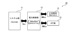
つぎに、第2の実施の形態として、図6に示すコンピュータ装置20について説明する。コンピュータ装置20は、上述した第1の実施例におけるコンピュータ装置10と比較して、図6に示すように、電力制御部12にATF部21が接続されている点で大きく異なり、他の各部は、コンピュータ装置10と同一又は同等の構成とされている。そこで、本例においては、上述した第1の実施の形態と同一又は同等な部位についての説明を省略し、図中において同一の符号を付すこととする。
【0068】
なお、後述で例示して説明する各実施の形態についても、特別に記述する点を除いて、上述した第1の実施の形態におけるコンピュータ装置10と同一又は同様な構成とすることができることから、各実施の形態の説明においては第1の実施の形態と同一又は同等な部位についての説明を省略し、図中において同一の符号を付すこととする。
【0069】
コンピュータ装置20に備えられるATF(Active Thermal Feedback)部21は、システムマネジメントバス(SMBus)を介して電力制御部12に接続されており、システム部11に配設されたCPUの温度を監視する機能を有するデバイスである。ATF部21は、CPUの温度を検出して、この温度を電力制御部12に対して通知する。
【0070】
本例において、コンピュータ装置20は、米国インテル社、米国マイクロソフト社、及び株式会社東芝などにより共同で策定されているACPI(Advanced Configuration & Power Interface)と称される規格に沿って基本構造が設計されたものと想定する。ACPIでは、CPUの温度が予め設定された警戒温度に達した際に、自身の発熱によってCPUが損傷してしまうことを防止するために、CPUの動作クロックを低下させるなどして消費電力を低下させる機構が実装されている。
【0071】
本例においては、2次電池13のセル温度が所定の温度を超えた場合に、電力制御部12が上述したACPIの機構を利用してCPUの消費電力を低下させることにより、2次電池13の異常な温度上昇を防止するように構成されている。より具体的には、以下で説明するように、2次電池13のセル温度を監視する処理と、ACPI規格に基づいてCPUの温度を監視する処理とを電力制御部12が並行して行うことにより実現されている。
【0072】
すなわち、2次電池13のセル温度を監視する一連の処理として、電力制御部12は、2次電池13が接続されているか否かを確認し、接続されている場合には、この2次電池13のセル温度Tbcを非同期処理にて検出(ポーリング)する。そして、検出されたセル温度Tbcが予め設定された所定の警戒温度Tbwを超えた場合に、この旨を示す所定のフラグを立てる。また、警戒温度Tbwを下回る場合には、フラグを解除する。このようなフラグは、例えば、電力制御部12に備えられた半導体メモリ内の所定のアドレスにあるビットを反転させることなどにより実現すればよい。
【0073】
一方、2次電池のCPU温度を監視する一連の処理として、電力制御部12は、ATF部21により検出されたCPU温度Tccが予め設定された所定の温度(警戒温度)Tcwを超えた場合に、CPUの動作クロックを低減させる要求をシステム部11に対して出力し、CPU温度Tccが予め設定された所定の温度(シャットダウン温度)Tceを超えた場合に、システム部11に対して機能停止(シャットダウン)動作を行う要求をシステム部11に対して出力する。また、電力制御部12は、上述のセル温度を監視する一連の処理で用いられるフラグを参照し、このフラグが立っていて且つTcc<Tceである場合には、CPU温度の値Tccを、Tcw<Tcc<Tceを満足する値に設定し直す。
【0074】
すなわち本例においては、2次電池13のセル温度が警戒温度を超えた場合に、電力制御部12によって、CPU温度が警戒温度を超えたと偽った要求をシステム部11に対して出力することにより、CPUにおける消費電力を低減させる構成とされている。このようにCPUにおける消費電力が低減すると、2次電池13から放電される電力も低下することから、この2次電池13における発熱が抑制されることとなる。
【0075】
本例のように、例えばACPIにより実現される消費電力の制御機構を備えるコンピュータ装置20においては、2次電池13のセル温度が警戒温度Tbwを超えた場合に、ACPIの機能を利用してコンピュータ装置20全体の消費電力を低減する構成とすることにより、省電力モードへの移行機構を新たに設ける必要がなく、2次電池13の異常な発熱や突然の電力供給の停止を効果的に防止することが可能なシステムを低コストにて実現することができる。
【0076】
<第3の実施の形態>
つぎに、第3の実施の形態として、図7に示すコンピュータ装置30について説明する。コンピュータ装置30は、図7に示すように、第1の実施の形態として示したコンピュータ装置10と同様な装置構成とされている。
【0077】
本例において、コンピュータ装置30は、第2の実施の形態で説明したACPI規格に沿って基本構造が設計されたものと想定する。このコンピュータ装置30は、2次電池13の電力残量が低下した際に、省電力モードに移行させる機構が備えられているものとする。このような機構は、近年利用されている多くのコンピュータ装置に搭載されており、システム部11に備えられたBIOS(Basic Input Output System)及びオペレーションシステム(OS)が対応していることが前提となる。
【0078】
本例においては、電力制御部12が偽って報告する対象が、CPUの温度ではなくて、2次電池13の電力残量である点が、第2の実施の形態で説明したコンピュータ装置20との相違点である。
【0079】
コンピュータ装置30は、電力制御部12において、コンピュータ装置20の場合と同様な2次電池13のセル温度を監視する処理と、ACPI規格に基づいて2次電池13の電力残量を監視する処理とが並行して行われる。
【0080】
2次電池の電力残量を監視する一連の処理として、電力制御部12は、所定の時間が経過する毎に2次電池13の電力残量を検出し、予め規定された所定のメモリ領域に電力残量を示す値Cを書き込む。
【0081】
一方、システム部11は、この値Cを随時参照しており、予め設定された警戒残量Cwを下回った場合に、スタンバイ状態又はハイバーネート状態などの省電力モードに移行する。
【0082】
また、電力制御部12は、2次電池13のセル温度を監視する処理で用いられたフラグを参照し、このフラグが立っている場合には、本来の電池残量の値Cではなく、C'<Cwとなる値C'を所定のメモリ領域に書き込む。
【0083】
すなわち、本例においては、2次電池13のセル温度Tbcが所定の警戒温度Tbwを超えた場合に、電池残量の値Cを電力制御部12が意図的に偽ることにより、システム部11に対して省電力モードへの移行を要求する構成とされている。
【0084】
本例のように、2次電池13の電力残量に応じてシステムを省電力モードに移行させる機構がコンピュータ装置30に備わっている場合には、電力制御部12が電池残量を偽ってシステムに報告することにより、2次電池12におけるセル温度の異常な発熱を防止する構成とすることができる。これにより、従来から用いられているBIOSやOSなどに対して新たな変更を加えることなく、本発明を極めて低コストで効果的に適用することができる。
【0085】
なお、本例に関する上述の説明においては、電池残量の値Cを偽るデバイスが電力制御部12であるとしたが、例えば2次電池13がインテリジェントバッテリーとして構成されている場合には、セル温度Tbcが警戒温度Tbwを超えた場合に電池残量の値Cを偽って報告する機構を、このインテリジェントバッテリー側に搭載された制御回路に組み込むこともできる。この場合には、コンピュータ装置30の本体側を、ACPIに対応した従来のコンピュータ装置と同等の構成とすることができ、インテリジェントバッテリーの制御回路以外の部分には改変を加える必要がないという利点を有する。
【0086】
<第4の実施の形態>
つぎに、第4の実施の形態として、図8に示すコンピュータ装置40について説明する。コンピュータ装置40は、図8に示すように、複数の2次電池が搭載され、これら複数の2次電池13が電池切替部41を介して電力制御部12に接続されている点で、第1の実施の形態として示したコンピュータ装置10とは異なる装置構成とされている。なお、本例においては、コンピュータ装置40に第1の2次電池13aと第2の2次電池13bとの2つの2次電池が搭載された場合を想定するが、コンピュータ装置40に搭載する2次電池の数については特に制限されるものではない。
【0087】
コンピュータ装置40においては、各2次電池13と電池切替部41との間、及び電池切替部41と電力制御部12との間が、それぞれシステムマネジメントバス(SMBus)により接続されている。電池切替部41は、電力制御部12からの要求に応じて、第1の2次電池13aと第2の2次電池13bとのうちから、システム部11に対する電力供給に用いる電池を切り替える機能を具備している。
【0088】
また、電力制御部12は、第1の2次電池13aのセル温度Tbc1と第2の2次電池13bのセル温度Tbc2とを検出するとともに、各々の電池の電力残量を検出する。そして、電力制御部12は、各2次電池13のセル温度と電力残量とに基づいて、各2次電池からの電力供給を制御する。
【0089】
ここで、電力制御部12における電力制御処理のうち、セル温度が警戒温度を超えた場合の処理に注目し、この処理の一例について、図9に示すフローチャートを参照しながら説明する。
【0090】
電力制御部12は、第1又は第2の2次電池13a,13bが接続されることにより動作を開始し、図9に示すステップS21において、第1の2次電池13aのセル温度Tbc1及び第2の2次電池13bのセル温度Tbc2をそれぞれ検出する。次にステップS22において、電力制御部12は、第1の2次電池13aの電力残量C1及び第2の2次電池13nの電力残量C2を検出する。このとき、電力残量を検出する手法としては、例えば電池側に設けられた電力残量検出機構との間で電気的な信号を授受することによって行うとすればよい。
【0091】
次にステップS23において、電力制御部12は、ステップS11で検出された各2次電池13のセル温度Tbc1,Tbc2が警戒温度Tbwを超えたか否かを判定する。この判定の結果、セル温度が警戒温度を超えた場合には処理をステップS24に進め、いずれのセル温度も警戒温度以下である場合にはステップS21以降の処理を繰り返し行う。
【0092】
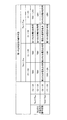
ステップS24において、電力制御部12は、図10に示す判定表を参照し、、各2次電池13の動作状態(セル温度と電力残量)に応じて、各2次電池13からの電力供給が可能であるか否かを判定する処理を行う。すなわち、各2次電池13のセル温度Tbc1,Tbc2がそれぞれ警戒温度Tbwを超えているか否かという条件と、各2次電池13の電力残量C1,C2がそれぞれ、当該2次電池からのさらなる電力の供給が困難となる限界残量C0を下回っているか否かという条件との2つの条件に基づいた判定処理を行う。
【0093】
ここで、ステップS24における判定処理について、図10に示す判定表を参照しながら具体的に説明する。
【0094】
第1の2次電池13aのセル温度Tbc1が警戒温度Tbwを下回っており、且つ、電力残量C1が限界残量C0を上回っているときに、第2の2次電池13bのセル温度Tbc2が警戒温度Tbwを超えている場合、又は第2の2次電池13bの電池残量C2が限界残量C0を下回っている場合には、第1の2次電池13aから電力供給を行う。
【0095】
第2の2次電池13bのセル温度Tbc2が警戒温度Tbwを下回っており、且つ、電力残量C2が限界残量C0を上回っているときに、第1の2次電池13aのセル温度Tbc1が警戒温度Tbwを超えている場合、又は第1の2次電池13aの電池残量C1が限界残量C0を下回っている場合には、第2の2次電池13bから電力供給を行う。
【0096】
なお、この判定処理で、現在電力供給を行っている電池とは異なる電池から電力供給を行うとする結果が得られた場合には、電力制御部12が電池切替部41に対して、使用する電池を切り替えることを要求する。また、現在電力供給を行っている電池と同じ電池から電力供給を行うとする結果が得られた場合には、電力制御部12は特に制御処理を行わず、現在の電力供給を行っている電池からの電力供給を維持する。
【0097】
また、第1の2次電池13a及び第2の2次電池13bのいずれも十分に電力供給を行うことが可能な状態である場合、すなわち、Tbc1<Tbw、C1>C0、Tbc2<Tbw、及びC2>C0なる4つの条件を満足する場合には、電力制御部12は特に制御処理を行わず、現在の電力供給を行っている電池からの電力供給を維持する。
【0098】
さらに、上述した結果以外の場合、すなわち、図10中において「TBH」及び「LBH」として示す場合には、第1の2次電池13a及び第2の2次電池13bの双方が共に、さらなる電力供給に限界が生じており、コンピュータ装置40を省電力モードに移行させる必要があることを示している。これらの場合については、ステップS25以降で説明する。
【0099】
上述したステップS24での判定処理の後に、ステップS25において電力制御部12は、この判定結果が「TBH」又は「LBH」であるか否かを判断する。そして、判定結果が「TBH」又は「LBH」のいずれでもない場合には、ステップS24の判定結果に応じた動作を行うとともに、処理をステップS20又はステップS21に戻し、上述した一連の処理を繰り返す。また、判定結果が「TBH」又は「LBH」である場合には、処理をステップS26に進める。
【0100】
ステップS26において、電力制御部12は、省電力モードへの移行条件を満足したとして、システム部11に対して省電力モードへの移行を要求する。この後、電力制御部12は、ステップS21に処理を戻して一連の処理を繰り返し行う。このステップS26における処理は、図3におけるステップS13における処理と同等なものであり、この処理が行われることによって、コンピュータ装置40は省電力モードへ移行することとなる。
【0101】
以上で説明したように、本例においては、各2次電池13のセル温度と電力残量との2つの条件に基づいて、実際に電力供給を行う電池を選択的に用いると同時に、いずれの2次電池からも電力供給が困難となった場合にシステムを省電力モードに移行させるという制御が電力制御部12により実現されている。
【0102】
これにより、例えば、第1の2次電池13aと第2の2次電池13bとの双方に十分な電力残量がある状況で、現在電力供給を行っている2次電池のセル温度が上昇した場合であっても、他の2次電池に切り替えて電力供給を継続しつつ、元の2次電池の異常な発熱を防止することができる。また、元の2次電池が十分に冷却された際には、この2次電池を再び利用して電力供給を行うことができる。
【0103】
これに対して、例えば従来のインテリジェントバッテリーにおいては、2次電池の電力残量とセル温度とのうちのいずれか一方が2次電池の放電停止条件を満足した時点で、即座に電力供給が遮断されてしまう。このため、たとえ2次電池に電力残量に余裕があっても、セル温度が規定の温度に達した時点で、以後の電力供給を継続することができない。
【0104】
したがって、本例に係るコンピュータ装置40は、従来よりも効率的に2次電池13に蓄えられた電力を利用することが可能であり、2次電池13による駆動を長時間化することができるといった利点を有している。
【0105】
<他の実施の形態>
なお、上述においては、ノート型パソコンとして構成されたコンピュータ装置に対して本発明を適用した場合の実施の形態について説明したが、本発明は、2次電池により供給される電力によって動作する各種の電子・電気機器に対して広く適用可能である。具体的には例えば、携帯型電話機、PDA(Persnal Digital Assistant)機器と称される情報端末装置、各種の音声データを再生する携帯型の音声再生機器、或いはデジタルビデオカメラに代表される各種の撮像装置に対しても適用することができる。
【0106】
また、上述した電力制御部3或いは電力制御部12における電力制御動作は、所望の電子機器で実行処理させるソフトウェアプログラムとして構成することができる。また、このようなソフトウェアプログラムを各種の記録媒体に格納して提供するとしてもよい。
【0107】
【発明の効果】
本発明によれば、2次電池により供給される電力によって動作する機器において、2次電池における異常な発熱に伴う電池寿命の劣化や各部の損傷などを防止することができるとともに、電力供給が突然遮断されてしまうことによるユーザの不便を解消することができる。
【0108】
したがって、例えば、電力供給が突然遮断されてしまうことを起因とするデータの損失や、機器の損傷・故障を防止することができ、2次電池を利用して動作する機器や情報処理装置の信頼性と利便性とを向上させることができる。
【図面の簡単な説明】
【図1】本発明の概略について説明するためのブロック図である。
【図2】本発明の第1の実施の形態として示すコンピュータ装置のシステムブロック図である。
【図3】同コンピュータ装置における電力制御処理の一例を示すフローチャートである。
【図4】同コンピュータ装置におけるハードウェアとソフトウェアとの階層構造について説明するための模式図である。
【図5】同コンピュータ装置におけるユーザに対する通知処理について説明するための模式図である。
【図6】本発明の第2の実施の形態として示すコンピュータ装置のシステムブロック図である。
【図7】本発明の第3の実施の形態として示すコンピュータ装置のシステムブロック図である。
【図8】本発明の第4の実施の形態として示すコンピュータ装置のシステムブロック図である。
【図9】同コンピュータ装置における電力制御処理の一例を示すフローチャートである。
【図10】同コンピュータ装置における電力制御の判定処理について説明するための図であり、2つ具備された2次電池の動作状態に応じて行う処理についてまとめた表である。
【符号の説明】
1 電子機器、2 システム部、3 電力制御部、4 2次電池、10 コンピュータ装置、11 システム部、12 電力制御部、13 2次電池、13a第1の2次電池、13b 第2の2次電池、14 演算処理部、15 信号処理部、20 コンピュータ装置、21 ATF部、30 コンピュータ装置、40 コンピュータ装置[0001]
[Field of the Invention]
The present inventionThe present invention relates to an information processing apparatus that operates with electric power supplied from a secondary battery.
[0002]
[Prior art]
In recent years, semiconductor manufacturing technology and miniaturized packaging technology have been rapidly developed, and along with this, various electronic and electrical devices have been dramatically reduced in size and weight. Examples of such devices include mobile phones, information terminal devices called PDA (Persnal Digital Assistant) devices, and various computer devices. Further, miniaturization and weight reduction have been promoted remarkably in portable audio reproduction devices that reproduce various audio data and various imaging devices represented by digital video cameras.
[0003]
In the electronic / electrical equipment as described above, a secondary battery (battery) is generally mounted as a power source, assuming that it is used outdoors or the like due to a reduction in size and weight. Such secondary batteries are required to be small and light and have a large capacity. For example, Li ion batteries and Ni-MH batteries are used.
[0004]
By the way, in the electronic / electrical equipment as described above, in particular, a notebook personal computer, it is required that the battery can be driven for a longer time, so that the capacity and function of the secondary battery can be increased. Technological development is progressing rapidly.
[0005]
Here, as an example of enhancement of function, a battery module itself having a control circuit configured by a CPU or the like, which is generally called an intelligent battery, has been proposed. In intelligent batteries, accurate remaining capacity calculation and detailed power consumption control can be performed by performing power supply and charging operations while monitoring the state of the secondary battery (battery remaining state, charge / discharge state, etc.). It is possible.
[0006]
[Problems to be solved by the invention]
By the way, in general, in a secondary battery, when high power discharge is performed when the battery cell deteriorates, the battery cell generates heat, and it is difficult to continue normal power supply. On the other hand, the above-described intelligent battery is provided with a mechanism for stopping the power supply from the secondary battery when the temperature of the battery cell exceeds a preset temperature, which occurs in the conventional secondary battery. It is possible to prevent abnormal heat generation of the battery cell that may have occurred.
[0007]
However, for example, when the power supply stop mechanism as described above operates in an intelligent battery mounted on a computer device, the power supply is suddenly cut off, so that the content stored in the memory is lost or the signal of the hard disk device is lost. There is a problem that data loss occurs due to damage to the recording surface.
[0008]
Further, not only computer devices but also various electronic / electrical devices as listed above, if the power supply is suddenly cut off, the convenience of the user may be impaired, or serious damage may occur. There are many cases.
[0009]
Therefore, the present invention has been made in view of the above-described conventional situation, and prevents sudden interruption of power supply from a secondary battery in a device that operates with power supplied from the secondary battery. It is an object of the present invention to provide a power control apparatus and a power control method that can be used. It is another object of the present invention to provide an information processing apparatus and a power control program capable of preventing data loss caused by sudden interruption of power supply from a secondary battery.
[0013]
[Means for Solving the Problems]
The present inventionClaims1The information processing apparatus according to the present invention is an information processing apparatus that operates by power supplied from a secondary battery, and monitoring means that monitors the temperature of the battery cell in the secondary battery;When the temperature of a CPU (Central Processing Unit) disposed in the information processing apparatus exceeds a predetermined value, or the remaining power of the secondary battery is lower than a predetermined valueThe information processing apparatus is shifted to a power saving mode.Transition meansAnd when the temperature of the battery cell monitored by the monitoring means exceeds a predetermined threshold value,When the transition means shifts the information processing apparatus to the power saving mode when the temperature of the CPU exceeds a predetermined value, the CPU temperature exceeding the predetermined value is changed to the original temperature value of the CPU. When the transition means shifts the information processing apparatus to the power saving mode when the remaining power of the secondary battery is lower than a predetermined value, the original remaining power of the secondary battery Is replaced with a value of the remaining electric power that is lower than the predetermined value, thereby causing the transition means to shift to the power saving mode of the information processing apparatus.And a control means.
[0014]
According to the present invention configured as described above, it is possible to prevent the deterioration of the battery life and the damage of each part due to the abnormal heat generation in the secondary battery. In addition, since the power supply is suddenly cut off, it is possible to solve problems such as loss of working data and damage to the signal recording surface of the hard disk device.
[0015]
Note that the information processing apparatus preferably further includes operation mode transition notifying means for notifying the user of the fact when the power control unit requests the transition to the power saving mode. Thereby, the information processing apparatus can notify the user of shifting to the power saving mode. As such operation mode transition notifying means, specifically, various display devices such as CRT (Cathode Ray Tube), liquid crystal panel, or PDP (Plasma Display Panel), and interfaces for driving these various display devices are used. A circuit, an arithmetic processing circuit that generates data to be displayed on a screen of a display device, an image processing circuit, and the like can be given. Note that the method of notifying the user is not limited to displaying a message or icon on the screen of the display device. For example, a voice is output or a dedicated indicator is turned on. Notification may be performed by, for example.
[0016]
Also,Information processing apparatusAs a specific example in the case of shifting to the power saving mode, the operation program executed in the information processing apparatus may be requested to shift to the standby state or hibernate state. Here, the standby state refers to, for example, a RAM (Random Access Memory) in which various types of data are stored by stopping power supply to a device that consumes a lot of power such as a display device or a hard disk device. A state in which the device operates in a mode in which a minimum amount of power is supplied only to devices necessary for resuming work. The hibernate state refers to all devices except circuits that are minimally necessary after temporarily writing data necessary for resuming work stored in a volatile memory to a storage device such as a hard disk device. This means that the power supply to is stopped.
[0017]
Also,Information processing apparatusIf the further power supply from the secondary battery to which power is currently supplied has reached its limit, and there are other secondary batteries that can supply power, The supply may be switched to supply from a secondary battery capable of supplying the power. As a result, when the information processing apparatus includes a plurality of secondary batteries, power is supplied from another available secondary battery even after the power supply from one secondary battery reaches the limit. The operation can be continued.
[0021]
DETAILED DESCRIPTION OF THE INVENTION
Hereinafter, embodiments of the present invention will be described in detail with reference to the drawings.
[0022]
The present invention can be widely applied to various electronic / electrical devices that operate with electric power supplied from a secondary battery. In the following, first, an overall outline of the present invention will be described with reference to the electric device 1 shown in FIG. FIG. 1 shows an example in which the present invention is applied to a general electric device using a secondary battery as a power source, and is a functional block diagram schematically showing each part for each realized function. It is.
[0023]
As shown in FIG. 1, the electrical device 1 includes a
[0024]
The
[0025]
The secondary battery 4 is a battery that can be repeatedly charged and discharged, and specifically, for example, a Li ion battery or a Ni-MH battery. When charging the secondary battery 4, an external power source (not shown) is connected to the secondary battery 4, and power is supplied from the external power source to the secondary battery 4. This charging operation may be performed in a state where the secondary battery 4 is mounted on the electric device 1. The secondary battery 4 is detachable from the electric device 1, and is separate from the electric device 1. It may be performed in a state of being mounted on the charging device.
[0026]
On the other hand, the power control unit 3 is disposed between the
[0027]
The power control method in the power control unit 3 may be realized as hardware using electronic / electrical circuits, mechanical switches, or the like, or by a software program describing the operation of the semiconductor chip. In other words, it may be realized as software. In this example, the power supplied from the secondary battery 4 is controlled by the power control unit 3 provided separately from the
[0028]
In addition, the power control unit 3 is provided with a mechanism for detecting the temperature of the battery cell (cell temperature) in the secondary battery 4, and when the detected cell temperature exceeds a predetermined temperature, the system The
[0029]
In general, the secondary battery 4 is characterized in that if high-power discharge is performed in a state where the battery cell is deteriorated, the battery cell excessively generates heat, the battery cell is damaged, and subsequent charging / discharging becomes impossible. is doing. Therefore, the power control unit 3 prevents the abnormal heat generation of the battery cell and extends the life of the secondary battery 4 by supplying power based on the temperature of the battery cell in the secondary battery 4 in particular. Is possible. Moreover, it can prevent that the deformation | transformation and damage accompanying the excessive heat_generation | fever of a battery cell arise in each part of a battery main body or the electronic device 1. FIG.
[0030]
In addition, the
[0031]
In the electronic device 1, the power control unit 3 can request the
[0032]
The power control unit 3 may be mounted on the main body side of the electronic device 1 including the
[0033]
Next, as a more specific example of the above description, various embodiments in the case where the present invention is applied to a notebook personal computer device (hereinafter simply referred to as a computer device) will be described in order. In the following, a case where the determination that “the power supply from the secondary battery has reached the limit” is performed based on the temperature of the battery cell of the secondary battery will be described as an example.
[0034]
<First Embodiment>
First, a
[0035]
The
[0036]
Although not shown, the
[0037]
The
[0038]
Further, the
[0039]
The
[0040]
Next, the actual power control realized in the
[0041]
The
[0042]
Next, in step S12, the
[0043]
Here, the
[0044]
Moreover, the value of the warning temperature used in the determination in step S12 may be stored in advance in a predetermined memory area in the embedded control chip that realizes the function as the
[0045]
On the other hand, in step S13, when the cell temperature of the
[0046]
Here, as an output destination of the request for shifting to the power saving mode output from the
[0047]
The
[0048]
Therefore, the
[0049]
Here, the
[0050]
Here, the power saving mode is not particularly limited as long as it is an operation mode in which power consumption is lower than that in a normal operation, but as an example, a transition to a so-called standby state or hibernate state can be mentioned. it can.
[0051]
The standby state is intended to stop the operation of a device with relatively large power consumption, such as a CPU, a hard disk device, or a display device among the components constituting the
[0052]
The hibernate state means that data existing in the memory area of the
[0053]
As described above, the transition to the power saving mode is not limited to the transition of the entire system to the standby state or the hibernate state. For example, the operation clock of the CPU is reduced or the display device is provided. Each device may be individually shifted to the power saving mode so as to reduce the luminance of the backlight of the liquid crystal panel.
[0054]
In the
[0055]
In addition, for example, even if the
[0056]
The
[0057]
The notification process for the user as described above may be realized by an operation system (OS), or is executed on the OS and specialized in a function for notifying the user of information related to power control. It may be realized by a dedicated utility program.
[0058]
Such notification processing is realized, for example, by the procedure shown in FIG. As shown in FIG. 5, after determining whether or not the
[0059]
On the other hand, as the operation of the OS or utility program, as shown in FIG. 5, when this message is received while waiting for the above message output from the
[0060]
Note that the method of notifying the user is not limited to displaying a message or icon on the screen of the display device. For example, a voice is output or a dedicated indicator is turned on. Notification may be performed by, for example.
[0061]
Further, in this example, the
[0062]
Further, in the above description, when the cell temperature Tbc of the
[0063]
In this case, for example, when the cell temperature Tbc exceeds the first warning temperature Tbw1, a message such as “the battery temperature is rising” is displayed on the screen of the display device to the user. Call attention. In addition, when the cell temperature Tbc exceeds the second warning temperature Tbw2 higher than the first warning temperature Tbw1, a message such as “Please connect an external AC power supply” is displayed on the screen of the display device. To request the user to connect an AC power supply, and when the cell temperature Tbc exceeds the third warning temperature Tbw3 higher than the second warning temperature Tbw2, the system of the
[0064]
In the
[0065]
By the way, recent notebook personal computers are characterized by very high power consumption at peak times compared to average power consumption. Accordingly, it is required to mount a secondary battery having a discharge characteristic that sufficiently satisfies the power consumption at the peak time. However, particularly in the case of a notebook personal computer, small size and light weight have great commercial value. The set volume is limited, and it may be difficult to mount a secondary battery having sufficient discharge characteristics.
[0066]
However, since the
[0067]
<Second Embodiment>
Next, a
[0068]
Note that each of the embodiments illustrated and described below can have the same or similar configuration as the
[0069]
An ATF (Active Thermal Feedback)
[0070]
In this example, the basic structure of the
[0071]
In this example, when the cell temperature of the
[0072]
That is, as a series of processes for monitoring the cell temperature of the
[0073]
On the other hand, as a series of processes for monitoring the CPU temperature of the secondary battery, the
[0074]
In other words, in this example, when the cell temperature of the
[0075]
As in this example, in the
[0076]
<Third Embodiment>
Next, a
[0077]
In this example, it is assumed that the
[0078]
In this example, the object that the
[0079]
The
[0080]
As a series of processes for monitoring the remaining power of the secondary battery, the
[0081]
On the other hand, the
[0082]
In addition, the
[0083]
That is, in this example, when the cell temperature Tbc of the
[0084]
When the
[0085]
In the above description regarding the present example, the device that pretends the remaining battery value C is the
[0086]
<Fourth embodiment>
Next, a
[0087]
In the
[0088]
In addition, the
[0089]
Here, among the power control processes in the
[0090]
The
[0091]
Next, in step S23, the
[0092]
In step S <b> 24, the
[0093]
Here, the determination process in step S24 will be specifically described with reference to the determination table shown in FIG.
[0094]
When the cell temperature Tbc1 of the first
[0095]
When the cell temperature Tbc2 of the second
[0096]
In this determination process, when a result that power is supplied from a battery different from the battery that is currently supplying power is obtained, the
[0097]
In addition, when both the first
[0098]
Further, in cases other than the above-described results, that is, when indicated as “TBH” and “LBH” in FIG. 10, both the first
[0099]
After the determination process in step S24 described above, in step S25, the
[0100]
In step S26, the
[0101]
As described above, in this example, based on the two conditions of the cell temperature of each
[0102]
As a result, for example, the cell temperature of the secondary battery that is currently supplying power has increased in a situation where both the first
[0103]
On the other hand, for example, in the conventional intelligent battery, the power supply is immediately cut off when either the remaining power of the secondary battery or the cell temperature satisfies the discharge stop condition of the secondary battery. Will be. For this reason, even if the secondary battery has a sufficient remaining amount of power, the subsequent power supply cannot be continued when the cell temperature reaches the specified temperature.
[0104]
Therefore, the
[0105]
<Other embodiments>
In the above description, the embodiment in which the present invention is applied to a computer device configured as a notebook personal computer has been described. However, the present invention is not limited to various embodiments that operate with power supplied from a secondary battery. Widely applicable to electronic and electrical equipment. Specifically, for example, a mobile phone, an information terminal device called PDA (Persnal Digital Assistant) device, a portable audio reproducing device that reproduces various audio data, or various imaging represented by a digital video camera. It can also be applied to a device.
[0106]
The power control operation in the power control unit 3 or the
[0107]
【The invention's effect】
ADVANTAGE OF THE INVENTION According to this invention, in the apparatus which operate | moves with the electric power supplied by a secondary battery, while being able to prevent the deterioration of the battery life accompanying the abnormal heat generation in a secondary battery, the damage of each part, etc., electric power supply is suddenly The user's inconvenience due to being blocked can be solved.
[0108]
Therefore, for example, it is possible to prevent data loss due to sudden interruption of power supply and damage / failure of equipment, and the reliability of equipment and information processing devices that operate using secondary batteries. And convenience can be improved.
[Brief description of the drawings]
FIG. 1 is a block diagram for explaining the outline of the present invention.
FIG. 2 is a system block diagram of the computer apparatus shown as the first embodiment of the present invention.
FIG. 3 is a flowchart showing an example of power control processing in the computer apparatus.
FIG. 4 is a schematic diagram for explaining a hierarchical structure of hardware and software in the computer apparatus.
FIG. 5 is a schematic diagram for explaining notification processing for a user in the computer apparatus;
FIG. 6 is a system block diagram of a computer apparatus shown as a second embodiment of the present invention.
FIG. 7 is a system block diagram of a computer apparatus shown as a third embodiment of the present invention.
FIG. 8 is a system block diagram of a computer apparatus shown as a fourth embodiment of the present invention.
FIG. 9 is a flowchart showing an example of power control processing in the computer apparatus.
FIG. 10 is a diagram for explaining a power control determination process in the computer apparatus, and is a table summarizing processes performed in accordance with operating states of two secondary batteries.
[Explanation of symbols]
DESCRIPTION OF SYMBOLS 1 Electronic device, 2 System part, 3 Power control part, 4 Secondary battery, 10 Computer apparatus, 11 System part, 12 Power control part, 13 Secondary battery, 13a 1st secondary battery, 13b 2nd secondary Battery, 14 arithmetic processing unit, 15 signal processing unit, 20 computer device, 21 ATF unit, 30 computer device, 40 computer device
Claims (5)
前記2次電池における電池セルの温度を監視する監視手段と、
前記情報処理装置に配設されたCPU(Central Processing Unit)の温度が所定の値を超える場合、または、前記2次電池の電力残量が所定の値を下回る場合に、前記情報処理装置を省電力モードへと移行させる移行手段と、
前記監視手段によって監視される前記電池セルの温度が所定の閾値を超えた場合、前記移行手段が、前記CPUの温度が所定の値を超える場合に前記情報処理装置を省電力モードへと移行させるときには、本来の前記CPUの温度の値を、前記所定の値を超えるCPUの温度の値に置き換え、前記移行手段が、前記2次電池の電力残量が所定の値を下回る場合に前記情報処理装置を省電力モードへと移行させるときには、前記2次電池の本来の電力残量の値を、前記所定の値を下回る電力残量の値に置き換えることにより、前記移行手段に前記情報処理装置の省電力モードへの移行を行わせる制御手段と
を備えることを特徴とする情報処理装置。In an information processing apparatus that operates by power supplied from a secondary battery,
Monitoring means for monitoring the temperature of the battery cell in the secondary battery;
When the temperature of a CPU (Central Processing Unit) disposed in the information processing apparatus exceeds a predetermined value, or when the remaining power of the secondary battery falls below a predetermined value , the information processing apparatus is omitted. A transition means for transitioning to the power mode;
When the temperature of the battery cell monitored by the monitoring unit exceeds a predetermined threshold, the transition unit shifts the information processing apparatus to the power saving mode when the temperature of the CPU exceeds a predetermined value. In some cases, the original CPU temperature value is replaced with a CPU temperature value that exceeds the predetermined value, and the transition means performs the information processing when the remaining power of the secondary battery falls below a predetermined value. When the apparatus is shifted to the power saving mode, the value of the remaining power of the secondary battery is replaced with the value of the remaining power that is lower than the predetermined value, so that the shifting means An information processing apparatus comprising: a control unit that shifts to the power saving mode.
ことを特徴とする請求項1記載の情報処理装置。If the shift to the power saving mode is requested, the information processing apparatus according to claim 1, characterized in that it comprises further an operation mode transition notification means for notifying this fact to the user.
ことを特徴とする請求項1記載の情報処理装置。As the power saving mode, the information processing apparatus according to claim 1, further comprising a requesting unit requests the operation program running on the information processing apparatus to transition to the standby state or hibernate state.
ことを特徴とする請求項1記載の情報処理装置。When further power supply from the secondary battery to which power is currently supplied has reached its limit, and there are other secondary batteries that can supply power, supply power to each part of the information processing apparatus. the information processing apparatus according to claim 1, further comprising a switching means for switching the supply from the secondary battery capable of the power supply.
前記設定手段により複数設定された前記所定の閾値に応じて、前記情報処理装置の動作を制御する動作制御手段とをさらに備える
ことを特徴とする請求項4記載の情報処理装置。Setting means for setting a plurality of the predetermined threshold values in stages;
The information processing apparatus according to claim 4 , further comprising: an operation control unit that controls an operation of the information processing apparatus according to the predetermined threshold set by the setting unit.
Priority Applications (6)
| Application Number | Priority Date | Filing Date | Title |
|---|---|---|---|
| JP2002020341A JP4433656B2 (en) | 2002-01-29 | 2002-01-29 | Information processing device |
| PCT/JP2003/000535 WO2003065493A1 (en) | 2002-01-29 | 2003-01-22 | Power controller, power control method, information processor, and power control program |
| US10/472,956 US7333314B2 (en) | 2002-01-29 | 2003-01-22 | Power controller, power control method, information processor, and power control program |
| CNB038001039A CN1241285C (en) | 2002-01-29 | 2003-01-22 | Power controller, power control method, information processor and power control program |
| EP03706904.4A EP1471593B1 (en) | 2002-01-29 | 2003-01-22 | Power control method, information processor, and power control program |
| TW92101811A TW200403875A (en) | 2002-01-29 | 2003-01-28 | Power control device, power control method, data processing device and power control program |
Applications Claiming Priority (1)
| Application Number | Priority Date | Filing Date | Title |
|---|---|---|---|
| JP2002020341A JP4433656B2 (en) | 2002-01-29 | 2002-01-29 | Information processing device |
Publications (2)
| Publication Number | Publication Date |
|---|---|
| JP2003223937A JP2003223937A (en) | 2003-08-08 |
| JP4433656B2 true JP4433656B2 (en) | 2010-03-17 |
Family
ID=27654350
Family Applications (1)
| Application Number | Title | Priority Date | Filing Date |
|---|---|---|---|
| JP2002020341A Expired - Fee Related JP4433656B2 (en) | 2002-01-29 | 2002-01-29 | Information processing device |
Country Status (6)
| Country | Link |
|---|---|
| US (1) | US7333314B2 (en) |
| EP (1) | EP1471593B1 (en) |
| JP (1) | JP4433656B2 (en) |
| CN (1) | CN1241285C (en) |
| TW (1) | TW200403875A (en) |
| WO (1) | WO2003065493A1 (en) |
Families Citing this family (40)
| Publication number | Priority date | Publication date | Assignee | Title |
|---|---|---|---|---|
| US7210048B2 (en) * | 2003-02-14 | 2007-04-24 | Intel Corporation | Enterprise power and thermal management |
| US7114087B2 (en) * | 2003-05-27 | 2006-09-26 | Intel Corporation | Method to detect a temperature change by a thermal monitor and compensating for process, voltage, temperature effects caused by the temperature change |
| JP2005165545A (en) * | 2003-12-01 | 2005-06-23 | Sony Corp | Electronic equipment and battery pack |
| US7418608B2 (en) * | 2004-06-17 | 2008-08-26 | Intel Corporation | Method and an apparatus for managing power consumption of a server |
| KR100630929B1 (en) * | 2004-12-03 | 2006-10-02 | 삼성전자주식회사 | Electronic Equipment System and Control Method Thereof |
| EP1857837A1 (en) * | 2005-01-31 | 2007-11-21 | Konica Minolta Medical & Graphic, Inc. | Radiation image detector and radiation imaging system |
| KR20060125102A (en) * | 2005-06-01 | 2006-12-06 | 엘지전자 주식회사 | Computer system with power save capability and method for implementing power save mode in a computer system |
| JP4797476B2 (en) * | 2005-07-12 | 2011-10-19 | トヨタ自動車株式会社 | Secondary battery control device |
| KR101318010B1 (en) | 2005-10-21 | 2013-10-14 | 스트리커 코포레이션 | Battery capable of recording data regarding the sterilization of the battery and method of monitoring the sterilization of a battery |
| US7657733B2 (en) * | 2006-01-12 | 2010-02-02 | Inventec Corporation | Hardware password accessing method |
| KR20090012479A (en) | 2007-07-30 | 2009-02-04 | 삼성전자주식회사 | Battery module, computer system having the same and control method thereof |
| US7956579B2 (en) * | 2007-12-19 | 2011-06-07 | International Business Machines Corporation | Battery charge management system for charging a battery bank that includes a plurality of batteries |
| JP4819068B2 (en) * | 2008-01-18 | 2011-11-16 | 株式会社リコー | Electronic device and power supply control method thereof |
| TWI363957B (en) * | 2008-05-26 | 2012-05-11 | Pegatron Corp | Method for protecting data in non-volatile storage device and computer thereof |
| KR101249840B1 (en) | 2008-07-31 | 2013-04-05 | 삼성전자주식회사 | Computer system to which battery pack is attachable and system body thereof |
| JP4647011B2 (en) * | 2009-01-30 | 2011-03-09 | 株式会社バッファロー | Router device |
| KR101500439B1 (en) * | 2009-06-04 | 2015-03-10 | 삼성전자 주식회사 | Computer system and control method thereof |
| DE102010042328A1 (en) * | 2010-10-12 | 2012-04-12 | Robert Bosch Gmbh | Method for monitoring the charging operation of an energy storage device in a vehicle and charging system for charging an energy storage device in a vehicle |
| CN103155342B (en) * | 2010-11-25 | 2015-09-16 | 夏普株式会社 | Output control device, Poewr control method, Power control procedures and recording medium |
| JP5675323B2 (en) * | 2010-12-22 | 2015-02-25 | キヤノン株式会社 | Electronics |
| JP5837322B2 (en) * | 2011-04-18 | 2015-12-24 | 京セラ株式会社 | Control device, power control system, and power control method |
| US8996897B2 (en) * | 2011-09-09 | 2015-03-31 | Nvidia Corporation | Automatic backlight intensity adjustment in an embedded operating system environment |
| JP5739005B2 (en) | 2011-10-20 | 2015-06-24 | 東芝三菱電機産業システム株式会社 | Power storage device management system |
| JP5206858B2 (en) * | 2011-11-24 | 2013-06-12 | パナソニック株式会社 | Wireless communication device |
| US8695740B1 (en) * | 2012-11-30 | 2014-04-15 | Ford Global Technologies, Llc | Vehicle traction battery ventilation control |
| TWI502356B (en) * | 2013-07-05 | 2015-10-01 | Wistron Corp | Electronic device having display device for sync brightness control and operating method thereof |
| US20150268713A1 (en) * | 2014-03-24 | 2015-09-24 | Advanced Micro Devices, Inc. | Energy-aware boosting of processor operating points for limited duration workloads |
| US9936147B2 (en) * | 2014-03-28 | 2018-04-03 | Varex Imaging Corporation | Low power standby mode in wireless imagers |
| KR101685130B1 (en) | 2014-12-19 | 2016-12-09 | 주식회사 엘지화학 | Apparatus and Method for controlling power for secondary battery |
| US10305320B2 (en) | 2015-03-30 | 2019-05-28 | Vertiv S.R.L. | Method of controlling an uninterruptible power supply system to optimize component life |
| US10884475B1 (en) | 2017-09-07 | 2021-01-05 | Amazon Technologies, Inc. | Method for determining battery available power for an electronic device |
| CN107947263A (en) * | 2017-11-15 | 2018-04-20 | 中国电子科技集团公司第三十二研究所 | Safe handheld terminal charging and discharging device and method |
| DE102018213160A1 (en) * | 2018-08-07 | 2020-02-13 | Zf Friedrichshafen Ag | Over temperature shut-off |
| JP7055573B2 (en) * | 2018-09-13 | 2022-04-18 | アルパイン株式会社 | Electronic devices, electronic device processing methods and electronic device processing programs |
| US10782759B1 (en) | 2019-04-23 | 2020-09-22 | Arbor Company, Lllp | Systems and methods for integrating batteries with stacked integrated circuit die elements |
| CN114402271B (en) * | 2019-05-21 | 2023-06-09 | 乔木有限责任合伙公司 | Systems and methods for integrating a battery with stacked integrated circuit die components |
| KR20210037548A (en) * | 2019-09-27 | 2021-04-06 | 삼성전자주식회사 | Electronic device and method for performing control of temperature |
| US11892893B2 (en) | 2019-10-01 | 2024-02-06 | Microsoft Technology Licensing, Llc | Systems and methods for thermal system management |
| KR102567207B1 (en) | 2020-06-29 | 2023-08-16 | 아르보 컴퍼니 엘엘엘피 | Mobile IOT edge device using 3D die stacking reconfigurable processor module with 5G processor standalone modem |
| TWI770856B (en) * | 2021-03-04 | 2022-07-11 | 華碩電腦股份有限公司 | Portable computing device |
Family Cites Families (14)
| Publication number | Priority date | Publication date | Assignee | Title |
|---|---|---|---|---|
| EP0539640A1 (en) * | 1991-10-30 | 1993-05-05 | Texas Instruments Limited | Improvements in or relating to batteries |
| DE69228918T2 (en) * | 1991-10-30 | 1999-09-30 | Texas Instruments Inc | Improvements for batteries and battery systems |
| US5423045A (en) * | 1992-04-15 | 1995-06-06 | International Business Machines Corporation | System for distributed power management in portable computers |
| DE4234231A1 (en) * | 1992-10-10 | 1994-04-14 | Wuerth Adolf Gmbh & Co Kg | Rechargeable battery |
| DE4325680A1 (en) * | 1993-07-30 | 1995-02-02 | Acer Peripherals Inc | Device for detecting a signal frequency and for controlling a display device |
| US5633573A (en) * | 1994-11-10 | 1997-05-27 | Duracell, Inc. | Battery pack having a processor controlled battery operating system |
| JP2986059B2 (en) * | 1995-03-08 | 1999-12-06 | インターナショナル・ビジネス・マシーンズ・コーポレイション | Battery charger |
| US6393584B1 (en) * | 1995-04-26 | 2002-05-21 | International Business Machines Corporation | Method and system for efficiently saving the operating state of a data processing system |
| US5784628A (en) | 1996-03-12 | 1998-07-21 | Microsoft Corporation | Method and system for controlling power consumption in a computer system |
| JPH1023678A (en) | 1996-07-04 | 1998-01-23 | Sony Corp | Method for supplying power and electronic device |
| JPH11109439A (en) | 1997-09-30 | 1999-04-23 | Olympus Optical Co Ltd | Data recorder |
| CA2225585A1 (en) | 1997-12-12 | 1999-06-12 | Hydro-Quebec | Battery control system |
| US5990664A (en) | 1998-03-30 | 1999-11-23 | Eveready Battery Company, Inc. | Process and apparatus for modulating terminal voltage of battery |
| JP3049051B1 (en) | 1999-03-31 | 2000-06-05 | 新潟日本電気株式会社 | Temperature control circuit of central processing unit |
-
2002
- 2002-01-29 JP JP2002020341A patent/JP4433656B2/en not_active Expired - Fee Related
-
2003
- 2003-01-22 US US10/472,956 patent/US7333314B2/en active Active
- 2003-01-22 EP EP03706904.4A patent/EP1471593B1/en not_active Expired - Fee Related
- 2003-01-22 WO PCT/JP2003/000535 patent/WO2003065493A1/en active Application Filing
- 2003-01-22 CN CNB038001039A patent/CN1241285C/en not_active Expired - Fee Related
- 2003-01-28 TW TW92101811A patent/TW200403875A/en not_active IP Right Cessation
Also Published As
| Publication number | Publication date |
|---|---|
| TW200403875A (en) | 2004-03-01 |
| EP1471593B1 (en) | 2016-09-21 |
| US7333314B2 (en) | 2008-02-19 |
| WO2003065493B1 (en) | 2004-05-13 |
| EP1471593A4 (en) | 2008-07-09 |
| WO2003065493A1 (en) | 2003-08-07 |
| CN1241285C (en) | 2006-02-08 |
| CN1498439A (en) | 2004-05-19 |
| TWI300998B (en) | 2008-09-11 |
| US20040104709A1 (en) | 2004-06-03 |
| JP2003223937A (en) | 2003-08-08 |
| EP1471593A1 (en) | 2004-10-27 |
Similar Documents
| Publication | Publication Date | Title |
|---|---|---|
| JP4433656B2 (en) | Information processing device | |
| JP3213208B2 (en) | Information processing apparatus and control method thereof | |
| JP3445561B2 (en) | Computer system | |
| EP0825519B1 (en) | Method for controlling operation of optical disk drive | |
| JP3438135B2 (en) | Information device, power saving mode switching method, and recording medium storing power saving mode switching program | |
| EP1483650B1 (en) | Method and apparatus for enabling a low power mode for a processor | |
| US7688025B2 (en) | Electronic device, battery pack, power-supply controlling method for electronic device, program for controlling power supply for electronic device | |
| JP2003150281A (en) | Electrical appliance, computer device and power supply method | |
| US20070220290A1 (en) | Method and apparatus for controlling power supply in a computer system | |
| JPH11161385A (en) | Computer system and its system state control method | |
| US7171572B2 (en) | Information processing apparatus, information processing method, and program | |
| JP2002222031A (en) | Information processor and power consumption control method for the same processor | |
| US9182811B2 (en) | Interfacing dynamic hardware power managed blocks and software power managed blocks | |
| JPH09237463A (en) | Hard disk control method and information processing device | |
| JP2019046391A (en) | Information processing device, control method, and program | |
| JP2008225916A (en) | Power reduction device in data backup | |
| JPH0997128A (en) | Information-processing system | |
| US20040158747A1 (en) | Processor having high-speed control circuit and low-speed and low-power control circuit and method of using the same | |
| JP2004199325A (en) | Information processor | |
| JP2002223527A (en) | Electronic apparatus and its power control method | |
| JP2004334476A (en) | Information processing device and battery device | |
| JP2004334563A (en) | Information processing device | |
| JP5336946B2 (en) | Information processing device | |
| JP2003288136A (en) | Computer system | |
| JP6738035B1 (en) | Information processing device and program |
Legal Events
| Date | Code | Title | Description |
|---|---|---|---|
| A621 | Written request for application examination |
Free format text: JAPANESE INTERMEDIATE CODE: A621 Effective date: 20041126 |
|
| RD02 | Notification of acceptance of power of attorney |
Free format text: JAPANESE INTERMEDIATE CODE: A7422 Effective date: 20041126 |
|
| RD04 | Notification of resignation of power of attorney |
Free format text: JAPANESE INTERMEDIATE CODE: A7424 Effective date: 20050202 |
|
| A131 | Notification of reasons for refusal |
Free format text: JAPANESE INTERMEDIATE CODE: A131 Effective date: 20080212 |
|
| A521 | Request for written amendment filed |
Free format text: JAPANESE INTERMEDIATE CODE: A523 Effective date: 20080414 |
|
| A02 | Decision of refusal |
Free format text: JAPANESE INTERMEDIATE CODE: A02 Effective date: 20090721 |
|
| A521 | Request for written amendment filed |
Free format text: JAPANESE INTERMEDIATE CODE: A523 Effective date: 20091016 |
|
| A911 | Transfer to examiner for re-examination before appeal (zenchi) |
Free format text: JAPANESE INTERMEDIATE CODE: A911 Effective date: 20091117 |
|
| TRDD | Decision of grant or rejection written | ||
| A01 | Written decision to grant a patent or to grant a registration (utility model) |
Free format text: JAPANESE INTERMEDIATE CODE: A01 Effective date: 20091208 |
|
| A01 | Written decision to grant a patent or to grant a registration (utility model) |
Free format text: JAPANESE INTERMEDIATE CODE: A01 |
|
| A61 | First payment of annual fees (during grant procedure) |
Free format text: JAPANESE INTERMEDIATE CODE: A61 Effective date: 20091221 |
|
| R151 | Written notification of patent or utility model registration |
Ref document number: 4433656 Country of ref document: JP Free format text: JAPANESE INTERMEDIATE CODE: R151 |
|
| FPAY | Renewal fee payment (event date is renewal date of database) |
Free format text: PAYMENT UNTIL: 20130108 Year of fee payment: 3 |
|
| R250 | Receipt of annual fees |
Free format text: JAPANESE INTERMEDIATE CODE: R250 |
|
| R250 | Receipt of annual fees |
Free format text: JAPANESE INTERMEDIATE CODE: R250 |
|
| R250 | Receipt of annual fees |
Free format text: JAPANESE INTERMEDIATE CODE: R250 |
|
| R250 | Receipt of annual fees |
Free format text: JAPANESE INTERMEDIATE CODE: R250 |
|
| R250 | Receipt of annual fees |
Free format text: JAPANESE INTERMEDIATE CODE: R250 |
|
| R250 | Receipt of annual fees |
Free format text: JAPANESE INTERMEDIATE CODE: R250 |
|
| R250 | Receipt of annual fees |
Free format text: JAPANESE INTERMEDIATE CODE: R250 |
|
| R250 | Receipt of annual fees |
Free format text: JAPANESE INTERMEDIATE CODE: R250 |
|
| LAPS | Cancellation because of no payment of annual fees |