EP2770388A1 - Ft diagram creation assistance device and ft diagram creation assistance method - Google Patents
Ft diagram creation assistance device and ft diagram creation assistance method Download PDFInfo
- Publication number
- EP2770388A1 EP2770388A1 EP12841866.2A EP12841866A EP2770388A1 EP 2770388 A1 EP2770388 A1 EP 2770388A1 EP 12841866 A EP12841866 A EP 12841866A EP 2770388 A1 EP2770388 A1 EP 2770388A1
- Authority
- EP
- European Patent Office
- Prior art keywords
- event
- fault
- expandable
- control system
- events
- Prior art date
- Legal status (The legal status is an assumption and is not a legal conclusion. Google has not performed a legal analysis and makes no representation as to the accuracy of the status listed.)
- Withdrawn
Links
Images






Classifications
-
- G—PHYSICS
- G01—MEASURING; TESTING
- G01M—TESTING STATIC OR DYNAMIC BALANCE OF MACHINES OR STRUCTURES; TESTING OF STRUCTURES OR APPARATUS, NOT OTHERWISE PROVIDED FOR
- G01M99/00—Subject matter not provided for in other groups of this subclass
- G01M99/005—Testing of complete machines, e.g. washing-machines or mobile phones
-
- G—PHYSICS
- G05—CONTROLLING; REGULATING
- G05B—CONTROL OR REGULATING SYSTEMS IN GENERAL; FUNCTIONAL ELEMENTS OF SUCH SYSTEMS; MONITORING OR TESTING ARRANGEMENTS FOR SUCH SYSTEMS OR ELEMENTS
- G05B23/00—Testing or monitoring of control systems or parts thereof
-
- G—PHYSICS
- G05—CONTROLLING; REGULATING
- G05B—CONTROL OR REGULATING SYSTEMS IN GENERAL; FUNCTIONAL ELEMENTS OF SUCH SYSTEMS; MONITORING OR TESTING ARRANGEMENTS FOR SUCH SYSTEMS OR ELEMENTS
- G05B23/00—Testing or monitoring of control systems or parts thereof
- G05B23/02—Electric testing or monitoring
- G05B23/0205—Electric testing or monitoring by means of a monitoring system capable of detecting and responding to faults
- G05B23/0218—Electric testing or monitoring by means of a monitoring system capable of detecting and responding to faults characterised by the fault detection method dealing with either existing or incipient faults
- G05B23/0243—Electric testing or monitoring by means of a monitoring system capable of detecting and responding to faults characterised by the fault detection method dealing with either existing or incipient faults model based detection method, e.g. first-principles knowledge model
- G05B23/0245—Electric testing or monitoring by means of a monitoring system capable of detecting and responding to faults characterised by the fault detection method dealing with either existing or incipient faults model based detection method, e.g. first-principles knowledge model based on a qualitative model, e.g. rule based; if-then decisions
- G05B23/0248—Causal models, e.g. fault tree; digraphs; qualitative physics
-
- G—PHYSICS
- G05—CONTROLLING; REGULATING
- G05B—CONTROL OR REGULATING SYSTEMS IN GENERAL; FUNCTIONAL ELEMENTS OF SUCH SYSTEMS; MONITORING OR TESTING ARRANGEMENTS FOR SUCH SYSTEMS OR ELEMENTS
- G05B23/00—Testing or monitoring of control systems or parts thereof
- G05B23/02—Electric testing or monitoring
- G05B23/0205—Electric testing or monitoring by means of a monitoring system capable of detecting and responding to faults
- G05B23/0259—Electric testing or monitoring by means of a monitoring system capable of detecting and responding to faults characterized by the response to fault detection
- G05B23/0275—Fault isolation and identification, e.g. classify fault; estimate cause or root of failure
-
- G—PHYSICS
- G06—COMPUTING OR CALCULATING; COUNTING
- G06F—ELECTRIC DIGITAL DATA PROCESSING
- G06F11/00—Error detection; Error correction; Monitoring
- G06F11/07—Responding to the occurrence of a fault, e.g. fault tolerance
- G06F11/0703—Error or fault processing not based on redundancy, i.e. by taking additional measures to deal with the error or fault not making use of redundancy in operation, in hardware, or in data representation
- G06F11/0706—Error or fault processing not based on redundancy, i.e. by taking additional measures to deal with the error or fault not making use of redundancy in operation, in hardware, or in data representation the processing taking place on a specific hardware platform or in a specific software environment
-
- G—PHYSICS
- G06—COMPUTING OR CALCULATING; COUNTING
- G06F—ELECTRIC DIGITAL DATA PROCESSING
- G06F11/00—Error detection; Error correction; Monitoring
- G06F11/07—Responding to the occurrence of a fault, e.g. fault tolerance
- G06F11/0703—Error or fault processing not based on redundancy, i.e. by taking additional measures to deal with the error or fault not making use of redundancy in operation, in hardware, or in data representation
- G06F11/079—Root cause analysis, i.e. error or fault diagnosis
Definitions
- the present invention relates to technology for analyzing a cause of a failure of a device, a system and the like, and improving reliability thereof.
- a fault tree analysis is a technique for expanding a fault event into causative lower events by taking a logical sum (OR) or a logical product (AND) thereof, so as to create a tree structure (hereinafter referred to as an "FT diagram"), and for extracting a major cause from the lower events to reexamine its design in order to prevent the occurrence of a fault.
- FT diagram tree structure
- Fig. 15 is an example of the FT diagram.
- the fault event of "high power transmission loss by pulley” is analyzed.
- the "large slip amount” and the “large frictional force” are the lower events of the fault event, which have the logical sum relationship.
- the events of the "large slip amount”, the “large belt tension”, and the “large coefficient of friction” that cannot be expanded into further lower events, among the above-described events, are referred to as fundamental events, and it is necessary to examine measures against these fundamental events in order to prevent the occurrence of the fault event.
- creation of the FT diagram is assisted by: classifying an event as a fault of hardware or a fault of a system (including a subsystem) or a control system; expanding the event into lower events, acquiring physical quantities of the event and the lower events, and examining whether the event is expanded properly or not based on relationship between the physical quantity of the event and the physical quantities of the lower events, when the event is classified as the fault of the hardware; and creating a block diagram of the system or the control system, and expanding the event into the lower events based on input/output relationship in the block diagram of the system or the control system, when the event is classified as the fault of the system or the control system.
- creation of the FT diagram is assisted by: creating a block diagram of a system relating to a fault event, and expanding the fault event into lower events based on input/output relationship in the block diagram; allowing the event capable of expanding into a further lower event, among the lower events, to be an expandable event, and classifying the expandable event as a fault of hardware or a fault of a subsystem or a control system; expanding the expandable event into the further lower event, acquiring physical quantities of the expandable event and the further lower event, and examining whether the expandable event is expanded properly or not based on relationship between the physical quantity of the expandable event and the physical quantity of the further lower event, when the expandable event is classified as the fault of the hardware; and creating a block diagram of the subsystem or the control system, and expanding the expandable event into the further lower event based on input/output relationship in the block diagram of the subsystem or the control system, when the expandable event is classified as the fault of the subsystem or the control system.
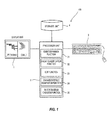
- Fig. 1 illustrates the general arrangement of an FT diagram creation assistance device 100 according to an embodiment of the present invention.
- the FT diagram creation assistance device 100 is provided with a display unit 1, a processor unit 2, and an operation unit 3.
- the processor unit 2 is formed by a microprocessor, RAM, ROM and the like.
- the microprocessor reads a program stored in the ROM or in a storage unit 4 that will be described later into the RAM and executes the program, so as to implement an event expansion function 21, an event classification function 22, an edit function 23, an expansion result examination function 24, and a block diagram creation function 25.
- An FT diagram is represented by XML data describing the relationship between events (tree structure), contents and physical quantities of the respective events, and the like, in the processor unit 2, and the XML data corresponding to the FT diagram, together with the FT diagram, is displayed on the display unit 1.
- the event expansion function 21 is the function of automatically expanding a specific event (a fault of a system, a subsystem, or a control system) to lower events, based on input/output relationship in a block diagram of the part relating to the specific event. The details of processing for implementing this function will be described later.
- the event classification function 22 is the function of classifying the specific event into a fault of hardware or the fault of the system (including the subsystem) or a control system. An operator inputs via the operation unit 3 whether the event falls under the fault of the hardware or the fault of the system or the control system, and then the classification is made based on the input result.
- the edit function 23 is the function of editing the FT diagram on the display unit 1 based on the input from the operation unit 3. Specific functions include addition of the event, movement of the event, copy and paste of the event, deletion of the event, addition and correction of the contents of the event, addition and correction of the physical quantities of the respective events, and the like.
- the contents edited on the display unit 1 are immediately reflected on the XML data representing the FT diagram.
- the block diagram creation function 25 is the function of creating the block diagram on the display unit 1, based on the input from the operation unit 3. Specific functions include addition of the block, movement of the block, copy and paste of the block, deletion of the block, addition and correction of the contents of the block, addition and correction of the input/output relationship of the block, and the like.
- the operation unit 3 is an input device such as a keyboard, a mouse, or the like.
- the operation unit 3 receives various types of operation from the operator.
- Fig. 2 is a flowchart illustrating a creating procedure of the FT diagram.
- the creating procedure of the FT diagram will be explained specifically with reference to this flowchart.
- An explanation will be given to the case of analyzing the fault event of "large shift shock" of an automatic transmission (hereinafter referred to as an "AT") as a specific example according to this embodiment, in order to facilitate understanding of the contents of the procedure.
- AT automatic transmission
- the fault event is identified.
- the operator operates the operation unit 3 and creates a new fault event on the display unit 1 by using the edit function 23 of the processor unit 2, so as to identify the fault event.
- the event of the "large shift shock" that is created by the operator on the display unit 1 is identified as the fault event.
- a block diagram of a system corresponding to the fault event is created.
- the block diagram is created on the display unit 1 by the operator operating the operation unit 3 by using the block diagram creation function 25 of the processor unit 2.
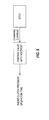
- Fig. 4 is a block diagram created in the specific example. According to the created block diagram, parts relating to the shift shock are a "vehicle”, an "AT”, and an “engine”, and output torque of the engine is inputted to the AT, output torque of the AT is inputted to the vehicle, and as a result of this, the shift shock is outputted from the vehicle.
- the fault event is expanded into the lower events.
- the expansion into the lower events is carried out automatically by using the event expansion function 21 of the processor unit 2, based on the input/output relationship in the block diagram created in S2, according to the procedure illustrated in Fig. 3 .
- the processor unit 2 starts from the downstream end of the block diagram and determines whether the block exists or not on the upstream side. The processing proceeds to S22 if there is the block on the upstream side, and if there is not, the processing finishes.
- the processor unit 2 sets the block on the upstream side as a block to be analyzed.
- the block of the "vehicle” exists on the upstream side, and hence this block is set as the block to be analyzed.
- the processor unit 2 adds "abnormality of block to be analyzed" as the lower event.
- "vehicle abnormality” is added as the lower event of the "large shift shock” (51 in Fig. 5 ).
- the processor unit 2 determines whether an input is made into the block to be analyzed or not. The processing proceeds to S25 if the input is made into the block to be analyzed, and if it is not, the processing finishes.
- the processor unit 2 adds "input abnormality into block to be analyzed" on the same level as the event added in S23.
- the processor unit 2 determines whether the input into the block to be analyzed is the same as the output from another block or not. The processing proceeds to S27 if the input into the block to be analyzed is the same as the output from another block, and if it is not, the processing finishes.
- the processor unit 2 adds "output abnormality of another block" to the lower level of the event added in S25.
- the fault event is expanded into the lower events and, in the specific example illustrated in Fig. 4 , the "large shift shock" as the fault event is automatically expanded based on the input/output relationship of the respective blocks, into the state as illustrated in Fig. 5 .
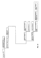
- Fig. 6 illustrates the expansion result after the correction. Corrected parts are in broken line boxes, and the "vehicle abnormality" and “AT abnormality” in Fig. 5 are corrected as "low damping rate (high transmission rate) of vehicle” and “large torque transmission capacity of AT", respectively.
- the event that can be expanded into the further lower event (the lower event that is not the fundamental event, which will be referred to as an "expandable event” below) is identified.
- the operator operates the operation unit 3, and selects the event that is determined to be expandable based on knowledge of the past and expansion examples of similar events, from among the lower events, so as to make the identification.
- the identification of the expandable event is made by the operator operating the operation unit 3 in this case, but the expandable event may be identified automatically based on the result of comparison with a list of expandable events stored in the storage unit 4.
- the "large torque transmission capacity of AT" is identified as the expandable event.
- the processor unit 2 determines whether the expandable event is the fault of the hardware, or the fault of the subsystem or the control system. For example, a selection screen is displayed on the display unit 1, and the operator selects either the fault of the hardware, or the fault of the subsystem or the control system via the operation unit 3, so as to make this determination based on the selection result.
- This kind of determination is made because an expansion procedure of the expandable event is different between the case where the expandable event is the fault of the hardware and the case where the expandable event is the fault of the subsystem or the control system.
- the processing proceeds to S8, and when it is determined that the expandable event is the fault of the subsystem or the control system, the processing proceeds to S10.
- the expandable event may be classified automatically by the processor unit 2 referring to a table stored in the storage unit 4, the table indicating that the various events are either the faults of the hardware or the faults of the subsystem or the control system.
- the "large torque transmission capacity of AT" is the fault of the hardware, and therefore, the processing proceeds to S8.
- the expandable event is expanded into the further lower events, according to the expansion method suitable for the fault of the hardware.
- the operator operates the operation unit 3 to expand the expandable event on the display unit 1.
- the operator operates the operation unit 3 and adds the lower events (the contents of the events and the physical quantities thereof) of the expandable event by using the edit function 23 of the processor unit 2, so as to make the expansion.
- Fig. 7 illustrates the state in which the "large torque transmission capacity of AT" in Fig. 6 is expanded into the further lower events.
- An expanded part is in a broken line box.
- the processor unit 2 determines whether the expansion of the expandable event in S8 is made properly or not. This determination is made by using the expansion result examination function 24 of the processor unit 2, based on the relationship between the physical quantity of the expandable event and the physical quantities of its lower events. Specifically, the processor unit 2 determines whether either one of the following is satisfied or not, and determines that the expansion of the expandable event is made properly when either one of these is satisfied (physical quantity dimensional indexing method).
- Fig. 8 illustrates the physical quantities of the respective events in the part expanded in S8.
- the physical quantity of the "large torque transmission capacity of AT", as the expandable event is Nm/s
- the physical quantities of "large clutch capacity”, “short clutch operation time”, and “short clutch pressure operation time”, as its lower events are Nm, s, and s, respectively.
- the processing returns back to S5 to identify another expandable event and carry out the processing in and after S6 again. If this is not the case, the processing returns back to S8 to correct the event expanded from the expandable event.
- the processor unit 2 expands the expandable event into the further lower events, according to the expansion method suitable for the fault of the subsystem or the control system.
- a block diagram of the subsystem or the control system is created.
- the operator operates the operation unit 3 by using the block diagram creation function 25 of the processor unit 2, so as to create the block diagram on the display unit 1.
- the "short clutch pressure operation time" in Fig. 8 is the expandable event and is the fault of the subsystem, and therefore, the processing proceeds to S10, and a block diagram of the subsystem is created.
- Fig. 9 is the created block diagram.
- the subsystem is formed by a "control valve with solenoid” and an "ATCU", and a command current is inputted from the "ATCU” into the "control valve with solenoid”.
- the processor unit 2 expands the expandable event into the further lower event.
- the expanding procedure of the expandable event is the same as the procedure illustrated in Fig. 3 , which is performed automatically by using the event expansion function 21 of the processor unit 2, based on the input/output relationship in the block diagram created in S10.
- Fig. 10 illustrates the state in which the "short clutch pressure operation time" as the expandable event is expanded, and "large SOL command current" is added to its lower level.
- the expansion result of S11 is corrected. Specifically, the operator operates the operation unit 3, selects the lower event whose contents need to be corrected, from among the lower events, and rewrites the contents by using the edit function 23 of the processor unit 2, so as to make the correction.
- the "large SOL command current" is the expandable event and is the fault of the control system, and therefore, a corresponding block diagram is created again in S10 ( Fig. 11 ), and the "large SOL command current” is expanded into the further lower events based on the input/output relationship of this block diagram ( Fig. 12 ), and the expansion result is corrected (a part in a broken line box in Fig. 13 ). It should be noted that only the events lower than the "short clutch pressure operation time" are illustrated in Fig. 12 and Fig. 13 .
- the FT diagram of the fault event is created by the above-described procedure.
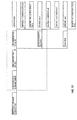
- Fig. 14 is an FT diagram of the fault event of the "large shift shock", which is created by the above-described procedure.
- parts in boxes A, B, and C are the faults of the system, the subsystem, or the control system, and are created by the procedure (S2 to S4, S10 to S 12) in which the events are automatically expanded into the lower events from the input/output relationship in the block diagram created by the operator, and the operator corrects the events as appropriate.
- a part in a box D is the fault of the hardware, and is created by the procedure (S8, S9) in which examines whether the expansion made by the operator is proper or not by using the relationship between the physical quantity of the expandable event and the physical quantities of its lower events.
- the expansion procedure to the lower events changes according to the type of the event, which makes it possible to create the FT diagram with the less workload and with the higher accuracy.
Landscapes
- Engineering & Computer Science (AREA)
- Physics & Mathematics (AREA)
- General Physics & Mathematics (AREA)
- Theoretical Computer Science (AREA)
- Automation & Control Theory (AREA)
- Quality & Reliability (AREA)
- General Engineering & Computer Science (AREA)
- Health & Medical Sciences (AREA)
- Biomedical Technology (AREA)
- Debugging And Monitoring (AREA)
- Testing And Monitoring For Control Systems (AREA)
- Information Retrieval, Db Structures And Fs Structures Therefor (AREA)
Abstract
Description
- The present invention relates to technology for analyzing a cause of a failure of a device, a system and the like, and improving reliability thereof.
- A fault tree analysis (FTA) is a technique for expanding a fault event into causative lower events by taking a logical sum (OR) or a logical product (AND) thereof, so as to create a tree structure (hereinafter referred to as an "FT diagram"), and for extracting a major cause from the lower events to reexamine its design in order to prevent the occurrence of a fault. In creating the FT diagram, comprehensive knowledge and a high degree of specialization in its field are required, and therefore, technology for assisting the creation of the FT diagram is required (
JP2009-289020A -
Fig. 15 is an example of the FT diagram. In this example, the fault event of "high power transmission loss by pulley" is analyzed. As this fault event is caused at the time of "large slip amount" or "large frictional force", the "large slip amount" and the "large frictional force" are the lower events of the fault event, which have the logical sum relationship. - As the event of the "large frictional force" is caused at the time of "large reaction force" or "large coefficient of friction", the "large frictional force" and the "large coefficient of friction" are the lower events of the "large frictional force", which have the logical sum relationship. As the event of the "large reaction force" is caused at the time of "large belt tension", the "large belt tension" is the lower event of the "large reaction force".
- The events of the "large slip amount", the "large belt tension", and the "large coefficient of friction" that cannot be expanded into further lower events, among the above-described events, are referred to as fundamental events, and it is necessary to examine measures against these fundamental events in order to prevent the occurrence of the fault event.
- It should be noted that, in this example, higher events and the lower events are connected simply by lines, and no description is made whether the lower events on the same level have the logical sum relationship or the logical product relationship. The reason for this is that, as most of the lower events on the same level have the logical sum relationship, the higher events and the lower events, and the lower events on the same level are connected simply by the lines when the events have the logical sum relationship, and the description of "AND", meaning the logical product, is made next to the line connecting the higher event and the lower event when the events have the logical product relationship.
- It is an object of the present invention to create an FT diagram with a less workload and with higher accuracy.
- According to an aspect, creation of the FT diagram is assisted by: classifying an event as a fault of hardware or a fault of a system (including a subsystem) or a control system; expanding the event into lower events, acquiring physical quantities of the event and the lower events, and examining whether the event is expanded properly or not based on relationship between the physical quantity of the event and the physical quantities of the lower events, when the event is classified as the fault of the hardware; and creating a block diagram of the system or the control system, and expanding the event into the lower events based on input/output relationship in the block diagram of the system or the control system, when the event is classified as the fault of the system or the control system.
- According to another aspect, creation of the FT diagram is assisted by: creating a block diagram of a system relating to a fault event, and expanding the fault event into lower events based on input/output relationship in the block diagram; allowing the event capable of expanding into a further lower event, among the lower events, to be an expandable event, and classifying the expandable event as a fault of hardware or a fault of a subsystem or a control system; expanding the expandable event into the further lower event, acquiring physical quantities of the expandable event and the further lower event, and examining whether the expandable event is expanded properly or not based on relationship between the physical quantity of the expandable event and the physical quantity of the further lower event, when the expandable event is classified as the fault of the hardware; and creating a block diagram of the subsystem or the control system, and expanding the expandable event into the further lower event based on input/output relationship in the block diagram of the subsystem or the control system, when the expandable event is classified as the fault of the subsystem or the control system.
- According to these aspects, it is possible to create the FT diagram with the less workload and with the higher accuracy.
- An embodiment of the present invention and advantages of the present invention will be explained in detail below, with reference to the attached drawings.
-
-
Fig. 1 is a view illustrating the general arrangement of an FT diagram creation assistance device; -
Fig. 2 is a flowchart illustrating a creating procedure of an FT diagram; -
Fig. 3 is a flowchart illustrating a procedure of expanding a specific event into lower events based on input/output relationship in a block diagram; -
Fig. 4 is a block diagram of a system relating to "large shift shock"; -
Fig. 5 is a view explaining the creating procedure of the FT diagram; -
Fig. 6 is a view explaining the creating procedure of the FT diagram; -
Fig. 7 is a view explaining the creating procedure of the FT diagram; -
Fig. 8 is a view explaining the creating procedure of the FT diagram; -
Fig. 9 is a view explaining the creating procedure of the FT diagram; -
Fig. 10 is a view explaining the creating procedure of the FT diagram; -
Fig. 11 is a view explaining the creating procedure of the FT diagram; -
Fig. 12 is a view explaining the creating procedure of the FT diagram; -
Fig. 13 is a view explaining the creating procedure of the FT diagram; -
Fig. 14 is a completed FT diagram; and -
Fig. 15 is an example of the FT diagram. -
Fig. 1 illustrates the general arrangement of an FT diagramcreation assistance device 100 according to an embodiment of the present invention. The FT diagramcreation assistance device 100 is provided with adisplay unit 1, aprocessor unit 2, and anoperation unit 3. - The
processor unit 2 is formed by a microprocessor, RAM, ROM and the like. The microprocessor reads a program stored in the ROM or in astorage unit 4 that will be described later into the RAM and executes the program, so as to implement anevent expansion function 21, anevent classification function 22, anedit function 23, an expansionresult examination function 24, and a blockdiagram creation function 25. - An FT diagram is represented by XML data describing the relationship between events (tree structure), contents and physical quantities of the respective events, and the like, in the
processor unit 2, and the XML data corresponding to the FT diagram, together with the FT diagram, is displayed on thedisplay unit 1. - The
event expansion function 21 is the function of automatically expanding a specific event (a fault of a system, a subsystem, or a control system) to lower events, based on input/output relationship in a block diagram of the part relating to the specific event. The details of processing for implementing this function will be described later. - The
event classification function 22 is the function of classifying the specific event into a fault of hardware or the fault of the system (including the subsystem) or a control system. An operator inputs via theoperation unit 3 whether the event falls under the fault of the hardware or the fault of the system or the control system, and then the classification is made based on the input result. - The
edit function 23 is the function of editing the FT diagram on thedisplay unit 1 based on the input from theoperation unit 3. Specific functions include addition of the event, movement of the event, copy and paste of the event, deletion of the event, addition and correction of the contents of the event, addition and correction of the physical quantities of the respective events, and the like. The contents edited on thedisplay unit 1 are immediately reflected on the XML data representing the FT diagram. - The block
diagram creation function 25 is the function of creating the block diagram on thedisplay unit 1, based on the input from theoperation unit 3. Specific functions include addition of the block, movement of the block, copy and paste of the block, deletion of the block, addition and correction of the contents of the block, addition and correction of the input/output relationship of the block, and the like. - The
operation unit 3 is an input device such as a keyboard, a mouse, or the like. Theoperation unit 3 receives various types of operation from the operator. -
Fig. 2 is a flowchart illustrating a creating procedure of the FT diagram. The creating procedure of the FT diagram will be explained specifically with reference to this flowchart. An explanation will be given to the case of analyzing the fault event of "large shift shock" of an automatic transmission (hereinafter referred to as an "AT") as a specific example according to this embodiment, in order to facilitate understanding of the contents of the procedure. - In S1, the fault event is identified. The operator operates the
operation unit 3 and creates a new fault event on thedisplay unit 1 by using theedit function 23 of theprocessor unit 2, so as to identify the fault event. In the specific example, the event of the "large shift shock" that is created by the operator on thedisplay unit 1 is identified as the fault event. - In S2, a block diagram of a system corresponding to the fault event is created. The block diagram is created on the
display unit 1 by the operator operating theoperation unit 3 by using the blockdiagram creation function 25 of theprocessor unit 2. -
Fig. 4 is a block diagram created in the specific example. According to the created block diagram, parts relating to the shift shock are a "vehicle", an "AT", and an "engine", and output torque of the engine is inputted to the AT, output torque of the AT is inputted to the vehicle, and as a result of this, the shift shock is outputted from the vehicle. - Returning back to
Fig. 2 and in S3, the fault event is expanded into the lower events. The expansion into the lower events is carried out automatically by using theevent expansion function 21 of theprocessor unit 2, based on the input/output relationship in the block diagram created in S2, according to the procedure illustrated inFig. 3 . - The procedure of expanding the fault event into the lower events will be explained with reference to
Fig. 3 . - First, in S21, the
processor unit 2 starts from the downstream end of the block diagram and determines whether the block exists or not on the upstream side. The processing proceeds to S22 if there is the block on the upstream side, and if there is not, the processing finishes. - In S22, the
processor unit 2 sets the block on the upstream side as a block to be analyzed. In the specific example illustrated inFig. 4 , the block of the "vehicle" exists on the upstream side, and hence this block is set as the block to be analyzed. - In S23, the
processor unit 2 adds "abnormality of block to be analyzed" as the lower event. In the specific example, "vehicle abnormality" is added as the lower event of the "large shift shock" (51 inFig. 5 ). - In S24, the
processor unit 2 determines whether an input is made into the block to be analyzed or not. The processing proceeds to S25 if the input is made into the block to be analyzed, and if it is not, the processing finishes. - In S25, the
processor unit 2 adds "input abnormality into block to be analyzed" on the same level as the event added in S23. - In the specific example illustrated in
Fig. 4 , the torque is inputted from the "AT" into the "vehicle", and hence "large input torque to vehicle" is added as the lower event of the "large shift shock" on the same level as the "vehicle abnormality" added in S23 (52 inFig. 5 ). - In S26, the
processor unit 2 determines whether the input into the block to be analyzed is the same as the output from another block or not. The processing proceeds to S27 if the input into the block to be analyzed is the same as the output from another block, and if it is not, the processing finishes. - In the specific example as illustrated in
Fig. 4 , the input into the "vehicle", as the block to be analyzed, is the same as the output from the "AT", and therefore, the processing proceeds to S27. - In S27, the
processor unit 2 adds "output abnormality of another block" to the lower level of the event added in S25. - In the specific example illustrated in
Fig. 4 , "large output torque of AT" is added to the lower level of the "large input torque to vehicle" added in S25 (53 inFig. 5 ). - Thereafter, the processing returns to S21, and the determination is made whether the block exists on the further upstream side of the block to be analyzed or not (S21), and the processing in and after S22 is repeated when the block exists on the further upstream side.
- According to the processing as described thus far, the fault event is expanded into the lower events and, in the specific example illustrated in
Fig. 4 , the "large shift shock" as the fault event is automatically expanded based on the input/output relationship of the respective blocks, into the state as illustrated inFig. 5 . - Returning back to
Fig. 2 , the explanation about the creating procedure of the FT diagram will be continued. - In S4, the contents of the expansion result of S3 are corrected. In this case, the operator operates the
operation unit 3, selects the lower event that needs to be corrected, and corrects the contents as appropriate by using theedit function 23, when the expansion result of S3 is not perfect. -
Fig. 6 illustrates the expansion result after the correction. Corrected parts are in broken line boxes, and the "vehicle abnormality" and "AT abnormality" inFig. 5 are corrected as "low damping rate (high transmission rate) of vehicle" and "large torque transmission capacity of AT", respectively. - In S5, the event that can be expanded into the further lower event (the lower event that is not the fundamental event, which will be referred to as an "expandable event" below) is identified. The operator operates the
operation unit 3, and selects the event that is determined to be expandable based on knowledge of the past and expansion examples of similar events, from among the lower events, so as to make the identification. - The identification of the expandable event is made by the operator operating the
operation unit 3 in this case, but the expandable event may be identified automatically based on the result of comparison with a list of expandable events stored in thestorage unit 4. - In the specific example illustrated in
Fig. 6 , the "large torque transmission capacity of AT" is identified as the expandable event. - Next, it is determined whether the expandable event exists or not in S6. This determination is made based on whether the specific event is identified as the expandable event in S5 or not. When there is no expandable event, the FT diagram has been completed by the expansion in S3, the correction of the expansion result in S4, or the processing in and after S7 that will be explained later, and therefore, the processing finishes. If this is not the case, the processing proceeds to S7.
- In S7, the
processor unit 2 determines whether the expandable event is the fault of the hardware, or the fault of the subsystem or the control system. For example, a selection screen is displayed on thedisplay unit 1, and the operator selects either the fault of the hardware, or the fault of the subsystem or the control system via theoperation unit 3, so as to make this determination based on the selection result. - This kind of determination is made because an expansion procedure of the expandable event is different between the case where the expandable event is the fault of the hardware and the case where the expandable event is the fault of the subsystem or the control system. When it is determined that the expandable event is the fault of the hardware, the processing proceeds to S8, and when it is determined that the expandable event is the fault of the subsystem or the control system, the processing proceeds to S10.
- Although the classification of the expandable event is made based on the input from the
operation unit 3 in this case, the expandable event may be classified automatically by theprocessor unit 2 referring to a table stored in thestorage unit 4, the table indicating that the various events are either the faults of the hardware or the faults of the subsystem or the control system. - In the specific example illustrated in
Fig. 6 , the "large torque transmission capacity of AT" is the fault of the hardware, and therefore, the processing proceeds to S8. - In S8 and S9, the expandable event is expanded into the further lower events, according to the expansion method suitable for the fault of the hardware.
- First, in S8, the operator operates the
operation unit 3 to expand the expandable event on thedisplay unit 1. The operator operates theoperation unit 3 and adds the lower events (the contents of the events and the physical quantities thereof) of the expandable event by using theedit function 23 of theprocessor unit 2, so as to make the expansion. -
Fig. 7 illustrates the state in which the "large torque transmission capacity of AT" inFig. 6 is expanded into the further lower events. An expanded part is in a broken line box. - In S9, the
processor unit 2 determines whether the expansion of the expandable event in S8 is made properly or not. This determination is made by using the expansionresult examination function 24 of theprocessor unit 2, based on the relationship between the physical quantity of the expandable event and the physical quantities of its lower events. Specifically, theprocessor unit 2 determines whether either one of the following is satisfied or not, and determines that the expansion of the expandable event is made properly when either one of these is satisfied (physical quantity dimensional indexing method). - A unit of the physical quantity of the expandable event can be represented by addition and subtraction of units of the physical quantities of its lower events. In other words, the physical quantity of the expandable event is commensurate with the physical quantities of its lower events.
- The unit of the physical quantity of the expandable event can be represented by multiplication and division or exponentiation of the units of the physical quantities of its lower events. In other words, the unit of the physical quantity of the expandable event can be represented by using the units of the physical quantities of its lower events.
-
Fig. 8 illustrates the physical quantities of the respective events in the part expanded in S8. The physical quantity of the "large torque transmission capacity of AT", as the expandable event, is Nm/s, and the physical quantities of "large clutch capacity", "short clutch operation time", and "short clutch pressure operation time", as its lower events, are Nm, s, and s, respectively. In this example, the physical quantity of the expandable event can be represented by the division of the physical quantities of its lower events (Nm /s = Nm ÷ s), and therefore, it is determined that the expansion is made properly in this case. - When the expansion of the expandable event is made properly, the processing returns back to S5 to identify another expandable event and carry out the processing in and after S6 again. If this is not the case, the processing returns back to S8 to correct the event expanded from the expandable event.
- In the specific example of
Fig. 8 , the "short clutch pressure operation time" that is added as a result of the expansion is identified as the expandable event, and the processing in and after S6 is carried out again. - In S10 to S12, the
processor unit 2 expands the expandable event into the further lower events, according to the expansion method suitable for the fault of the subsystem or the control system. - In S10, a block diagram of the subsystem or the control system is created. The operator operates the
operation unit 3 by using the blockdiagram creation function 25 of theprocessor unit 2, so as to create the block diagram on thedisplay unit 1. - In the specific example, the "short clutch pressure operation time" in
Fig. 8 is the expandable event and is the fault of the subsystem, and therefore, the processing proceeds to S10, and a block diagram of the subsystem is created. -
Fig. 9 is the created block diagram. The subsystem is formed by a "control valve with solenoid" and an "ATCU", and a command current is inputted from the "ATCU" into the "control valve with solenoid". - In S11, the
processor unit 2 expands the expandable event into the further lower event. The expanding procedure of the expandable event is the same as the procedure illustrated inFig. 3 , which is performed automatically by using theevent expansion function 21 of theprocessor unit 2, based on the input/output relationship in the block diagram created in S10. -
Fig. 10 illustrates the state in which the "short clutch pressure operation time" as the expandable event is expanded, and "large SOL command current" is added to its lower level. - In S12, the expansion result of S11 is corrected. Specifically, the operator operates the
operation unit 3, selects the lower event whose contents need to be corrected, from among the lower events, and rewrites the contents by using theedit function 23 of theprocessor unit 2, so as to make the correction. - In the specific example illustrated in
Fig. 10 , the expansion of the "short clutch pressure operation time" is made properly, and therefore, no correction is made in S12 in particular. - Thereafter, the processing returns back to S5 to identify another expandable event and carry out the processing in and after S6 again.
- In the example illustrated in
Fig. 10 , the "large SOL command current" is the expandable event and is the fault of the control system, and therefore, a corresponding block diagram is created again in S10 (Fig. 11 ), and the "large SOL command current" is expanded into the further lower events based on the input/output relationship of this block diagram (Fig. 12 ), and the expansion result is corrected (a part in a broken line box inFig. 13 ). It should be noted that only the events lower than the "short clutch pressure operation time" are illustrated inFig. 12 andFig. 13 . - According to this embodiment, the FT diagram of the fault event is created by the above-described procedure.
-
Fig. 14 is an FT diagram of the fault event of the "large shift shock", which is created by the above-described procedure. In the diagram, parts in boxes A, B, and C are the faults of the system, the subsystem, or the control system, and are created by the procedure (S2 to S4, S10 to S 12) in which the events are automatically expanded into the lower events from the input/output relationship in the block diagram created by the operator, and the operator corrects the events as appropriate. - In the diagram, a part in a box D is the fault of the hardware, and is created by the procedure (S8, S9) in which examines whether the expansion made by the operator is proper or not by using the relationship between the physical quantity of the expandable event and the physical quantities of its lower events.
- Thus, according to this embodiment, the expansion procedure to the lower events changes according to the type of the event, which makes it possible to create the FT diagram with the less workload and with the higher accuracy.
- Although the embodiment of the present invention has been explained thus far, the above-described embodiment is only one of the examples of applying the present invention, and is not intended to limit the technical scope of the present invention to the specific structure of the above-described embodiment.
- The present application claims priority to Japanese Patent Application No.
2011-229597
Claims (4)
- An FT diagram creation assistance device, comprising:an event classification unit that classifies an event as a fault of hardware or a fault of a system or a control system;an expansion result examination unit that, when the event is classified as the fault of the hardware, expands the event into lower events based on an input from an operator, acquires physical quantities of the event and the lower events, and examines whether the event is expanded properly or not based on relationship between the physical quantity of the event and the physical quantities of the lower events; andan event expansion unit that, when the event is classified as the fault of the system or the control system, creates a block diagram of the system or the control system based on the input from the operator, and expands the event into the lower events based on input/output relationship in the block diagram of the system or the control system.
- An FT diagram creation assistance device, comprising:a first event expansion unit that creates a block diagram of a system relating to a fault event based on an input from an operator, and expands the fault event into lower events based on input/output relationship in the block diagram;an event classification unit that allows the event capable of expanding into a further lower event, among the lower events, to be an expandable event, and classifies the expandable event as a fault of hardware or a fault of a subsystem or a control system;an expansion result examination unit that, when the expandable event is classified as the fault of the hardware, expands the expandable event into the further lower event based on the input from the operator, acquires physical quantities of the expandable event and the further lower event, and examines whether the expandable event is expanded properly or not based on relationship between the physical quantity of the expandable event and the physical quantity of the further lower event; anda second event expansion unit that, when the expandable event is classified as the fault of the subsystem or the control system, creates a block diagram of the subsystem or the control system based on the input from the operator, and expands the expandable event into the further lower event based on input/output relationship in the block diagram of the subsystem or the control system.
- An FT diagram creation assistance method, comprising:classifying an event as a fault of hardware or a fault of a system or a control system;expanding the event into lower events, acquiring physical quantities of the event and the lower events, and examining whether the event is expanded properly or not based on relationship between the physical quantity of the event and the physical quantities of the lower events, when the event is classified as the fault of the hardware; andcreating a block diagram of the system or the control system, and expanding the event into the lower events based on input/output relationship in the block diagram of the system or the control system, when the event is classified as the fault of the system or the control system.
- An FT diagram creation assistance method, comprising:creating a block diagram of a system relating to a fault event, and expanding the fault event into lower events based on input/output relationship in the block diagram;allowing the event capable of expanding into a further lower event, among the lower events, to be an expandable event, and classifying the expandable event as a fault of hardware or a fault of a subsystem or a control system;expanding the expandable event into the further lower event, acquiring physical quantities of the expandable event and the further lower event, and examining whether the expandable event is expanded properly or not based on relationship between the physical quantity of the expandable event and the physical quantity of the further lower event, when the expandable event is classified as the fault of the hardware; andcreating a block diagram of the subsystem or the control system, and expanding the expandable event into the further lower event based on input/output relationship in the block diagram of the subsystem or the control system, when the expandable event is classified as the fault of the subsystem or the control system.
Applications Claiming Priority (2)
| Application Number | Priority Date | Filing Date | Title |
|---|---|---|---|
| JP2011229597 | 2011-10-19 | ||
| PCT/JP2012/072917 WO2013058028A1 (en) | 2011-10-19 | 2012-09-07 | Ft diagram creation assistance device and ft diagram creation assistance method |
Publications (2)
| Publication Number | Publication Date |
|---|---|
| EP2770388A1 true EP2770388A1 (en) | 2014-08-27 |
| EP2770388A4 EP2770388A4 (en) | 2015-11-25 |
Family
ID=48140684
Family Applications (1)
| Application Number | Title | Priority Date | Filing Date |
|---|---|---|---|
| EP12841866.2A Withdrawn EP2770388A4 (en) | 2011-10-19 | 2012-09-07 | FOURIER TRANSFORMATION DIAGRAM CREATION DEVICE (FT) AND METHOD FOR AIDING FT DIAGRAM CREATION |
Country Status (6)
| Country | Link |
|---|---|
| US (1) | US10337965B2 (en) |
| EP (1) | EP2770388A4 (en) |
| JP (1) | JP5789672B2 (en) |
| KR (1) | KR101599160B1 (en) |
| CN (1) | CN103797432B (en) |
| WO (1) | WO2013058028A1 (en) |
Cited By (1)
| Publication number | Priority date | Publication date | Assignee | Title |
|---|---|---|---|---|
| WO2022111840A1 (en) * | 2020-11-25 | 2022-06-02 | Hitachi Energy Switzerland Ag | Configurable fault tree structure for electrical equipment |
Family Cites Families (11)
| Publication number | Priority date | Publication date | Assignee | Title |
|---|---|---|---|---|
| JPH05143570A (en) * | 1991-11-19 | 1993-06-11 | Nippon Telegr & Teleph Corp <Ntt> | How to create a fault tree |
| JPH11184875A (en) * | 1997-12-22 | 1999-07-09 | Mitsubishi Heavy Ind Ltd | FT diagram creation method and apparatus |
| WO2001055806A1 (en) * | 2000-01-29 | 2001-08-02 | Abb Research Ltd. | Method for automatic fault tree synthesis |
| KR100419296B1 (en) * | 2003-07-18 | 2004-02-19 | (주)아이겐웍스 | A Method and Program for Analyzing Failure Modes |
| JP3808893B1 (en) * | 2005-07-14 | 2006-08-16 | 国立大学法人 岡山大学 | Fault diagnosis device, program and recording medium |
| JP2009123110A (en) * | 2007-11-16 | 2009-06-04 | Panasonic Electric Works Co Ltd | Software development support system |
| KR20090098206A (en) * | 2008-03-13 | 2009-09-17 | 신한관세사법인 | FT service system and method |
| JP5146750B2 (en) | 2008-05-29 | 2013-02-20 | オムロン株式会社 | FT diagram creation program, FT diagram creation device, recording medium, and FT diagram creation method |
| JP5376133B2 (en) * | 2009-03-30 | 2013-12-25 | 日本電気株式会社 | Fault tree analysis generation method, fault tree analysis generation system, and program |
| CN101634966B (en) * | 2009-09-01 | 2010-09-29 | 南京大学 | A method for automated failure mode and effects analysis of software processes |
| CN101814114B (en) * | 2010-01-07 | 2012-03-21 | 北京航空航天大学 | Method for performing fault diagnosis by using model conversion |
-
2012
- 2012-09-07 KR KR1020147006589A patent/KR101599160B1/en not_active Expired - Fee Related
- 2012-09-07 JP JP2013539571A patent/JP5789672B2/en active Active
- 2012-09-07 WO PCT/JP2012/072917 patent/WO2013058028A1/en not_active Ceased
- 2012-09-07 EP EP12841866.2A patent/EP2770388A4/en not_active Withdrawn
- 2012-09-07 US US14/352,186 patent/US10337965B2/en active Active
- 2012-09-07 CN CN201280044124.9A patent/CN103797432B/en active Active
Cited By (3)
| Publication number | Priority date | Publication date | Assignee | Title |
|---|---|---|---|---|
| WO2022111840A1 (en) * | 2020-11-25 | 2022-06-02 | Hitachi Energy Switzerland Ag | Configurable fault tree structure for electrical equipment |
| CN116547617A (en) * | 2020-11-25 | 2023-08-04 | 日立能源瑞士股份公司 | Configurable fault tree structure for electrical equipment |
| US12578716B2 (en) | 2020-11-25 | 2026-03-17 | Hitachi Energy Ltd | Configurable fault tree structure for electrical equipment |
Also Published As
| Publication number | Publication date |
|---|---|
| CN103797432B (en) | 2016-09-07 |
| US10337965B2 (en) | 2019-07-02 |
| EP2770388A4 (en) | 2015-11-25 |
| KR20140049060A (en) | 2014-04-24 |
| US20150168269A1 (en) | 2015-06-18 |
| WO2013058028A1 (en) | 2013-04-25 |
| KR101599160B1 (en) | 2016-03-02 |
| JP5789672B2 (en) | 2015-10-07 |
| JPWO2013058028A1 (en) | 2015-04-02 |
| CN103797432A (en) | 2014-05-14 |
Similar Documents
| Publication | Publication Date | Title |
|---|---|---|
| US20060010429A1 (en) | Method, system and program for model based software development with test case generation and evaluation | |
| EP2597566B1 (en) | Software maintenance supporting device and electronic control device verified by the same | |
| US10061670B2 (en) | Method and apparatus for automatically generating a component fault tree of a safety-critical system | |
| US20130262934A1 (en) | Method and apparatus for automatically generating a test script for a graphical user interface | |
| JP2797698B2 (en) | Software reuse support method | |
| CN106547698A (en) | The processing method of coverage data, device and server | |
| CN112100077B (en) | Transaction testing method and device | |
| US20090037878A1 (en) | Web Application Development Tool | |
| US10337965B2 (en) | FT diagram creation assistance device and FT diagram creation assistance method | |
| JP2009110318A (en) | Fault information output control device and fault information output control method used therefor, and program thereof | |
| JPH10275093A (en) | Program test support device | |
| EP2746975A1 (en) | CAD drawing notes manager | |
| US12222845B2 (en) | Apparatus, method, and program for generating a test script for a web application based on screen transitions | |
| CN111026719B (en) | Data processing apparatus and control method thereof | |
| JP2009181180A (en) | Program generation tool inspection program, program generation tool inspection method, and program generation tool inspection apparatus | |
| Michelet et al. | Automation for digital forensics: Towards a classification model for the community | |
| US8756574B2 (en) | Using reverse time for coverage analysis | |
| JP2018147106A (en) | Program analyzer, program analysis method and program analysis program | |
| JP4583260B2 (en) | General-purpose computer operation procedure creation device, program, and storage medium | |
| US20260072425A1 (en) | Sign Detection System and Sign Detection Method | |
| CN115827480B (en) | Automatic test method, device and system for ship performance prediction APP | |
| JP2010128892A (en) | Database generation device, database generation method, and computer program | |
| US12585576B2 (en) | Test support apparatus and method for testing web applications | |
| US9524288B2 (en) | FT diagram generation aid device and FT diagram generation aid program | |
| US20230013943A1 (en) | Information processing device, setting method, and setting program |
Legal Events
| Date | Code | Title | Description |
|---|---|---|---|
| PUAI | Public reference made under article 153(3) epc to a published international application that has entered the european phase |
Free format text: ORIGINAL CODE: 0009012 |
|
| 17P | Request for examination filed |
Effective date: 20140429 |
|
| AK | Designated contracting states |
Kind code of ref document: A1 Designated state(s): AL AT BE BG CH CY CZ DE DK EE ES FI FR GB GR HR HU IE IS IT LI LT LU LV MC MK MT NL NO PL PT RO RS SE SI SK SM TR |
|
| DAX | Request for extension of the european patent (deleted) | ||
| RA4 | Supplementary search report drawn up and despatched (corrected) |
Effective date: 20151026 |
|
| RIC1 | Information provided on ipc code assigned before grant |
Ipc: G06Q 50/10 20120101ALI20151016BHEP Ipc: G05B 23/02 20060101AFI20151016BHEP Ipc: G06F 11/07 20060101ALI20151016BHEP |
|
| 17Q | First examination report despatched |
Effective date: 20170322 |
|
| STAA | Information on the status of an ep patent application or granted ep patent |
Free format text: STATUS: THE APPLICATION IS DEEMED TO BE WITHDRAWN |
|
| 18D | Application deemed to be withdrawn |
Effective date: 20200603 |