EP2770355A1 - Optical fiber cable with attached connector, and method of assembling optical fiber cable with attached connector - Google Patents
Optical fiber cable with attached connector, and method of assembling optical fiber cable with attached connector Download PDFInfo
- Publication number
- EP2770355A1 EP2770355A1 EP12853670.3A EP12853670A EP2770355A1 EP 2770355 A1 EP2770355 A1 EP 2770355A1 EP 12853670 A EP12853670 A EP 12853670A EP 2770355 A1 EP2770355 A1 EP 2770355A1
- Authority
- EP
- European Patent Office
- Prior art keywords
- optical fiber
- heat
- shrinkable tube
- fiber cable
- ferrule
- Prior art date
- Legal status (The legal status is an assumption and is not a legal conclusion. Google has not performed a legal analysis and makes no representation as to the accuracy of the status listed.)
- Granted
Links
Images




Classifications
-
- G—PHYSICS
- G02—OPTICS
- G02B—OPTICAL ELEMENTS, SYSTEMS OR APPARATUS
- G02B6/00—Light guides; Structural details of arrangements comprising light guides and other optical elements, e.g. couplings
- G02B6/24—Coupling light guides
- G02B6/36—Mechanical coupling means
- G02B6/38—Mechanical coupling means having fibre to fibre mating means
- G02B6/3807—Dismountable connectors, i.e. comprising plugs
- G02B6/3833—Details of mounting fibres in ferrules; Assembly methods; Manufacture
- G02B6/3855—Details of mounting fibres in ferrules; Assembly methods; Manufacture characterised by the method of anchoring or fixing the fibre within the ferrule
- G02B6/3861—Adhesive bonding
-
- G—PHYSICS
- G02—OPTICS
- G02B—OPTICAL ELEMENTS, SYSTEMS OR APPARATUS
- G02B6/00—Light guides; Structural details of arrangements comprising light guides and other optical elements, e.g. couplings
- G02B6/24—Coupling light guides
- G02B6/36—Mechanical coupling means
- G02B6/38—Mechanical coupling means having fibre to fibre mating means
- G02B6/3807—Dismountable connectors, i.e. comprising plugs
- G02B6/3887—Anchoring optical cables to connector housings, e.g. strain relief features
- G02B6/3889—Anchoring optical cables to connector housings, e.g. strain relief features using encapsulation for protection, e.g. adhesive, molding or casting resin
-
- G—PHYSICS
- G02—OPTICS
- G02B—OPTICAL ELEMENTS, SYSTEMS OR APPARATUS
- G02B6/00—Light guides; Structural details of arrangements comprising light guides and other optical elements, e.g. couplings
- G02B6/24—Coupling light guides
- G02B6/36—Mechanical coupling means
- G02B6/38—Mechanical coupling means having fibre to fibre mating means
- G02B6/3807—Dismountable connectors, i.e. comprising plugs
- G02B6/381—Dismountable connectors, i.e. comprising plugs of the ferrule type, e.g. fibre ends embedded in ferrules, connecting a pair of fibres
- G02B6/3818—Dismountable connectors, i.e. comprising plugs of the ferrule type, e.g. fibre ends embedded in ferrules, connecting a pair of fibres of a low-reflection-loss type
- G02B6/3821—Dismountable connectors, i.e. comprising plugs of the ferrule type, e.g. fibre ends embedded in ferrules, connecting a pair of fibres of a low-reflection-loss type with axial spring biasing or loading means
Definitions
- the present invention relates to an optical fiber cable having a connector in which an optical connector is assembled on the tip portion of the optical fiber cable, and an assembly method thereof (an assembly method of the optical fiber cable having a connector).
- an optical connector to a tight buffer type optical fiber cable (hereinafter, also referred to as an "optical fiber cable” or simply as a “cable") which is represented by an indoor optical fiber cable or a drop optical fiber cable
- a method which uses a so-called field assembly type optical connector or a method which assembles a factory assembly type optical connector including a ferrule through which an empty fiber hole penetrates is adopted.
- the field assembly type optical connector includes a short optical fiber (hereinafter, referred to as a "built-in optical fiber) which is inserted into and fixed to a ferrule in advance.
- the tip of the optical fiber in which a jacket of a cable terminal is removed and exposed is butted and connected to the rear end opposite to the front end which is positioned in the front end surface (splice end surface) of the ferrule of the built-in optical fiber, and thereby, the field assembly type optical connector is assembled on the tip of the cable (for example, refer to Japanese Unexamined Patent Application, First Publication No. 2010-145951 ).
- the assembly of the field assembly type optical connector on the tip portion of the cable has a structure in which the connecting points between the optical fibers further increases by one and the connecting points are accommodated in the inner portion of the connector, the entire length of the connector is lengthened, and thereby, there are disadvantages in which the structure of the connector is complicated, the costs increases, and the like.
- the field assembly type optical connector includes anchoring means for anchoring the jacket terminal of the cable, the configuration also becomes complicated and the costs increases.
- the factory assembly type optical connector since it is not necessary to accommodate the connecting points between the optical fibers and the configuration is simpler compared to the field assembly type optical connector, the costs are decreased.
- the factory assembly type optical connector is assembled on the tip portion of the cable, a portion which extends between the ferrule and the tip of the cable jacket is present in the optical fiber of the optical fiber cable, and there is a problem in that the mechanical strength of the portion is decreased.
- the present invention is made in consideration of the above-described circumstances, and an object thereof is to provide an optical fiber cable having a connector and an assembly method of the optical fiber cable having a connector capable of suppressing the entire length of a connector with a simple structure and of easily securing mechanical strength between a ferrule and the optical fiber cable at a low cost.
- the present invention provides the following configurations.
- a first aspect of the present invention includes, an optical fiber cable having an optical connector, including: an optical connector assembled on a tip portion of an optical fiber cable, including a ferrule in which an optical fiber protruding from a terminal of the optical fiber cable is inserted and fixed; and a reinforced portion formed by heating and shrinking a heat-shrinkable tube and by so solidifying a hot-melt adhesive of an inner portion of the heat-shrinkable tube after melting the hot-melt adhesive so as to integrate a rear end portion of the ferrule, the tip portion of the optical fiber cable which is disposed so as to be separated in a rear side of the ferrule, and the heat-shrinkable tube which accommodates the rear end portion of the ferrule and the tip portion of the optical fiber cable and in which the hot-melt adhesive is disposed in the inner portion of the heat-shrinkable tube.
- a second aspect of the present invention includes, in the first aspect, a protrusion portion formed in the rear end portion of the ferrule, increasing pull-out resistance of the heat-shrinkable tube.
- a third aspect of the present invention includes, in the first or the second aspect, tensile strength fibers disposed inside the heat-shrinkable tube or embedded to the heat-shrinkable tube, substantially equally disposed in a plurality of locations in a circumferential direction of the heat-shrinkable tube, extending along an axis line direction of the heat-shrinkable tube.
- a fourth aspect of the present invention includes, an assembly method of an optical fiber cable having a connector, including: a step of inserting and fixing an optical fiber protruding from a terminal of an optical fiber cable into a ferrule; a step of accommodating a rear end portion of an inserted and fixed ferrule and a tip portion of the optical fiber cable which is disposed so as to be separated in a rear side of the ferrule into a heat-shrinkable tube in which a hot-melt adhesive is disposed in an inner portion of the heat-shrinkable tube in advance, and a step of forming a reinforced portion, integrating a rear end portion of the ferrule, the tip portion of the optical fiber cable, and the heat-shrinkable tube by heating and shrinking an accommodating heat-shrinkable tube and by solidifying the hot-melt adhesive in the heat-shrinkable tube after melting the hot-melt adhesive.
- a fifth aspect of the present invention includes, in the fourth aspect, using a ferrule in which a protrusion portion which increases pull-out resistance of the heat-shrinkable tube, and the protrusion portion is formed in the rear end portion of the ferrule.
- a sixth aspect of the present invention includes, in the fifth aspect, the assembly method further include: the heat-shrinkable tube is used in which tensile strength fibers extending along an axis line direction of the heat-shrinkable tube are disposed inside the heat-shrinkable tube or embedded to the heat-shrinkable tube, the tensile strength fibers are substantially equally disposed in a plurality of locations in a circumferential direction of the heat-shrinkable tube; the rear end portion of the ferrule and the tip portion of the optical fiber cable are accommodated inside the heat-shrinkable tube so that the tensile strength fibers are disposed at a periphery of the rear end portion of the ferrule and the tip portion of the optical fiber cable; and the heat-shrinkable tube is heated and shrunk.
- a seventh aspect of the present invention includes, in any one of the fourth to sixth aspects, the assembly method further include: the heat-shrinkable tube is used in which the hot-melt adhesive is provided in a ring shape along an inner surface of a center portion in a longitudinal direction of the heat-shrinkable tube; the rear end portion of the ferrule and the tip portion of the optical fiber cable are accommodated inside the hot-melt adhesive; and the heat-shrinkable tube is heated and shrunk.
- the reinforced portion which is provided in the optical connector assembled on the terminal of the optical fiber cable has the configuration in which the rear end portion of the ferrule, the tip portion of the optical fiber cable, and the heat-shrinkable tube are integrated, mechanical strength between the rear end portion of the ferrule and the tip portion of the optical fiber cable can be easily secured.
- the structure of the reinforced portion is simple, and the reinforced portion can be simply assembled at a low cost.
- the optical connector since the optical connector has the structure in which the optical fiber protruding from the terminal of the optical fiber cable is directly inserted into the ferrule and fixed, it is not necessary to accommodate connecting points of the optical fiber.
- anchoring means for anchoring the optical fiber cable since anchoring means for anchoring the optical fiber cable is not required, the structure is simpler compared to a field assembly type optical connector having a configuration which accommodates connecting points in which optical fibers are butted and connected, and thereby, the entire length of the connector can be suppressed, and a decrease in the costs can be easily achieved.
- an optical connector 20 is assembled on the tip portion of an optical fiber cable 1.
- the optical fiber cable 1 is a tight buffer type optical fiber cable and is configured by collectively coating an optical fiber 2 and flexible linear tensile strength bodies 3 so as to be parallel to each other using a jacket 4 made of synthetic resin.
- the tensile strength bodies 3 there may be the strength body which is formed of tensile strength fibers such as an aramid fiber, a steel wire, or the like.
- the tensile strength bodies 3 are disposed so as to extend along the optical fiber 2 in both sides of the optical fiber 2.
- the optical fiber 2 is an optical fiber with a coating having a configuration in which the outer circumferential surface (side surface) of a bare optical fiber 2a is covered with a coating 2b.
- the optical fiber 2 there may be an optical fiber core, an optical fiber wire, or the like.
- the bare optical fiber 2a is a quartz-based optical fiber.
- the coating 2b is a resin coating in which ultraviolet-curable resin, polyamide resin, or the like is substantially concentrically coated in a single layer or a plurality of layers.
- optical fiber cable 1 there may be an indoor cable, a drop cable, or the like.
- a ferrule 30 to which the optical fiber 2 protruding from the terminal of the optical fiber cable 1 is inserted and fixed is accommodated in a sleeve-shaped housing 21, and thereby, the optical connector 20 is schematically configured.
- the optical connector 20 of the shown example is assembled using a housing 21, a knob 22 (coupling), and a boot 23 of a SC type optical connector (SC: Single-fiber Coupling optical fiber connector and an F04 type optical connector which is defined in JISC 5973).
- SC Single-fiber Coupling optical fiber connector and an F04 type optical connector which is defined in JISC 5973.
- the optical connector 20 includes a spring 26 which elastically biases the ferrule 30 to the front side of the connector (left side in FIG. 2 ) in the housing 21.
- the housing 21 is assembled by fitting (fitting into) the front end portion of a sleeve-shaped stop ring 25 to the rear end portion of a plug frame 24 which configures the front side portion of the housing.
- the plug frame 24 of the optical connector 20 of the shown example is formed in an angled tubular shape, and the stop ring 25 is formed in a cylindrical shape.
- the knob 22 is an angled tubular shape and is externally inserted to the housing 21, and the knob secures a slightly movable range in the axis line direction of the housing 21 and is slidably assembled.
- the ferrule 30 is a ferrule for a single-core optical connector (here, a SC type optical connector) and has a configuration in which a sleeve-shaped flange part 32 is fixed to a capillary shape ferrule main body 31.
- the ferrule main body 31 As a material for forming the ferrule main body 31, ceramic such as zirconia, or glass may be adopted. Moreover, in the ferrule main body 31, a fiber hole 31a which is a micropore is provided so as be penetrated, and the fiber hole coaxially extends to the center axis line of the ferrule main body 31 having a cylindrical shape.
- the flange part 32 is an integral molded part made of metal.
- the flange part is not limited to the part made of metal, and for example, the flange part may adopt a hard plastic part or the like.
- the flange part 32 includes a fixing ring portion 32a that is externally inserted to and fixed to the rear end portion opposite to a splice end surface 31b of the front end of the ferrule main body 31, and a sleeve portion 32b that extends from the fixing ring portion 32a to the rear side (the side opposite to the splice end surface 31b of the ferrule main body 31).
- the sleeve portion 32b is formed in a tubular shape that includes an inner hole 32c that is coaxial with the fixing ring portion 32a. Moreover, a flange portion 32d that protrudes over the entire outer circumference is circumferentially provided in the front end portion (the end portion opposite to the sleeve portion 32b) of the fixing ring portion 32a.
- the flange portion 32d functions as a flange portion of the ferrule 30.
- the optical fiber 2 is bonded and fixed to the ferrule 30 by adhesive that is filled in the fiber hole 31a and the inner hole 32c of the ferrule 30.
- the optical fiber 2 is inserted into and fixed to a fiber inner insertion hole 33 of the ferrule 30 that includes the fiber hole 31a and the inner hole 32c.
- the tip (front end) surface of the bare optical fiber 2a of the optical fiber 2 is aligned with the splice end surface 31b of the ferrule main body 31.
- the tip surface of the bare optical fiber 2a is ground at the surface that is continuous to the splice end surface 31b of the ferrule main body 31.
- the boot 23 of the optical connector 20 includes a sleeve-shaped mounting portion 23a that is assembled to the circumference of the stop ring 25 and a tapered tubular portion 23b having flexibility that extends from the front side sleeve portion 23a to the rear side (the side opposite to the plug frame 24) of the stop ring 25.
- the tapered tubular portion 23b is formed in a shape which is gradually tapered from the front side sleeve portion 23a to the rear side.
- the optical fiber cable 1 is drawn inside the tapered tubular portion 23b of the boot 23 and is drawn into the housing 21 of the optical connector 20.
- the tip portion of the optical fiber cable 1 is disposed so as to be separated from the ferrule 30 (specifically, the rear end of the sleeve portion 32b of the flange part 32) to the rear side.
- the optical connector 20 includes the sleeve portion 32b of the flange part 32 of the ferrule 30, the tip portion of the optical fiber cable 1, a heat-shrinkable tube 41 that accommodates the sleeve portion and the tip portion, and a reinforced portion 40 that is integrated by adhesive 42 filled in the inner portion of the heat-shrinkable tube 41 in the housing 21.
- one end portion in the axis line direction is externally inserted to and fixed to the sleeve portion 32b of the flange part 32 of the ferrule 30 (hereinafter, also referred to as a rear side sleeve portion 32b of the ferrule 30), and the other end portion in the axis line direction is provided so as to be externally inserted to and fixed to the tip portion of the optical fiber cable 1.
- the protrusion portion 32e that is exemplified in FIGS. 2 to 4B is formed in a flange shape which extends along the circumferential direction of the outer circumference of the sleeve portion 32b.
- the protrusion portions 32e are formed in a plurality of locations in the axis line direction of the sleeve portion 32b.
- the heat-shrinkable tube 41 that is externally inserted to and fixed to the rear side sleeve portion 32b of the ferrule 30 is formed in an unevenshape according to the unevenshape due to the presence of the protrusion portion 32e on the outer circumference of the sleeve portion 32b, and comes into press-contact with the outer circumference of the sleeve portion 32b.
- the heat-shrinkable tube 41 that is externally inserted to and fixed to the rear side sleeve portion 32b of the ferrule 30 increases removing force in the axis line direction from the sleeve portion 32b, and the positional deviation in the axis line direction with respect to the sleeve portion 32b is prevented.
- the adhesive 42 (specifically, the resin that is generated due to solidification of the adhesive 42) is filled between the rear side sleeve portion 32b of the ferrule 30 (the rear end portion of the ferrule 30) and the tip position of the optical fiber cable 1 that is disposed so as to be separated from the rear side of the sleeve portion 32b.
- a portion (hereinafter, also referred to as an "intermediate extension portion 2c") that extends between the ferrule 30 and the optical fiber cable 1 (coating portion that is coated by the jacket 4) is embedded to the adhesive 42 and integrated.
- a hot-melt adhesive that includes a hot-melt resin may be appropriately used.
- the hot-melt adhesive that includes the hot-melt resin is used as the adhesive 42.
- the hot-melt resin there may be ethylene-vinyl acetate copolymer (EVA), polyethylene, polyisobutylene, polyamide, an ethylene-acrylate acid ester copolymer, or the like.
- EVA ethylene-vinyl acetate copolymer
- polyethylene polyethylene
- polyisobutylene polyisobutylene
- polyamide polyamide
- an ethylene-acrylate acid ester copolymer or the like.
- the intermediate extension portion 2c of the optical fiber 2 of the optical fiber cable 1 is embedded in the resin that is generated due to the solidification of the adhesive 42 and is integrated, it is possible to prevent external force such as a pulling force which acts from the portion extending from the optical connector 20 of the optical fiber cable 1 to the rear side or a displacement force generated due to push back of the ferrule 30 at the time of the fitting of the connector from intensively acting on the intermediate extension portion 2c.
- buckling, breaking, or the like of the intermediate extension portion 2c does not easily occur, and there is an advantage in that the mechanical durability can be improved.
- some deformation can be applied to the resin in which the intermediate extension portion 2c is embedded and integrated.
- the reinforced portion 40 when bending stress is applied to the reinforced portion 40 due to side pull (pulling in the direction along a virtual perpendicular surface which is perpendicular to the axis line of the housing 21 of the optical connector 20) or the like with respect to the optical connector 20 of the optical fiber cable 1, the reinforced portion 40 is appropriately deformed elastically. Thereby, rupture of the housing 21 due to local stress concentration can be prevented.
- the spring 26 of the optical connector 20 is externally inserted to the reinforced portion 40, and is interposed between the front end of the stop ring 25 and the flange portion 32d of the ferrule 30.
- the flange portion 32d of the ferrule 30 abuts a stopper protrusion 24a, which is provided so as to protrude in the inner surface of the plug frame 24, from the rear side (right side in FIG. 2 ) due to the elastic biasing force of the spring 26.
- the ferrule 30 resists the elastic biasing force of the spring 26 from the position in which the flange portion 32d abuts the stopper protrusion 24a of the plug frame 24 and can be pushed (pushed back) to the rear side of the connector.
- a ferrule mounting step in which the ferrule 30 is mounted on the tip portion of the optical fiber 2 that protrudes from the terminal of the optical fiber cable 1 is performed.
- the optical fiber 2 is inserted into the fiber inner insertion hole 33 of the ferrule 30 and is fixed to the ferrule 30 by bonding and fixing, or the like.
- the tip portion of the optical fiber cable 1 is disposed so as to be separated from the ferrule 30 (specifically, the rear end of the sleeve portion 32b of the flange part 32) to the rear side. Since the protrusion length of the optical fiber 2 that protrudes from the terminal of the optical fiber cable 1 secures a length that is longer than the entire length of the fiber inner insertion hole 33 of the ferrule 30, the optical fiber cable 1 can be disposed at the position that is separated from the rear end of the ferrule 30 to the rear side. It is preferable to secure a separation distance C of 1 mm or more between the tip portion of the optical fiber cable 1 and the rear end of the ferrule 30.
- the stop ring 25, the boot 23, the spring 26, and the heat-shrinkable tube 43 with adhesive (described below), which are used in the assembly of the optical connector 20 in the ferrule mounting step, are externally inserted to the optical fiber cable 1, and are disposed at the position that is separated from the tip portion of the optical fiber cable 1 so as not to interfere with the work.
- the stop ring 25, the boot 23, the spring 26, and the heat-shrinkable tube 43 with the adhesive are externally inserted from the end portion (rear end portion) opposite to the tip portion of the optical fiber cable 1 to the optical fiber cable 1 sequentially, and may be used in the assembly of the optical connector 20.
- the ferrule mounting step has been completed, subsequently, the rear side sleeve portion 32b of the ferrule 30 and the tip portion of the optical fiber cable 1 are accommodated inside the heat-shrinkable tube 41, and the step of forming the reinforced portion 40 (reinforced portion-forming step) is performed.
- the heat-shrinkable tube 43 with the adhesive in which the hot-melt adhesive 42 is provided in a ring shape is used along the inner surface of the center portion in the longitudinal direction of the cylindrical heat-shrinkable tube 41.
- the hot-melt adhesive 42 is coated with the inner surface of the heat-shrinkable tube 41 of the hot-melt resin which is heated and melted, or the hot-melt resin is fitted inside the heat-shrinkable tube 41 in advance which is a resin ring formed in a ring shape, and the hot-melt adhesive is provided in the heat-shrinkable tube 41 by thermal welding, the bonding and fixing using separate adhesive, or the like.
- the hot-melt adhesive 42 which provided in a ring shape along the inner surface in the heat-shrinkable tube 41, is also referred to as a ring-shaped adhesive layer 42a.
- heat-shrinkable tube 41 a tube which includes a heat shrinkage resin is used, and for example, a polyolefin which shrinks at 100 to 160 °C, or the like may be used.
- the hot-melt adhesive 42 adhesive which is melted at the shrinkage temperature of the heat-shrinkable tube 41 is used.
- the melting temperature is 100 to 160 °C.
- the heat-shrinkable tube 43 with the adhesive which is externally inserted to the optical fiber cable 1 is moved in the longitudinal direction of the optical fiber cable 1, and as shown in FIG. 7 , the heat-shrinkable tube 43 with the adhesive is coated (externally inserted) between the rear side sleeve portion 32b of the ferrule 30 and the tip portion of the optical fiber cable 1.
- the heat-shrinkable tube 43 with the adhesive is disposed so that the ring-shaped adhesive layer 42a coats the entire intermediate extension portion 2c.
- the heat-shrinkable tube 43 with the adhesive uses a tube that includes the ring-shaped adhesive layer 42a that is formed in the size capable of covering the entire intermediate extension portion 2c.
- the length of the ring-shaped adhesive layer 42a in the axis line direction of the heat-shrinkable tube 41 is formed so as to be slightly longer compared to the length in the axis line direction of the intermediate extension portion 2c, and is formed so as to be shorter compared to the length in the axis line direction of the heat-shrinkable tube 41.
- the heat-shrinkable tube 41 includes the inner surface, which is not covered with the ring-shaped adhesive layer 42, in both sides via the ring-shaped adhesive layer 42a which is formed only in the center portion in the axis line direction.
- the heat-shrinkable tube 43 with the adhesive is heated to a temperature which is equal to or more than the shrinkage temperature of the heat-shrinkable tube 41.
- the heat-shrinkable tube 41 is shrunk and the hot-melt adhesive 42 which is melted is embedded between the rear side sleeve portion 32b of the ferrule 30 and the tip portion of the optical fiber cable 1.
- the intermediate extension portion 2c of the optical fiber 2 of the optical fiber cable 1 is embedded into the hot-melt adhesive 42.
- the temperature of the heat-shrinkable tube 43 with the adhesive is decreased to the temperature which is lower than the melting temperature of the hot-melt adhesive 42 by air cooling or the like, and the hot-melt adhesive 42 is solidified.
- the rear side sleeve portion 32b of the ferrule 30, the tip portion of the optical fiber cable 1, and the heat-shrinkable tube 41 are firmly adhered by the hot-melt adhesive 42 and are integrated, and the reinforced portion 40 can be formed.
- the reinforced portion-forming step is completed according to the formation of the reinforced portion 40.
- the intermediate extension portion 2c of the optical fiber 2 of the optical fiber cable 1 is also integrated by the hot-melt adhesive 42.
- the heat-shrinkable tube 41 becomes pressure-bonded to both of the rear side sleeve portion 32b of the ferrule 30 and the tip portion of the optical fiber cable 1 due to the heating and shrinkage.
- liquid adhesive such as epoxy-based adhesive is coated with the inner surface of the portion of the heat-shrinkable tube 43 with the adhesive which is externally inserted to the rear side sleeve portion 32b of the ferrule 30 and the inner surface of the portion of the heat-shrinkable tube 43 with the adhesive which is externally inserted to the tip portion of the optical fiber cable 1, and the heat-shrinkable tube 43 with the adhesive may be used.
- the liquid adhesive is coated with the inner surfaces of both sides (the inner surfaces which are not coated with the ring-shaped adhesive layer 42a) via the ring-shaped adhesive layer 42a of the center portion in the longitudinal direction of the heat-shrinkable tube 41.
- the heat-shrinkable tube 43 with the adhesive be heated in a state where one side near (both end portions in the axis line direction) the end surfaces of both ends in the axis line direction of the ring-shaped adhesive layer 42a is externally inserted to the rear side sleeve portion 32b of the ferrule 30 and the other side is externally inserted to the tip portion of the optical fiber cable 1.
- the heat-shrinkable tube 43 with the adhesive is disposed in a state where the ring-shaped adhesive layer 42a is externally inserted only to the intermediate extension portion 2c and may be heated.
- the heat-shrinkable tube 43 with the adhesive is disposed with respect to the rear side sleeve portion 32b of the ferrule 30 and the tip portion of the optical fiber cable 1 of FIG. 7 .
- the heat-shrinkable tube 43 with the adhesive be heated in a state where one end portion in the axis line direction of the ring-shaped adhesive layer 42a is externally inserted to the rear end portion of the rear side sleeve portion 32b of the ferrule 30 and the other end portion is externally inserted to the near tip surface of the jacket 4 of the optical fiber cable 1.
- the deaeration property from the inner portion of the heat-shrinkable tube 41 is decreased.
- the shrinkage of the portion of the heat-shrinkable tube 41 which is externally inserted to the intermediate extension portion 2c progresses, a phenomenon occurs in which air that reaches a high pressure inside the heat-shrinkable tube 41 partially expands and moves the heat-shrinkable tube 41 forcibly.
- the phenomenon is one of the causes which makes the shape of the reinforced portion 40 be unstable.
- the heating of the overall heat-shrinkable tube 43 with the adhesive can be equally performed.
- the heating may use a heating plate 50 exemplified in FIG. 8 .
- an electrically-heated wire 52 is mounted along the width direction perpendicular to the longitudinal direction of the side surface in the center portion in the longitudinal direction of the side surface of an elongate plate-shaped metal plate 51.
- An electric current flows to the electrically-heated wire 52 and the metal plate 51 is heated, and thereby, the heating plate 50 can propagate the heat from the center portion in the longitudinal direction of the metal plate 51 toward the both ends in the longitudinal direction.
- the longitudinal direction of the metal plate 51 is arranged in the axis line direction (longitudinal direction) of the elongated heat-shrinkable tube 41, and the surface opposite to the rear surface on which the electrically-heated wire 52 of the metal plate 51 is disposed abuts the outer circumferential surface of the heat-shrinkable tube 41.
- the disposed position of the electrically-heated wire 52 of the center portion in the longitudinal direction of the metal plate 51 is positioned in the center portion in the axial direction of the portion of the heat-shrinkable tube 41 which is externally inserted to the intermediate extension portion 2c.
- the heating plate 50 exemplified in FIG. 8 has the configuration in which the elongate plate-shaped metal plate 51 is used.
- the heating plate may adopt a configuration in which an arcuate plate-shaped metal plate bent with a curvature which substantially conforms to the outer circumference of the heat-shrinkable tube 41 is used instead of the elongate plate-shaped metal plate 51.
- the length and the externally inserted position with respect to the optical fiber cable 1 of the heat-shrinkable tube 41 of the heat-shrinkable tube 43 with the adhesive are adjusted so that the heat-shrinkable tube 41 does not protrude from the rear end (the rear end of the stop ring 25) of the housing 21 of the optical connector 20 assembled in the later step in the rear side.
- the rear end opposite to the front end of the ferrule 30 side is positioned in the center portion in the longitudinal direction of the stop ring 25.
- the length thereof is further lengthened compared to the example of FIG. 2 within a range in which the rear end does not protrude from the rear end of the stop ring 25 in the rear side, and the rear end may be disposed near the rear end of the stop ring 25.
- the housing 21 of the optical connector 20 is assembled and the ferrule 30 is accommodated in the housing 21 (housing assembling step).
- the ferrule 30 is inserted into the frame 24, the stop ring 25, the boot 23, and the spring 26 which are externally inserted to the optical fiber cable 1 are moved in the front side (ferrule 30 side) along the longitudinal direction of the optical fiber cable 1, the front end portion of the stop ring 25 is fitted (specifically, internally fitted) to the plug frame 24 and is assembled, and the housing 21 is assembled.
- locking holes 24b to which engagement protrusions 25a protruding in both sides of the front end portion of the stop ring 25 are fitted are formed on both sides of the rear end portion of the plug frame 24.
- the front end portion of the stop ring 25 is inserted from the rear end of the plug frame 24 to the inner side of the plug frame 24, the engagement protrusions 25a of both sides of the front end portion are fitted to the locking holes 24b of both sides of the rear end portion of the plug frame 24, and the stop ring 25 is fitted to the plug frame 24 and fixed thereto.
- the knob 22 is externally inserted into the housing 21 from the front side and assembled after the assembly of the housing 21.
- grinding of the tip (front end) of the ferrule main body 31 is performed in a state where the assembly of the housing 21 is completed (a state where the knob 22 is not assembled) or a state where the assembly of the knob 22 is also completed.
- the tip surface of the optical fiber 2 which is inserted into and fixed to the ferrule main body 31 also becomes a grinding surface which is continuous to the splice end surface 31b.
- the boot 23 is externally inserted to the optical fiber cable 1 in a state where the boot is assembled to the stop ring 25 in advance and is moved to the front side along with the stop ring 25 in the housing assembling step or the boot 23 is externally inserted to the optical fiber cable 1 in a state where the boot is not assembled to the stop ring 25 and is assembled to the stop ring 25 in the housing assembling step.
- the housing assembling step that includes the grinding step is completed, the assembly of the optical fiber cable 10 with the connector is completed.
- the reinforced portion 40 in the optical connector 20 has the configuration in which the rear side sleeve portion 32b of the ferrule 30, the tip portion of the optical fiber cable 1, and the heat-shrinkable tube 41 are integrated, mechanical strength between the rear side sleeve portion 32b of the ferrule 30 and the tip portion of the optical fiber cable 1 can be easily secured.
- the structure of the reinforced portion 40 is simple, and the reinforced portion 40 can be simply assembled at a low cost.
- a decrease in the size of the reinforced portion 40 is easily achieved, an influence on the size of the connector can be avoided.
- the optical connector 20 of the optical fiber cable 10 with the connector can be assembled using the housing of a SC type optical connector.
- the optical connector 20 has the structure in which the optical fiber 2 protruding from the terminal of the optical fiber cable 1 is directly inserted into the ferrule 30 and fixed, compared to a field assembly type optical connector, the connecting points of the optical fiber are decreased. Since it is not necessary to accommodate the connecting points and anchoring means for anchoring the optical fiber cable is not required in the optical connector 20, the structure is simple, the entire length of the connector can be suppressed, and low costs are easily realized.
- the optical fiber cable 1 of the optical fiber cable 10 with the connector freely inserts into the boot 23 of the optical connector 20 and can move in the axis line direction with respect to the boot 23.
- the optical fiber cable 1 can move in the axis line direction with respect to the housing 21.
- the optical fiber cable 1, the ferrule 30, and the reinforced portion 40 are integrally displaced to the rear side with respect to the housing 21 of the optical connector 20.
- the optical fiber cable 10 with the connector is securely connected by the reinforced portion 40 between the ferrule 30 and the optical fiber cable 1 and is integrated.
- the optical fiber cable 10 with the connector when the pulling force toward the rear side with respect to the optical connector 20 acts on the optical fiber cable 1 or the ferrule 30 is pushed back, it is possible to prevent the forces such as pulling and bending from intensively acting on the intermediate extension portion 2c of the optical fiber 2 of the optical fiber cable 1. Therefore, it is possible to prevent the intermediate extension portion 2c of the optical fiber 2 of the optical fiber cable 1 from being damaged due to the external force such as the pulling.
- the reinforced portion 40 can secure high mechanical strength, for example, even in the use condition in which a relatively strong pulling force acts such as a drop cable, an optical property can be stably secured, and sufficient durability can be obtained.
- FIGS. 9A to 9C are cross-sectional perspective views showing modifications of the heat-shrinkable tube 43 with the adhesive.
- a configuration may be also adopted in which tensile strength fibers 44 which extends in the axis line direction of the heat-shrinkable tube 41 is substantially equally disposed in the circumferential direction of the heat-shrinkable tube 41.
- the tensile strength fibers 44 an aramid fiber can be appropriately used.
- the tensile strength fibers are not limited thereto, and for example, a glass fiber, a carbon fiber, or the like can be also used.
- the tensile strength fibers 44 is interposed between the heat-shrinkable tube 41 and the ring-shaped adhesive layer 42a and is provided in the heat-shrinkable tube 41 in the direction which extends along the axis line direction.
- the tensile strength fibers 44 are provided in both sides opposite to each other via the center axis line of the cylindrical heat-shrinkable tube 41.
- the number of the tensile strength fibers 44 of the heat-shrinkable tube 43A with the adhesive exemplified in FIG. 9A increases, and the tensile strength fibers 44 are substantially equally disposed in a plurality of locations in the circumferential direction of the cylindrical heat-shrinkable tube 41.
- the heat-shrinkable tube 41A having the configuration in which the tensile strength fibers 44 extending along the axis line direction of the above-described heat-shrinkable tube 41 is embedded to the heat-shrinkable tube 41 is adopted as the heat-shrinkable tube.
- the tensile strength fibers 44 are substantially equally disposed in a plurality of locations in the circumferential direction of the cylindrical heat-shrinkable tube 41A.
- the reinforced portion 40 which is formed using the heat-shrinkable tube 43 with the adhesive having the configuration in which the tensile strength fibers 44 is provided, has the configuration in which the tensile strength fibers 44 extends along the front and rear directions (the axis line direction of the housing 21) of the connector.
- the reinforced portion 40 which is formed using the heat-shrinkable tube 43A or 43B with the adhesive having the configuration in which the tensile strength fibers 44 is disposed inside the heat-shrinkable tube 41, has the configuration in which the tensile strength fibers 44 is embedded into the hot-melt adhesive 42 in the heat-shrinkable tube 41 which is heated and shrunk and is integrated.
- the reinforced portion 40 which is formed using the heat-shrinkable tube 43 with the adhesive having the configuration in which the tensile strength fibers 44 is provided, provides a function which increases the strength with respect to the external force such as the pulling force or the bending stress in which the tensile strength fibers 44 acts on the reinforced portion 40.
- the present invention is described based on the best mode.
- the present invention is not limited to the above-described best mode and various modifications are possible within the scope which does not depart from the gist of the present invention.
- the specific configuration of the optical connector is not limited at all as long as the configuration conforms to the technical idea of the present invention.
- the specific steps which assemble the optical connector can be also modified according to the specific configuration of the optical connector.
- the optical connector includes the ferrule and the housing which accommodates the ferrule.
- the optical connector may also adopt a connector in which the knob is not provided.
Landscapes
- Physics & Mathematics (AREA)
- General Physics & Mathematics (AREA)
- Optics & Photonics (AREA)
- Mechanical Coupling Of Light Guides (AREA)
Abstract
Description
- The present invention relates to an optical fiber cable having a connector in which an optical connector is assembled on the tip portion of the optical fiber cable, and an assembly method thereof (an assembly method of the optical fiber cable having a connector).
- Priority is claimed on Japanese Patent Application No.
2011-259495 filed on November 28, 2011 - Conventionally, as mounting of an optical connector to a tight buffer type optical fiber cable (hereinafter, also referred to as an "optical fiber cable" or simply as a "cable") which is represented by an indoor optical fiber cable or a drop optical fiber cable, a method which uses a so-called field assembly type optical connector or a method which assembles a factory assembly type optical connector including a ferrule through which an empty fiber hole penetrates is adopted.
- The field assembly type optical connector includes a short optical fiber (hereinafter, referred to as a "built-in optical fiber) which is inserted into and fixed to a ferrule in advance. The tip of the optical fiber in which a jacket of a cable terminal is removed and exposed is butted and connected to the rear end opposite to the front end which is positioned in the front end surface (splice end surface) of the ferrule of the built-in optical fiber, and thereby, the field assembly type optical connector is assembled on the tip of the cable (for example, refer to Japanese Unexamined Patent Application, First Publication No.
2010-145951 - After the optical fiber in which the jacket of the cable terminal is removed and exposed is inserted into and fixed to the fiber hole which penetrates through the ferrule, a housing which accommodates the ferrule is assembled, and the factory assembly type optical connector is provided in the cable terminal.
- Compared to the case where the factory assembly type optical connector is used, since the assembly of the field assembly type optical connector on the tip portion of the cable has a structure in which the connecting points between the optical fibers further increases by one and the connecting points are accommodated in the inner portion of the connector, the entire length of the connector is lengthened, and thereby, there are disadvantages in which the structure of the connector is complicated, the costs increases, and the like. In addition, since the field assembly type optical connector includes anchoring means for anchoring the jacket terminal of the cable, the configuration also becomes complicated and the costs increases.
- On the other hand, in the factory assembly type optical connector, since it is not necessary to accommodate the connecting points between the optical fibers and the configuration is simpler compared to the field assembly type optical connector, the costs are decreased. However, in a case where the factory assembly type optical connector is assembled on the tip portion of the cable, a portion which extends between the ferrule and the tip of the cable jacket is present in the optical fiber of the optical fiber cable, and there is a problem in that the mechanical strength of the portion is decreased.
- The present invention is made in consideration of the above-described circumstances, and an object thereof is to provide an optical fiber cable having a connector and an assembly method of the optical fiber cable having a connector capable of suppressing the entire length of a connector with a simple structure and of easily securing mechanical strength between a ferrule and the optical fiber cable at a low cost.
- In order to solve the above-described problems, the present invention provides the following configurations.
- A first aspect of the present invention includes, an optical fiber cable having an optical connector, including: an optical connector assembled on a tip portion of an optical fiber cable, including a ferrule in which an optical fiber protruding from a terminal of the optical fiber cable is inserted and fixed; and a reinforced portion formed by heating and shrinking a heat-shrinkable tube and by so solidifying a hot-melt adhesive of an inner portion of the heat-shrinkable tube after melting the hot-melt adhesive so as to integrate a rear end portion of the ferrule, the tip portion of the optical fiber cable which is disposed so as to be separated in a rear side of the ferrule, and the heat-shrinkable tube which accommodates the rear end portion of the ferrule and the tip portion of the optical fiber cable and in which the hot-melt adhesive is disposed in the inner portion of the heat-shrinkable tube.
- A second aspect of the present invention includes, in the first aspect, a protrusion portion formed in the rear end portion of the ferrule, increasing pull-out resistance of the heat-shrinkable tube.
- A third aspect of the present invention includes, in the first or the second aspect, tensile strength fibers disposed inside the heat-shrinkable tube or embedded to the heat-shrinkable tube, substantially equally disposed in a plurality of locations in a circumferential direction of the heat-shrinkable tube, extending along an axis line direction of the heat-shrinkable tube.
- A fourth aspect of the present invention includes, an assembly method of an optical fiber cable having a connector, including: a step of inserting and fixing an optical fiber protruding from a terminal of an optical fiber cable into a ferrule; a step of accommodating a rear end portion of an inserted and fixed ferrule and a tip portion of the optical fiber cable which is disposed so as to be separated in a rear side of the ferrule into a heat-shrinkable tube in which a hot-melt adhesive is disposed in an inner portion of the heat-shrinkable tube in advance, and a step of forming a reinforced portion, integrating a rear end portion of the ferrule, the tip portion of the optical fiber cable, and the heat-shrinkable tube by heating and shrinking an accommodating heat-shrinkable tube and by solidifying the hot-melt adhesive in the heat-shrinkable tube after melting the hot-melt adhesive.
- A fifth aspect of the present invention includes, in the fourth aspect, using a ferrule in which a protrusion portion which increases pull-out resistance of the heat-shrinkable tube, and the protrusion portion is formed in the rear end portion of the ferrule.
- A sixth aspect of the present invention includes, in the fifth aspect, the assembly method further include: the heat-shrinkable tube is used in which tensile strength fibers extending along an axis line direction of the heat-shrinkable tube are disposed inside the heat-shrinkable tube or embedded to the heat-shrinkable tube, the tensile strength fibers are substantially equally disposed in a plurality of locations in a circumferential direction of the heat-shrinkable tube; the rear end portion of the ferrule and the tip portion of the optical fiber cable are accommodated inside the heat-shrinkable tube so that the tensile strength fibers are disposed at a periphery of the rear end portion of the ferrule and the tip portion of the optical fiber cable; and the heat-shrinkable tube is heated and shrunk.
- A seventh aspect of the present invention includes, in any one of the fourth to sixth aspects, the assembly method further include: the heat-shrinkable tube is used in which the hot-melt adhesive is provided in a ring shape along an inner surface of a center portion in a longitudinal direction of the heat-shrinkable tube; the rear end portion of the ferrule and the tip portion of the optical fiber cable are accommodated inside the hot-melt adhesive; and the heat-shrinkable tube is heated and shrunk.
- According to the present invention, since the reinforced portion which is provided in the optical connector assembled on the terminal of the optical fiber cable has the configuration in which the rear end portion of the ferrule, the tip portion of the optical fiber cable, and the heat-shrinkable tube are integrated, mechanical strength between the rear end portion of the ferrule and the tip portion of the optical fiber cable can be easily secured. The structure of the reinforced portion is simple, and the reinforced portion can be simply assembled at a low cost.
- Moreover, since a decrease in the size of the reinforced portion is easily achieved, an influence on the size of the connector can be avoided.
- In addition, since the optical connector has the structure in which the optical fiber protruding from the terminal of the optical fiber cable is directly inserted into the ferrule and fixed, it is not necessary to accommodate connecting points of the optical fiber. In the optical connector, since anchoring means for anchoring the optical fiber cable is not required, the structure is simpler compared to a field assembly type optical connector having a configuration which accommodates connecting points in which optical fibers are butted and connected, and thereby, the entire length of the connector can be suppressed, and a decrease in the costs can be easily achieved.
-
-
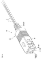
FIG. 1 is a perspective view showing a structure located near an optical connector of an optical fiber cable having a connector of a first embodiment of the present invention. -
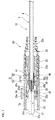
FIG. 2 is a cross-sectional view showing the structure of the optical connector ofFIG. 1 . -
FIG. 3 is an exploded perspective view showing the structure of the optical connector ofFIG. 1 . -
FIGS. 4A and 4B are views illustrating a mounting step of the ferrule in an assembly method of the optical fiber cable having a connector of an embodiment according to the present invention. -
FIG. 5 is a view illustrating a mounting step of the ferrule in the assembly method of the optical fiber cable having the connector of the embodiment according to the present invention. -
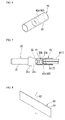
FIG. 6 is a perspective view showing an example of a heat-shrinkable tube with adhesive which is used in a reinforced portion-forming step in the assembly method of the optical fiber cable having the connector of the embodiment according to the present invention. -
FIG. 7 is a view illustrating the reinforced portion-forming step in the assembly method of the optical fiber cable having the connector of the embodiment according to the present invention. -
FIG. 8 is a perspective view showing an example of a heating plate which is used in a reinforced portion-forming step in the assembly method of the optical fiber cable having the connector of the embodiment according to the present invention. -
FIGS. 9A to 9C are perspective views showing another example of the heat-shrinkable tube with adhesive which is used in a reinforced portion-forming step in the assembly method of the optical fiber cable having a connector of the embodiment according to the present invention. -
FIG. 10 is a perspective view showing the structure of an optical fiber cable of the optical fiber cable having the connector ofFIG. 1 . - Hereinafter, an embodiment of the present invention will be described with reference to the drawings.
- As shown in
FIGS. 1 to 3 , in anoptical fiber cable 10 with a connector of the embodiment described herein, anoptical connector 20 is assembled on the tip portion of anoptical fiber cable 1. - As shown in
FIG. 10 , theoptical fiber cable 1 is a tight buffer type optical fiber cable and is configured by collectively coating anoptical fiber 2 and flexible lineartensile strength bodies 3 so as to be parallel to each other using ajacket 4 made of synthetic resin. - For example, as the
tensile strength bodies 3, there may be the strength body which is formed of tensile strength fibers such as an aramid fiber, a steel wire, or the like. Thetensile strength bodies 3 are disposed so as to extend along theoptical fiber 2 in both sides of theoptical fiber 2. - The
optical fiber 2 is an optical fiber with a coating having a configuration in which the outer circumferential surface (side surface) of a bareoptical fiber 2a is covered with acoating 2b. For example, as theoptical fiber 2, there may be an optical fiber core, an optical fiber wire, or the like. For example, the bareoptical fiber 2a is a quartz-based optical fiber. In addition, for example, thecoating 2b is a resin coating in which ultraviolet-curable resin, polyamide resin, or the like is substantially concentrically coated in a single layer or a plurality of layers. - As the
optical fiber cable 1, there may be an indoor cable, a drop cable, or the like. - As shown in
FIGS. 2 and3 , aferrule 30 to which theoptical fiber 2 protruding from the terminal of theoptical fiber cable 1 is inserted and fixed is accommodated in a sleeve-shaped housing 21, and thereby, theoptical connector 20 is schematically configured. - Specifically, the
optical connector 20 of the shown example is assembled using ahousing 21, a knob 22 (coupling), and aboot 23 of a SC type optical connector (SC: Single-fiber Coupling optical fiber connector and an F04 type optical connector which is defined in JISC 5973). Moreover, theoptical connector 20 includes aspring 26 which elastically biases theferrule 30 to the front side of the connector (left side inFIG. 2 ) in thehousing 21. - The
housing 21 is assembled by fitting (fitting into) the front end portion of a sleeve-shaped stop ring 25 to the rear end portion of aplug frame 24 which configures the front side portion of the housing. Theplug frame 24 of theoptical connector 20 of the shown example is formed in an angled tubular shape, and thestop ring 25 is formed in a cylindrical shape. - The
knob 22 is an angled tubular shape and is externally inserted to thehousing 21, and the knob secures a slightly movable range in the axis line direction of thehousing 21 and is slidably assembled. - The
ferrule 30 is a ferrule for a single-core optical connector (here, a SC type optical connector) and has a configuration in which a sleeve-shaped flange part 32 is fixed to a capillary shape ferrulemain body 31. - For example, as a material for forming the ferrule
main body 31, ceramic such as zirconia, or glass may be adopted. Moreover, in the ferrulemain body 31, afiber hole 31a which is a micropore is provided so as be penetrated, and the fiber hole coaxially extends to the center axis line of the ferrulemain body 31 having a cylindrical shape. - For example, as shown in
FIGS. 2 to 4B , theflange part 32 is an integral molded part made of metal. However, the flange part is not limited to the part made of metal, and for example, the flange part may adopt a hard plastic part or the like. Theflange part 32 includes afixing ring portion 32a that is externally inserted to and fixed to the rear end portion opposite to asplice end surface 31b of the front end of the ferrulemain body 31, and asleeve portion 32b that extends from thefixing ring portion 32a to the rear side (the side opposite to thesplice end surface 31b of the ferrule main body 31). Thesleeve portion 32b is formed in a tubular shape that includes aninner hole 32c that is coaxial with thefixing ring portion 32a. Moreover, aflange portion 32d that protrudes over the entire outer circumference is circumferentially provided in the front end portion (the end portion opposite to thesleeve portion 32b) of thefixing ring portion 32a. - The
flange portion 32d functions as a flange portion of theferrule 30. - As shown in
FIG. 2 , theoptical fiber 2 that protrudes from the terminal (tip) of theoptical fiber cable 1, specifically, the bareoptical fiber 2a which is led out at the tip portion of theoptical fiber 2 is inserted into and fixed to thefiber hole 31a of the ferrulemain body 31, and the portion (coated portion) which is covered with thecoating 2b of theoptical fiber 2 is inserted into and fixed to theinner hole 32c of thesleeve portion 32b of theflange part 32. For example, theoptical fiber 2 is bonded and fixed to theferrule 30 by adhesive that is filled in thefiber hole 31a and theinner hole 32c of theferrule 30. Theoptical fiber 2 is inserted into and fixed to a fiberinner insertion hole 33 of theferrule 30 that includes thefiber hole 31a and theinner hole 32c. - In addition, grinding is performed on the
splice end surface 31b of the ferrulemain body 31. The tip (front end) surface of the bareoptical fiber 2a of theoptical fiber 2 is aligned with thesplice end surface 31b of the ferrulemain body 31. The tip surface of the bareoptical fiber 2a is ground at the surface that is continuous to thesplice end surface 31b of the ferrulemain body 31. - The
boot 23 of theoptical connector 20 includes a sleeve-shaped mountingportion 23a that is assembled to the circumference of thestop ring 25 and a taperedtubular portion 23b having flexibility that extends from the frontside sleeve portion 23a to the rear side (the side opposite to the plug frame 24) of thestop ring 25. The taperedtubular portion 23b is formed in a shape which is gradually tapered from the frontside sleeve portion 23a to the rear side. - The
optical fiber cable 1 is drawn inside the taperedtubular portion 23b of theboot 23 and is drawn into thehousing 21 of theoptical connector 20. The tip portion of theoptical fiber cable 1 is disposed so as to be separated from the ferrule 30 (specifically, the rear end of thesleeve portion 32b of the flange part 32) to the rear side. - As shown in
FIG. 2 , theoptical connector 20 includes thesleeve portion 32b of theflange part 32 of theferrule 30, the tip portion of theoptical fiber cable 1, a heat-shrinkable tube 41 that accommodates the sleeve portion and the tip portion, and a reinforcedportion 40 that is integrated by adhesive 42 filled in the inner portion of the heat-shrinkable tube 41 in thehousing 21. - In the heat-
shrinkable tube 41, one end portion in the axis line direction is externally inserted to and fixed to thesleeve portion 32b of theflange part 32 of the ferrule 30 (hereinafter, also referred to as a rearside sleeve portion 32b of the ferrule 30), and the other end portion in the axis line direction is provided so as to be externally inserted to and fixed to the tip portion of theoptical fiber cable 1. - A
protrusion portion 32e that increases pull-out resistance of the heat-shrinkable tube 41 protrudes into the circumference in thesleeve portion 32b of theflange part 32 of theferrule 30. Theprotrusion portion 32e that is exemplified inFIGS. 2 to 4B is formed in a flange shape which extends along the circumferential direction of the outer circumference of thesleeve portion 32b. In addition, theprotrusion portions 32e are formed in a plurality of locations in the axis line direction of thesleeve portion 32b. - The heat-
shrinkable tube 41 that is externally inserted to and fixed to the rearside sleeve portion 32b of theferrule 30 is formed in an unevenshape according to the unevenshape due to the presence of theprotrusion portion 32e on the outer circumference of thesleeve portion 32b, and comes into press-contact with the outer circumference of thesleeve portion 32b. Thereby, the heat-shrinkable tube 41 that is externally inserted to and fixed to the rearside sleeve portion 32b of theferrule 30 increases removing force in the axis line direction from thesleeve portion 32b, and the positional deviation in the axis line direction with respect to thesleeve portion 32b is prevented. - The adhesive 42 (specifically, the resin that is generated due to solidification of the adhesive 42) is filled between the rear
side sleeve portion 32b of the ferrule 30 (the rear end portion of the ferrule 30) and the tip position of theoptical fiber cable 1 that is disposed so as to be separated from the rear side of thesleeve portion 32b. In theoptical fiber 2 that protrudes from theoptical fiber cable 1, a portion (hereinafter, also referred to as an "intermediate extension portion 2c") that extends between theferrule 30 and the optical fiber cable 1 (coating portion that is coated by the jacket 4) is embedded to the adhesive 42 and integrated. - As the adhesive 42, a hot-melt adhesive that includes a hot-melt resin may be appropriately used. In this embodiment, the hot-melt adhesive that includes the hot-melt resin is used as the adhesive 42.
- For example, as the hot-melt resin, there may be ethylene-vinyl acetate copolymer (EVA), polyethylene, polyisobutylene, polyamide, an ethylene-acrylate acid ester copolymer, or the like.
- For example, in the configuration in which the
intermediate extension portion 2c of theoptical fiber 2 of theoptical fiber cable 1 is embedded in the resin that is generated due to the solidification of the adhesive 42 and is integrated, it is possible to prevent external force such as a pulling force which acts from the portion extending from theoptical connector 20 of theoptical fiber cable 1 to the rear side or a displacement force generated due to push back of theferrule 30 at the time of the fitting of the connector from intensively acting on theintermediate extension portion 2c. As a result, buckling, breaking, or the like of theintermediate extension portion 2c does not easily occur, and there is an advantage in that the mechanical durability can be improved. - Moreover, in this configuration, some deformation can be applied to the resin in which the
intermediate extension portion 2c is embedded and integrated. Thereby, for example, when bending stress is applied to the reinforcedportion 40 due to side pull (pulling in the direction along a virtual perpendicular surface which is perpendicular to the axis line of thehousing 21 of the optical connector 20) or the like with respect to theoptical connector 20 of theoptical fiber cable 1, the reinforcedportion 40 is appropriately deformed elastically. Thereby, rupture of thehousing 21 due to local stress concentration can be prevented. - The
spring 26 of theoptical connector 20 is externally inserted to the reinforcedportion 40, and is interposed between the front end of thestop ring 25 and theflange portion 32d of theferrule 30. - The
flange portion 32d of theferrule 30 abuts astopper protrusion 24a, which is provided so as to protrude in the inner surface of theplug frame 24, from the rear side (right side inFIG. 2 ) due to the elastic biasing force of thespring 26. Theferrule 30 resists the elastic biasing force of thespring 26 from the position in which theflange portion 32d abuts thestopper protrusion 24a of theplug frame 24 and can be pushed (pushed back) to the rear side of the connector. - The position in which the
flange portion 32d abuts thestopper protrusion 24a of theplug frame 24 becomes a forward movement limit position of theferrule 30 with respect to thehousing 21. - First, as shown in
FIG. 5 , in the assembly of theoptical fiber cable 10 with the connector (the assembly method of the optical fiber cable having the connector), a ferrule mounting step in which theferrule 30 is mounted on the tip portion of theoptical fiber 2 that protrudes from the terminal of theoptical fiber cable 1 is performed. In the ferrule mounting step, theoptical fiber 2 is inserted into the fiberinner insertion hole 33 of theferrule 30 and is fixed to theferrule 30 by bonding and fixing, or the like. - As shown in
FIGS. 4A and 4B , the tip portion of theoptical fiber cable 1 is disposed so as to be separated from the ferrule 30 (specifically, the rear end of thesleeve portion 32b of the flange part 32) to the rear side. Since the protrusion length of theoptical fiber 2 that protrudes from the terminal of theoptical fiber cable 1 secures a length that is longer than the entire length of the fiberinner insertion hole 33 of theferrule 30, theoptical fiber cable 1 can be disposed at the position that is separated from the rear end of theferrule 30 to the rear side. It is preferable to secure a separation distance C of 1 mm or more between the tip portion of theoptical fiber cable 1 and the rear end of theferrule 30. - Moreover, the
stop ring 25, theboot 23, thespring 26, and the heat-shrinkable tube 43 with adhesive (described below), which are used in the assembly of theoptical connector 20 in the ferrule mounting step, are externally inserted to theoptical fiber cable 1, and are disposed at the position that is separated from the tip portion of theoptical fiber cable 1 so as not to interfere with the work. - However, in a step after the ferrule mounting step, the
stop ring 25, theboot 23, thespring 26, and the heat-shrinkable tube 43 with the adhesive (described below) are externally inserted from the end portion (rear end portion) opposite to the tip portion of theoptical fiber cable 1 to theoptical fiber cable 1 sequentially, and may be used in the assembly of theoptical connector 20. - If the ferrule mounting step has been completed, subsequently, the rear
side sleeve portion 32b of theferrule 30 and the tip portion of theoptical fiber cable 1 are accommodated inside the heat-shrinkable tube 41, and the step of forming the reinforced portion 40 (reinforced portion-forming step) is performed. - As shown in
FIG. 6 , in the reinforced portion-forming step (the step of forming the reinforced portion), the heat-shrinkable tube 43 with the adhesive in which the hot-melt adhesive 42 is provided in a ring shape is used along the inner surface of the center portion in the longitudinal direction of the cylindrical heat-shrinkable tube 41. The hot-melt adhesive 42 is coated with the inner surface of the heat-shrinkable tube 41 of the hot-melt resin which is heated and melted, or the hot-melt resin is fitted inside the heat-shrinkable tube 41 in advance which is a resin ring formed in a ring shape, and the hot-melt adhesive is provided in the heat-shrinkable tube 41 by thermal welding, the bonding and fixing using separate adhesive, or the like. Hereinafter, the hot-melt adhesive 42, which provided in a ring shape along the inner surface in the heat-shrinkable tube 41, is also referred to as a ring-shapedadhesive layer 42a. - As the heat-
shrinkable tube 41, a tube which includes a heat shrinkage resin is used, and for example, a polyolefin which shrinks at 100 to 160 °C, or the like may be used. - As the hot-
melt adhesive 42, adhesive which is melted at the shrinkage temperature of the heat-shrinkable tube 41 is used. For example, the melting temperature is 100 to 160 °C. - In the reinforced portion-forming step, the heat-
shrinkable tube 43 with the adhesive which is externally inserted to theoptical fiber cable 1 is moved in the longitudinal direction of theoptical fiber cable 1, and as shown inFIG. 7 , the heat-shrinkable tube 43 with the adhesive is coated (externally inserted) between the rearside sleeve portion 32b of theferrule 30 and the tip portion of theoptical fiber cable 1. In addition, at this time, the heat-shrinkable tube 43 with the adhesive is disposed so that the ring-shapedadhesive layer 42a coats the entireintermediate extension portion 2c. The heat-shrinkable tube 43 with the adhesive uses a tube that includes the ring-shapedadhesive layer 42a that is formed in the size capable of covering the entireintermediate extension portion 2c. - In the ring-shaped
adhesive layer 42a of the heat-shrinkable tube 43 with the adhesive of the example shown inFIG. 7 , the length of the ring-shapedadhesive layer 42a in the axis line direction of the heat-shrinkable tube 41 is formed so as to be slightly longer compared to the length in the axis line direction of theintermediate extension portion 2c, and is formed so as to be shorter compared to the length in the axis line direction of the heat-shrinkable tube 41. The heat-shrinkable tube 41 includes the inner surface, which is not covered with the ring-shapedadhesive layer 42, in both sides via the ring-shapedadhesive layer 42a which is formed only in the center portion in the axis line direction. - Subsequently, in the reinforced portion-forming step, the heat-
shrinkable tube 43 with the adhesive is heated to a temperature which is equal to or more than the shrinkage temperature of the heat-shrinkable tube 41. Thereby, the heat-shrinkable tube 41 is shrunk and the hot-melt adhesive 42 which is melted is embedded between the rearside sleeve portion 32b of theferrule 30 and the tip portion of theoptical fiber cable 1. Theintermediate extension portion 2c of theoptical fiber 2 of theoptical fiber cable 1 is embedded into the hot-melt adhesive 42. - Subsequently, the temperature of the heat-
shrinkable tube 43 with the adhesive is decreased to the temperature which is lower than the melting temperature of the hot-melt adhesive 42 by air cooling or the like, and the hot-melt adhesive 42 is solidified. Thereby, the rearside sleeve portion 32b of theferrule 30, the tip portion of theoptical fiber cable 1, and the heat-shrinkable tube 41 are firmly adhered by the hot-melt adhesive 42 and are integrated, and the reinforcedportion 40 can be formed. The reinforced portion-forming step is completed according to the formation of the reinforcedportion 40. In addition, in the formed reinforcedportion 40, theintermediate extension portion 2c of theoptical fiber 2 of theoptical fiber cable 1 is also integrated by the hot-melt adhesive 42. - The heat-
shrinkable tube 41 becomes pressure-bonded to both of the rearside sleeve portion 32b of theferrule 30 and the tip portion of theoptical fiber cable 1 due to the heating and shrinkage. - Moreover, in the reinforced forming step, for example, liquid adhesive such as epoxy-based adhesive is coated with the inner surface of the portion of the heat-
shrinkable tube 43 with the adhesive which is externally inserted to the rearside sleeve portion 32b of theferrule 30 and the inner surface of the portion of the heat-shrinkable tube 43 with the adhesive which is externally inserted to the tip portion of theoptical fiber cable 1, and the heat-shrinkable tube 43 with the adhesive may be used. The liquid adhesive is coated with the inner surfaces of both sides (the inner surfaces which are not coated with the ring-shapedadhesive layer 42a) via the ring-shapedadhesive layer 42a of the center portion in the longitudinal direction of the heat-shrinkable tube 41. Thereby, the fixing force of the heat-shrinkable tube 41 with respect to the rearside sleeve portion 32b of theferrule 30 and the tip portion of theoptical fiber cable 1 can increase. - As exemplified in
FIG. 7 , in the reinforced portion-forming step, from the viewpoints of the shape stabilization of the reinforcedportion 40, it is preferable that the heat-shrinkable tube 43 with the adhesive be heated in a state where one side near (both end portions in the axis line direction) the end surfaces of both ends in the axis line direction of the ring-shapedadhesive layer 42a is externally inserted to the rearside sleeve portion 32b of theferrule 30 and the other side is externally inserted to the tip portion of theoptical fiber cable 1. - For example, the heat-
shrinkable tube 43 with the adhesive is disposed in a state where the ring-shapedadhesive layer 42a is externally inserted only to theintermediate extension portion 2c and may be heated. However, compared to the state where the ring-shapedadhesive layer 42a is externally inserted only to theintermediate extension portion 2c, in the case where the heat-shrinkable tube 43 with the adhesive is disposed with respect to the rearside sleeve portion 32b of theferrule 30 and the tip portion of theoptical fiber cable 1 ofFIG. 7 , it is possible to stabilize the shape of the reinforcedportion 40 which is formed by the heating of the heat-shrinkable tube 43 with the adhesive. In addition, as exemplified inFIG. 7 , from the viewpoints of the shape stabilization of the reinforcedportion 40, it is preferable that the heat-shrinkable tube 43 with the adhesive be heated in a state where one end portion in the axis line direction of the ring-shapedadhesive layer 42a is externally inserted to the rear end portion of the rearside sleeve portion 32b of theferrule 30 and the other end portion is externally inserted to the near tip surface of thejacket 4 of theoptical fiber cable 1. - The cause of this needs further verification. However, a deaeration property from the inner side of the heat-
shrinkable tube 41 according to the heating and shrinkage of the heat-shrinkable tube 41 is assumed as one cause. - In the case where the ring-shaped
adhesive layer 42a is externally inserted only to theintermediate extension portion 2c, when the heat-shrinkable tube 43 with the adhesive is heated and the heat-shrinkable tube 41 is shrunk, the shrinkage of the portion of the heat-shrinkable tube 41 which is externally inserted to theintermediate extension portion 2c progresses even after the heat-shrinkable tube 41 becomes pressure-bonded to the rearside sleeve portion 32b of theferrule 30 and the tip portion of theoptical fiber cable 1. If the heat-shrinkable tube 41 comes into press-contact with the rearside sleeve portion 32b of theferrule 30 and the tip portion of theoptical fiber 1, the deaeration property from the inner portion of the heat-shrinkable tube 41 is decreased. Thereby, thereafter, if the shrinkage of the portion of the heat-shrinkable tube 41 which is externally inserted to theintermediate extension portion 2c progresses, a phenomenon occurs in which air that reaches a high pressure inside the heat-shrinkable tube 41 partially expands and moves the heat-shrinkable tube 41 forcibly. Moreover, it is considered that the phenomenon is one of the causes which makes the shape of the reinforcedportion 40 be unstable. - In contrast, in the case of the disposition of
FIG. 7 , when the heat-shrinkable tube 43 with the adhesive is heated and the heat-shrinkable tube 41 is shrunk, as much of the distance from the rearside sleeve portion 32b of theferrule 30 and the tip portion of theoptical fiber cable 1 to the heat-shrinkable tube 41 increases, the shrinkage of the portion of the heat-shrinkable tube 41 which is externally inserted to theintermediate extension portion 2c progresses to some extent before the heat-shrinkable tuber 41 comes into press-contact with the rearside sleeve portion 32b of theferrule 30 and the tip portion of theoptical fiber cable 1. Compared to the case where the ring-shapedadhesive layer 42a is externally inserted only to theintermediate extension portion 2c, when the heat-shrinkable tuber 41 comes into press-contact with the rearside sleeve portion 32b of theferrule 30 and the tip portion of theoptical fiber cable 1, the shrinkage of the portion of the heat-shrinkable tube 41 which is externally inserted to theintermediate extension portion 2c greatly progresses. Thereby, in the case of the disposition ofFIG. 7 , before the heat-shrinkable tube 41 comes into press-contact with the rearside sleeve portion 32b of theferrule 30 and the tip portion of theoptical fiber cable 1, the air inside the portion has been pushed to some extent already due to the shrinkage of the portion of the heat-shrinkable tube 41 which is externally inserted to theintermediate extension portion 2c. Therefore, in the case of the disposition ofFIG. 7 , compared to the case where the ring-shapedadhesive layer 42a is externally inserted only to theintermediate extension portion 2c, occurrence of the phenomenon in which the air that reaches a high pressure inside the heat-shrinkable tube 41 partially expands and moves the heat-shrinkable tube 41 forcibly is suppressed, and it is considered that the stabilization of the shape of the reinforcedportion 40 can increase. - The heating of the overall heat-
shrinkable tube 43 with the adhesive can be equally performed. However, for example, the heating may use aheating plate 50 exemplified inFIG. 8 . - In the
heating plate 50 exemplified inFIG. 8 , an electrically-heated wire 52 is mounted along the width direction perpendicular to the longitudinal direction of the side surface in the center portion in the longitudinal direction of the side surface of an elongate plate-shapedmetal plate 51. An electric current flows to the electrically-heated wire 52 and themetal plate 51 is heated, and thereby, theheating plate 50 can propagate the heat from the center portion in the longitudinal direction of themetal plate 51 toward the both ends in the longitudinal direction. - In the heating of the heat-
shrinkable tube 43 with the adhesive using theheating plate 50, the longitudinal direction of themetal plate 51 is arranged in the axis line direction (longitudinal direction) of the elongated heat-shrinkable tube 41, and the surface opposite to the rear surface on which the electrically-heated wire 52 of themetal plate 51 is disposed abuts the outer circumferential surface of the heat-shrinkable tube 41. Moreover, in theheating plate 50, when the surface of themetal plate 51 abuts the outer circumferential surface of the heat-shrinkable tube 41, the disposed position of the electrically-heated wire 52 of the center portion in the longitudinal direction of themetal plate 51 is positioned in the center portion in the axial direction of the portion of the heat-shrinkable tube 41 which is externally inserted to theintermediate extension portion 2c. Thereby, due to the fact that an electric current flows to the electrically-heated wire 52 and themetal plate 51 is heated, the heating of the heat-shrinkable tube 43 with the adhesive progresses from the center portion in the axis line direction of the portion of the heat-shrinkable tube 41 which is externally inserted to theintermediate extension portion 2c toward both ends in the axis line direction. As a result, melting of the ring-shapedadhesive layer 42a and the shrinkage of the heat-shrinkable tube 41 progresses from the center portion in the axis line direction of the portion of the heat-shrinkable tube 41 which is externally inserted to theintermediate extension portion 2c toward both ends in the axis line direction, which effectively contributes to a smooth discharge of the air from the inner side of the heat-shrinkable tube 41. - The
heating plate 50 exemplified inFIG. 8 has the configuration in which the elongate plate-shapedmetal plate 51 is used. However, for example, the heating plate may adopt a configuration in which an arcuate plate-shaped metal plate bent with a curvature which substantially conforms to the outer circumference of the heat-shrinkable tube 41 is used instead of the elongate plate-shapedmetal plate 51. - The length and the externally inserted position with respect to the
optical fiber cable 1 of the heat-shrinkable tube 41 of the heat-shrinkable tube 43 with the adhesive are adjusted so that the heat-shrinkable tube 41 does not protrude from the rear end (the rear end of the stop ring 25) of thehousing 21 of theoptical connector 20 assembled in the later step in the rear side. - In
FIG. 2 , in the heat-shrinkable tube 41 (the heat-shrinkable tube 41 which configures a portion of the reinforced portion 40), the rear end opposite to the front end of theferrule 30 side is positioned in the center portion in the longitudinal direction of thestop ring 25. For example, in the heat-shrinkable tube 41, the length thereof is further lengthened compared to the example ofFIG. 2 within a range in which the rear end does not protrude from the rear end of thestop ring 25 in the rear side, and the rear end may be disposed near the rear end of thestop ring 25. - If the reinforced portion-forming step is completed, the
housing 21 of theoptical connector 20 is assembled and theferrule 30 is accommodated in the housing 21 (housing assembling step). - In the housing assembling step, the
ferrule 30 is inserted into theframe 24, thestop ring 25, theboot 23, and thespring 26 which are externally inserted to theoptical fiber cable 1 are moved in the front side (ferrule 30 side) along the longitudinal direction of theoptical fiber cable 1, the front end portion of thestop ring 25 is fitted (specifically, internally fitted) to theplug frame 24 and is assembled, and thehousing 21 is assembled. - As shown in
FIG. 3 , lockingholes 24b to whichengagement protrusions 25a protruding in both sides of the front end portion of thestop ring 25 are fitted are formed on both sides of the rear end portion of theplug frame 24. The front end portion of thestop ring 25 is inserted from the rear end of theplug frame 24 to the inner side of theplug frame 24, theengagement protrusions 25a of both sides of the front end portion are fitted to the locking holes 24b of both sides of the rear end portion of theplug frame 24, and thestop ring 25 is fitted to theplug frame 24 and fixed thereto. - Moreover, in the housing assembling step, the
knob 22 is externally inserted into thehousing 21 from the front side and assembled after the assembly of thehousing 21. - In addition, in the housing assembling step, grinding of the tip (front end) of the ferrule main body 31 (grinding step) is performed in a state where the assembly of the
housing 21 is completed (a state where theknob 22 is not assembled) or a state where the assembly of theknob 22 is also completed. Thereby, along with thesplice end surface 31b of the ferrulemain body 31, the tip surface of theoptical fiber 2 which is inserted into and fixed to the ferrulemain body 31 also becomes a grinding surface which is continuous to thesplice end surface 31b. - The
boot 23 is externally inserted to theoptical fiber cable 1 in a state where the boot is assembled to thestop ring 25 in advance and is moved to the front side along with thestop ring 25 in the housing assembling step or theboot 23 is externally inserted to theoptical fiber cable 1 in a state where the boot is not assembled to thestop ring 25 and is assembled to thestop ring 25 in the housing assembling step. - If the housing assembling step that includes the grinding step is completed, the assembly of the
optical fiber cable 10 with the connector is completed. - In the
optical fiber cable 10 with the connector, since the reinforcedportion 40 in theoptical connector 20 has the configuration in which the rearside sleeve portion 32b of theferrule 30, the tip portion of theoptical fiber cable 1, and the heat-shrinkable tube 41 are integrated, mechanical strength between the rearside sleeve portion 32b of theferrule 30 and the tip portion of theoptical fiber cable 1 can be easily secured. The structure of the reinforcedportion 40 is simple, and the reinforcedportion 40 can be simply assembled at a low cost. Moreover, since a decrease in the size of the reinforcedportion 40 is easily achieved, an influence on the size of the connector can be avoided. Like the shown example, theoptical connector 20 of theoptical fiber cable 10 with the connector can be assembled using the housing of a SC type optical connector. - In addition, since the
optical connector 20 has the structure in which theoptical fiber 2 protruding from the terminal of theoptical fiber cable 1 is directly inserted into theferrule 30 and fixed, compared to a field assembly type optical connector, the connecting points of the optical fiber are decreased. Since it is not necessary to accommodate the connecting points and anchoring means for anchoring the optical fiber cable is not required in theoptical connector 20, the structure is simple, the entire length of the connector can be suppressed, and low costs are easily realized. - The
optical fiber cable 1 of theoptical fiber cable 10 with the connector freely inserts into theboot 23 of theoptical connector 20 and can move in the axis line direction with respect to theboot 23. Theoptical fiber cable 1 can move in the axis line direction with respect to thehousing 21. Thereby, for example, in theoptical fiber cable 10 with the connector, when a pulling force toward the rear side with respect to theoptical connector 20 acts on theoptical fiber cable 1, theoptical fiber cable 1, theferrule 30, and the reinforcedportion 40 are integrally displaced to the rear side with respect to thehousing 21 of theoptical connector 20. Moreover, in theoptical fiber cable 10 with the connector, also when theferrule 30 is pushed back at the time of the connector fitting of theoptical connector 20, theoptical fiber cable 1, theferrule 30, and the reinforcedportion 40 are integrally displaced to the rear side with respect to thehousing 21 of theoptical connector 20. - The
optical fiber cable 10 with the connector is securely connected by the reinforcedportion 40 between theferrule 30 and theoptical fiber cable 1 and is integrated. Thereby, in theoptical fiber cable 10 with the connector, when the pulling force toward the rear side with respect to theoptical connector 20 acts on theoptical fiber cable 1 or theferrule 30 is pushed back, it is possible to prevent the forces such as pulling and bending from intensively acting on theintermediate extension portion 2c of theoptical fiber 2 of theoptical fiber cable 1. Therefore, it is possible to prevent theintermediate extension portion 2c of theoptical fiber 2 of theoptical fiber cable 1 from being damaged due to the external force such as the pulling. - In the
optical fiber cable 10 with the connector, since the reinforcedportion 40 can secure high mechanical strength, for example, even in the use condition in which a relatively strong pulling force acts such as a drop cable, an optical property can be stably secured, and sufficient durability can be obtained. -
FIGS. 9A to 9C are cross-sectional perspective views showing modifications of the heat-shrinkable tube 43 with the adhesive. - As shown in
FIGS. 9A to 9C , as the heat-shrinkable tube 43 with the adhesive, a configuration may be also adopted in whichtensile strength fibers 44 which extends in the axis line direction of the heat-shrinkable tube 41 is substantially equally disposed in the circumferential direction of the heat-shrinkable tube 41. - For example, as the
tensile strength fibers 44, an aramid fiber can be appropriately used. However, the tensile strength fibers are not limited thereto, and for example, a glass fiber, a carbon fiber, or the like can be also used. - In the heat-shrinkable tube 43 (a
reference numeral 43A is added) with the adhesive exemplified inFIG. 9A , thetensile strength fibers 44 is interposed between the heat-shrinkable tube 41 and the ring-shapedadhesive layer 42a and is provided in the heat-shrinkable tube 41 in the direction which extends along the axis line direction. Thetensile strength fibers 44 are provided in both sides opposite to each other via the center axis line of the cylindrical heat-shrinkable tube 41. - In the heat-shrinkable tube 43 (a
reference numeral 43B is added) with the adhesive exemplified inFIG. 9B , the number of thetensile strength fibers 44 of the heat-shrinkable tube 43A with the adhesive exemplified inFIG. 9A increases, and thetensile strength fibers 44 are substantially equally disposed in a plurality of locations in the circumferential direction of the cylindrical heat-shrinkable tube 41. - In the heat-shrinkable tube 43 (a
reference numeral 43C is added) with the adhesive exemplified inFIG. 9C , the heat-shrinkable tube 41A having the configuration in which thetensile strength fibers 44 extending along the axis line direction of the above-described heat-shrinkable tube 41 is embedded to the heat-shrinkable tube 41 is adopted as the heat-shrinkable tube. Thetensile strength fibers 44 are substantially equally disposed in a plurality of locations in the circumferential direction of the cylindrical heat-shrinkable tube 41A. - The reinforced
portion 40, which is formed using the heat-shrinkable tube 43 with the adhesive having the configuration in which thetensile strength fibers 44 is provided, has the configuration in which thetensile strength fibers 44 extends along the front and rear directions (the axis line direction of the housing 21) of the connector. The reinforcedportion 40, which is formed using the heat-shrinkable tube tensile strength fibers 44 is disposed inside the heat-shrinkable tube 41, has the configuration in which thetensile strength fibers 44 is embedded into the hot-melt adhesive 42 in the heat-shrinkable tube 41 which is heated and shrunk and is integrated. - The reinforced
portion 40, which is formed using the heat-shrinkable tube 43 with the adhesive having the configuration in which thetensile strength fibers 44 is provided, provides a function which increases the strength with respect to the external force such as the pulling force or the bending stress in which thetensile strength fibers 44 acts on the reinforcedportion 40. - As described above, the present invention is described based on the best mode. However, the present invention is not limited to the above-described best mode and various modifications are possible within the scope which does not depart from the gist of the present invention.
- For example, the specific configuration of the optical connector is not limited at all as long as the configuration conforms to the technical idea of the present invention. The specific steps which assemble the optical connector can be also modified according to the specific configuration of the optical connector. The optical connector includes the ferrule and the housing which accommodates the ferrule. However, the optical connector may also adopt a connector in which the knob is not provided.
- While preferred embodiments of the invention have been described and illustrated above, it should be understood that these are exemplary of the invention and are not to be considered as limiting. Additions, omissions, substitutions, and other modifications can be made without departing from the scope of the present invention. Accordingly, the invention is not to be considered as being limited by the foregoing description, and is only limited by the scope of the appended claims.
Claims (7)
- An optical fiber cable having an optical connector, comprising:an optical connector assembled on a tip portion of an optical fiber cable, comprising a ferrule in which an optical fiber protruding from a terminal of the optical fiber cable is inserted and fixed; anda reinforced portion formed by heating and shrinking a heat-shrinkable tube and by so solidifying a hot-melt adhesive of an inner portion of the heat-shrinkable tube after melting the hot-melt adhesive so as to integrate a rear end portion of the ferrule, the tip portion of the optical fiber cable which is disposed so as to be separated in a rear side of the ferrule, and the heat-shrinkable tube which accommodates the rear end portion of the ferrule and the tip portion of the optical fiber cable and in which the hot-melt adhesive is disposed in the inner portion of the heat-shrinkable tube.
- The optical fiber cable having the connector according to Claim 1, further comprising a protrusion portion formed in the rear end portion of the ferrule, increasing pull-out resistance of the heat-shrinkable tube.
- The optical fiber cable having the connector according to Claim 1 or 2, further comprising tensile strength fibers disposed inside the heat-shrinkable tube or embedded to the heat-shrinkable tube, substantially equally disposed in a plurality of locations in a circumferential direction of the heat-shrinkable tube, extending along an axis line direction of the heat-shrinkable tube.
- An assembly method of an optical fiber cable having a connector, comprising:a step of inserting and fixing an optical fiber protruding from a terminal of an optical fiber cable into a ferrule;a step of accommodating a rear end portion of an inserted and fixed ferrule and a tip portion of the optical fiber cable which is disposed so as to be separated in a rear side of the ferrule into a heat-shrinkable tube in which a hot-melt adhesive is disposed in an inner portion of the heat-shrinkable tube in advance, anda step of forming a reinforced portion, integrating a rear end portion of the ferrule, the tip portion of the optical fiber cable, and the heat-shrinkable tube by heating and shrinking an accommodating heat-shrinkable tube and by solidifying the hot-melt adhesive in the heat-shrinkable tube after melting the hot-melt adhesive.
- The assembly method of the optical fiber cable having the connector according to Claim 4, wherein using a ferrule in which a protrusion portion which increases pull-out resistance of the heat-shrinkable tube, and the protrusion portion is formed in the rear end portion of the ferrule.
- The assembly method of the optical fiber cable having the connector according to Claim 4 or 5, wherein
the heat-shrinkable tube is used in which tensile strength fibers extending along an axis line direction of the heat-shrinkable tube are disposed inside the heat-shrinkable tube or embedded to the heat-shrinkable tube, the tensile strength fibers are substantially equally disposed in a plurality of locations in a circumferential direction of the heat-shrinkable tube;
the rear end portion of the ferrule and the tip portion of the optical fiber cable are accommodated inside the heat-shrinkable tube so that the tensile strength fibers are disposed at a periphery of the rear end portion of the ferrule and the tip portion of the optical fiber cable; and
the heat-shrinkable tube is heated and shrunk. - The assembly method of the optical fiber cable having the connector according to any one of Claims 4 to 6, wherein
the heat-shrinkable tube is used in which the hot-melt adhesive is provided in a ring shape along an inner surface of a center portion in a longitudinal direction of the heat-shrinkable tube;
the rear end portion of the ferrule and the tip portion of the optical fiber cable are accommodated inside the hot-melt adhesive; and
the heat-shrinkable tube is heated and shrunk.
Applications Claiming Priority (2)
| Application Number | Priority Date | Filing Date | Title |
|---|---|---|---|
| JP2011259495A JP2013114001A (en) | 2011-11-28 | 2011-11-28 | Optical fiber cable with connector, assembly method of optical fiber cable with connector |
| PCT/JP2012/080492 WO2013080923A1 (en) | 2011-11-28 | 2012-11-26 | Optical fiber cable with attached connector, and method of assembling optical fiber cable with attached connector |
Publications (3)
| Publication Number | Publication Date |
|---|---|
| EP2770355A1 true EP2770355A1 (en) | 2014-08-27 |
| EP2770355A4 EP2770355A4 (en) | 2015-08-26 |
| EP2770355B1 EP2770355B1 (en) | 2017-07-19 |
Family
ID=48535379
Family Applications (1)
| Application Number | Title | Priority Date | Filing Date |
|---|---|---|---|
| EP12853670.3A Not-in-force EP2770355B1 (en) | 2011-11-28 | 2012-11-26 | Optical fiber cable with attached connector, and method of assembling optical fiber cable with attached connector |
Country Status (8)
| Country | Link |
|---|---|
| US (1) | US9239435B2 (en) |
| EP (1) | EP2770355B1 (en) |
| JP (1) | JP2013114001A (en) |
| CN (1) | CN103959118B (en) |
| IN (1) | IN2014CN03677A (en) |
| SA (1) | SA112340030B1 (en) |
| TW (1) | TWI497143B (en) |
| WO (1) | WO2013080923A1 (en) |
Families Citing this family (14)
| Publication number | Priority date | Publication date | Assignee | Title |
|---|---|---|---|---|
| JP2013114001A (en) * | 2011-11-28 | 2013-06-10 | Fujikura Ltd | Optical fiber cable with connector, assembly method of optical fiber cable with connector |
| US9961757B2 (en) * | 2016-05-13 | 2018-05-01 | Ion Beam Applications S.A. | Peripheral hill sector design for cyclotron |
| US9885843B2 (en) | 2016-05-31 | 2018-02-06 | Corning Optical Communications LLC | Forming a fiber bulge in an optical fiber end for positioning the optical fiber in a ferrule bore |
| JP2018010292A (en) * | 2016-06-29 | 2018-01-18 | Toto株式会社 | Optical Receptacle and Optical Transceiver |
| WO2018003940A1 (en) * | 2016-06-29 | 2018-01-04 | Toto株式会社 | Optical receptacle and optical transceiver |
| CN108942133A (en) * | 2017-05-18 | 2018-12-07 | 泰科电子(上海)有限公司 | Package system |
| US11480751B2 (en) * | 2017-07-31 | 2022-10-25 | Commscope Technologies Llc | Optical fiber cable fanout arrangements, components, and methods |
| KR102326928B1 (en) * | 2019-09-25 | 2021-11-16 | 유씨엘 주식회사 | Optical connector plug for field assembly waterproof for outdoor use and its outside assemblying process |
| US11611180B2 (en) | 2020-06-19 | 2023-03-21 | Corning Optical Communications Rf Llc | Coaxial cable connector assemblies with contained adhesives and methods for using the same |
| CN114137667B (en) * | 2021-11-05 | 2023-01-31 | 烽火通信科技股份有限公司 | Prefabricated optical cable connector assembly, manufacturing method and tool |
| WO2023092335A1 (en) * | 2021-11-24 | 2023-06-01 | 华为技术有限公司 | Connector |
| JP7300770B1 (en) * | 2022-03-31 | 2023-06-30 | 株式会社精工技研 | Optical fiber cable with optical connector, method for manufacturing optical fiber cable with optical connector, optical connector |
| JP7300778B1 (en) | 2022-08-09 | 2023-06-30 | 株式会社精工技研 | Optical fiber cable with optical connector, method for manufacturing optical fiber cable with optical connector, optical connector |
| CN117824719B (en) * | 2024-01-05 | 2025-02-28 | 重庆大学 | Liquid metal fiber grating sensor array and its protection device and construction method |
Family Cites Families (17)
| Publication number | Priority date | Publication date | Assignee | Title |
|---|---|---|---|---|
| US4198119A (en) * | 1978-09-13 | 1980-04-15 | International Business Machines Corporation | Connector for optical cable |
| JPS6086508A (en) | 1983-10-17 | 1985-05-16 | Sumitomo Electric Ind Ltd | Fitting part of terminal plug of optical fiber covered with sheath |
| JPH01167813A (en) * | 1987-12-24 | 1989-07-03 | Ube Nitto Kasei Co Ltd | Method for integrating optical fiber and ferrule |
| JP3105477B2 (en) | 1997-08-12 | 2000-10-30 | 株式会社カイジョー | Wire bonding equipment |
| JP2000241662A (en) * | 1999-02-22 | 2000-09-08 | Seiko Instruments Inc | Optical connector and method of manufacturing optical connector |
| US8550728B2 (en) * | 2007-02-13 | 2013-10-08 | Fujikura Ltd. | Method connecting optical fiber of optical connector with optical transmission element, connector-attached optical transmission element, optical connector, and assembling method of optical connector |
| US20080193089A1 (en) * | 2007-02-13 | 2008-08-14 | Fujikura Ltd. | Optical connector connecting method and structure |
| JP2009086267A (en) | 2007-09-28 | 2009-04-23 | Sumiden High Precision Co Ltd | Optical connector |
| JP4719755B2 (en) * | 2008-02-29 | 2011-07-06 | 住友電気工業株式会社 | Optical connector |
| JP5401090B2 (en) | 2008-12-22 | 2014-01-29 | 株式会社フジクラ | Optical fiber connector and optical fiber connection method using the same |
| JP5427445B2 (en) | 2009-03-23 | 2014-02-26 | 株式会社フジクラ | Optical transmission body with connector, optical connector, and optical connector assembly method |
| JP2010256703A (en) | 2009-04-27 | 2010-11-11 | Suncall Corp | Optical connector |
| JP5117449B2 (en) | 2009-06-19 | 2013-01-16 | 古河電気工業株式会社 | Optical cable assembly |
| JP2011075829A (en) * | 2009-09-30 | 2011-04-14 | Fujikura Ltd | Optical transmission member with connector and optical connector |
| JP5401274B2 (en) * | 2009-11-20 | 2014-01-29 | 株式会社フジクラ | Optical transmission body with connector, optical connector, and optical connector assembly method |
| WO2011087093A1 (en) * | 2010-01-14 | 2011-07-21 | 株式会社フジクラ | Optical connector, assembly method for optical connector, reinforcement method for fusion-spliced section, pin clamp, optical connector having cap, cap for optical connector, assembly tools for optical connector and optical connector assembly set |
| JP2013114001A (en) * | 2011-11-28 | 2013-06-10 | Fujikura Ltd | Optical fiber cable with connector, assembly method of optical fiber cable with connector |
-
2011
- 2011-11-28 JP JP2011259495A patent/JP2013114001A/en active Pending
-
2012
- 2012-11-23 TW TW101143924A patent/TWI497143B/en not_active IP Right Cessation
- 2012-11-26 SA SA112340030A patent/SA112340030B1/en unknown
- 2012-11-26 WO PCT/JP2012/080492 patent/WO2013080923A1/en not_active Ceased
- 2012-11-26 EP EP12853670.3A patent/EP2770355B1/en not_active Not-in-force
- 2012-11-26 IN IN3677CHN2014 patent/IN2014CN03677A/en unknown
- 2012-11-26 CN CN201280058548.0A patent/CN103959118B/en not_active Expired - Fee Related
-
2014
- 2014-05-21 US US14/283,402 patent/US9239435B2/en active Active
Also Published As
| Publication number | Publication date |
|---|---|
| EP2770355B1 (en) | 2017-07-19 |
| JP2013114001A (en) | 2013-06-10 |
| US20140254989A1 (en) | 2014-09-11 |
| TWI497143B (en) | 2015-08-21 |
| CN103959118A (en) | 2014-07-30 |
| SA112340030B1 (en) | 2016-03-27 |
| CN103959118B (en) | 2016-01-20 |
| EP2770355A4 (en) | 2015-08-26 |
| TW201329551A (en) | 2013-07-16 |
| IN2014CN03677A (en) | 2015-09-25 |
| WO2013080923A1 (en) | 2013-06-06 |
| US9239435B2 (en) | 2016-01-19 |
Similar Documents
| Publication | Publication Date | Title |
|---|---|---|
| US9239435B2 (en) | Optical fiber cable having connector and assembling method thereof | |
| JP5685298B2 (en) | Optical fiber cable with connector, assembly method of optical fiber cable with connector | |
| US9256035B2 (en) | Optical fiber connector | |
| US8550728B2 (en) | Method connecting optical fiber of optical connector with optical transmission element, connector-attached optical transmission element, optical connector, and assembling method of optical connector | |
| CN101978300B (en) | Optical connector | |
| EP2378331B1 (en) | Method for assembling optical connector | |
| JP5401274B2 (en) | Optical transmission body with connector, optical connector, and optical connector assembly method | |
| WO2009117060A1 (en) | Fusion-splice fiber optic connectors and related tools | |
| JP2011075829A (en) | Optical transmission member with connector and optical connector | |
| CN105659130A (en) | Optical fiber connector, optical fiber connector and optical cable assembly and method of manufacture | |
| JP6419138B2 (en) | Optical fiber cord with connector | |
| JP5427446B2 (en) | Optical transmission body with connector, optical connector, and optical connector assembly method | |
| JP5427445B2 (en) | Optical transmission body with connector, optical connector, and optical connector assembly method | |
| CN102301265B (en) | Optical connector and method for assembling the optical connector | |
| JP5398450B2 (en) | Optical transmission body with connector, optical connector, and optical connector assembly method | |
| JP4812652B2 (en) | Optical connector | |
| JP2020056911A (en) | Optical connector unit | |
| JP2013134457A (en) | Multi-fiber optical connector and assembly method of multi-fiber optical connector | |
| JP4117797B2 (en) | Optical connector assembly and manufacturing method thereof | |
| JP5276905B2 (en) | Optical fiber with connector and method of assembling optical connector | |
| CN113874770B (en) | Optical fiber connector with rear cover | |
| JP2010039109A (en) | Optical connector and assembling method therefor | |
| CN104781710B (en) | For terminating the terminal assemblies of optical cable | |
| JP2010286710A (en) | Optical connector component and optical connector | |
| JP2010107922A (en) | Optical connector plug |
Legal Events
| Date | Code | Title | Description |
|---|---|---|---|
| PUAI | Public reference made under article 153(3) epc to a published international application that has entered the european phase |
Free format text: ORIGINAL CODE: 0009012 |
|
| 17P | Request for examination filed |
Effective date: 20140523 |
|
| AK | Designated contracting states |
Kind code of ref document: A1 Designated state(s): AL AT BE BG CH CY CZ DE DK EE ES FI FR GB GR HR HU IE IS IT LI LT LU LV MC MK MT NL NO PL PT RO RS SE SI SK SM TR |
|
| DAX | Request for extension of the european patent (deleted) | ||
| RA4 | Supplementary search report drawn up and despatched (corrected) |
Effective date: 20150728 |
|
| RIC1 | Information provided on ipc code assigned before grant |
Ipc: G02B 6/38 20060101AFI20150722BHEP Ipc: G02B 6/44 20060101ALN20150722BHEP |
|
| 17Q | First examination report despatched |
Effective date: 20160609 |
|
| REG | Reference to a national code |
Ref country code: DE Ref legal event code: R079 Ref document number: 602012034867 Country of ref document: DE Free format text: PREVIOUS MAIN CLASS: G02B0006360000 Ipc: G02B0006380000 |
|
| GRAP | Despatch of communication of intention to grant a patent |
Free format text: ORIGINAL CODE: EPIDOSNIGR1 |
|
| STAA | Information on the status of an ep patent application or granted ep patent |
Free format text: STATUS: GRANT OF PATENT IS INTENDED |
|
| RIC1 | Information provided on ipc code assigned before grant |
Ipc: G02B 6/38 20060101AFI20170126BHEP Ipc: G02B 6/44 20060101ALN20170126BHEP |
|
| INTG | Intention to grant announced |
Effective date: 20170209 |
|
| GRAS | Grant fee paid |
Free format text: ORIGINAL CODE: EPIDOSNIGR3 |
|
| GRAA | (expected) grant |
Free format text: ORIGINAL CODE: 0009210 |
|
| STAA | Information on the status of an ep patent application or granted ep patent |
Free format text: STATUS: THE PATENT HAS BEEN GRANTED |
|
| AK | Designated contracting states |
Kind code of ref document: B1 Designated state(s): AL AT BE BG CH CY CZ DE DK EE ES FI FR GB GR HR HU IE IS IT LI LT LU LV MC MK MT NL NO PL PT RO RS SE SI SK SM TR |
|
| REG | Reference to a national code |
Ref country code: GB Ref legal event code: FG4D |
|
| REG | Reference to a national code |
Ref country code: CH Ref legal event code: EP |
|
| REG | Reference to a national code |
Ref country code: IE Ref legal event code: FG4D |
|
| REG | Reference to a national code |
Ref country code: AT Ref legal event code: REF Ref document number: 910922 Country of ref document: AT Kind code of ref document: T Effective date: 20170815 |
|
| REG | Reference to a national code |
Ref country code: DE Ref legal event code: R096 Ref document number: 602012034867 Country of ref document: DE |
|
| REG | Reference to a national code |
Ref country code: FR Ref legal event code: PLFP Year of fee payment: 6 |
|
| REG | Reference to a national code |
Ref country code: NL Ref legal event code: MP Effective date: 20170719 |
|
| REG | Reference to a national code |
Ref country code: LT Ref legal event code: MG4D |
|
| REG | Reference to a national code |
Ref country code: AT Ref legal event code: MK05 Ref document number: 910922 Country of ref document: AT Kind code of ref document: T Effective date: 20170719 |
|
| PG25 | Lapsed in a contracting state [announced via postgrant information from national office to epo] |
Ref country code: NO Free format text: LAPSE BECAUSE OF FAILURE TO SUBMIT A TRANSLATION OF THE DESCRIPTION OR TO PAY THE FEE WITHIN THE PRESCRIBED TIME-LIMIT Effective date: 20171019 Ref country code: LT Free format text: LAPSE BECAUSE OF FAILURE TO SUBMIT A TRANSLATION OF THE DESCRIPTION OR TO PAY THE FEE WITHIN THE PRESCRIBED TIME-LIMIT Effective date: 20170719 Ref country code: HR Free format text: LAPSE BECAUSE OF FAILURE TO SUBMIT A TRANSLATION OF THE DESCRIPTION OR TO PAY THE FEE WITHIN THE PRESCRIBED TIME-LIMIT Effective date: 20170719 Ref country code: AT Free format text: LAPSE BECAUSE OF FAILURE TO SUBMIT A TRANSLATION OF THE DESCRIPTION OR TO PAY THE FEE WITHIN THE PRESCRIBED TIME-LIMIT Effective date: 20170719 Ref country code: FI Free format text: LAPSE BECAUSE OF FAILURE TO SUBMIT A TRANSLATION OF THE DESCRIPTION OR TO PAY THE FEE WITHIN THE PRESCRIBED TIME-LIMIT Effective date: 20170719 Ref country code: NL Free format text: LAPSE BECAUSE OF FAILURE TO SUBMIT A TRANSLATION OF THE DESCRIPTION OR TO PAY THE FEE WITHIN THE PRESCRIBED TIME-LIMIT Effective date: 20170719 Ref country code: SE Free format text: LAPSE BECAUSE OF FAILURE TO SUBMIT A TRANSLATION OF THE DESCRIPTION OR TO PAY THE FEE WITHIN THE PRESCRIBED TIME-LIMIT Effective date: 20170719 |
|
| PG25 | Lapsed in a contracting state [announced via postgrant information from national office to epo] |
Ref country code: IS Free format text: LAPSE BECAUSE OF FAILURE TO SUBMIT A TRANSLATION OF THE DESCRIPTION OR TO PAY THE FEE WITHIN THE PRESCRIBED TIME-LIMIT Effective date: 20171119 Ref country code: PL Free format text: LAPSE BECAUSE OF FAILURE TO SUBMIT A TRANSLATION OF THE DESCRIPTION OR TO PAY THE FEE WITHIN THE PRESCRIBED TIME-LIMIT Effective date: 20170719 Ref country code: ES Free format text: LAPSE BECAUSE OF FAILURE TO SUBMIT A TRANSLATION OF THE DESCRIPTION OR TO PAY THE FEE WITHIN THE PRESCRIBED TIME-LIMIT Effective date: 20170719 Ref country code: LV Free format text: LAPSE BECAUSE OF FAILURE TO SUBMIT A TRANSLATION OF THE DESCRIPTION OR TO PAY THE FEE WITHIN THE PRESCRIBED TIME-LIMIT Effective date: 20170719 Ref country code: GR Free format text: LAPSE BECAUSE OF FAILURE TO SUBMIT A TRANSLATION OF THE DESCRIPTION OR TO PAY THE FEE WITHIN THE PRESCRIBED TIME-LIMIT Effective date: 20171020 Ref country code: RS Free format text: LAPSE BECAUSE OF FAILURE TO SUBMIT A TRANSLATION OF THE DESCRIPTION OR TO PAY THE FEE WITHIN THE PRESCRIBED TIME-LIMIT Effective date: 20170719 Ref country code: BG Free format text: LAPSE BECAUSE OF FAILURE TO SUBMIT A TRANSLATION OF THE DESCRIPTION OR TO PAY THE FEE WITHIN THE PRESCRIBED TIME-LIMIT Effective date: 20171019 |
|
| REG | Reference to a national code |
Ref country code: DE Ref legal event code: R097 Ref document number: 602012034867 Country of ref document: DE |
|
| PG25 | Lapsed in a contracting state [announced via postgrant information from national office to epo] |
Ref country code: CZ Free format text: LAPSE BECAUSE OF FAILURE TO SUBMIT A TRANSLATION OF THE DESCRIPTION OR TO PAY THE FEE WITHIN THE PRESCRIBED TIME-LIMIT Effective date: 20170719 Ref country code: DK Free format text: LAPSE BECAUSE OF FAILURE TO SUBMIT A TRANSLATION OF THE DESCRIPTION OR TO PAY THE FEE WITHIN THE PRESCRIBED TIME-LIMIT Effective date: 20170719 Ref country code: RO Free format text: LAPSE BECAUSE OF FAILURE TO SUBMIT A TRANSLATION OF THE DESCRIPTION OR TO PAY THE FEE WITHIN THE PRESCRIBED TIME-LIMIT Effective date: 20170719 |
|
| PLBE | No opposition filed within time limit |
Free format text: ORIGINAL CODE: 0009261 |
|
| STAA | Information on the status of an ep patent application or granted ep patent |
Free format text: STATUS: NO OPPOSITION FILED WITHIN TIME LIMIT |
|
| PG25 | Lapsed in a contracting state [announced via postgrant information from national office to epo] |
Ref country code: EE Free format text: LAPSE BECAUSE OF FAILURE TO SUBMIT A TRANSLATION OF THE DESCRIPTION OR TO PAY THE FEE WITHIN THE PRESCRIBED TIME-LIMIT Effective date: 20170719 Ref country code: SK Free format text: LAPSE BECAUSE OF FAILURE TO SUBMIT A TRANSLATION OF THE DESCRIPTION OR TO PAY THE FEE WITHIN THE PRESCRIBED TIME-LIMIT Effective date: 20170719 Ref country code: SM Free format text: LAPSE BECAUSE OF FAILURE TO SUBMIT A TRANSLATION OF THE DESCRIPTION OR TO PAY THE FEE WITHIN THE PRESCRIBED TIME-LIMIT Effective date: 20170719 |
|
| REG | Reference to a national code |
Ref country code: DE Ref legal event code: R119 Ref document number: 602012034867 Country of ref document: DE |
|
| 26N | No opposition filed |
Effective date: 20180420 |
|
| PG25 | Lapsed in a contracting state [announced via postgrant information from national office to epo] |
Ref country code: MC Free format text: LAPSE BECAUSE OF FAILURE TO SUBMIT A TRANSLATION OF THE DESCRIPTION OR TO PAY THE FEE WITHIN THE PRESCRIBED TIME-LIMIT Effective date: 20170719 |
|
| PG25 | Lapsed in a contracting state [announced via postgrant information from national office to epo] |
Ref country code: CH Free format text: LAPSE BECAUSE OF NON-PAYMENT OF DUE FEES Effective date: 20171130 Ref country code: LI Free format text: LAPSE BECAUSE OF NON-PAYMENT OF DUE FEES Effective date: 20171130 |
|
| PG25 | Lapsed in a contracting state [announced via postgrant information from national office to epo] |
Ref country code: SI Free format text: LAPSE BECAUSE OF FAILURE TO SUBMIT A TRANSLATION OF THE DESCRIPTION OR TO PAY THE FEE WITHIN THE PRESCRIBED TIME-LIMIT Effective date: 20170719 Ref country code: LU Free format text: LAPSE BECAUSE OF NON-PAYMENT OF DUE FEES Effective date: 20171126 |
|
| REG | Reference to a national code |
Ref country code: BE Ref legal event code: MM Effective date: 20171130 |
|
| REG | Reference to a national code |
Ref country code: IE Ref legal event code: MM4A |
|
| PG25 | Lapsed in a contracting state [announced via postgrant information from national office to epo] |
Ref country code: MT Free format text: LAPSE BECAUSE OF NON-PAYMENT OF DUE FEES Effective date: 20171126 |
|
| REG | Reference to a national code |
Ref country code: FR Ref legal event code: PLFP Year of fee payment: 7 |
|
| PG25 | Lapsed in a contracting state [announced via postgrant information from national office to epo] |
Ref country code: DE Free format text: LAPSE BECAUSE OF NON-PAYMENT OF DUE FEES Effective date: 20180602 Ref country code: IE Free format text: LAPSE BECAUSE OF NON-PAYMENT OF DUE FEES Effective date: 20171126 |
|
| PG25 | Lapsed in a contracting state [announced via postgrant information from national office to epo] |
Ref country code: BE Free format text: LAPSE BECAUSE OF NON-PAYMENT OF DUE FEES Effective date: 20171130 |
|
| PG25 | Lapsed in a contracting state [announced via postgrant information from national office to epo] |
Ref country code: HU Free format text: LAPSE BECAUSE OF FAILURE TO SUBMIT A TRANSLATION OF THE DESCRIPTION OR TO PAY THE FEE WITHIN THE PRESCRIBED TIME-LIMIT; INVALID AB INITIO Effective date: 20121126 |
|
| PG25 | Lapsed in a contracting state [announced via postgrant information from national office to epo] |
Ref country code: CY Free format text: LAPSE BECAUSE OF NON-PAYMENT OF DUE FEES Effective date: 20170719 |
|
| PG25 | Lapsed in a contracting state [announced via postgrant information from national office to epo] |
Ref country code: MK Free format text: LAPSE BECAUSE OF FAILURE TO SUBMIT A TRANSLATION OF THE DESCRIPTION OR TO PAY THE FEE WITHIN THE PRESCRIBED TIME-LIMIT Effective date: 20170719 |
|
| PG25 | Lapsed in a contracting state [announced via postgrant information from national office to epo] |
Ref country code: TR Free format text: LAPSE BECAUSE OF FAILURE TO SUBMIT A TRANSLATION OF THE DESCRIPTION OR TO PAY THE FEE WITHIN THE PRESCRIBED TIME-LIMIT Effective date: 20170719 |
|
| PG25 | Lapsed in a contracting state [announced via postgrant information from national office to epo] |
Ref country code: PT Free format text: LAPSE BECAUSE OF FAILURE TO SUBMIT A TRANSLATION OF THE DESCRIPTION OR TO PAY THE FEE WITHIN THE PRESCRIBED TIME-LIMIT Effective date: 20170719 |
|
| PG25 | Lapsed in a contracting state [announced via postgrant information from national office to epo] |
Ref country code: AL Free format text: LAPSE BECAUSE OF FAILURE TO SUBMIT A TRANSLATION OF THE DESCRIPTION OR TO PAY THE FEE WITHIN THE PRESCRIBED TIME-LIMIT Effective date: 20170719 |
|
| PGFP | Annual fee paid to national office [announced via postgrant information from national office to epo] |
Ref country code: FR Payment date: 20211109 Year of fee payment: 10 Ref country code: GB Payment date: 20211007 Year of fee payment: 10 |
|
| PGFP | Annual fee paid to national office [announced via postgrant information from national office to epo] |
Ref country code: IT Payment date: 20211012 Year of fee payment: 10 |
|
| GBPC | Gb: european patent ceased through non-payment of renewal fee |
Effective date: 20221126 |
|
| PG25 | Lapsed in a contracting state [announced via postgrant information from national office to epo] |
Ref country code: IT Free format text: LAPSE BECAUSE OF NON-PAYMENT OF DUE FEES Effective date: 20221126 Ref country code: GB Free format text: LAPSE BECAUSE OF NON-PAYMENT OF DUE FEES Effective date: 20221126 |
|
| PG25 | Lapsed in a contracting state [announced via postgrant information from national office to epo] |
Ref country code: FR Free format text: LAPSE BECAUSE OF NON-PAYMENT OF DUE FEES Effective date: 20221130 |