EP2770319B1 - Gasmessgerät - Google Patents
Gasmessgerät Download PDFInfo
- Publication number
- EP2770319B1 EP2770319B1 EP13156530.1A EP13156530A EP2770319B1 EP 2770319 B1 EP2770319 B1 EP 2770319B1 EP 13156530 A EP13156530 A EP 13156530A EP 2770319 B1 EP2770319 B1 EP 2770319B1
- Authority
- EP
- European Patent Office
- Prior art keywords
- fabry
- gas
- light
- perot filter
- measurement cell
- Prior art date
- Legal status (The legal status is an assumption and is not a legal conclusion. Google has not performed a legal analysis and makes no representation as to the accuracy of the status listed.)
- Active
Links
Images



Classifications
-
- G—PHYSICS
- G01—MEASURING; TESTING
- G01N—INVESTIGATING OR ANALYSING MATERIALS BY DETERMINING THEIR CHEMICAL OR PHYSICAL PROPERTIES
- G01N21/00—Investigating or analysing materials by the use of optical means, i.e. using sub-millimetre waves, infrared, visible or ultraviolet light
- G01N21/17—Systems in which incident light is modified in accordance with the properties of the material investigated
- G01N21/25—Colour; Spectral properties, i.e. comparison of effect of material on the light at two or more different wavelengths or wavelength bands
- G01N21/31—Investigating relative effect of material at wavelengths characteristic of specific elements or molecules, e.g. atomic absorption spectrometry
- G01N21/35—Investigating relative effect of material at wavelengths characteristic of specific elements or molecules, e.g. atomic absorption spectrometry using infrared light
- G01N21/3504—Investigating relative effect of material at wavelengths characteristic of specific elements or molecules, e.g. atomic absorption spectrometry using infrared light for analysing gases, e.g. multi-gas analysis
-
- G—PHYSICS
- G01—MEASURING; TESTING
- G01N—INVESTIGATING OR ANALYSING MATERIALS BY DETERMINING THEIR CHEMICAL OR PHYSICAL PROPERTIES
- G01N21/00—Investigating or analysing materials by the use of optical means, i.e. using sub-millimetre waves, infrared, visible or ultraviolet light
- G01N21/17—Systems in which incident light is modified in accordance with the properties of the material investigated
- G01N21/1702—Systems in which incident light is modified in accordance with the properties of the material investigated with opto-acoustic detection, e.g. for gases or analysing solids
-
- G—PHYSICS
- G01—MEASURING; TESTING
- G01N—INVESTIGATING OR ANALYSING MATERIALS BY DETERMINING THEIR CHEMICAL OR PHYSICAL PROPERTIES
- G01N21/00—Investigating or analysing materials by the use of optical means, i.e. using sub-millimetre waves, infrared, visible or ultraviolet light
- G01N21/17—Systems in which incident light is modified in accordance with the properties of the material investigated
- G01N21/1702—Systems in which incident light is modified in accordance with the properties of the material investigated with opto-acoustic detection, e.g. for gases or analysing solids
- G01N2021/1704—Systems in which incident light is modified in accordance with the properties of the material investigated with opto-acoustic detection, e.g. for gases or analysing solids in gases
Definitions
- the invention relates to a gas meter according to the preamble of claim 1.
- a gas sensor arrangement is known with a radiation device, a gas measuring chamber, a detector device and an evaluation device, wherein the evaluation device controls the radiation device, records the detector signals and evaluates and determines the measurement gas concentration depending on the output signal of the detector device.
- the radiation device has at least two measuring radiation sources and at least one reference radiation source, which in each case emit the radiation in at least one absorption band of the gas to be detected, the measuring band, and the radiation in at least one spectral band, the reference band, which is not absorbed by the measuring gas.
- the detector device is constructed so that it can receive the radiation after its passage through the gas measuring space in a measuring or in a reference band, each spatially and / or temporally separated, wherein the evaluation operates the radiation sources according to a specific control algorithm and the output signals of the Detecting detector device in the measuring and / or in the reference band when switching on one of the radiation sources or the comparison of radiation sources and compares, possibly compensated for a possible mounting of the gas sensor assembly and determines the measurement gas concentration.
- Known infrared gas sensors have, for example, a broadband radiation source, an absorption path or a gas measuring chamber, a wavelength-selective element, for.
- a wavelength-selective element for example, an optical bandpass filter, such as an interference filter, a Fabry-Perot interferometer or a grating and a radiation detector, such as a pyroelectric detector, a semiconductor detector or a thermophilic detector.
- the attenuation of the radiation arriving at the detector due to Absorption by the gas molecules is a measure of the concentration of the gas absorbed at the set wavelength.
- the wavelength-selecting element can be arranged in front of and / or behind the gas measuring chamber.
- wavelength-selective radiation source such as an LED or a laser in combination with non-wavelength-selective radiation receivers is also known.
- the radiation absorption by gas molecules in the infrared range is also used in photoacoustic gas sensors.
- the radiation absorption leads to the heating of the gas in the gas measuring chamber.
- the resulting pressure change is detected by means of an acoustic detector, e.g. registered by a microphone or by means of a pressure sensor.
- the US 2004 / 0145741A1 discloses a gas measuring cell with a first filter and a second filter, which is designed as a Fabry-Perot filter.
- the second filter can be influenced by a modulator, so that the wavelength and a light intensity adjustable list.
- the US 4,457,162 discloses a photoacoustic measuring cell with a bandpass filter and a chopper.
- the WO 2007 / 054751A1 also discloses a photoacoustic measuring cell.
- the object of the present invention is to provide a gas-measuring device which ideally requires no macroscopically mechanically movable parts and the wavelength to be examined or the frequency spectrum to be examined is continuously variable. Furthermore, a measuring speed should be increased. Another object is to provide a gas meter which is suitable Determine concentrations of a variety of sample gases without parts, such as filters must be replaced mechanically.
- the object is achieved by a gas meter according to claim 1.
- the gas measuring device according to the invention requires almost no macroscopically mechanically moving parts, this is less susceptible to interference.
- Mechanically moving parts are subject to friction due to friction, which means that the gas meter must be serviced. Due to the lack of mechanically moving parts, the gas meter is more robust and cheaper.
- the Fabry-Perot filter consists of an optical resonator, which is formed from two semitransparent mirrors. An incoming beam of light is only through the
- Fabry-Perot filter transmits, if it corresponds to its resonance conditions. Other spectral ranges are almost completely extinguished. This is done by constructive or destructive interference of the partial beams.
- the Fabry-Perot filter thereby acts as an optical filter. By micromechanical displacement of the mirror, the wavelength to be passed through the Fabry-Perot filter can be changed.
- the transmitted wavelength of the light beam can be variably adjusted, so that the photoacoustic measuring cell can be acted upon by light of variable wavelength, whereby different absorption spectra of different gases of a gas mixture can be set one after the other.
- the spectral wavelengths at which the various gases have an absorption can also be continuously tuned according to the invention.
- variable wavelengths of the light beam can be adjusted very quickly by the Fabry-Perot filter, namely in the range of a few seconds, in particular in the range of a few milliseconds.
- the Fabry-Perot filter is designed, for example, as a piezo-controlled Fabry-Perot filter.
- the Fabry-Perot filter is constructed as a micro-electro-mechanical system. Such systems are also known by the abbreviation MEMS.
- the Fabry-Perot filter used according to the invention can be driven, for example, electrostatically or piezoelectrically.
- the broadband filter is necessary to mask out higher orders of wavelengths.
- it is possible to limit the measurement only for a single, namely the first order, of an absorption spectrum, thus enabling a precise and accurate determination of the gas to be measured.
- the photoacoustic measuring cell has a vibrating beam and an interferometer for measuring the deflection of the vibrating beam.
- the gas By absorbing the light rays through the gas at a certain absorption spectrum, the gas is heated in a very short period of time, whereby a pulse-like Pressure change of the gas takes place in the photoacoustic measuring cell. This pressure change leads to a deflection of the vibrating beam.
- the vibrating beam which is also referred to as cantilever, consists for example of a silicon membrane.
- the vibrating beam serves as an optical element for an interferometer. With the help of the interferometer, a deflection of the vibrating beam based on the interference measurement can be determined very precisely.
- an optical pulse shaper is provided between the light source and the photoacoustic measuring cell.
- the light of the light source is modulated.
- Pulsed light is particularly preferably generated by the optical pulse shaper, whereby the absorption takes place cyclically in the measuring gas, whereby a vibration behavior of the vibrating beam is improved, especially when a resonance behavior is achieved by the pulse shaper.
- the optical pulse shaper is realized in the simplest case by a rotatable slot or aperture, whereby a cyclical interruption of the light beam is achieved. Such optical pulse shaper are also referred to as choppers.
- the Fabry-Perot filter itself forms the optical pulse shaper.
- the Fabry-Perot filter is set so that only a certain wavelength of the light can pass through.
- the Fabry-Perot filter is driven cyclically in such a way that the light can only pass through the Fabry-Perot filter at certain times in the cycle, whereby pulsed light is produced at the output of the Fabry-Perot filter.
- the Fabry-Perot filter has a double function, which considerably simplifies the device.
- the Fabry-Perot filter is controlled by a control unit with which a desired transmitted wavelength of the Fabry-Perot filter and the frequency and the pulse-pause ratio with which the light is interrupted by the Fabry-Perot filter is set.
- a dichroic beam splitter is arranged between the light source and the photoacoustic measuring cell, wherein a first light component, which penetrates the beam splitter, falls directly into the photoacoustic measuring cell and the light component reflected by the beam splitter is guided via deflecting means into the photoacoustic measuring cell.
- the Fabry-Perot filter is arranged to select a desired wavelength or to modulate the intensity of the light.
- an optical pulse shaper is arranged in each case.
- the optical pulse shaper for example, can also be realized by a chopper, wherein the chopper has a different number of slots on two different radii for the different light beams.
- a second Fabry-Perot filter is arranged between a deflection means and the photoacoustic measuring cell.
- FIG. 1 shows a gas meter 1 for measuring the concentration of multiple gas components by means of absorption measurement with a light source 2 for infrared radiation (thermal radiator). Furthermore, an optical system 22 for focusing the light of the light source 2, a bandpass filter 4 and a photoacoustic measuring cell 12 for measuring the gas concentrations of a plurality of components is provided. In order to select a wavelength in order to record an absorption spectrum, a Fabry-Perot filter 6 is provided in addition to the bandpass filter and preferably between the bandpass filter 4 and the photoacoustic measuring cell 12. The photoacoustic measuring cell 12 has a gas inlet 14 and a gas outlet 16.
- the light source 2 emits infrared light (thermal radiator).
- the photoacoustic measuring cell 12 is filled with a gas to be examined. Only when gases are present in the measurement volume that absorb at the selected spectral wavelengths, infrared radiation is absorbed. This leads to a heating and thus to an increase in pressure in the measuring cell.
- This pressure increase leads to a deflection of a vibrating beam 24, which is designed as a membrane, in particular as a silicon membrane. As already mentioned, such a membrane is also referred to as cantilever.
- the deflection of the membrane is in turn determined very accurately by an interferometer 20, wherein the deflection is proportional to the concentration of the measuring gas in the measuring volume of the photoacoustic measuring cell 12.
- a Fabry-Perot filter 6 in particular a piezo-controlled Fabry-Perot filter 6 or a Fabry-Perot filter 6 in micromechanical design, which is controlled electrostatically or piezoelectrically, the spectral positions of the gas components are set without macroscopic moving mechanical components and possibly also continuously tuned. The change and adjustment of the spectral wavelengths takes place in seconds to a few milliseconds. To hide interference of higher orders, a bandpass filter 4 is provided. According to the first embodiment according to FIG.
- wavelengths from 4.3 ⁇ m to 7.4 ⁇ m can be set in order to measure the gas components CO, NO, SO 2, NO 2, N 2 O, CO 2 and H 2 O by means of only one single Fabry-Perot filter 6.
- the structure according to FIG. 1 In the wavelength range of 3 microns to 3.8 microns many different hydrocarbons are measured.
- all the gas components whose absorption bands are within the set free spectral range of the Fabry-Perot filter 6 can be measured.
- the additional measurement and addition of further gas components is very easily possible if they have 6 absorption bands within the Fabry-Perot filter.
- the intensity of the light is modulated in this embodiment with an optical pulse shaper 10, in particular a rotatable slotted disc, also called chopper. Then, the gas in the photoacoustic measuring cell 12 will absorb according to the modulation, resulting in the periodic deflection of the vibrating beam 24.
- the vibration of the vibrating beam 24 is determined via the interferometer 20, the deflection, as described above, is a measure of the concentration.
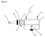
- FIG. 2 shows a similar structure as FIG. 1 with the difference that the optical pulse shaper 10 is not provided as an independent module.
- the transmission peak of the Fabry-Perot filter 6 is shifted periodically outside the bandpass filter 4, without a higher-order transmission appearing, whereby the Fabry-Perot filter 6 in combination with the band-pass filter 4, the function of the optical pulse shaper 10 is modeled.
- the Fabry-Perot filter 6 can fulfill a dual function, namely the spectral selection of individual wavelength ranges and additionally the function of the optical pulse shaper 10 and the mechanical chopper can be dispensed with.
- FIG. 3 shows an example of a possible measurement configuration for the components N2O, CO, NO, NO2, CO2, H2O, ie the absorption spectra of these components in a common image.
- the individual absorption spectra which are represented by thin lines, are scaled arbitrarily.
- the absorption bands shown are among the components mentioned, the bands also partially overlapping.
- the bold lines and reference symbols A to H and A ' represent the spectral positions of the likewise idealized Fabry-Perot filter transmission peaks used for the measurement the components are meaningful.
- Position A is a dark position.
- Position D is above a CO absorption, position F above a NO absorption, etc.
- a possible measurement strategy would be as follows: The positions B to H are successively set, for example at a temporal second distance or grid, and thus the appropriate wavelengths are selected to measure the individual components.
- the necessary for the measurement pulse shaping is done by approaching the position A or A 'in temporal millisecond distance or grid, whereby optical pulses are generated and the measurement can be carried out according to the principle described above.
- FIG. 4 shows a further embodiment with the light source 2 and downstream optics 22 for beam shaping.
- the bandpass filter 4 is arranged.
- the light filtered by the bandpass filter 4 continues to pass through the Fabry-Perot filter 6, which again serves to transmit an adjustable wavelength.
- the light filtered by the Fabry-Perot filter 6 then impinges on a dichroic beam splitter 8, which splits the light beam into two different wavelengths.
- a first light beam penetrating the dichroic beam splitter 8 is modulated by an optical pulse shaper 10 (chopper) before this light beam then enters the photoacoustic measuring cell 12.
- an optical pulse shaper 10 chopper
- the second light beam which is reflected by the dichroic beam splitter 8, also passes into the photoacoustic measuring cell 12 via three deflecting means 18 which deflect the light beam by 90 degrees.
- the deflecting means 18 can be designed, for example, as a deflecting mirror 19 or as a deflecting prism.
- the two frequency spectra, or wavelength spectra of the different orders are separated, for example from 2.9 ⁇ m to 4.2 ⁇ m for a shorter wavelength and from 4.4 ⁇ m to 7.7 ⁇ m for a longer wavelength optical path.
- a bandpass filter 4 may also be required here.
- an (other) optical pulse shaper 10 is provided, which is again designed as a chopper but now has different number of slots on two different radii. So z. B. the longer wavelength part with, for example, 1 kHz and the shorter wavelength part are larger than 2 kHz modulated.
- the signal evaluation is done with an evaluation unit as already to the FIGS. 1 and 2 described by the vibrating beam 24 and the interferometer 20 by means of a lock-in technique.
- the spectral ratios are shown, namely the qualitative absorption spectra, for a measurement with a device according to FIG. 4 , unlike FIG. 4 two bandpasses BP1 and BP2 are used.
- the two bandpass filters BP1 and BP2 are selected such that not several orders appear in the individual bandpass filters.
- the individual absorption spectra of the different gases are provided with offsets.
- the components CO, NO, NO2, SO2, CO2 and H2O are measured at a lock-in frequency f1 and in the short-wave range many hydrocarbons, for example CH4 here, as well as HCl at a lock-in frequency f2 become.
- the zero point signal is measured because at this wavelength absorptions are negligible.
- each partial light beam of the dichroic beam splitter 8 is influenced by a respective Fabry-Perot filter 6 or 7. This arrangement is useful if the spectral ranges can not be separated optimally.
- FIG. 6 shows the light source 2 and the downstream optics 22 for beam shaping.
- the bandpass filter 4 is arranged.
- the light filtered by the bandpass filter 4 continues to strike the dichroic beam splitter 8, which splits the light beam into two partial beams, each with different wavelength ranges.
- the partial light beam transmitted through the dichroic beam splitter 8 strikes the first Fabry-Perot filter 6, which serves to transmit an adjustable wavelength.
- the transmitted partial light beam is also modulated by the first Fabry-Perot filter 6 as an optical pulse shaper 10 before this partial light beam enters the photoacoustic measuring cell 12.
- the second partial light beam which is reflected by the dichroic beam splitter passes through three deflection means 18, which deflect the light beam in each case by 90 degrees, on the second Fabry-Perot filter 7, which adjusts a second wavelength.
- the reflected and deflected partial light beam, which penetrates the second Fabry-Perot filter 7, is also modulated by the second Fabry-Perot filter 7 as an optical pulse shaper 10, before this partial light beam then likewise enters the single photoacoustic measuring cell 12.
- the deflection means 18 may be formed, for example, as a deflection mirror 19 or as a deflection prism.
- a single photoacoustic measuring cell 12 is used.
- Next is dispensed with an additional mechanical optical pulse shaper, so a chopper.
- the individual spectral positions are adjusted stepwise or continuously by the two provided Fabry-Perot filters 6 and 7, respectively, and additionally shifted at different frequencies outside the spectral range of the associated bandpass filter 4 in order to simultaneously realize a wavelength selection as well as the function of the optical pulse shaper.
- a bandpass filter 4 between the beam splitter 8 and the light source 2 may also be required here
- the signal evaluation or signal separation also takes place in this embodiment by means of the vibrating beam 24, the photoacoustic measuring cell 12 and the interferometer 20 as already described.
- FIG. 7 is exemplified, in which configuration which gas components with the device FIG. 6 can be measured.
- the gas components NH3, CO2, S02, H2O can be measured, for example, with one of the Fabry-Perot filters in a long-wave range FP1, and N2O, CO, NO, NO2, CO2 and H2O in a short-wave range FP2.
- a wavelength range FP3 can be measured the components HF and HCl.
- Other combinations are also contemplated which are included in this invention. It is important that the free spectral range of the individual Fabry-Perot filters is greater than the spectral range to be scanned.
- the bandpass filters are illustrated in the exemplary embodiments idealized with passbands BP1, BP2 and BP3. These are adjusted so that only one order is detected. These are adapted to the actual achievable reflection or transmission properties of the Fabry-Perot mirrors.
Landscapes
- Physics & Mathematics (AREA)
- Health & Medical Sciences (AREA)
- Life Sciences & Earth Sciences (AREA)
- Chemical & Material Sciences (AREA)
- Analytical Chemistry (AREA)
- Biochemistry (AREA)
- General Health & Medical Sciences (AREA)
- General Physics & Mathematics (AREA)
- Immunology (AREA)
- Pathology (AREA)
- Spectroscopy & Molecular Physics (AREA)
- Investigating Or Analysing Materials By Optical Means (AREA)
Description
- Die Erfindung betrifft ein Gasmessgerät nach dem Oberbegriff von Anspruch 1.
- Aus der
DE 10 2005 049 522 B3 ist eine Gassensoranordnung bekannt mit einer Strahlungsvorrichtung, einem Gasmessraum, einer Detektorvorrichtung und einer Auswertevorrichtung, wobei die Auswertevorrichtung die Strahlungsvorrichtung steuert, die Detektorsignale aufzeichnet und auswertet und die Messgaskonzentration abhängig vom Ausgangssignal der Detektorvorrichtung bestimmt. Die Strahlungsvorrichtung weist mindestens zwei Messstrahlungsquellen und mindestens eine Referenzstrahlungsquelle auf, welche jeweils die Strahlung in mindestens einem Absorptionsband des zu detektierenden Gases, dem Messband, sowie die Strahlung in mindestens einem durch das Messgas nicht absorbierenden spektralen Band, dem Referenzband, ausstrahlen. Die Detektorvorrichtung ist so aufgebaut, dass sie die Strahlung nach deren Durchgang durch den Gasmessraum in einem Mess- bzw. in einem Referenzband jeweils räumlich und/oder zeitlich getrennt unabhängig empfangen kann, wobei die Auswertevorrichtung die Strahlungsquellen nach einem bestimmten Steuerungsalgorithmus betreibt und die Ausgangssignale der Detektorvorrichtung im Mess- und/oder im Referenzband beim Einschalten einer der Strahlungsquellen oder beim Strahlungsquellenvergleich feststellt und vergleicht, eine eventuelle Halterung der Gassensoranordnung gegebenenfalls kompensiert und die Messgaskonzentration bestimmt. - Bekannte Infrarotgassensoren weisen beispielsweise eine breitbandige Strahlungsquelle, eine Absorptionsstrecke bzw. einen Gasmessraum, ein wellenlängenselektivierendes Element, z. B. ein optisches Bandpassfilter, wie ein Interferenzfilter, ein Fabry-Perot-Interferometer oder ein Gitter und einen Strahlungsdetektor, beispielsweise einen pyroelektrischen Detektor, einen Halbleiterdetektor oder einen thermophilen Detektor auf. Die Abschwächung der am Detektor ankommenden Strahlung aufgrund der Absorption durch die Gasmoleküle ist ein Maß für die Konzentration des bei der eingestellten Wellenlänge absorbierenden Gases. Das Wellenlängen selektierende Element kann vor und/oder hinter dem Gasmessraum angeordnet werden.
- Der Einsatz einer wellenlängenselektiven Strahlungsquelle wie z. B. einer LED oder eines Lasers in Kombination mit nichtwellenlängenselektiven Strahlungsempfängern ist ebenfalls bekannt.
- Die Strahlungsabsorption durch Gasmoleküle im Infrarotbereich wird auch in photoakustischen Gassensoren benutzt. Die Strahlungsabsorption führt zur Erwärmung des Gases im Gasmessraum. Die daraus resultierende Druckänderung wird mittels eines akustischen Detektors wie z.B. eines Mikrofons oder mittels eines Drucksensors registriert.
- Die
US 2004/0145741A1 offenbart eine Gasmesszelle mit einem ersten Filter und einem zweiten Filter, welches als Fabry-Perot-Filter ausgebildet ist. Das zweite Filter kann über einen Modulator beeinflusst werden, so dass die Wellenlänge und eine Lichtintensität einstellbar list. - Eine Veröffentlichung von Koskinen et al. mit dem Titel 'Cantilever enhanced photoacoustic detection of carbon dioxide using a tunable diode laser source' Appl. Phys. B86, Seiten 451-454, 2007; offenbart eine photoakustische Messzelle.
- Die
US 4 457 162 offenbart eine photoakustische Messzelle mit einem Bandfilter und einem Chopper. - Eine Veröffentlichung von Uotila mit dem Titel 'Comparison of infrared sources for a differential photoacoustic gas detection system' Infrared Physics & Technology, Band 51, Seiten 122-130, 2007, offenbart eine photoakustische Messzelle.
- Die
WO 2007/054751A1 offenbart ebenfalls eine photoakustische Messzelle. - Aufgabe der vorliegenden Erfindung ist es, ein Gasmessgerät bereitzustellen, welches idealerweise ohne makroskopisch mechanisch bewegliche Teile auskommt und die zu untersuchende Wellenlänge bzw. das zu untersuchende Frequenzspektrum kontinuierlich veränderbar ist. Weiter soll eine Messgeschwindigkeit erhöht werden. Eine weitere Aufgabe besteht darin ein Gasmessgerät zur Verfügung zu stellen, das geeignet ist, Konzentrationen einer Vielzahl von Messgasen zu bestimmen ohne dass Teile, wie Filter mechanisch ausgetauscht werden müssen.
- Die Aufgabe wird gelöst durch ein Gasmessgerät gemäß Anspruch 1.
- Da das Gasmessgerät nach der Erfindung nahezu ohne makroskopisch mechanisch bewegte Teile auskommt, ist diese wenig störanfällig. Mechanisch bewegte Teile sind durch Reibung einem Verschleiß unterworfen, der dazu führt, dass das Gasmessgerät gewartet werden muss. Durch die fehlenden mechanisch bewegten Teile ist das Gasmessgerät robuster und preiswerter ausgebildet.
- Das Fabry-Perot-Filter besteht aus einem optischen Resonator, der aus zwei teildurchlässigen Spiegeln gebildet wird. Ein eintreffender Lichtstrahl wird nur dann durch das
- Fabry-Perot-Filter transmittiert, wenn er dessen Resonanzbedingungen entspricht. Andere Spektralbereiche werden nahezu vollständig ausgelöscht. Dies geschieht durch konstruktive bzw. destruktive Interferenz der Teilstrahlen. Das Fabry-Perot-Filter wirkt dadurch als optisches Filter. Durch mikromechanische Verschiebung der Spiegel kann die Wellenlänge verändert werden, welche durch das Fabry-Perot-Filter hindurch treten soll.
- Durch die Verwendung des Fabry-Perot-Filters kann die transmittierte Wellenlänge des Lichtstrahles veränderlich eingestellt werden, so dass die photoakustische Messzelle mit Licht veränderlicher Wellenlänge beaufschlagbar ist, wodurch unterschiedliche Absorptionsspektren von unterschiedlichen Gasen eines Gasgemisches nacheinander eingestellt werden können. Die spektralen Wellenlängen, bei denen die verschiedenen Gase eine Absorption aufweisen, können gemäß der Erfindung auch kontinuierlich durchgestimmt werden.
- Die veränderlichen Wellenlängen des Lichtstrahles können durch das Fabry-Perot-Filter sehr schnell, nämlich im Bereich von wenigen Sekunden, insbesondere im Bereich von wenigen Millisekunden eingestellt werden.
- Das Fabry-Perot-Filter ist beispielsweise als piezogesteuertes Fabry-Perot-Filter ausgebildet. Das Fabry-Perot-Filter ist dabei als Mikro-Elektro-Mechanisches-System aufgebaut. Solche Systeme sind auch unter der Abkürzung MEMS bekannt. Das erfindungsgemäß eingesetzte Fabry-Perot-Filter kann beispielsweise elektrostatisch oder piezoelektrisch angesteuert werden.
- Das Breitbandfilter ist notwendig, um höhere Ordnungen der Wellenlängen auszublenden. Somit ist es möglich, die Messung nur für eine einzige, nämlich die erste Ordnung eines Absorptionsspektrums zu begrenzen, wodurch eine präzise und genaue Bestimmung des zu messenden Gases ermöglicht wird.
- In Weiterbildung der Erfindung ist nur eine einzige Lichtquelle vorgesehen. Dadurch ist das Gasmessgerät günstiger herstellbar.
- In Weiterbildung weist die photoakustische Messzelle einen Schwingbalken und ein Interferometer zur Messung der Auslenkung des Schwingbalkens auf. Durch die Absorption der Lichtstrahlen durch das Gas bei einem bestimmten Absorptionsspektrum wird das Gas in einem sehr kurzen Zeitraum erwärmt, wodurch eine impulsartige Druckänderung des Gases in der photoakustischen Messzelle erfolgt. Diese Druckänderung führt zu einer Auslenkung des Schwingbalkens. Der Schwingbalken, welcher auch als Cantilever bezeichnet wird, besteht beispielsweise aus einer Siliziummembran. Der Schwingbalken dient als optisches Element für ein Interferometer. Mit Hilfe des Interferometers kann eine Auslenkung des Schwingbalkens auf Basis der Interferenzmessung sehr präzise bestimmt werden.
- Gemäß einer weiteren bevorzugten Ausführungsform ist zwischen der Lichtquelle und der photoakustischen Messzelle ein optischer Pulsformer vorgesehen. Durch den optischen Pulsformer wird das Licht der Lichtquelle moduliert. Besonders bevorzugt wird durch den optischen Pulsformer pulsiertes Licht erzeugt, wodurch die Absorption in dem Messgas zyklisch erfolgt, wodurch ein Schwingverhalten des Schwingbalkens verbessert wird, insbesondere wenn ein Resonanzverhalten durch den Pulsformer erreicht wird. Der optische Pulsformer wird im einfachsten Fall durch eine drehbare Schlitz- oder Lochblende verwirklicht, wodurch eine zyklische Unterbrechung des Lichtstrahles erreicht wird. Derartige optische Pulsformer werden auch als Chopper bezeichnet.
- Besonders bevorzugt bildet jedoch das Fabry-Perot-Filter selbst den optischen Pulsformer. D. h. das Fabry-Perot-Filter wird zum einem wie bereits erwähnt so eingestellt, dass nur eine bestimmte Wellenlänge des Lichtes hindurch treten kann. Weiter wird das Fabry-Perot-Filter derart zyklisch angesteuert, dass das Licht nur zu bestimmten Zeiten im Zyklus das Fabry-Perot-Filter durchdringen kann, wodurch pulsförmiges Licht am Ausgang des Fabry-Perot-Filters entsteht. Dadurch kommt dem Fabry-Perot-Filter erfindungsgemäß eine Doppelfunktion zu, wodurch die Vorrichtung deutlich vereinfacht wird. Das Fabry-Perot-Filter wird über eine Steuereinheit angesteuert, mit der eine gewünschte transmittierte Wellenlänge des Fabry-Perot-Filters und die Frequenz sowie das Puls-Pausenverhältnis, mit der das Licht durch das Fabry-Perot-Filter unterbrochen wird, eingestellt wird.
- In Weiterbildung der Erfindung ist zwischen der Lichtquelle und der photoakustischen Messzelle ein dichroitischer Strahlteiler angeordnet, wobei ein erster Lichtanteil, welcher den Strahlteiler durchdringt, direkt in die photoakustische Messzelle fällt und der vom Strahlteiler reflektierte Lichtanteil über Umlenkmittel in die photoakustische Messzelle geführt ist. Vor dem Strahlteiler ist das Fabry-Perot-Filter angeordnet, um eine gewünschte Wellenlänge zu selektieren, bzw. um das Licht in der Intensität zu modulieren. Durch die vorgenannte Weiterbildung ist es möglich, mehrere Spektralkomponenten zu messen, obwohl der dazu notwendige Spektralbereich so groß ist, dass der freie spektrale Bereich des Fabry-Perot-Filters zunächst nicht ausreicht. Durch den dichroitischen Strahlteiler werden jedoch nun mehrere Ordnungen, beispielsweise die erste und zweite oder die erste und dritte Ordnung des einzigen Fabry-Perot-Filters ausgenutzt und über den Strahlteiler und mittels Umlenkmitteln, welche als Umlenkspiegel oder Umlenkprismen ausgeführt sein können, der einzigen photoaktustischen Messzelle zugeführt. Zur Modulation der Lichtstrahlen nach dem dichroitischen Strahlteiler ist jeweils ein optischer Pulsformer angeordnet. Der optische Pulsformer kann beispielsweise auch durch ein Chopper realisiert werden, wobei der Chopper eine unterschiedliche Schlitzanzahl auf zwei verschiedenen Radien für die unterschiedlichen Lichtstrahlen aufweist.
- In einer weiteren besonderen Ausführungsform ist zwischen einem Umlenkmittel und der photoakustischen Messzelle ein zweites Fabry-Perot-Filter angeordnet. Dadurch ist es nun möglich, dass jeder Lichtstrahl des dichroitischen Strahlteilers von je einem Fabry-Perot-Filter beeinflussbar ist. In jedem der beiden Lichtstrahlen kann die exakte Wellenlänge durch das jeweilige Fabry-Perot-Filter eingestellt werden, und zusätzlich kann die Lichtmodulation für jeden Lichtstrahl unabhängig voneinander durch das jeweilige Fabry-Perot-Filter eingestellt werden. Gemäß dieser Weiterbildung entfällt ein zusätzlicher optischer Pulsformer, da das jeweilige Fabry-Perot-Filter die Funktion des optischen Pulsformers übernimmt.
- Die Erfindung wird nachstehend auch hinsichtlich weiterer Vorteile und Merkmale unter Bezugnahme auf die beigefügte Zeichnung anhand von Ausführungsbeispielen erläutert. Die Figuren der Zeichnung zeigen in:
- Figur 1
- ein Gasmessgerät gemäß einem ersten Ausführungsbeispiel;
- Figur 2
- ein Gasmessgerät gemäß einem zweiten Ausführungsbeispiel;
- Figur 3
- eine beispielhafte Messkonfiguration für verschiedene Messgase;
- Figur 4
- ein Gasmessgerät gemäß einem dritten Ausführungsbeispiel;
- Figur 5
- eine qualitative Darstellung von Absorptionsspektren gemäß einem weiteren Ausführungsbeispiel;
- Figur 6
- ein Gasmessgerät gemäß einem vierten Ausführungsbeispiel;
- Figur 7
- eine qualitative Darstellung von Absorptionsspektren gemäß einem weiteren Ausführungsbeispiel.
- In den nachfolgenden Figuren sind verschiedene Ausführungsbeispiele dargestellt, in denen identische Teile mit identischen Bezugszeichen versehen sind. Merkmale der unterschiedlichen Ausführungsbeispiele sind miteinander kombinierbar.
-
Figur 1 zeigt ein Gasmessgerät 1 zur Messung der Konzentration mehrerer Gaskomponenten mittels Absorptionsmessung mit einer Lichtquelle 2 für infrarote Strahlung (thermischen Strahler). Weiter ist eine Optik 22 zur Bündelung des Lichts der Lichtquelle 2, ein Bandpassfilter 4 und eine photoakustische Messzelle 12 zur Messung der Gaskonzentrationen mehrerer Komponenten vorgesehen. Zur Selektion einer Wellenlänge, um ein Absorptionsspektrum aufzunehmen, ist zusätzlich zum Bandpassfilter und bevorzugt zwischen dem Bandpassfilter 4 und der photoakustischen Messzelle 12 ein Fabry-Perot-Filter 6 vorgesehen. Die photoakustische Messzelle 12 weist einen Gaseinlass 14 und einen Gasauslass 16 auf. - Dabei sendet die Lichtquelle 2 infrarotes Licht aus (thermischer Strahler). Die photoakustische Messzelle 12 ist mit einem zu untersuchenden Gas befüllt. Nur wenn Gase im Messvolumen vorhanden sind, die bei den ausgewählten spektralen Wellenlängen absorbieren, wird infrarote Strahlung absorbiert. Dies führt zu einer Erwärmung und damit zu einer Druckerhöhung in der Messzelle. Diese Druckerhöhung führt zu einer Auslenkung eines Schwingbalkens 24, welcher als Membran, insbesondere als Siliziummembran ausgebildet ist. Eine solche Membran wird wie bereits erwähnt auch als Cantilever bezeichnet. Die Auslenkung der Membran wird wiederum durch ein Interferometer 20 sehr genau bestimmt, wobei die Auslenkung proportional zur Konzentration des Messgases im Messvolumen der photoakustischen Messzelle 12 ist.
- Mit Hilfe eines Fabry-Perot-Filters 6, insbesondere eines piezogesteuerten Fabry-Perot-Filters 6 oder eines Fabry-Perot-Filters 6 in mikromechanischer Bauweise, welches elektrostatisch oder piezoelektrisch angesteuert wird, werden die spektralen Positionen der Gaskomponenten ohne makroskopisch bewegte mechanische Komponenten eingestellt und ggf. auch kontinuierlich durchgestimmt. Die Veränderung und Einstellung der spektralen Wellenlängen erfolgt in Sekunden bis wenigen Millisekunden. Um Interferenzen höherer Ordnungen auszublenden, ist ein Bandpassfilter 4 vorgesehen. Gemäß dem ersten Ausführungsbeispiel gemäß
Figur 1 können Wellenlängen von 4,3 µm bis 7,4 µm eingestellt werden, um die Gaskomponenten CO, NO, S02, NO2, N2O, CO2 und H2O mittels nur einem einzigen Fabry-Perot-Filter 6 zu messen. Beispielsweise können mit dem Aufbau gemäßFigur 1 im Wellenlängenbereich von 3 µm bis 3,8 µm viele verschiedene Kohlenwasserstoffe gemessen werden. Gemäß diesem Ausführungsbeispiel können alle Gaskomponenten gemessen werden, deren Absorptionsbanden sich innerhalb des eingestellten freien spektralen Bereichs des Fabry-Perot-Filters 6 befinden. Das zusätzliche Messen und Hinzufügen weiterer Gaskomponenten ist sehr einfach möglich, wenn diese innerhalb des Fabry-Perot-Filters 6 Absorptionsbanden aufweisen. - Die Intensität des Lichts wird in diesem Ausführungsbeispiel mit einem optischen Pulsformer 10, insbesondere einer drehbaren Schlitzscheibe, auch Chopper genannt, moduliert. Dann wird das Gas in der photoakustischen Messzelle 12 entsprechend der Modulation absorbieren, was zur periodischen Auslenkung des Schwingbalkens 24 führt. Die Schwingung des Schwingbalkens 24 wird über das Interferometer 20 bestimmt, wobei die Auslenkung, wie oben beschrieben, ein Maß für die Konzentration ist.
-
Figur 2 zeigt einen ähnlichen Aufbau wieFigur 1 mit dem Unterschied, dass der optische Pulsformer 10 nicht als eigenständige Baugruppe vorgesehen ist. In diesem Fall wird die Transmissionsspitze des Fabry-Perot-Filters 6 periodisch außerhalb des Bandpassfilters 4 verschoben, ohne dass eine Transmission für eine höhere Ordnung erscheint, womit durch das Fabry-Perot-Filter 6 in Kombination mit dem Bandpassfilter 4 die Funktion des optischen Pulsformers 10 nachgebildet ist. Dadurch kann erfindungsgemäß das Fabry-Perot-Filter 6 eine Doppelfunktion erfüllen, nämlich die spektrale Selektion einzelner Wellenlängenbereiche und zusätzlich die Funktion des optischen Pulsformers 10 und es kann der mechanische Chopper entfallen. -
Figur 3 zeigt exemplarisch eine mögliche Messkonfiguration für die Komponenten N2O, CO, NO, NO2, CO2, H2O, also die Absorptionsspektren dieser Komponenten in einem gemeinsamen Bild. Die einzelnen Absorptionsspektren, die durch dünne Striche dargestellt sind, sind beliebig skaliert. Die dargestellten Absorptionsbanden gehören zu den genannten Komponenten, wobei die Banden sich teilweise auch überlappen. Mit fetten Linien und Bezugszeichen A bis H und A' sind die Spektralpositionen der ebenfalls idealisierten Fabry-Perot-Filter-Transmissionsspitzen dargestellt, die zur Messung der Komponenten sinnvoll sind. Position A ist eine Dunkelstellung. Position D liegt über einer CO Absorption, Position F über einer NO Absorption usw. Eine mögliche Messstrategie wäre wie folgt: Es werden nacheinander, beispielsweise in einem zeitlichen Sekundenabstand, bzw. -raster die Positionen B bis H eingestellt und damit die jeweils passende Wellenlängen selektiert, um die einzelnen Komponenten zu vermessen. Die zur Messung notwendige Pulsformung erfolgt durch Anfahren der Position A oder A' im zeitlichen Millisekundenabstand bzw. -raster, wodurch optische Pulse erzeugt werden und die Messung nach dem oben beschriebenen Prinzip erfolgen kann. -
Figur 4 zeigt ein weiteres Ausführungsbeispiel mit der Lichtquelle 2 und nachgeordneter Optik 22 zur Strahlformung. Nach der Optik 22 ist das Bandpassfilter 4 angeordnet. Das durch das Bandpassfilter 4 gefilterte Licht durchdringt weiter das Fabry-Perot-Filter 6, welches hier wieder dazu dient, eine einstellbare Wellenlänge zu transmittieren. Das durch das Fabry-Perot-Filter 6 gefilterte Licht trifft dann auf einen dichroitischen Strahlteiler 8, welcher den Lichtstrahl in zwei unterschiedlichen Wellenlängen aufteilt. Ein erster, den dichroitischen Strahlteiler 8 durchdringender Lichtstrahl wird von einem optischen Pulsformer 10 (Chopper) moduliert, bevor dieser Lichtstrahl dann in die photoakustische Messzelle 12 gelangt. Der zweite Lichtstrahl, der von dem dichroitischen Strahlteiler 8 reflektiert wird, gelangt über drei Umlenkmittel 18, welche den Lichtstrahl jeweils um 90 Grad umlenken, ebenfalls in die photoakustische Messzelle 12. Die Umlenkmittel 18 können beispielsweise als Umlenkspiegel 19 oder als Umlenkprisma ausgebildet sein. - Durch die vorgenannte Weiterbildung gemäß
Figur 4 ist es möglich mehrere Spektralkomponenten zu messen, obwohl der dazu notwendige Spektralbereich so groß ist, dass der freie spektrale Bereich des Fabry-Perot-Filters 6 eigentlich nicht ausreicht. Durch den dichroitischen Strahlteiler 8 werden jetzt mehrere Ordnungen, beispielsweise die erste und zweite oder die erste und dritte Ordnung des Fabry-Perot-Filters 6 ausgenutzt. Damit die Messung mit nur einer einzigen photoakustischen Messzelle 12 durchgeführt werden kann, ist der Aufbau gemäßFigur 4 vorgesehen. Mit Hilfe des dichroitischen Strahlteilers 8 werden die beiden Frequenzspektren, bzw. Wellenlängenspektren der unterschiedlichen Ordnungen separiert, beispielsweise von 2,9µm bis 4.2µm für einen kurzwelligeren und von 4,4µm bis 7,7µm für einen langwelligeren optischen Pfad. Abhängig von der Güte des dichroitischen Strahlteilers 8 kann auch hier noch ein Bandpassfilter 4 erforderlich sein. - Um die beiden Spektralbereiche auf den beiden optischen Wegen auch messtechnisch mit dem einzigen Nächweisgerät (Messzelle 12) trennen zu können, ist ein (anderer) optischer Pulsformer 10 vorgesehen, der wieder als Chopper ausgebildet ist, aber jetzt unterschiedliche Schlitzanzahl auf zwei unterschiedlichen Radien aufweist. So kann z. B. der langwelligere Teil mit beispielsweise 1 kHz und der kurzwelligere Teil mit größer 2 kHz moduliert werden. Das Fabry-Perot-Filter 6 kann beispielsweise neben den genannten Ausführungen, auch kontinuierlich durchgestimmt werden. Die Signalauswertung erfolgt mit einer Auswerteeinheit wie bereits zu den
Figuren 1 und2 beschrieben durch den Schwingbalken 24 und das Interferometer 20 mittels einer Lock-In Technik. - In
Figur 5 sind die spektralen Verhältnisse dargestellt, nämlich die qualitativen Absorptionsspektren, für eine Messung mit einer Vorrichtung gemäßFigur 4 , wobei im Unterschied zuFigur 4 zwei Bandpässe BP1 und BP2 eingesetzt werden. Die beiden Bandpässe BP1 und BP2 sind so gewählt, dass nicht mehrere Ordnungen in den einzelnen Bandpassfiltern erscheinen. Zur besseren Übersicht sind die einzelnen Absorptionsspektren der verschiedenen Gase mit Offsets versehen. In dieser Konfiguration können im langwelligen Bereich die Komponenten CO, NO, NO2, S02, CO2 sowie H2O bei einer Lock-In Frequenz f1 und im kurzwelligen Bereich viele Kohlenwasserstoffe, beispielhaft ist hier CH4 gezeigt, sowie HCl bei einer Lock-In Frequenz f2 gemessen werden. Bei etwa 4µm wird das Nullpunktsignal gemessen, da bei dieser Wellenlänge Absorptionen vernachlässigbar sind. - Im unteren Grafikbereich sind einige Transmissionskurven des Fabry-Perot-Filters 6 für verschiedene Abstände der Spiegel des Fabry-Perot-Filters gezeigt. Insbesondere wenn die HO-Absorption bei der modulierten Infraratstrahlung zu groß wird, kann auch zwischen 1800 nm und 2200 nm sowohl H2O also Wasser als auch CO2 gemessen werde, indem hierfür die dritte Ordnung verwendet wird.
- In einer weiteren Ausführungsform gemäß
Figur 6 ist zwischen einem Umlenkmittel 18 bzw. einem Umlenkspiegel 19 und der photoakustischen Messzelle 12 ein zweites Fabry-Perot-Filter 7 angeordnet. Dadurch ist es nun möglich, dass jeder Teillichtstrahl des dichroitischen Strahlteilers 8 von je einem Fabry-Perot-Filter 6 bzw. 7 beeinflussbar ist. Diese Anordnung ist dann sinnvoll, wenn die Spektralbereiche nicht optimal separiert werden können. -
Figur 6 zeigt die Lichtquelle 2 und die nachgeordnete Optik 22 zur Strahlformung. Nach der Optik 22 ist der Bandpassfilter 4 angeordnet. Das durch das Bandpassfilter 4 gefilterte Licht trifft weiter auf den dichroitischen Strahlteiler 8, welcher den Lichtstrahl in zwei Teilstrahlen mit jeweils unterschiedlichen Wellenlängenbereichen aufteilt. Der durch den dichroitischen Strahlteiler 8 transmittierte Teillichtstrahl trifft auf das erstes Fabry-Perot-Filter 6, welches dazu dient, eine einstellbare Wellenlänge zu transmittieren. Der transmittierte Teillichtstrahl wird durch das erste Fabry-Perot-Filter 6 als optischer Pulsformer 10 auch moduliert, bevor dieser Teillichtstrahl in die photoakustische Messzelle 12 gelangt. Der zweite Teillichtstrahl, der von dem dichroitischen Strahlteiler reflektiert wird, gelangt über drei Umlenkmittel 18, die den Lichtstrahl jeweils um 90 Grad umlenken, auf das zweite Fabry-Perot-Filter 7, welches eine zweite Wellenlänge einstellt. Der reflektierte und umgelenkte Teillichtstrahl, welcher das zweite Fabry-Perot-Filter 7 durchdringt, wird von dem zweiten Fabry-Perot-Filter 7 als optischer Pulsformer 10 ebenfalls moduliert, bevor dieser Teillichtstrahl dann ebenfalls in die einzige photoakustische Messzelle 12 gelangt. Die Umlenkmittel 18 können beispielsweise als Umlenkspiegel 19 oder als Umlenkprisma ausgebildet sein. - Es wird wiederum nur eine einzige photoakustische Messzelle 12 verwendet. Weiter wird auf einen zusätzlichen mechanischen optischen Pulsformer, also einen Chopper verzichtet. Durch die beiden vorgesehenen Fabry-Perot-Filter 6 bzw. 7 werden schrittweise oder kontinuierlich die einzelnen Spektralpositionen eingestellt und zusätzlich mit unterschiedlichen Frequenzen außerhalb des Spektralbereichs des zugeordneten Bandpassfilters 4 verschoben, um auch hier gleichzeitig eine Wellenlängenselektion sowie die Funktion des optischen Pulsformers zu realisieren. Abhängig von der Güte des dichroitischen Strahlteilers 8 kann auch hier noch ein Bandpassfilter 4 zwischen dem Strahlteiler 8 und der Lichtquelle 2 erforderlich sein
- Die Signalauswertung bzw. Signaltrennung erfolgt auch in diesem Ausführungsbeispiel mittels des Schwingbalkens 24, der photoakustischen Messzelle 12 und dem Interferometer 20 wie bereits beschrieben.
- In
Figur 7 ist beispielhaft dargestellt, in welcher Konfiguration welche Gaskomponenten mit der Vorrichtung ausFigur 6 gemessen werden können. Zur besseren Übersicht sind die einzelnen Absorptionsspektren der Gase mit Offsets versehen. Die Gaskomponenten NH3, CO2, S02, H2O können beispielsweise mit einem der Fabry-Perot-Filter in einem langwelligen Bereich FP1, sowie N2O, CO, NO, NO2, CO2 und H2O in einem kurzwelligen Bereich FP2 gemessen werden. In einem Wellenlängenbereich FP3 können die Komponenten HF und HCl gemessen werden. Es sind auch andere Kombinationen vorgesehen, die in dieser Erfindung mit umfasst sind. Wichtig ist, dass der freie Spektralbereich der einzelnen Fabry-Perot-Filter größer als der abzutastende spektrale Bereich ist. Die Bandpassfilter sind in den Ausführungsbeispielen idealisiert mit Durchlassbereichen BP1, BP2 und BP3 dargestellt. Diese werden so eingestellt, dass immer nur eine Ordnung detektiert wird. Diese werden an die tatsächlichen erreichbaren Reflexions- bzw. Transmissionseigenschaften der Fabry-Perot-Spiegel angepasst. -
- 1 Gasmessgerät
- 2 Lichtquelle für infrarote Strahlung
- 4, BP1, BP2, BP3 Bandpassfilter
- BP1, BP2, BP3, Durchlassbereiche der Bandpassfilter
- 6, Fabry-Perot-Filter
- 7, zweites Fabry-Perot-Filter
- FP1, FP2, FP3, Wellenlängenbereiche der Fabry-Perot-Filter
- 8 dichroitischer Strahlteiler
- 10 optischer Pulsformer
- 12 Photoakustische Messzelle
- 14 Gaseinlass
- 16 Gasauslass
- 18 Umlenkmittel
- 19 Umlenkspiegel
- 20 Interferometer
- 22 Optik
- 24 Schwingbalken
- A Position Dunkelstellung zweite Ordnung
- A' Positon Dunkelstellung erste Ordnung
- B, C, D, E, F, G, H Spektralpositionen
Claims (4)
- Gasmessgerät zur Messung der Konzentration mehrerer Gaskomponenten mittels Absorptionsmessung mit einer Lichtquelle (2) für infrarote Strahlung, einer Optik (22) zur Bündelung des Lichts der Lichtquelle (2), einem Bandpassfilter (4) und einer photoakustischen Messzelle (12) zur Messung von Gaskonzentrationen,
dadurch gekennzeichnet,
dass zur Selektion der Absorptionsspektren zusätzlich zu dem Bandpassfilter (4) zwischen dem Bandpassfilter (4) und der photoakustischen Messzelle (12) ein Fabry-Perot-Filter (6) vor der photoakustischen Messzelle (12) vorgesehen ist, wobei durch das Fabry-Perot-Filter (6) die transmittierte Wellenlänge des Lichtstrahles veränderlich einstellbar ist, so dass die photoakustische Messzelle (12) mit Licht veränderlicher Wellenlänge beaufschlagbar ist, wodurch unterschiedliche Absorptionsspektren von unterschiedlichen Gasen eines Gasgemisches nacheinander einstellbar sind und die spektralen Wellenlängen, bei denen die verschiedenen Gase eine Absorption aufweisen, kontinuierlich durchstimmbar sind, wobei die photoakustische Messzelle (12) ein Schwingbalken (24) und ein Interferometer (20) zur Messung der Auslenkung des Schwingbalkens (24) aufweist und zwischen der Lichtquelle (2) und der photoakustischen Messzelle (12) ein optischer Pulsformer (10) vorgesehen ist. - Gasmessgerät nach Anspruch 1, dadurch gekennzeichnet, dass der optische Pulsformer (10) durch das Fabry-Perot-Filter (6) gebildet ist.
- Gasmessgerät nach einem der vorhergehenden Ansprüche, dadurch gekennzeichnet, dass zwischen der Lichtquelle (2) und der photoakustischen Messzelle (12f) ein dichroitischer Strahlteiler (8) angeordnet ist, wobei ein erster Lichtanteil, welcher durch den Strahlteiler (8) fällt, direkt in die photoakustische Messzelle (12) fällt und der reflektierte Lichtanteil des Strahlteilers (8) über Umlenkmittel (18) in die photoakustische Messzelle (12) geführt ist.
- Gasmessgerät nach Anspruch 2, dadurch gekennzeichnet, dass zwischen einem Umlenkmittel (18) und der photoakustischen Messzelle (12) ein zweites Fabry-Perot-Filter (7) angeordnet ist.
Priority Applications (2)
| Application Number | Priority Date | Filing Date | Title |
|---|---|---|---|
| EP13156530.1A EP2770319B2 (de) | 2013-02-25 | 2013-02-25 | Gasmessgerät |
| US14/179,050 US9360417B2 (en) | 2013-02-25 | 2014-02-12 | Gas measurement device |
Applications Claiming Priority (1)
| Application Number | Priority Date | Filing Date | Title |
|---|---|---|---|
| EP13156530.1A EP2770319B2 (de) | 2013-02-25 | 2013-02-25 | Gasmessgerät |
Publications (3)
| Publication Number | Publication Date |
|---|---|
| EP2770319A1 EP2770319A1 (de) | 2014-08-27 |
| EP2770319B1 true EP2770319B1 (de) | 2016-02-03 |
| EP2770319B2 EP2770319B2 (de) | 2022-01-26 |
Family
ID=47757410
Family Applications (1)
| Application Number | Title | Priority Date | Filing Date |
|---|---|---|---|
| EP13156530.1A Active EP2770319B2 (de) | 2013-02-25 | 2013-02-25 | Gasmessgerät |
Country Status (2)
| Country | Link |
|---|---|
| US (1) | US9360417B2 (de) |
| EP (1) | EP2770319B2 (de) |
Cited By (1)
| Publication number | Priority date | Publication date | Assignee | Title |
|---|---|---|---|---|
| EP3919890A1 (de) | 2020-06-05 | 2021-12-08 | Hahn-Schickard-Gesellschaft für angewandte Forschung e.V. | Photoakustische spektroskopie an gasgemischen über abstimmbares fabry-pérot-interferometer |
Families Citing this family (9)
| Publication number | Priority date | Publication date | Assignee | Title |
|---|---|---|---|---|
| EP3012616A1 (de) * | 2014-10-22 | 2016-04-27 | Services Petroliers Schlumberger | System und Verfahren zur Analyse einer gasförmigen, aus einer Bohrflüssigkeit aus einem Bohrloch extrahierten Probe |
| DE102014226845B4 (de) * | 2014-12-17 | 2016-11-03 | Siemens Aktiengesellschaft | Absorptionsspektrometer |
| US10168239B2 (en) * | 2014-12-24 | 2019-01-01 | Intel Corporation | Gas sensing devices, systems, and associated methods |
| NO344002B1 (en) | 2015-09-29 | 2019-08-12 | Sintef Tto As | Optical gas detector |
| FR3078155B1 (fr) * | 2018-02-19 | 2020-08-14 | Commissariat Energie Atomique | Capteur photo-acoustique avec couplage opto-mecanique. |
| US11143626B2 (en) * | 2019-01-11 | 2021-10-12 | Infineon Technologies Ag | Photo-acoustic gas sensor with optimal reference path length |
| CN114486773B (zh) * | 2021-12-29 | 2024-08-30 | 聚光科技(杭州)股份有限公司 | 多种气体的分析装置和方法 |
| DE102022128472A1 (de) * | 2022-10-27 | 2024-05-02 | Fraunhofer-Gesellschaft zur Förderung der angewandten Forschung eingetragener Verein | Anordnung und Verfahren zur Bestimmung der Konzentration eines oder mehrerer Stoffe in einem flüssigen oder gasförmigen Medium |
| NO20221394A1 (en) | 2022-12-22 | 2024-06-24 | Tunable As | Improved noise canceling detector |
Citations (14)
| Publication number | Priority date | Publication date | Assignee | Title |
|---|---|---|---|---|
| US4457162A (en) | 1982-09-17 | 1984-07-03 | Institute Of Gas Technology | Multi-frequency photo-acoustic detector |
| US4525067A (en) | 1982-10-22 | 1985-06-25 | The United States Of America As Represented By The Secretary Of Commerce | Twin-etalon scanning spectrometer |
| EP0195685A2 (de) | 1985-03-21 | 1986-09-24 | Westinghouse Electric Corporation | Verfahren und Vorrichtung zum Nachweis und zur Messung von Gasen |
| DE3925692C1 (de) | 1989-08-03 | 1990-08-23 | Hartmann & Braun Ag, 6000 Frankfurt, De | |
| US5357340A (en) * | 1989-10-12 | 1994-10-18 | Hartmann & Braun | Method for spectroscopy using two Fabry-Perot interference filters |
| US20040145741A1 (en) | 2003-01-24 | 2004-07-29 | Honeywell International Inc. | Comb etalon fluid analyzer |
| WO2007054751A1 (en) | 2005-11-14 | 2007-05-18 | Szegedi Tudományegyetem | Method and apparatus for the selective photoacoustic detection of contaminants in a gaseous sample by making use of spectrally distant exciting wavelengths |
| DE102005049522B3 (de) | 2005-10-17 | 2007-06-06 | Gasbeetle Gmbh | Gassensoranordnung |
| CN201034939Y (zh) | 2007-04-13 | 2008-03-12 | 杭州远方光电信息有限公司 | 荧光粉激发测量装置 |
| EP1962077A1 (de) | 2007-02-21 | 2008-08-27 | IR Microsystems S.A. | Gassensor |
| EP1546684B1 (de) | 2002-09-30 | 2011-11-09 | Gasera Ltd | Fotoakustischer detektor |
| EP1546683B1 (de) | 2002-09-30 | 2011-11-16 | Gasera Ltd | Fotoakustischer detektor |
| US8330956B1 (en) | 2009-06-01 | 2012-12-11 | Stc.Unm | Optical coupled-cavity photo-acoustic spectroscopy |
| GB2492841A (en) | 2011-07-15 | 2013-01-16 | Secr Defence | Laser photoacoustic spectroscopy using a plurality of tuneable lasers |
Family Cites Families (4)
| Publication number | Priority date | Publication date | Assignee | Title |
|---|---|---|---|---|
| FI91564C (fi) * | 1991-10-31 | 1994-07-11 | Valtion Teknillinen | Anturi |
| US20030209669A1 (en) * | 2002-05-09 | 2003-11-13 | Chou Bruce C. S. | Miniaturized infrared gas analyzing apparatus |
| US8695402B2 (en) * | 2010-06-03 | 2014-04-15 | Honeywell International Inc. | Integrated IR source and acoustic detector for photoacoustic gas sensor |
| EP2857811B1 (de) * | 2013-10-02 | 2015-09-23 | Sick Ag | Spektrometer zur Gasanalyse |
-
2013
- 2013-02-25 EP EP13156530.1A patent/EP2770319B2/de active Active
-
2014
- 2014-02-12 US US14/179,050 patent/US9360417B2/en active Active
Patent Citations (14)
| Publication number | Priority date | Publication date | Assignee | Title |
|---|---|---|---|---|
| US4457162A (en) | 1982-09-17 | 1984-07-03 | Institute Of Gas Technology | Multi-frequency photo-acoustic detector |
| US4525067A (en) | 1982-10-22 | 1985-06-25 | The United States Of America As Represented By The Secretary Of Commerce | Twin-etalon scanning spectrometer |
| EP0195685A2 (de) | 1985-03-21 | 1986-09-24 | Westinghouse Electric Corporation | Verfahren und Vorrichtung zum Nachweis und zur Messung von Gasen |
| DE3925692C1 (de) | 1989-08-03 | 1990-08-23 | Hartmann & Braun Ag, 6000 Frankfurt, De | |
| US5357340A (en) * | 1989-10-12 | 1994-10-18 | Hartmann & Braun | Method for spectroscopy using two Fabry-Perot interference filters |
| EP1546684B1 (de) | 2002-09-30 | 2011-11-09 | Gasera Ltd | Fotoakustischer detektor |
| EP1546683B1 (de) | 2002-09-30 | 2011-11-16 | Gasera Ltd | Fotoakustischer detektor |
| US20040145741A1 (en) | 2003-01-24 | 2004-07-29 | Honeywell International Inc. | Comb etalon fluid analyzer |
| DE102005049522B3 (de) | 2005-10-17 | 2007-06-06 | Gasbeetle Gmbh | Gassensoranordnung |
| WO2007054751A1 (en) | 2005-11-14 | 2007-05-18 | Szegedi Tudományegyetem | Method and apparatus for the selective photoacoustic detection of contaminants in a gaseous sample by making use of spectrally distant exciting wavelengths |
| EP1962077A1 (de) | 2007-02-21 | 2008-08-27 | IR Microsystems S.A. | Gassensor |
| CN201034939Y (zh) | 2007-04-13 | 2008-03-12 | 杭州远方光电信息有限公司 | 荧光粉激发测量装置 |
| US8330956B1 (en) | 2009-06-01 | 2012-12-11 | Stc.Unm | Optical coupled-cavity photo-acoustic spectroscopy |
| GB2492841A (en) | 2011-07-15 | 2013-01-16 | Secr Defence | Laser photoacoustic spectroscopy using a plurality of tuneable lasers |
Cited By (1)
| Publication number | Priority date | Publication date | Assignee | Title |
|---|---|---|---|---|
| EP3919890A1 (de) | 2020-06-05 | 2021-12-08 | Hahn-Schickard-Gesellschaft für angewandte Forschung e.V. | Photoakustische spektroskopie an gasgemischen über abstimmbares fabry-pérot-interferometer |
Also Published As
| Publication number | Publication date |
|---|---|
| US9360417B2 (en) | 2016-06-07 |
| EP2770319B2 (de) | 2022-01-26 |
| EP2770319A1 (de) | 2014-08-27 |
| US20140245816A1 (en) | 2014-09-04 |
Similar Documents
| Publication | Publication Date | Title |
|---|---|---|
| EP2770319B1 (de) | Gasmessgerät | |
| EP3455612B1 (de) | Messeinrichtung und verfahren zur erfassung unterschiedlicher gase und gaskonzentrationen | |
| EP2857811B1 (de) | Spektrometer zur Gasanalyse | |
| DE102012007030B4 (de) | Vorrichtung und Verfahren zur schnellen Aufnahme eines Absorptionsspektrums eines Fluids | |
| EP0076356B1 (de) | Verfahren und Vorrichtung zur Messung der Konzentration einer IR-, NDIR-, VIS- oder UV-Strahlung absorbierenden Komponente eines Komponentengemischs | |
| DE102016111747B4 (de) | Verfahren und Vorrichtung zur Raman-Spektroskopie | |
| DE102010056137B4 (de) | Optische Gasanalysatoreinrichtung mit Mitteln zum Kalibrieren des Frequenzspektrums | |
| EP3112846B1 (de) | Verfahren zur bestimmung der konzentration einer gaskomponente und spektrometer dafür | |
| EP2787332B1 (de) | Spektrometer und Verfahren zum Betrieb | |
| EP1141677B1 (de) | Gasqualitätsbestimmung | |
| WO2021058260A1 (de) | Spektrometervorrichtung und verfahren zur kalibrierung einer spektrometervorrichtung | |
| WO2013135611A2 (de) | Vorrichtung und verfahren zum messen eines zielgases | |
| EP2913665A1 (de) | Verfahren, Optik, Messeinrichtung und Messsystem für die ortsaufgelöste Terahertz-Zeitbereichsspektroskopie | |
| DE2635171C3 (de) | Gerät zur Bestimmung der Konzentration eines Bestandteils einer Gasprobe | |
| DE102005002106B3 (de) | Vorrichtung zur Analyse der qualitativen Zusammensetzung von Gasen | |
| DE2948590A1 (de) | Verfahren und vorrichtung zur gasanalyse | |
| DE102016108544B4 (de) | Messeinrichtung und Verfahren zur Erfassung unterschiedlicher Gase und Gaskonzentrationen | |
| DE102006045253B3 (de) | Gaskonzentrationsmessvorrichtung | |
| DE10238356A1 (de) | Quantitative spektroskopische Bestimmung eines Absorbers | |
| EP1825234B1 (de) | Verfahren zur vollautomatischen übertragung von kalibrationen zwischen spektrometern | |
| DE102005042954B4 (de) | Vorrichtung und Verfahren zur Bestimmung von Geschwindigkeitsprofilen in beliebig gerichteten Strömungen | |
| EP1135707A2 (de) | Anordnung und verfahren zur überwachung der performance von dwdm mehrwellenlängensystemen | |
| DE102005049522B3 (de) | Gassensoranordnung | |
| EP3575759B1 (de) | Spektrometer und verfahren zum betrieb | |
| DE202014105282U1 (de) | Wellenlängen-Modulations-Spektrometer |
Legal Events
| Date | Code | Title | Description |
|---|---|---|---|
| PUAI | Public reference made under article 153(3) epc to a published international application that has entered the european phase |
Free format text: ORIGINAL CODE: 0009012 |
|
| 17P | Request for examination filed |
Effective date: 20130225 |
|
| AK | Designated contracting states |
Kind code of ref document: A1 Designated state(s): AL AT BE BG CH CY CZ DE DK EE ES FI FR GB GR HR HU IE IS IT LI LT LU LV MC MK MT NL NO PL PT RO RS SE SI SK SM TR |
|
| AX | Request for extension of the european patent |
Extension state: BA ME |
|
| R17P | Request for examination filed (corrected) |
Effective date: 20141211 |
|
| RBV | Designated contracting states (corrected) |
Designated state(s): AL AT BE BG CH CY CZ DE DK EE ES FI FR GB GR HR HU IE IS IT LI LT LU LV MC MK MT NL NO PL PT RO RS SE SI SK SM TR |
|
| 17Q | First examination report despatched |
Effective date: 20150421 |
|
| REG | Reference to a national code |
Ref country code: DE Ref legal event code: R079 Ref document number: 502013001871 Country of ref document: DE Free format text: PREVIOUS MAIN CLASS: G01N0021350000 Ipc: G01N0021350400 |
|
| GRAP | Despatch of communication of intention to grant a patent |
Free format text: ORIGINAL CODE: EPIDOSNIGR1 |
|
| RIC1 | Information provided on ipc code assigned before grant |
Ipc: G01N 21/17 20060101ALI20150820BHEP Ipc: G01N 21/3504 20140101AFI20150820BHEP |
|
| INTG | Intention to grant announced |
Effective date: 20150910 |
|
| GRAS | Grant fee paid |
Free format text: ORIGINAL CODE: EPIDOSNIGR3 |
|
| GRAA | (expected) grant |
Free format text: ORIGINAL CODE: 0009210 |
|
| AK | Designated contracting states |
Kind code of ref document: B1 Designated state(s): AL AT BE BG CH CY CZ DE DK EE ES FI FR GB GR HR HU IE IS IT LI LT LU LV MC MK MT NL NO PL PT RO RS SE SI SK SM TR |
|
| REG | Reference to a national code |
Ref country code: GB Ref legal event code: FG4D Free format text: NOT ENGLISH |
|
| REG | Reference to a national code |
Ref country code: AT Ref legal event code: REF Ref document number: 773916 Country of ref document: AT Kind code of ref document: T Effective date: 20160215 Ref country code: CH Ref legal event code: EP |
|
| REG | Reference to a national code |
Ref country code: IE Ref legal event code: FG4D Free format text: LANGUAGE OF EP DOCUMENT: GERMAN |
|
| REG | Reference to a national code |
Ref country code: DE Ref legal event code: R096 Ref document number: 502013001871 Country of ref document: DE |
|
| REG | Reference to a national code |
Ref country code: FR Ref legal event code: PLFP Year of fee payment: 4 |
|
| REG | Reference to a national code |
Ref country code: NL Ref legal event code: MP Effective date: 20160203 Ref country code: LT Ref legal event code: MG4D |
|
| PG25 | Lapsed in a contracting state [announced via postgrant information from national office to epo] |
Ref country code: GR Free format text: LAPSE BECAUSE OF FAILURE TO SUBMIT A TRANSLATION OF THE DESCRIPTION OR TO PAY THE FEE WITHIN THE PRESCRIBED TIME-LIMIT Effective date: 20160504 Ref country code: NO Free format text: LAPSE BECAUSE OF FAILURE TO SUBMIT A TRANSLATION OF THE DESCRIPTION OR TO PAY THE FEE WITHIN THE PRESCRIBED TIME-LIMIT Effective date: 20160503 Ref country code: ES Free format text: LAPSE BECAUSE OF FAILURE TO SUBMIT A TRANSLATION OF THE DESCRIPTION OR TO PAY THE FEE WITHIN THE PRESCRIBED TIME-LIMIT Effective date: 20160203 Ref country code: IT Free format text: LAPSE BECAUSE OF FAILURE TO SUBMIT A TRANSLATION OF THE DESCRIPTION OR TO PAY THE FEE WITHIN THE PRESCRIBED TIME-LIMIT Effective date: 20160203 Ref country code: HR Free format text: LAPSE BECAUSE OF FAILURE TO SUBMIT A TRANSLATION OF THE DESCRIPTION OR TO PAY THE FEE WITHIN THE PRESCRIBED TIME-LIMIT Effective date: 20160203 |
|
| PG25 | Lapsed in a contracting state [announced via postgrant information from national office to epo] |
Ref country code: RS Free format text: LAPSE BECAUSE OF FAILURE TO SUBMIT A TRANSLATION OF THE DESCRIPTION OR TO PAY THE FEE WITHIN THE PRESCRIBED TIME-LIMIT Effective date: 20160203 Ref country code: LT Free format text: LAPSE BECAUSE OF FAILURE TO SUBMIT A TRANSLATION OF THE DESCRIPTION OR TO PAY THE FEE WITHIN THE PRESCRIBED TIME-LIMIT Effective date: 20160203 Ref country code: BE Free format text: LAPSE BECAUSE OF NON-PAYMENT OF DUE FEES Effective date: 20160229 Ref country code: SE Free format text: LAPSE BECAUSE OF FAILURE TO SUBMIT A TRANSLATION OF THE DESCRIPTION OR TO PAY THE FEE WITHIN THE PRESCRIBED TIME-LIMIT Effective date: 20160203 Ref country code: NL Free format text: LAPSE BECAUSE OF FAILURE TO SUBMIT A TRANSLATION OF THE DESCRIPTION OR TO PAY THE FEE WITHIN THE PRESCRIBED TIME-LIMIT Effective date: 20160203 Ref country code: PT Free format text: LAPSE BECAUSE OF FAILURE TO SUBMIT A TRANSLATION OF THE DESCRIPTION OR TO PAY THE FEE WITHIN THE PRESCRIBED TIME-LIMIT Effective date: 20160603 Ref country code: PL Free format text: LAPSE BECAUSE OF FAILURE TO SUBMIT A TRANSLATION OF THE DESCRIPTION OR TO PAY THE FEE WITHIN THE PRESCRIBED TIME-LIMIT Effective date: 20160203 Ref country code: IS Free format text: LAPSE BECAUSE OF FAILURE TO SUBMIT A TRANSLATION OF THE DESCRIPTION OR TO PAY THE FEE WITHIN THE PRESCRIBED TIME-LIMIT Effective date: 20160603 Ref country code: LV Free format text: LAPSE BECAUSE OF FAILURE TO SUBMIT A TRANSLATION OF THE DESCRIPTION OR TO PAY THE FEE WITHIN THE PRESCRIBED TIME-LIMIT Effective date: 20160203 |
|
| REG | Reference to a national code |
Ref country code: CH Ref legal event code: PL |
|
| REG | Reference to a national code |
Ref country code: DE Ref legal event code: R026 Ref document number: 502013001871 Country of ref document: DE |
|
| PG25 | Lapsed in a contracting state [announced via postgrant information from national office to epo] |
Ref country code: LI Free format text: LAPSE BECAUSE OF NON-PAYMENT OF DUE FEES Effective date: 20160229 Ref country code: EE Free format text: LAPSE BECAUSE OF FAILURE TO SUBMIT A TRANSLATION OF THE DESCRIPTION OR TO PAY THE FEE WITHIN THE PRESCRIBED TIME-LIMIT Effective date: 20160203 Ref country code: CH Free format text: LAPSE BECAUSE OF NON-PAYMENT OF DUE FEES Effective date: 20160229 Ref country code: DK Free format text: LAPSE BECAUSE OF FAILURE TO SUBMIT A TRANSLATION OF THE DESCRIPTION OR TO PAY THE FEE WITHIN THE PRESCRIBED TIME-LIMIT Effective date: 20160203 |
|
| PLBI | Opposition filed |
Free format text: ORIGINAL CODE: 0009260 |
|
| PG25 | Lapsed in a contracting state [announced via postgrant information from national office to epo] |
Ref country code: RO Free format text: LAPSE BECAUSE OF FAILURE TO SUBMIT A TRANSLATION OF THE DESCRIPTION OR TO PAY THE FEE WITHIN THE PRESCRIBED TIME-LIMIT Effective date: 20160203 Ref country code: SM Free format text: LAPSE BECAUSE OF FAILURE TO SUBMIT A TRANSLATION OF THE DESCRIPTION OR TO PAY THE FEE WITHIN THE PRESCRIBED TIME-LIMIT Effective date: 20160203 Ref country code: SK Free format text: LAPSE BECAUSE OF FAILURE TO SUBMIT A TRANSLATION OF THE DESCRIPTION OR TO PAY THE FEE WITHIN THE PRESCRIBED TIME-LIMIT Effective date: 20160203 Ref country code: CZ Free format text: LAPSE BECAUSE OF FAILURE TO SUBMIT A TRANSLATION OF THE DESCRIPTION OR TO PAY THE FEE WITHIN THE PRESCRIBED TIME-LIMIT Effective date: 20160203 |
|
| REG | Reference to a national code |
Ref country code: IE Ref legal event code: MM4A |
|
| PLAX | Notice of opposition and request to file observation + time limit sent |
Free format text: ORIGINAL CODE: EPIDOSNOBS2 |
|
| 26 | Opposition filed |
Opponent name: DRAEGERWERK AG & CO. KGAA Effective date: 20161025 |
|
| PG25 | Lapsed in a contracting state [announced via postgrant information from national office to epo] |
Ref country code: IE Free format text: LAPSE BECAUSE OF NON-PAYMENT OF DUE FEES Effective date: 20160225 |
|
| REG | Reference to a national code |
Ref country code: FR Ref legal event code: PLFP Year of fee payment: 5 |
|
| PG25 | Lapsed in a contracting state [announced via postgrant information from national office to epo] |
Ref country code: SI Free format text: LAPSE BECAUSE OF FAILURE TO SUBMIT A TRANSLATION OF THE DESCRIPTION OR TO PAY THE FEE WITHIN THE PRESCRIBED TIME-LIMIT Effective date: 20160203 Ref country code: BG Free format text: LAPSE BECAUSE OF FAILURE TO SUBMIT A TRANSLATION OF THE DESCRIPTION OR TO PAY THE FEE WITHIN THE PRESCRIBED TIME-LIMIT Effective date: 20160503 |
|
| PLBB | Reply of patent proprietor to notice(s) of opposition received |
Free format text: ORIGINAL CODE: EPIDOSNOBS3 |
|
| PG25 | Lapsed in a contracting state [announced via postgrant information from national office to epo] |
Ref country code: MT Free format text: LAPSE BECAUSE OF FAILURE TO SUBMIT A TRANSLATION OF THE DESCRIPTION OR TO PAY THE FEE WITHIN THE PRESCRIBED TIME-LIMIT Effective date: 20160203 |
|
| REG | Reference to a national code |
Ref country code: FR Ref legal event code: PLFP Year of fee payment: 6 |
|
| PG25 | Lapsed in a contracting state [announced via postgrant information from national office to epo] |
Ref country code: HU Free format text: LAPSE BECAUSE OF FAILURE TO SUBMIT A TRANSLATION OF THE DESCRIPTION OR TO PAY THE FEE WITHIN THE PRESCRIBED TIME-LIMIT; INVALID AB INITIO Effective date: 20130225 Ref country code: CY Free format text: LAPSE BECAUSE OF FAILURE TO SUBMIT A TRANSLATION OF THE DESCRIPTION OR TO PAY THE FEE WITHIN THE PRESCRIBED TIME-LIMIT Effective date: 20160203 |
|
| APAH | Appeal reference modified |
Free format text: ORIGINAL CODE: EPIDOSCREFNO |
|
| APBM | Appeal reference recorded |
Free format text: ORIGINAL CODE: EPIDOSNREFNO |
|
| APBP | Date of receipt of notice of appeal recorded |
Free format text: ORIGINAL CODE: EPIDOSNNOA2O |
|
| APBM | Appeal reference recorded |
Free format text: ORIGINAL CODE: EPIDOSNREFNO |
|
| APBP | Date of receipt of notice of appeal recorded |
Free format text: ORIGINAL CODE: EPIDOSNNOA2O |
|
| PG25 | Lapsed in a contracting state [announced via postgrant information from national office to epo] |
Ref country code: MK Free format text: LAPSE BECAUSE OF FAILURE TO SUBMIT A TRANSLATION OF THE DESCRIPTION OR TO PAY THE FEE WITHIN THE PRESCRIBED TIME-LIMIT Effective date: 20160203 Ref country code: LU Free format text: LAPSE BECAUSE OF NON-PAYMENT OF DUE FEES Effective date: 20160225 Ref country code: TR Free format text: LAPSE BECAUSE OF FAILURE TO SUBMIT A TRANSLATION OF THE DESCRIPTION OR TO PAY THE FEE WITHIN THE PRESCRIBED TIME-LIMIT Effective date: 20160203 Ref country code: MC Free format text: LAPSE BECAUSE OF FAILURE TO SUBMIT A TRANSLATION OF THE DESCRIPTION OR TO PAY THE FEE WITHIN THE PRESCRIBED TIME-LIMIT Effective date: 20160203 |
|
| APBQ | Date of receipt of statement of grounds of appeal recorded |
Free format text: ORIGINAL CODE: EPIDOSNNOA3O |
|
| APBQ | Date of receipt of statement of grounds of appeal recorded |
Free format text: ORIGINAL CODE: EPIDOSNNOA3O |
|
| PG25 | Lapsed in a contracting state [announced via postgrant information from national office to epo] |
Ref country code: AL Free format text: LAPSE BECAUSE OF FAILURE TO SUBMIT A TRANSLATION OF THE DESCRIPTION OR TO PAY THE FEE WITHIN THE PRESCRIBED TIME-LIMIT Effective date: 20160203 |
|
| REG | Reference to a national code |
Ref country code: AT Ref legal event code: MM01 Ref document number: 773916 Country of ref document: AT Kind code of ref document: T Effective date: 20180225 |
|
| PG25 | Lapsed in a contracting state [announced via postgrant information from national office to epo] |
Ref country code: AT Free format text: LAPSE BECAUSE OF NON-PAYMENT OF DUE FEES Effective date: 20180225 |
|
| APBU | Appeal procedure closed |
Free format text: ORIGINAL CODE: EPIDOSNNOA9O |
|
| PUAH | Patent maintained in amended form |
Free format text: ORIGINAL CODE: 0009272 |
|
| STAA | Information on the status of an ep patent application or granted ep patent |
Free format text: STATUS: PATENT MAINTAINED AS AMENDED |
|
| 27A | Patent maintained in amended form |
Effective date: 20220126 |
|
| AK | Designated contracting states |
Kind code of ref document: B2 Designated state(s): AL AT BE BG CH CY CZ DE DK EE ES FI FR GB GR HR HU IE IS IT LI LT LU LV MC MK MT NL NO PL PT RO RS SE SI SK SM TR |
|
| REG | Reference to a national code |
Ref country code: DE Ref legal event code: R102 Ref document number: 502013001871 Country of ref document: DE |
|
| PGFP | Annual fee paid to national office [announced via postgrant information from national office to epo] |
Ref country code: DE Payment date: 20250218 Year of fee payment: 13 |
|
| PGFP | Annual fee paid to national office [announced via postgrant information from national office to epo] |
Ref country code: FI Payment date: 20250218 Year of fee payment: 13 |
|
| PGFP | Annual fee paid to national office [announced via postgrant information from national office to epo] |
Ref country code: FR Payment date: 20250219 Year of fee payment: 13 |
|
| PGFP | Annual fee paid to national office [announced via postgrant information from national office to epo] |
Ref country code: GB Payment date: 20250220 Year of fee payment: 13 |