EP2770303A1 - Magnetic field sensor system with a magnetic wheel rotatable around a wheel axis and with magnetic sensor elements being arranged within a plane perpendicular to the wheel axis - Google Patents
Magnetic field sensor system with a magnetic wheel rotatable around a wheel axis and with magnetic sensor elements being arranged within a plane perpendicular to the wheel axis Download PDFInfo
- Publication number
- EP2770303A1 EP2770303A1 EP13155906.4A EP13155906A EP2770303A1 EP 2770303 A1 EP2770303 A1 EP 2770303A1 EP 13155906 A EP13155906 A EP 13155906A EP 2770303 A1 EP2770303 A1 EP 2770303A1
- Authority
- EP
- European Patent Office
- Prior art keywords
- magnetic
- magnetic field
- axis
- wheel
- sensor elements
- Prior art date
- Legal status (The legal status is an assumption and is not a legal conclusion. Google has not performed a legal analysis and makes no representation as to the accuracy of the status listed.)
- Granted
Links
- 230000005291 magnetic effect Effects 0.000 title claims abstract description 280
- 230000033001 locomotion Effects 0.000 claims abstract description 10
- 230000005415 magnetization Effects 0.000 claims description 39
- 239000000758 substrate Substances 0.000 claims description 4
- 230000035945 sensitivity Effects 0.000 description 23
- 230000036039 immunity Effects 0.000 description 7
- 239000004065 semiconductor Substances 0.000 description 5
- 238000004519 manufacturing process Methods 0.000 description 4
- 238000002485 combustion reaction Methods 0.000 description 3
- 238000004088 simulation Methods 0.000 description 3
- 230000005355 Hall effect Effects 0.000 description 2
- 230000005540 biological transmission Effects 0.000 description 2
- 238000005516 engineering process Methods 0.000 description 2
- 239000003302 ferromagnetic material Substances 0.000 description 2
- 230000000737 periodic effect Effects 0.000 description 2
- 230000000087 stabilizing effect Effects 0.000 description 2
- XUIMIQQOPSSXEZ-UHFFFAOYSA-N Silicon Chemical compound [Si] XUIMIQQOPSSXEZ-UHFFFAOYSA-N 0.000 description 1
- 238000004364 calculation method Methods 0.000 description 1
- 230000001419 dependent effect Effects 0.000 description 1
- 238000001514 detection method Methods 0.000 description 1
- 230000000694 effects Effects 0.000 description 1
- 238000011156 evaluation Methods 0.000 description 1
- 230000012447 hatching Effects 0.000 description 1
- 239000000463 material Substances 0.000 description 1
- 230000003287 optical effect Effects 0.000 description 1
- 230000035699 permeability Effects 0.000 description 1
- 229910052710 silicon Inorganic materials 0.000 description 1
- 239000010703 silicon Substances 0.000 description 1
- 230000006641 stabilisation Effects 0.000 description 1
- 238000011105 stabilization Methods 0.000 description 1
- 239000007858 starting material Substances 0.000 description 1
- 230000001629 suppression Effects 0.000 description 1
Images




Classifications
-
- G—PHYSICS
- G01—MEASURING; TESTING
- G01D—MEASURING NOT SPECIALLY ADAPTED FOR A SPECIFIC VARIABLE; ARRANGEMENTS FOR MEASURING TWO OR MORE VARIABLES NOT COVERED IN A SINGLE OTHER SUBCLASS; TARIFF METERING APPARATUS; MEASURING OR TESTING NOT OTHERWISE PROVIDED FOR
- G01D5/00—Mechanical means for transferring the output of a sensing member; Means for converting the output of a sensing member to another variable where the form or nature of the sensing member does not constrain the means for converting; Transducers not specially adapted for a specific variable
- G01D5/12—Mechanical means for transferring the output of a sensing member; Means for converting the output of a sensing member to another variable where the form or nature of the sensing member does not constrain the means for converting; Transducers not specially adapted for a specific variable using electric or magnetic means
- G01D5/14—Mechanical means for transferring the output of a sensing member; Means for converting the output of a sensing member to another variable where the form or nature of the sensing member does not constrain the means for converting; Transducers not specially adapted for a specific variable using electric or magnetic means influencing the magnitude of a current or voltage
- G01D5/142—Mechanical means for transferring the output of a sensing member; Means for converting the output of a sensing member to another variable where the form or nature of the sensing member does not constrain the means for converting; Transducers not specially adapted for a specific variable using electric or magnetic means influencing the magnitude of a current or voltage using Hall-effect devices
- G01D5/147—Mechanical means for transferring the output of a sensing member; Means for converting the output of a sensing member to another variable where the form or nature of the sensing member does not constrain the means for converting; Transducers not specially adapted for a specific variable using electric or magnetic means influencing the magnitude of a current or voltage using Hall-effect devices influenced by the movement of a third element, the position of Hall device and the source of magnetic field being fixed in respect to each other
-
- G—PHYSICS
- G01—MEASURING; TESTING
- G01D—MEASURING NOT SPECIALLY ADAPTED FOR A SPECIFIC VARIABLE; ARRANGEMENTS FOR MEASURING TWO OR MORE VARIABLES NOT COVERED IN A SINGLE OTHER SUBCLASS; TARIFF METERING APPARATUS; MEASURING OR TESTING NOT OTHERWISE PROVIDED FOR
- G01D5/00—Mechanical means for transferring the output of a sensing member; Means for converting the output of a sensing member to another variable where the form or nature of the sensing member does not constrain the means for converting; Transducers not specially adapted for a specific variable
- G01D5/12—Mechanical means for transferring the output of a sensing member; Means for converting the output of a sensing member to another variable where the form or nature of the sensing member does not constrain the means for converting; Transducers not specially adapted for a specific variable using electric or magnetic means
- G01D5/14—Mechanical means for transferring the output of a sensing member; Means for converting the output of a sensing member to another variable where the form or nature of the sensing member does not constrain the means for converting; Transducers not specially adapted for a specific variable using electric or magnetic means influencing the magnitude of a current or voltage
- G01D5/142—Mechanical means for transferring the output of a sensing member; Means for converting the output of a sensing member to another variable where the form or nature of the sensing member does not constrain the means for converting; Transducers not specially adapted for a specific variable using electric or magnetic means influencing the magnitude of a current or voltage using Hall-effect devices
- G01D5/145—Mechanical means for transferring the output of a sensing member; Means for converting the output of a sensing member to another variable where the form or nature of the sensing member does not constrain the means for converting; Transducers not specially adapted for a specific variable using electric or magnetic means influencing the magnitude of a current or voltage using Hall-effect devices influenced by the relative movement between the Hall device and magnetic fields
-
- G—PHYSICS
- G01—MEASURING; TESTING
- G01R—MEASURING ELECTRIC VARIABLES; MEASURING MAGNETIC VARIABLES
- G01R33/00—Arrangements or instruments for measuring magnetic variables
- G01R33/02—Measuring direction or magnitude of magnetic fields or magnetic flux
- G01R33/06—Measuring direction or magnitude of magnetic fields or magnetic flux using galvano-magnetic devices
- G01R33/09—Magnetoresistive devices
-
- G—PHYSICS
- G01—MEASURING; TESTING
- G01D—MEASURING NOT SPECIALLY ADAPTED FOR A SPECIFIC VARIABLE; ARRANGEMENTS FOR MEASURING TWO OR MORE VARIABLES NOT COVERED IN A SINGLE OTHER SUBCLASS; TARIFF METERING APPARATUS; MEASURING OR TESTING NOT OTHERWISE PROVIDED FOR
- G01D2205/00—Indexing scheme relating to details of means for transferring or converting the output of a sensing member
- G01D2205/70—Position sensors comprising a moving target with particular shapes, e.g. of soft magnetic targets
- G01D2205/77—Specific profiles
- G01D2205/771—Toothed profiles
Definitions
- the present invention generally relates to the technical field of magnetic field sensors.
- the present invention relates to a magnetic field sensor system comprising a biasing magnet, an encoded soft magnetic wheel having a teeth structure and magnetic sensor elements, which with the help of an appropriate evaluation electronic are capable of determining positional information of the encoded soft-magnetic wheel.
- Magnetic sensors are increasingly important in various industries. For instance in the automotive industry various sensors such as parking sensors, angular sensors e.g. in throttle valves, ABS (Automatic Braking System) sensors and tire pressure sensors can be found in modem vehicles for improving comfort and safety. Magnetic sensors are particularly important in automotive applications, because magnetic fields penetrate easily through most materials. Magnetic sensors are also highly insensitive to dirt, unlike for example optical sensors.
- AMR anisotropic magnetoresistive
- GMR giant magnetoresistive
- the sensing principle of AMR sensors is based on the physical phenomenon that the electric resistance of a ferromagnetic material depends on the angle between the magnetization and the direction of the electric current within an AMR sensing element.
- Hall sensors and MTs which rely on the Lorentz force, have a comparatively low sensitivity and consequently also a low accuracy.
- AMR sensors while having a much higher sensitivity compared to Hall effect sensors and MTs, require more fabrication steps because they cannot easily be integrated monolithically, making a total sensor system more expensive.
- GMR sensors typically have a higher sensitivity than AMR sensors.
- a GMR sensor consists of various thin layers and critical interfaces. The technology required to fabricate such sensors is considerably more complicated and expensive. Furthermore, due to the thin multiple layers making up a GMR sensor, the operating temperature range is also limited. Therefore often AMR sensors are chosen as a good compromise in magnetic sensor applications.
- US 7,141,967 B2 discloses a magnetic field sensor system for measuring the angular speed of a soft magnetic (gear) wheel attached for instance to the axis of a camshaft or crankshaft in a transmission system of a combustion engine.
- the disclosed magnetic field sensor system comprises a MR sensor arrangement consisting of four MR sensor elements which are electrically connected with each other in a so called Wheatstone bridge.
- the magnetic field sensor system further comprises a hard magnetic (permanent) magnet that produces a biasing magnetic field which magnetizes the wheel.
- soft magnetic means that the wheel has a high magnetic permeability and hard magnetic means that the magnet can be permanently magnetized.
- the hard magnet is predominately magnetized in a radial z-direction being oriented perpendicular to an x-y plane in which the four sensor elements are arranged.
- a periodic teeth-gap structure of the soft magnetic wheel produces periodic magnetic field changes when the wheel rotates. Since the MR sensor arrangement is sensitive to the y-component (Hy) of the magnetic field (H), this periodicity is visible in the output of the magnetic field sensor system.
- This signal can be used for determining the position and speed of the (gear) wheel and therefore of the parts of e.g. an engine to which the magnetic (gear) wheel is mechanically connected.
- the magnetic field sensor system known from US 7,141,967 B2 has the disadvantage that it has a small sensitivity. Further, a strong external magnetic field may have a negative impact on the output signal and on the reliability of the magnetic field sensor system. A high sensitivity and an immunity to homogenous external magnetic fields are required in particular when the magnetic field sensor system is used for determining the position and/or the speed of a crankshaft sensor because the starter motor in a start-stop system is typically located in the neighborhood of the crankshaft.
- a magnetic field sensor system for measuring rotational movements of a shaft.
- the provided magnetic field sensor system may be in particular a magnetic field differential sensor system
- the provided magnetic field sensor system comprises (a) a biasing magnet configured for generating a biasing magnetic field; (b) a magnetic wheel having a wheel axis and a circumferential surface which comprises a regular structure of teeth and gaps arranged in an alternating manner, wherein (i) the magnetic wheel is attachable to the shaft and (ii) the magnetic wheel can be magnetized by the biasing magnetic field; and (c) a magnetic sensor arrangement comprising four magnetic sensor elements being connected with each other in a Wheatstone bridge configuration. Respectively two of the magnetic sensor elements are assigned to one half bridge of the Wheatstone bridge.
- the four magnetic sensor elements are arranged within an y-z plane, wherein an x-axis, a y-axis and a z-axis define an orthogonal Cartesian coordinate system in which (i) the x-axis is oriented parallel with the wheel axis of the magnetic wheel, (ii) the y-axis is oriented tangential to the circumferential surface of the magnetic wheel, and (iii) the z-axis is the symmetry line through the center of the biasing magnet and the center of the magnetic wheel.
- the described magnetic field sensor system is based on the idea that when placing the magnetic sensor elements within a plane being oriented perpendicular to the wheel axis an extreme high sensitivity of the magnetic field sensor system can be achieved while still having a very good suppression of the influence of external homogeneous magnetic fields on an output signal of the magnetic field sensor system.
- the described magnetic field sensor concept has the advantage that it works for any differential magnetic sensor having a large sensitivity in the y-z plane. Hence, like for anisotropic magnetoresistive (AMR) sensors, it also leads to convenient options for giant magnetoresistive (GMR) sensors, tunnel magnetoresistive (TMR) sensors and sensors based on magneto transistors (MT) for an absolute position and angle detection in magnetically-polluted environments.
- GMR giant magnetoresistive
- TMR tunnel magnetoresistive
- MT magneto transistors
- the described magnetic field sensor concept can also be realized with hall sensor elements.
- the magnetic sensor elements are oriented in such a manner that a first and a second one of the four magnetic sensor elements are located at a first distance from the magnetic wheel and a third and a fourth one of the four magnetic sensor elements are located at a second distance from the magnetic wheel, wherein the first distance is larger than the second distance.
- the first magnetic sensor element and the second magnetic sensor element are positioned further away from the magnetic wheel than the third magnetic sensor element and the fourth magnetic sensor element.
- the influence of the magnetic wheel on the magnetic field being present at the respective magnetic sensor element is much smaller for the first and the second magnetic sensor element as compared to the third and the fourth magnetic sensor element.
- the electric level of an electric node between the third and the forth magnetic sensor element will exhibit a comparatively strong modulation in response to a rotation of the magnetic wheel wherein the electric level of an electric node between the first and the second magnetic sensor element will stay approximately constant.
- a first fixed voltage level is applied to an electric node between the first and the forth magnetic sensor element and
- a second fixed voltage level is applied to an electric node between the second and the third magnetic sensor element.
- the first fixed voltage level may be e.g. 0 Volt and the second fixed voltage level may be e.g. 1 Volt.
- the magnetic sensor elements are formed on a single substrate die and in particular on a single semiconductor die. This may provide the advantage that the magnetic sensor arrangement consisting of the four magnetic sensor elements can be produced by means of a common semiconductor manufacturing process. This allows realizing the described magnetic field sensor system in an effective way with respect to the production costs.
- the magnetic sensor elements occupy an area smaller than 4 mm 2 , preferably smaller than 2 mm 2 and more preferably smaller than 1 mm 2 . This may provide the advantage that the production costs for the single substrate or semiconductor die and, as a consequence also for the whole magnetic field sensor system, can be kept small.
- a direction of a magnetization of the biasing magnet is oriented parallel to the x-z plane.
- symmetric angular position may mean that with respect to a circumferential direction of the magnetic wheel the center of a tooth or the center of a gap coincides with the z-axis.
- the term “symmetric angular position” may mean that a gap or a tooth of the magnetic wheel is located exactly and symmetrically between the biasing magnet and the wheel axis.
- the biasing magnet has a side face being oriented perpendicular to the x-axis. Further, the magnetic sensor elements are placed at the side face of that biasing magnet. This may provide the advantage that the magnetic sensor elements can be easily mechanically supported by the biasing magnet. There is no need for any further mechanical structures being used for carrying and/or supporting the magnetic sensor elements at their respective spatial position.
- the magnetic sensor elements may be attached to the biasing magnet in any possible manner.
- the magnetoresistive sensor elements may be glued to the side face of the biasing magnet.
- the magnetic sensor elements are magnetoresistive sensor elements and the magnetic sensor arrangement is a magnetoresistive sensor arrangement.
- the magnetoresistive sensor elements may be in particular AMR sensor elements.
- the magnetoresistive sensor elements are oriented in such a manner that their easy axis of magnetization is oriented parallel to the direction of the local biasing magnetic field. This may provide the advantage that a disturbing influence of external homogenous magnetic (stray) fields can be perfectly suppressed while a very good sensitivity of the described magnetic field sensor system can be maintained.
- local biasing magnetic field is the biasing magnetic field at the position of the respective magnetoresistive sensor element.
- the described orientation of the magnetoresistive sensor elements can be realized in particular if a longitudinal axis of the magnetoresistive sensor elements, which longitudinal axis defines the direction along which the magnetoresistive sensor elements have their longest extension, is oriented parallel to the direction of the biasing magnetic field.
- the magnetoresistive sensor elements experience the same z-component of the biasing magnetic field.
- the immunity of the magnetic field sensor system to external homogenous magnetic field will be further increased.
- the magnetoresistive sensor arrangement is located at a center of the side face of the biasing magnet.
- the direction of the magnetization of the biasing magnet is oriented exclusively parallel to the z-axis. This may mean in other words that the x- and the y-components of the magnetization are at least approximately zero.
- the described magnetic field sensor system can be realized with a very simple geometry. It will not be necessary to orient the biasing magnet and/or the magnetization direction of the biasing magnet inclined or oblique with respect to any one of the three axes of the above mentioned Cartesian coordinate system of the described magnetic field sensor system.
- the easy axis of magnetization of the magnetoresistive sensor elements is oriented exclusively parallel to the direction of the magnetization of the biasing magnet.
- the described orientation of the magnetoresistive sensor elements can be realized in particular if a longitudinal axis of the respective magnetoresistive sensor element, which longitudinal axis defines the direction along which the magnetoresistive sensor element has its longest extension, is oriented at least substantially parallel to the direction of the magnetization of the biasing magnet respectively to the z-axis.
- the magnetoresistive sensor arrangement is located offset of a center of the side face of the biasing magnet.
- two of the magnetoresistive sensor elements can be located very close to the edge of (the respective side face of) the biasing magnet. Since the influence of the magnetic wheel onto the total local magnetic field at the locations of these two magnetoresistive sensor elements is particularly high, the sensitivity of the magnetic field sensor can be further improved.
- the direction of the magnetization of the biasing magnet is oriented within the x-z plane, wherein an x-component of the magnetization is larger than zero.
- the x-component of the magnetization may make sure that the z-component of the biasing magnetic field stays the same for all four magnetoresistive sensor elements. Further, a stabilizing component of the biasing magnetic field can get smaller thus making the described magnetic field sensor system even more sensitive.
- Figure 1 shows a known magnetic field sensor system 100 for illustrating the basic physical principles of sensing a rotational movement by means of a magnetoresistive sensor arrangement 120 comprising four magnetoresistive sensor elements 121, 122, 123 and 124.
- the magnetic field sensor system 100 comprises a biasing magnet 110 producing a biasing magnetic field H, the already mentioned magnetoresistive sensor arrangement 120 and an encoded soft magnetic wheel 130 having a circumferential surface which comprises a regular structure of teeth 131 and gaps 132 arranged in an alternating manner.
- the magnetic wheel 130 can be attached to a not depicted shaft, e.g. a camshaft or a crankshaft in a transmission system of a combustion engine.
- This shaft is oriented along an x-direction. Its corresponding rotation is indicated in Figure 1 with the curved arrow denominated with the rotational motion coordinate F.
- the magnetoresistive sensor elements 121, 122, 123, 124 which are arranged on a not depicted silicon substrate (semiconductor die) in a meandering pattern, are configured as a Wheatstone bridge.
- This Wheatstone bridge is arranged between a first power supply terminal 126, to which in operation a first power supply potential UB is applied, and a second power supply terminal 127, to which in operation a second power supply potential M, preferably ground potential, is applied.
- the sensor arrangement 120 is planar arranged in an x-y plane defined by an x-axis and a y-axis of an orthogonal Cartesian system of coordinates. A z-axis of the Cartesian system is oriented perpendicular to the x-y plane.
- the biasing magnet 110 has a rectangular geometry and is preferably stuck to a rear side of the sensor arrangement 120 or its housing so that the sensor arrangement 120 is permeated by the biasing magnetic field H.
- the magnetoresistive sensor arrangement 120 has a measuring direction along the y-axis. Along this measuring direction, it is sensitive to the polarity and the field strength of an external magnetic field and is adapted to supply a measuring signal in dependence upon a field component of this magnetic field, denoted as measuring field and measured in the measuring direction.
- the external magnetic field is preferably and exclusively formed by the magnetic field H of the biasing magnet 110.
- the encoded soft magnetic wheel 130 described hereinbefore is positioned in front of the sensor arrangement 120 in the direction of the z-axis.
- the wheel 130 being formed from a ferromagnetic material which can be magnetized by the biasing magnetic field H rotates in the direction of the motion coordinate F.
- this leads to a distortion of the field lines of the biasing magnetic field H of the biasing magnet 110 in the measuring direction of the sensor arrangement 120, situated in the direction of the y-axis, which distortion occurs periodically with respect to the distance between the teeth 131 or the magnetic wheel 130.
- the field component of the magnetic field H of the measuring direction situated in the direction of the y-axis is denoted as measuring field.
- the measuring field generates a preferably at least substantially sinusoidal output signal UA via the motion coordinate F of the encoded soft magnetic wheel 130.
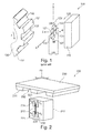
- FIG. 2 shows in a perspective view a magnetic field sensor system 200 according to an embodiment of the invention.
- the magnetic field sensor system 200 comprises a biasing magnet 210, an encoded soft magnetic wheel 230, and a magnetoresistive sensor arrangement 220, which is attached to a side surface of the biasing magnet 210.
- the biasing magnet 210 is made from a single permanent magnet which has a magnetization which in Figure 2 is indicated by the arrow 212.
- the biasing magnet 210 may also be made from different magnet pieces.
- the direction of the magnetization 212 is oriented parallel to the z-axis.
- the encoded soft magnetic wheel 230 has a circumferential surface which comprises a regular structure of teeth 231 and gaps 232, which are arranged in an alternating manner.
- the circumferential surface of the soft magnetic wheel 230 facing the biasing magnet 210 moves along the y-axis.
- the rotational axis of the encoded soft magnetic wheel 230 is oriented parallel to the x-axis and in Figure 2 is located above the depicted cutaway of the magnetic wheel 230.
- the magnetoresistive sensor arrangement 220 comprises four magnetoresistive sensor elements 221, 222, 223 and 224. According to the embodiment described here the magnetoresistive sensor arrangement 220 is located at a center of a side face of the biasing magnet 210. Further, the magnetoresistive sensor elements 221, 222, 223 and 224 can be arranged in a meandering pattern.
- the easy axis of magnetization of the magnetoresistive sensor elements 221, 222, 223,224 is the same as the longitudinal extension of the magnetoresistive sensor elements 221, 222, 223,224. This means that in the embodiment described here the easy axis of magnetization of the magnetoresistive sensor elements 221, 222, 223,224 is parallel to the z-axis.
- Figure 3 shows for the magnetic field sensor system of Figure 2 the used bar-berpole structure and the directions of the magnetizations M and the currents I in the magnetoresistive sensor elements 221, 222, 223 and 224, when the not depicted encoded soft magnetic wheel 230 (shown in Figure 2 ) is at a symmetrical position.
- the magnetization direction of the not depicted biasing magnet 210 (shown in Figure 2 ) is parallel to the z-axis.
- the presence of the soft magnetic wheel leads to a perturbation of the direction of the magnetization M of the magnetoresistive sensor elements 221, 222, 223 and 224.
- the two magnetoresistive sensor elements 221, 222 are located further away from the magnetic wheel as compared to the magnetoresistive sensor elements 223 and 224.
- the influence of the soft magnetic wheel on the magnetization of the magnetoresistive sensor elements 221, 222 is much smaller than the influence of the soft magnetic wheel on the magnetization of the magnetoresistive sensor elements 223 and 224.
- the main current directions I have a direction perpendicular to the direction of the barber poles.
- the barber pole structures all form an angle of 45° with respect to the z-axis.
- the current direction within all magnetoresistive sensor elements 221, 222, 223 and 224 also forms an angle of 45° with respect to the z-axis.
- the electric potential at the node b is also 0.5 Volt. Since the output signal of the magnetic field sensor system is the potential difference V(b) - V(a), one can conclude that at any symmetrical position of the magnetic wheel the output of the magnetic field sensor system will be zero.
- the described symmetry of the magnetoresistive sensor arrangement 220 does alone not cause a strong immunity of the magnetoresistive sensor arrangement to external magnetic fields. This immunity depends on the ratio between the magnetic field of the (passive) soft magnetic wheel and the magnetic field of the biasing magnet at the positions of the magnetoresistive sensor elements 221, 222, 223 and 224. In any realistic scenario this ratio cannot be bigger than 1/100.
- Figures 4a and 4b show the output signal of the magnetic field sensor system of Figure 2 in a symmetrical position of the soft magnetic wheel as a function of an external magnetic field H ext being directed parallel to the y-axis.
- Figure 4a shows the output signal when the ratio between the magnetic field of the passive magnetic wheel and the magnetic field of the bias magnet is 0.01.
- the output signal in a symmetrical position is too small to be distinguished from noise and will be considered as to be zero by a not depicted processing unit of the magnetic field sensor system.
- Figure 4b shows that even in case the magnetic field of the soft magnetic wheel gets 1/10 of the biasing magnetic field of the biasing magnet at the positions of the magnetoresistive sensor elements 221, 222, 223 and 224, the output signal of the magnetic field sensor system cannot exceed 0.1 mV/V and will also be interpreted as to be zero.
- the above mentioned condition according to which the z-component of the biasing magnetic field is equal for all magnetoresistive sensor elements 221, 222, 223, 224 can be fulfilled if the magnetization 512 of the biasing magnet 510 is not oriented exactly parallel to the z-axis but is oriented within the x-z plane.
- the x-component of the magnetization 512 makes sure that the z-component of the biasing magnetic field stays the same for all magnetoresistive sensor elements 221, 222, 223, 224.
- the stabilizing component of the biasing magnet 510 gets smaller thus making the respective magnetic field sensor system more sensitive.
- the signal strength will become larger, the larger the difference gets between the y-component of the magnetic field of the soft magnetic wheel at positions (a) of the magnetoresistive sensor elements 223, 224 on one side and (b) of the magnetoresistive sensor elements 221, 222 on the other side.
- the y-component of the magnetic field of the passive soft magnetic wheel is zero at the positions of the lower magnetoresistive sensor elements 221, 222. In this case the sensitivity of the magnetic field sensor system is maximal.
- the magnetic field difference of the y-component between the positions of the upper magnetoresistive sensor elements 223, 224 and the positions of the lower magnetoresistive sensor elements 221, 222 depends (among others) on the size of the magnetoresistive sensor arrangement 220 respectively on the size of the corresponding semiconductor die carrying the magnetoresistive sensor elements 221, 222, 223,224.
- the inventors performed two-dimensional FEM simulations of the spatial decay of the y-component of the magnetic field produced by the soft magnetic wheel along the z-axis. Thereby, it has been assumed that the distance between the upper magnetoresistive sensor elements 223, 224 and the lower magnetoresistive sensor elements 221, 222 is 1.5 mm. This is a typical size for a differential magnetic field sensor system.
- Figures 6a and 6b show the corresponding simulation results for two geometries of the biasing magnet.
- Figure 6a shows the result for a biasing magnet with the dimensions 12 mm x 1.5 mm. It can be seen that the y-component of the magnetic field produced by the soft magnetic wheel is more than 6 times smaller at the positions of the lower magnetoresistive sensor elements 221 and 222 as compared to the positions of the upper magnetoresistive sensor elements 223 and 224.
- Figure 6b shows the result for a biasing magnet with the dimensions 6 mm x 3 mm.
- the y-component of the magnetic field produced by the soft magnetic wheel is stronger and it declines more than 3 times over the 1.5 mm distance between (a) the upper magnetoresistive sensor elements 223 and 224 and (b) the lower magnetoresistive sensor elements 221 and 222.
- Figure 7 shows the corresponding results.
- the sensitivity of the differential sensors described in this document increases with the size of the magnetoresistive sensor arrangement along the z-axis. In Figure 7 this size is denominated AMR chip length.
- the sensitivity of the differential sensor gets almost half with respect to the sensitivity of a corresponding speed sensor.
- the sensitivity of the differential sensor described in this document is 3.5-4.5 mV/V for 1 mm air gap and 1.0-1.3 mV/V for 2 mm air gap.
- the air gap is the distance between (a) the soft magnetic wheel and (b) the surface of the biasing magnet and/or the magnetoresistive sensor arrangement, which surface is closest to the magnetic wheel.
- the described magnetic field sensor system can be realized with hall sensor elements or with magnetoresistive sensor elements such as e.g. AMR, GMR and/or TMR sensor elements.
- Magnetic field sensor system 110 biasing magnet 120 magnetoresistive sensor arrangement 121 magnetoresistive sensor element 122 magnetoresistive sensor element 123 magnetoresistive sensor element 124 magnetoresistive sensor element 126 first power supply terminal 130 encoded soft magnetic wheel 131 tooth / teeth 132 gap H biasing magnetic field F rotational motion coordinate / direction of rotational of shaft x x-axis / x-direction y y-axis / y-direction z z-axis / z-direction UA output signal UB first power supply potential M second power supply potential 200 magnetic field sensor system 210 biasing magnet 212 magnetization / direction of magnetization 220 magnetoresistive sensor arrangement 221 magnetoresistive sensor element 222 magnetoresistive sensor element 223 magnetoresistive sensor element 224 magnetoresistive sensor element 230 encoded soft magnetic wheel 231 tooth / teeth 232 gap 510 biasing magnet 512 magnetization / direction of magnetization
Landscapes
- Physics & Mathematics (AREA)
- General Physics & Mathematics (AREA)
- Condensed Matter Physics & Semiconductors (AREA)
- Measuring Magnetic Variables (AREA)
Abstract
Description
- The present invention generally relates to the technical field of magnetic field sensors. In particular, the present invention relates to a magnetic field sensor system comprising a biasing magnet, an encoded soft magnetic wheel having a teeth structure and magnetic sensor elements, which with the help of an appropriate evaluation electronic are capable of determining positional information of the encoded soft-magnetic wheel.
- Magnetic sensors are increasingly important in various industries. For instance in the automotive industry various sensors such as parking sensors, angular sensors e.g. in throttle valves, ABS (Automatic Braking System) sensors and tire pressure sensors can be found in modem vehicles for improving comfort and safety. Magnetic sensors are particularly important in automotive applications, because magnetic fields penetrate easily through most materials. Magnetic sensors are also highly insensitive to dirt, unlike for example optical sensors.
- Several different magnetic sensor technologies are currently available, such as magneto transistors (MT), sensors based on the Hall Effect and sensors based on the magnetoresistive effect such as anisotropic magnetoresistive (AMR) and giant magnetoresistive (GMR) sensors. The sensing principle of AMR sensors is based on the physical phenomenon that the electric resistance of a ferromagnetic material depends on the angle between the magnetization and the direction of the electric current within an AMR sensing element. Hall sensors and MTs, which rely on the Lorentz force, have a comparatively low sensitivity and consequently also a low accuracy. AMR sensors, while having a much higher sensitivity compared to Hall effect sensors and MTs, require more fabrication steps because they cannot easily be integrated monolithically, making a total sensor system more expensive.
- GMR sensors typically have a higher sensitivity than AMR sensors. However, a GMR sensor consists of various thin layers and critical interfaces. The technology required to fabricate such sensors is considerably more complicated and expensive. Furthermore, due to the thin multiple layers making up a GMR sensor, the operating temperature range is also limited. Therefore often AMR sensors are chosen as a good compromise in magnetic sensor applications.
-
US 7,141,967 B2 discloses a magnetic field sensor system for measuring the angular speed of a soft magnetic (gear) wheel attached for instance to the axis of a camshaft or crankshaft in a transmission system of a combustion engine. The disclosed magnetic field sensor system comprises a MR sensor arrangement consisting of four MR sensor elements which are electrically connected with each other in a so called Wheatstone bridge. The magnetic field sensor system further comprises a hard magnetic (permanent) magnet that produces a biasing magnetic field which magnetizes the wheel. In this respect soft magnetic means that the wheel has a high magnetic permeability and hard magnetic means that the magnet can be permanently magnetized. The hard magnet is predominately magnetized in a radial z-direction being oriented perpendicular to an x-y plane in which the four sensor elements are arranged. A periodic teeth-gap structure of the soft magnetic wheel produces periodic magnetic field changes when the wheel rotates. Since the MR sensor arrangement is sensitive to the y-component (Hy) of the magnetic field (H), this periodicity is visible in the output of the magnetic field sensor system. This signal can be used for determining the position and speed of the (gear) wheel and therefore of the parts of e.g. an engine to which the magnetic (gear) wheel is mechanically connected. - The magnetic field sensor system known from
US 7,141,967 B2 has the disadvantage that it has a small sensitivity. Further, a strong external magnetic field may have a negative impact on the output signal and on the reliability of the magnetic field sensor system. A high sensitivity and an immunity to homogenous external magnetic fields are required in particular when the magnetic field sensor system is used for determining the position and/or the speed of a crankshaft sensor because the starter motor in a start-stop system is typically located in the neighborhood of the crankshaft. - There may be a need for providing a magnetic sensor concept which on the one hand has a high sensitivity and on the other hand exhibits a high immunity with respect to external magnetic fields.
- This need may be met by the subject matter according to the
independent claim 1. Advantageous embodiments of the present invention are described by the dependent claims. - According to a first aspect of the invention there is provided a magnetic field sensor system for measuring rotational movements of a shaft. The provided magnetic field sensor system may be in particular a magnetic field differential sensor system The provided magnetic field sensor system comprises (a) a biasing magnet configured for generating a biasing magnetic field; (b) a magnetic wheel having a wheel axis and a circumferential surface which comprises a regular structure of teeth and gaps arranged in an alternating manner, wherein (i) the magnetic wheel is attachable to the shaft and (ii) the magnetic wheel can be magnetized by the biasing magnetic field; and (c) a magnetic sensor arrangement comprising four magnetic sensor elements being connected with each other in a Wheatstone bridge configuration. Respectively two of the magnetic sensor elements are assigned to one half bridge of the Wheatstone bridge. Further, the four magnetic sensor elements are arranged within an y-z plane, wherein an x-axis, a y-axis and a z-axis define an orthogonal Cartesian coordinate system in which (i) the x-axis is oriented parallel with the wheel axis of the magnetic wheel, (ii) the y-axis is oriented tangential to the circumferential surface of the magnetic wheel, and (iii) the z-axis is the symmetry line through the center of the biasing magnet and the center of the magnetic wheel.
- The described magnetic field sensor system is based on the idea that when placing the magnetic sensor elements within a plane being oriented perpendicular to the wheel axis an extreme high sensitivity of the magnetic field sensor system can be achieved while still having a very good suppression of the influence of external homogeneous magnetic fields on an output signal of the magnetic field sensor system.
- The described magnetic field sensor concept has the advantage that it works for any differential magnetic sensor having a large sensitivity in the y-z plane. Hence, like for anisotropic magnetoresistive (AMR) sensors, it also leads to convenient options for giant magnetoresistive (GMR) sensors, tunnel magnetoresistive (TMR) sensors and sensors based on magneto transistors (MT) for an absolute position and angle detection in magnetically-polluted environments. The described magnetic field sensor concept can also be realized with hall sensor elements.
- According to a further embodiment of the invention the magnetic sensor elements are oriented in such a manner that a first and a second one of the four magnetic sensor elements are located at a first distance from the magnetic wheel and a third and a fourth one of the four magnetic sensor elements are located at a second distance from the magnetic wheel, wherein the first distance is larger than the second distance.
- Descriptive speaking, the first magnetic sensor element and the second magnetic sensor element are positioned further away from the magnetic wheel than the third magnetic sensor element and the fourth magnetic sensor element. As a consequence, the influence of the magnetic wheel on the magnetic field being present at the respective magnetic sensor element is much smaller for the first and the second magnetic sensor element as compared to the third and the fourth magnetic sensor element.
- In a good approximation for the first and the second magnetic sensor element a modulation of the total magnetic field at the position of the respective sensor element caused by a rotation of the magnetic field is negligible compared to the strength of the biasing magnetic field. In other words, a rotation of the magnetic wheel will only modulate the total magnetic field at the positions of the third and the fourth magnetic sensor element in a significant extend. As a consequence, when taking into account a proper circuitry for the above described Wheatstone bridge, the sensitivity of the described magnetic field sensor system will be much higher than the sensitivity of known magnetic field sensor systems, which are also immune to homogeneous external magnetic fields.
- Specifically, the electric level of an electric node between the third and the forth magnetic sensor element will exhibit a comparatively strong modulation in response to a rotation of the magnetic wheel wherein the electric level of an electric node between the first and the second magnetic sensor element will stay approximately constant. Thereby, it is preferable if in accordance with the basic principles of a Wheatstone bridge (a) a first fixed voltage level is applied to an electric node between the first and the forth magnetic sensor element and (b) a second fixed voltage level is applied to an electric node between the second and the third magnetic sensor element. The first fixed voltage level may be e.g. 0 Volt and the second fixed voltage level may be e.g. 1 Volt.
- According to a further embodiment of the invention the magnetic sensor elements are formed on a single substrate die and in particular on a single semiconductor die. This may provide the advantage that the magnetic sensor arrangement consisting of the four magnetic sensor elements can be produced by means of a common semiconductor manufacturing process. This allows realizing the described magnetic field sensor system in an effective way with respect to the production costs.
- According to a further embodiment of the invention the magnetic sensor elements occupy an area smaller than 4 mm2, preferably smaller than 2 mm2 and more preferably smaller than 1 mm2. This may provide the advantage that the production costs for the single substrate or semiconductor die and, as a consequence also for the whole magnetic field sensor system, can be kept small.
- According to an embodiment of the invention a direction of a magnetization of the biasing magnet is oriented parallel to the x-z plane. This may provide the advantage that when the magnetic wheel is in a symmetric angular position, the output signal provided by the magnetic field sensor system is zero. With this characteristic of the described magnetic field sensor system an important requirement for a sensor being suitable for measuring e.g. the rotational speed and/or the rotational position of a crankshaft of a combustion engine can be fulfilled.
- In this respect "symmetric angular position" may mean that with respect to a circumferential direction of the magnetic wheel the center of a tooth or the center of a gap coincides with the z-axis. In other words, the term "symmetric angular position" may mean that a gap or a tooth of the magnetic wheel is located exactly and symmetrically between the biasing magnet and the wheel axis.
- According to a further embodiment of the invention the biasing magnet has a side face being oriented perpendicular to the x-axis. Further, the magnetic sensor elements are placed at the side face of that biasing magnet. This may provide the advantage that the magnetic sensor elements can be easily mechanically supported by the biasing magnet. There is no need for any further mechanical structures being used for carrying and/or supporting the magnetic sensor elements at their respective spatial position.
- The magnetic sensor elements may be attached to the biasing magnet in any possible manner. In particular, the magnetoresistive sensor elements may be glued to the side face of the biasing magnet.
- According to a further embodiment of the invention the magnetic sensor elements are magnetoresistive sensor elements and the magnetic sensor arrangement is a magnetoresistive sensor arrangement. This may provide the advantage that the magnetic field sensor system can show an extreme high sensitivity while still being immune to external homogenous magnetic fields. The magnetoresistive sensor elements may be in particular AMR sensor elements.
- According to a further embodiment of the invention the magnetoresistive sensor elements are oriented in such a manner that their easy axis of magnetization is oriented parallel to the direction of the local biasing magnetic field. This may provide the advantage that a disturbing influence of external homogenous magnetic (stray) fields can be perfectly suppressed while a very good sensitivity of the described magnetic field sensor system can be maintained.
- In this respect "local biasing magnetic field" is the biasing magnetic field at the position of the respective magnetoresistive sensor element.
- It is mentioned that the described orientation of the magnetoresistive sensor elements can be realized in particular if a longitudinal axis of the magnetoresistive sensor elements, which longitudinal axis defines the direction along which the magnetoresistive sensor elements have their longest extension, is oriented parallel to the direction of the biasing magnetic field.
- According to a further embodiment of the invention the magnetoresistive sensor elements experience the same z-component of the biasing magnetic field. By selecting the magnetization direction and/or the spatial positions of the four magnetoresistive sensor elements in such a manner that at the locations of the four magnetoresistive sensor elements the z-component of the local biasing magnetic field is at least approximately the same, the immunity of the magnetic field sensor system to external homogenous magnetic field will be further increased.
- According to a further embodiment of the invention the magnetoresistive sensor arrangement is located at a center of the side face of the biasing magnet. With such a configuration it may be very easy to place the magnetoresistive sensor elements at their proper positions. Thereby, it can be ensured that the above mentioned advantages (a) of a zero output when the magnetic wheel is in a symmetric position and/or (b) of an extended immunity against external homogenous fields can be easily achieved.
- According to a further embodiment of the invention the direction of the magnetization of the biasing magnet is oriented exclusively parallel to the z-axis. This may mean in other words that the x- and the y-components of the magnetization are at least approximately zero. Thereby, the described magnetic field sensor system can be realized with a very simple geometry. It will not be necessary to orient the biasing magnet and/or the magnetization direction of the biasing magnet inclined or oblique with respect to any one of the three axes of the above mentioned Cartesian coordinate system of the described magnetic field sensor system.
- According to a further embodiment of the invention the easy axis of magnetization of the magnetoresistive sensor elements is oriented exclusively parallel to the direction of the magnetization of the biasing magnet.
- As has already been mentioned above the described orientation of the magnetoresistive sensor elements can be realized in particular if a longitudinal axis of the respective magnetoresistive sensor element, which longitudinal axis defines the direction along which the magnetoresistive sensor element has its longest extension, is oriented at least substantially parallel to the direction of the magnetization of the biasing magnet respectively to the z-axis.
- According to a further embodiment of the invention the magnetoresistive sensor arrangement is located offset of a center of the side face of the biasing magnet. Depending on the spatial dimension of the magnetoresistive sensor arrangement and/or of the biasing magnet two of the magnetoresistive sensor elements can be located very close to the edge of (the respective side face of) the biasing magnet. Since the influence of the magnetic wheel onto the total local magnetic field at the locations of these two magnetoresistive sensor elements is particularly high, the sensitivity of the magnetic field sensor can be further improved.
- According to a further embodiment of the invention the direction of the magnetization of the biasing magnet is oriented within the x-z plane, wherein an x-component of the magnetization is larger than zero. The x-component of the magnetization may make sure that the z-component of the biasing magnetic field stays the same for all four magnetoresistive sensor elements. Further, a stabilizing component of the biasing magnetic field can get smaller thus making the described magnetic field sensor system even more sensitive.
- The aspects defined above and further aspects of the present invention are apparent from the examples of embodiment to be described hereinafter and are explained with reference to the examples of embodiment. The invention will be described in more detail hereinafter with reference to examples of embodiment but to which the invention is not limited.
-
-
Figure 1 shows a known magnetic field sensor system for illustrating the basic physical principles of sensing a rotational movement by means of a magnetoresistive sensor arrangement comprising four magnetoresistive sensor elements. -
Figure 2 shows in a perspective view a magnetic field sensor system, wherein in accordance with an embodiment of the invention a magnetoresistive sensor arrangement is located at a center of a side face of a biasing magnet. -
Figure 3 shows for the magnetic field sensor system ofFigure 2 the used bar-berpole structure and the directions of the magnetizations and the currents in the magnetoresistive sensor elements, when the magnetic wheel is at a symmetrical position. -
Figures 4a and 4b show the output signal of the magnetic field sensor system ofFigure 2 in a symmetrical position of the wheel as a function of an external magnetic field being directed parallel to the y-axis. -
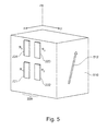
Figure 5 shows in a perspective view a biasing magnet with a magnetoresistive sensor arrangement attached thereto, wherein in accordance with an embodiment of the invention the magnetoresistive sensor arrangement is located offset with respect to a center of a side face of a biasing magnet. -
Figures 6a and 6b show for two geometries of the biasing magnet the spatial decay of the y-component of the magnetic field produced by the magnetic wheel along the z-axis. -
Figure 7 shows the ratio between (a) the sensitivity of the magnetic field sensor systems (differential sensor) described in this document and (b) the sensitivity of a speed sensor as a function of the length of the chip carrying the magnetoresistive sensor elements. - The illustration in the drawing is schematically. It is noted that in different figures, similar or identical elements or features are provided with the same reference signs or with reference signs, which are different from the corresponding reference signs only within the first digit. In order to avoid unnecessary repetitions elements or features which have already been elucidated with respect to a previously described embodiment are not elucidated again at a later position of the description.
-
Figure 1 shows a known magneticfield sensor system 100 for illustrating the basic physical principles of sensing a rotational movement by means of amagnetoresistive sensor arrangement 120 comprising fourmagnetoresistive sensor elements Figure 1 , the magneticfield sensor system 100 comprises abiasing magnet 110 producing a biasing magnetic field H, the already mentionedmagnetoresistive sensor arrangement 120 and an encoded softmagnetic wheel 130 having a circumferential surface which comprises a regular structure ofteeth 131 andgaps 132 arranged in an alternating manner. - The
magnetic wheel 130 can be attached to a not depicted shaft, e.g. a camshaft or a crankshaft in a transmission system of a combustion engine. This shaft is oriented along an x-direction. Its corresponding rotation is indicated inFigure 1 with the curved arrow denominated with the rotational motion coordinate F. - The
magnetoresistive sensor elements power supply terminal 126, to which in operation a first power supply potential UB is applied, and a secondpower supply terminal 127, to which in operation a second power supply potential M, preferably ground potential, is applied. Thesensor arrangement 120 is planar arranged in an x-y plane defined by an x-axis and a y-axis of an orthogonal Cartesian system of coordinates. A z-axis of the Cartesian system is oriented perpendicular to the x-y plane. - The biasing
magnet 110 has a rectangular geometry and is preferably stuck to a rear side of thesensor arrangement 120 or its housing so that thesensor arrangement 120 is permeated by the biasing magnetic field H. Themagnetoresistive sensor arrangement 120 has a measuring direction along the y-axis. Along this measuring direction, it is sensitive to the polarity and the field strength of an external magnetic field and is adapted to supply a measuring signal in dependence upon a field component of this magnetic field, denoted as measuring field and measured in the measuring direction. For operation, the external magnetic field is preferably and exclusively formed by the magnetic field H of the biasingmagnet 110. - To measure the rotational speed of a shaft by means of the
magnetoresistive sensor arrangement 120, the encoded softmagnetic wheel 130 described hereinbefore is positioned in front of thesensor arrangement 120 in the direction of the z-axis. In operation thewheel 130 being formed from a ferromagnetic material which can be magnetized by the biasing magnetic field H rotates in the direction of the motion coordinate F. Along the motion coordinate F of themagnetic wheel 130, this leads to a distortion of the field lines of the biasing magnetic field H of the biasingmagnet 110 in the measuring direction of thesensor arrangement 120, situated in the direction of the y-axis, which distortion occurs periodically with respect to the distance between theteeth 131 or themagnetic wheel 130. The field component of the magnetic field H of the measuring direction situated in the direction of the y-axis is denoted as measuring field. - In the
magnetoresistive sensor arrangement 120, the measuring field generates a preferably at least substantially sinusoidal output signal UA via the motion coordinate F of the encoded softmagnetic wheel 130. -
Figure 2 shows in a perspective view a magneticfield sensor system 200 according to an embodiment of the invention. The magneticfield sensor system 200 comprises abiasing magnet 210, an encoded softmagnetic wheel 230, and amagnetoresistive sensor arrangement 220, which is attached to a side surface of the biasingmagnet 210. - According to the embodiment described here the biasing
magnet 210 is made from a single permanent magnet which has a magnetization which inFigure 2 is indicated by thearrow 212. However, the biasingmagnet 210 may also be made from different magnet pieces. As can be seen fromFigure 2 , according to the embodiment described here the direction of themagnetization 212 is oriented parallel to the z-axis. - The encoded soft
magnetic wheel 230 has a circumferential surface which comprises a regular structure ofteeth 231 andgaps 232, which are arranged in an alternating manner. In accordance with the magneticfield sensor system 100 shown inFigure 1 also in the magneticfield sensor system 200 which is shown inFigure 2 the circumferential surface of the softmagnetic wheel 230 facing the biasingmagnet 210 moves along the y-axis. The rotational axis of the encoded softmagnetic wheel 230 is oriented parallel to the x-axis and inFigure 2 is located above the depicted cutaway of themagnetic wheel 230. - The
magnetoresistive sensor arrangement 220 comprises fourmagnetoresistive sensor elements magnetoresistive sensor arrangement 220 is located at a center of a side face of the biasingmagnet 210. Further, themagnetoresistive sensor elements - It is mentioned that in
Figure 2 connections between themagnetoresistive sensor elements magnetoresistive sensor elements - It is mentioned that the easy axis of magnetization of the
magnetoresistive sensor elements magnetoresistive sensor elements magnetoresistive sensor elements -
Figure 3 shows for the magnetic field sensor system ofFigure 2 the used bar-berpole structure and the directions of the magnetizations M and the currents I in themagnetoresistive sensor elements Figure 2 ) is at a symmetrical position. - In accordance with
Figure 2 , the magnetization direction of the not depicted biasing magnet 210 (shown inFigure 2 ) is parallel to the z-axis. However, the presence of the soft magnetic wheel leads to a perturbation of the direction of the magnetization M of themagnetoresistive sensor elements magnetoresistive sensor elements magnetoresistive sensor elements magnetoresistive sensor elements magnetoresistive sensor elements Figure 3 , where the angle between the z-axis and the magnetization directions M of themagnetoresistive sensor elements magnetoresistive sensor elements - In accordance with the physical principles of barber pole structures which in
Figure 3 are indicated with angular hatchings the main current directions I have a direction perpendicular to the direction of the barber poles. According to the embodiment described here the barber pole structures all form an angle of 45° with respect to the z-axis. Accordingly, the current direction within allmagnetoresistive sensor elements - From
Figure 3 it can be easily seen that in any symmetrical position of the magnetic wheel the magnetic field sensor system generates a zero output signal between a node a and a node b of themagnetoresistive sensor arrangement 220. Indeed, due to symmetry, the angles between magnetization M and current direction I in the lowermagnetoresistive sensor elements magnetoresistive sensor elements magnetoresistive sensor elements magnetoresistive sensor elements magnetoresistive sensor elements - However, the described symmetry of the
magnetoresistive sensor arrangement 220 does alone not cause a strong immunity of the magnetoresistive sensor arrangement to external magnetic fields. This immunity depends on the ratio between the magnetic field of the (passive) soft magnetic wheel and the magnetic field of the biasing magnet at the positions of themagnetoresistive sensor elements -
Figures 4a and 4b show the output signal of the magnetic field sensor system ofFigure 2 in a symmetrical position of the soft magnetic wheel as a function of an external magnetic field Hext being directed parallel to the y-axis.Figure 4a shows the output signal when the ratio between the magnetic field of the passive magnetic wheel and the magnetic field of the bias magnet is 0.01. One can see that the output signal in a symmetrical position is too small to be distinguished from noise and will be considered as to be zero by a not depicted processing unit of the magnetic field sensor system.Figure 4b shows that even in case the magnetic field of the soft magnetic wheel gets 1/10 of the biasing magnetic field of the biasing magnet at the positions of themagnetoresistive sensor elements - Calculations, which have been performed by the inventors of the magnetic field sensor systems described in this document, show that a strong immunity to the external magnetic fields requires that the z-component of the biasing magnetic field is the same for all
magnetoresistive sensor elements magnetoresistive sensor elements Figure 5 . - In case the
magnetoresistive sensor arrangement 220 is placed at the side face of the biasingmagnet 510 off center, the above mentioned condition according to which the z-component of the biasing magnetic field is equal for allmagnetoresistive sensor elements magnetization 512 of the biasingmagnet 510 is not oriented exactly parallel to the z-axis but is oriented within the x-z plane. Thereby, the x-component of themagnetization 512 makes sure that the z-component of the biasing magnetic field stays the same for allmagnetoresistive sensor elements magnet 510 gets smaller thus making the respective magnetic field sensor system more sensitive. - For the described magnetic field sensor system the signal strength will become larger, the larger the difference gets between the y-component of the magnetic field of the soft magnetic wheel at positions (a) of the
magnetoresistive sensor elements magnetoresistive sensor elements magnetoresistive sensor elements magnetoresistive sensor elements magnetoresistive sensor elements magnetoresistive sensor arrangement 220 respectively on the size of the corresponding semiconductor die carrying themagnetoresistive sensor elements - In order to get a better knowledge about the influence of the size of the
magnetoresistive sensor arrangement 220 the inventors performed two-dimensional FEM simulations of the spatial decay of the y-component of the magnetic field produced by the soft magnetic wheel along the z-axis. Thereby, it has been assumed that the distance between the uppermagnetoresistive sensor elements magnetoresistive sensor elements -
Figures 6a and 6b show the corresponding simulation results for two geometries of the biasing magnet.Figure 6a shows the result for a biasing magnet with thedimensions 12 mm x 1.5 mm. It can be seen that the y-component of the magnetic field produced by the soft magnetic wheel is more than 6 times smaller at the positions of the lowermagnetoresistive sensor elements magnetoresistive sensor elements Figure 6b shows the result for a biasing magnet with thedimensions 6 mm x 3 mm. The y-component of the magnetic field produced by the soft magnetic wheel is stronger and it declines more than 3 times over the 1.5 mm distance between (a) the uppermagnetoresistive sensor elements magnetoresistive sensor elements - However, in reality, the spatial decay of the y-component of the magnetic field produced by the soft magnetic wheel is much stronger since the mentioned FEM simulations are only two-dimensional and correspondingly assume that the biasing magnet and the soft magnetic wheel are infinite in the third dimension (here the x-direction).
- However, one can translate the spatial decay of the y-component of the magnetic field produced by the soft magnetic wheel to the ratio between (a) the sensitivity of the differential sensors described in this document and (b) the sensitivity of a corresponding conventional speed sensor (see
Figure 1 ). -
Figure 7 shows the corresponding results. As one can see on theFigure 7 , the sensitivity of the differential sensors described in this document increases with the size of the magnetoresistive sensor arrangement along the z-axis. InFigure 7 this size is denominated AMR chip length. In case of a biasing magnet with dimensions 1.5 mm x 12 mm and a sensor length along the z-axis of 1.8 mm, the sensitivity of the differential sensor gets almost half with respect to the sensitivity of a corresponding speed sensor. This means that the sensitivity of the differential sensor described in this document is 3.5-4.5 mV/V for 1 mm air gap and 1.0-1.3 mV/V for 2 mm air gap. In this respect the air gap is the distance between (a) the soft magnetic wheel and (b) the surface of the biasing magnet and/or the magnetoresistive sensor arrangement, which surface is closest to the magnetic wheel. - In order to recapitulate the above described embodiments of the present invention one can conclude: In this document there is described a magnetic field sensor system that has zero output in symmetrical positions of the soft magnetic wheel, that is very robust against external magnetic fields, and that is very sensitive. Ideally the described magnetic field sensor system should be only twice less sensitive then a corresponding speed sensor. This is a very good result for a sensor concept which is highly immune to external magnetic fields.
- The described magnetic field sensor system can be realized with hall sensor elements or with magnetoresistive sensor elements such as e.g. AMR, GMR and/or TMR sensor elements.
- It should be noted that the term "comprising" does not exclude other elements or steps and "a" or "an" does not exclude a plurality. Also elements described in association with different embodiments may be combined. It should also be noted that reference signs in the claims should not be construed as limiting the scope of the claims.
Reference Numerals: 100 magnetic field sensor system 110 biasing magnet 120 magnetoresistive sensor arrangement 121 magnetoresistive sensor element 122 magnetoresistive sensor element 123 magnetoresistive sensor element 124 magnetoresistive sensor element 126 first power supply terminal 130 encoded soft magnetic wheel 131 tooth / teeth 132 gap H biasing magnetic field F rotational motion coordinate / direction of rotational of shaft x x-axis / x-direction y y-axis / y-direction z z-axis / z-direction UA output signal UB first power supply potential M second power supply potential 200 magnetic field sensor system 210 biasing magnet 212 magnetization / direction of magnetization 220 magnetoresistive sensor arrangement 221 magnetoresistive sensor element 222 magnetoresistive sensor element 223 magnetoresistive sensor element 224 magnetoresistive sensor element 230 encoded soft magnetic wheel 231 tooth / teeth 232 gap 510 biasing magnet 512 magnetization / direction of magnetization
Claims (14)
- A magnetic field sensor system for measuring rotational movements of a shaft, the magnetic field sensor system (200) comprising:a biasing magnet (210, 510) configured for generating a biasing magnetic field;a magnetic wheel (230) having a wheel axis and a circumferential surface which comprises a regular structure of teeth (231) and gaps (232) arranged in an alternating manner, wherein(i) the magnetic wheel (230) is attachable to the shaft and(ii) the magnetic wheel (230) can be magnetized by the biasing magnetic field; anda magnetic sensor arrangement (220) comprising four magnetic sensor elements (221, 222, 223, 224) being connected with each other in a Wheatstone bridge configuration, respectively two of the magnetic sensor elements (221, 222, 223, 224) being assigned to one half bridge of the Wheatstone bridge, whereinthe four magnetic sensor elements (221, 222, 223, 224) are arranged within an y-z plane, wherein an x-axis, a y-axis and a z-axis define an orthogonal Cartesian coordinate system in which (i) the x-axis is oriented parallel with the wheel axis of the magnetic wheel (230), (ii) the y-axis is oriented tangential to the circumferential surface of the magnetic wheel (230), and (iii) the z-axis is the symmetry line through the center of the biasing magnet (210, 510) and the center of the magnetic wheel (230).
- The magnetic field sensor system as set forth in any one of the preceding claims, wherein
the magnetic sensor elements (221, 222, 223, 224) are oriented in such a manner that a first (221) and a second (222) one of the four magnetic sensor elements are located at a first distance from the magnetic wheel (230) and a third (223) and a fourth (224) one of the four magnetic sensor elements are located at a second distance from the magnetic wheel (230), wherein the first distance is larger than the second distance. - The magnetic field sensor system as set forth in any one of the preceding claims, wherein
the magnetic sensor elements (221, 222, 223, 224) are formed on a single substrate die. - The magnetic field sensor system as set forth in the preceding claim, wherein
the magnetic sensor elements (221, 222, 223, 224) occupy an area smaller than 4 mm2, preferably smaller than 2 mm2 and more preferably smaller than 1 mm2. - The magnetic field sensor system as set forth in any one of the preceding claims, wherein
a direction of a magnetization of the biasing magnet (210, 510) is oriented parallel to the x-z plane. - The magnetic field sensor system as set forth in any one of the preceding claims, wherein
the biasing magnet (210, 510) has a side face being oriented perpendicular to the x-axis and wherein
the magnetic sensor elements (221, 222, 223, 224) are placed at the side face of the biasing magnet (210, 510). - The magnetic field sensor system as set forth in any one of the preceding claims, wherein
the magnetic sensor elements are magnetoresistive sensor elements (221, 222, 223, 224) and the magnetic sensor arrangement is a magnetoresistive sensor arrangement (220). - The magnetic field sensor system as set forth in the preceding claim 7, wherein
the magnetoresistive sensor elements (221, 222, 223, 224) are oriented in such a manner that their easy axis of magnetization is oriented parallel to the direction of the local biasing magnetic field. - The magnetic field sensor system as set forth in any one of the preceding claims 7 and 8, wherein
the magnetoresistive sensor elements (221, 222, 223, 224) experience the same z-component of the biasing magnetic field. - The magnetic field sensor system as set forth in any one of the preceding claims 7 to 9, wherein
the magnetoresistive sensor arrangement (220) is located at a center of the side face of the biasing magnet (210). - The magnetic field sensor system as set forth in the preceding claim, wherein
the direction of the magnetization (212) of the biasing magnet (210) is oriented exclusively parallel to the z-axis. - The magnetic field sensor system as set forth in the claims 10 to 1 l, wherein
the easy axis of magnetization of the magnetoresistive sensor elements (221, 222, 223, 224) is oriented exclusively parallel to the direction of the magnetization of the biasing magnet (210). - The magnetic field sensor system as set forth in any one of the preceding claims 7 to 9, wherein
the magnetoresistive sensor arrangement (220) is located offset of a center of the side face of the biasing magnet (510). - The magnetic field sensor system as set forth in the preceding claim, wherein
the direction of the magnetization (512) of the biasing magnet (510) is oriented within the x-z plane, wherein an x-component of the magnetization is larger than zero.
Priority Applications (2)
| Application Number | Priority Date | Filing Date | Title |
|---|---|---|---|
| EP13155906.4A EP2770303B1 (en) | 2013-02-20 | 2013-02-20 | Magnetic field sensor system with a magnetic wheel rotatable around a wheel axis and with magnetic sensor elements being arranged within a plane perpendicular to the wheel axis |
| US14/177,994 US9347799B2 (en) | 2013-02-20 | 2014-02-11 | Magnetic field sensor system with a magnetic wheel rotatable around a wheel axis and with magnetic sensor elements being arranged within a plane perpendicular to the wheel axis |
Applications Claiming Priority (1)
| Application Number | Priority Date | Filing Date | Title |
|---|---|---|---|
| EP13155906.4A EP2770303B1 (en) | 2013-02-20 | 2013-02-20 | Magnetic field sensor system with a magnetic wheel rotatable around a wheel axis and with magnetic sensor elements being arranged within a plane perpendicular to the wheel axis |
Publications (2)
| Publication Number | Publication Date |
|---|---|
| EP2770303A1 true EP2770303A1 (en) | 2014-08-27 |
| EP2770303B1 EP2770303B1 (en) | 2017-04-12 |
Family
ID=47722162
Family Applications (1)
| Application Number | Title | Priority Date | Filing Date |
|---|---|---|---|
| EP13155906.4A Not-in-force EP2770303B1 (en) | 2013-02-20 | 2013-02-20 | Magnetic field sensor system with a magnetic wheel rotatable around a wheel axis and with magnetic sensor elements being arranged within a plane perpendicular to the wheel axis |
Country Status (2)
| Country | Link |
|---|---|
| US (1) | US9347799B2 (en) |
| EP (1) | EP2770303B1 (en) |
Cited By (2)
| Publication number | Priority date | Publication date | Assignee | Title |
|---|---|---|---|---|
| JP2016109472A (en) * | 2014-12-03 | 2016-06-20 | 浜松光電株式会社 | Magnetic sensor |
| WO2019168645A1 (en) * | 2018-03-01 | 2019-09-06 | Allegro Microsystems, Llc | Magnetic field influence during rotation movement of magnetic target |
Families Citing this family (38)
| Publication number | Priority date | Publication date | Assignee | Title |
|---|---|---|---|---|
| US9823090B2 (en) | 2014-10-31 | 2017-11-21 | Allegro Microsystems, Llc | Magnetic field sensor for sensing a movement of a target object |
| US10495699B2 (en) | 2013-07-19 | 2019-12-03 | Allegro Microsystems, Llc | Methods and apparatus for magnetic sensor having an integrated coil or magnet to detect a non-ferromagnetic target |
| US9810519B2 (en) * | 2013-07-19 | 2017-11-07 | Allegro Microsystems, Llc | Arrangements for magnetic field sensors that act as tooth detectors |
| US10145908B2 (en) | 2013-07-19 | 2018-12-04 | Allegro Microsystems, Llc | Method and apparatus for magnetic sensor producing a changing magnetic field |
| EP2960666B1 (en) * | 2014-06-25 | 2017-01-25 | Nxp B.V. | Sensor system with a three half-bridge configuration |
| US10353021B2 (en) * | 2014-07-25 | 2019-07-16 | Mitsubishi Electric Corporation | Magnetic sensor device |
| US9823092B2 (en) | 2014-10-31 | 2017-11-21 | Allegro Microsystems, Llc | Magnetic field sensor providing a movement detector |
| US10712403B2 (en) | 2014-10-31 | 2020-07-14 | Allegro Microsystems, Llc | Magnetic field sensor and electronic circuit that pass amplifier current through a magnetoresistance element |
| US9857438B2 (en) | 2015-04-20 | 2018-01-02 | Infineon Technologies Ag | Magnetoresistive devices |
| US10254303B2 (en) * | 2016-05-09 | 2019-04-09 | Infineon Technologies Ag | Twist independent mounting of a wheel speed sensor using a differential magnetoresistive sensor |
| US10260905B2 (en) | 2016-06-08 | 2019-04-16 | Allegro Microsystems, Llc | Arrangements for magnetic field sensors to cancel offset variations |
| US10041810B2 (en) | 2016-06-08 | 2018-08-07 | Allegro Microsystems, Llc | Arrangements for magnetic field sensors that act as movement detectors |
| US10597118B2 (en) | 2016-09-12 | 2020-03-24 | Kai Concepts, LLC | Watercraft device with hydrofoil and electric propeller system |
| JP6926502B2 (en) * | 2017-02-10 | 2021-08-25 | 日立金属株式会社 | Rotation sensor for turbo and turbocharger |
| FR3069636B1 (en) * | 2017-07-25 | 2019-10-04 | Continental Automotive France | METHOD AND DEVICE FOR DETECTING INVERSION OF A CRANKSHAFT SENSOR |
| FR3069635B1 (en) * | 2017-07-25 | 2019-08-02 | Continental Automotive France | AUTOMATIC CALIBRATION METHOD OF CAMSHAFT SENSOR FOR MOTOR VEHICLE ENGINE |
| US10539432B2 (en) | 2018-01-29 | 2020-01-21 | Infineon Technologies Ag | Differential top-read magnetic sensor with low cost back bias magnet |
| US11248971B2 (en) * | 2018-02-02 | 2022-02-15 | Analog Devices International Unlimited Company | Magnetic field torque and/or angle sensor |
| KR102688774B1 (en) | 2018-02-16 | 2024-07-26 | 아날로그 디바이시즈 글로벌 언리미티드 컴퍼니 | Position sensor and position sensing method |
| US11255700B2 (en) | 2018-08-06 | 2022-02-22 | Allegro Microsystems, Llc | Magnetic field sensor |
| US10823586B2 (en) | 2018-12-26 | 2020-11-03 | Allegro Microsystems, Llc | Magnetic field sensor having unequally spaced magnetic field sensing elements |
| US10837753B2 (en) * | 2019-01-10 | 2020-11-17 | Allegro Microsystems, Llc | Magnetic field sensor using MR elements for detecting flux line divergence |
| US11131567B2 (en) | 2019-02-08 | 2021-09-28 | Honda Motor Co., Ltd. | Systems and methods for error detection in crankshaft tooth encoding |
| US11181016B2 (en) * | 2019-02-08 | 2021-11-23 | Honda Motor Co., Ltd. | Systems and methods for a crank sensor having multiple sensors and a magnetic element |
| US11199426B2 (en) | 2019-02-08 | 2021-12-14 | Honda Motor Co., Ltd. | Systems and methods for crankshaft tooth encoding |
| US11162444B2 (en) | 2019-02-08 | 2021-11-02 | Honda Motor Co., Ltd. | Systems and methods for a crank sensor having multiple sensors and a magnetic element |
| US11280637B2 (en) | 2019-11-14 | 2022-03-22 | Allegro Microsystems, Llc | High performance magnetic angle sensor |
| US11237020B2 (en) | 2019-11-14 | 2022-02-01 | Allegro Microsystems, Llc | Magnetic field sensor having two rows of magnetic field sensing elements for measuring an angle of rotation of a magnet |
| US12246811B2 (en) * | 2020-04-22 | 2025-03-11 | Kai Concepts, LLC | Watercraft device with a handheld controller |
| US11897583B2 (en) * | 2020-04-22 | 2024-02-13 | Kai Concepts, LLC | Watercraft device with hydrofoil and electric propulsion system |
| CN114236170B (en) * | 2020-09-09 | 2024-06-28 | 江苏多维科技有限公司 | A wheel speed sensor module |
| US11637482B2 (en) | 2020-10-08 | 2023-04-25 | Analog Devices International Unlimited Company | Magnetic sensor system for motor control |
| US11460323B2 (en) | 2021-02-05 | 2022-10-04 | Analog Devices International Unlimited Company | Magnetic field sensor package |
| US11959820B2 (en) | 2021-03-17 | 2024-04-16 | Honda Motor Co., Ltd. | Pulser plate balancing |
| EP4187208B1 (en) * | 2021-11-24 | 2025-10-29 | ABB Schweiz AG | Assembly and method for position detection with error detection with a position sensor |
| DE102022200055A1 (en) * | 2022-01-05 | 2023-07-06 | Robert Bosch Gesellschaft mit beschränkter Haftung | Magnetic sensor unit and magnetic sensor arrangement |
| US12326351B2 (en) * | 2022-10-07 | 2025-06-10 | Infineon Technologies Ag | Linear tunnel magnetoresistive sensor including an integrated back-bias magnet |
| WO2024173165A2 (en) | 2023-02-14 | 2024-08-22 | Kai Concepts, LLC | Watercraft device with a handheld controller |
Citations (6)
| Publication number | Priority date | Publication date | Assignee | Title |
|---|---|---|---|---|
| EP0419040A1 (en) * | 1989-09-19 | 1991-03-27 | Texas Instruments Incorporated | Speed/position sensor based upon magnetoresistive effect |
| DE10056515A1 (en) * | 1999-11-25 | 2001-05-31 | Denso Corp | Rotation detector for use in motor control and antiblocking brake system of vehicle has second MRE in first MRE circuit and fourth MRE in second MRE circuit symmetrical with regard to central line |
| US20050007105A1 (en) * | 2003-07-11 | 2005-01-13 | Henrik Siegle | Device for detecting the rotational speed and/or the position of a rotating component |
| US20060261801A1 (en) * | 2005-05-20 | 2006-11-23 | Honeywell International Inc. | Magnetoresistive sensor |
| US7141967B2 (en) | 2001-11-27 | 2006-11-28 | Koninklijke Philips Electronics N.V. | Sensor arrangement |
| DE102010020027A1 (en) * | 2009-10-30 | 2011-05-05 | Mitsubishi Electric Corp. | Magnetic detection device |
Family Cites Families (3)
| Publication number | Priority date | Publication date | Assignee | Title |
|---|---|---|---|---|
| DE3132549A1 (en) * | 1981-08-18 | 1983-03-03 | Robert Bosch Gmbh, 7000 Stuttgart | DEVICE FOR DETECTING THE SPEED OF ROTATING PARTS |
| JP3186403B2 (en) * | 1993-03-11 | 2001-07-11 | 富士通株式会社 | Magnetic sensor and signal conversion circuit |
| EP2713140B1 (en) * | 2012-09-26 | 2014-10-08 | Nxp B.V. | Magnetic field sensor system with a biasing magnet producing a spatially symmetric magnetic field within a plane being defined by magnetoresistive sensor elements |
-
2013
- 2013-02-20 EP EP13155906.4A patent/EP2770303B1/en not_active Not-in-force
-
2014
- 2014-02-11 US US14/177,994 patent/US9347799B2/en not_active Expired - Fee Related
Patent Citations (6)
| Publication number | Priority date | Publication date | Assignee | Title |
|---|---|---|---|---|
| EP0419040A1 (en) * | 1989-09-19 | 1991-03-27 | Texas Instruments Incorporated | Speed/position sensor based upon magnetoresistive effect |
| DE10056515A1 (en) * | 1999-11-25 | 2001-05-31 | Denso Corp | Rotation detector for use in motor control and antiblocking brake system of vehicle has second MRE in first MRE circuit and fourth MRE in second MRE circuit symmetrical with regard to central line |
| US7141967B2 (en) | 2001-11-27 | 2006-11-28 | Koninklijke Philips Electronics N.V. | Sensor arrangement |
| US20050007105A1 (en) * | 2003-07-11 | 2005-01-13 | Henrik Siegle | Device for detecting the rotational speed and/or the position of a rotating component |
| US20060261801A1 (en) * | 2005-05-20 | 2006-11-23 | Honeywell International Inc. | Magnetoresistive sensor |
| DE102010020027A1 (en) * | 2009-10-30 | 2011-05-05 | Mitsubishi Electric Corp. | Magnetic detection device |
Cited By (4)
| Publication number | Priority date | Publication date | Assignee | Title |
|---|---|---|---|---|
| JP2016109472A (en) * | 2014-12-03 | 2016-06-20 | 浜松光電株式会社 | Magnetic sensor |
| WO2019168645A1 (en) * | 2018-03-01 | 2019-09-06 | Allegro Microsystems, Llc | Magnetic field influence during rotation movement of magnetic target |
| US10866117B2 (en) | 2018-03-01 | 2020-12-15 | Allegro Microsystems, Llc | Magnetic field influence during rotation movement of magnetic target |
| US11313700B2 (en) | 2018-03-01 | 2022-04-26 | Allegro Microsystems, Llc | Magnetic field influence during rotation movement of magnetic target |
Also Published As
| Publication number | Publication date |
|---|---|
| US20140232379A1 (en) | 2014-08-21 |
| EP2770303B1 (en) | 2017-04-12 |
| US9347799B2 (en) | 2016-05-24 |
Similar Documents
| Publication | Publication Date | Title |
|---|---|---|
| EP2770303B1 (en) | Magnetic field sensor system with a magnetic wheel rotatable around a wheel axis and with magnetic sensor elements being arranged within a plane perpendicular to the wheel axis | |
| US9103657B2 (en) | Magnetic field sensor system with a biasing magnet producing a spatially symmetric magnetic field within a plane being defined by magnetoresistive sensor elements | |
| US11592500B2 (en) | Magnetic-field sensor having a magnetic field sensor arrangement and a magnetic body with inhomogeneous magnetization | |
| US7839141B2 (en) | Method of biasing a magneto resistive sensor element | |
| US10670425B2 (en) | System for measuring angular position and method of stray field cancellation | |
| US10338158B2 (en) | Bias magnetic field sensor | |
| US10852367B2 (en) | Magnetic-field sensor with a back-bias magnet | |
| KR20160102467A (en) | Magnetic field sensor and method for sensing relative location of the magnetic field sensor and a target object along a movement line | |
| US10816363B2 (en) | Angular sensor system and method of stray field cancellation | |
| EP3767241A1 (en) | Magnetic field sensor with stray field immunity and large air gap performance | |
| KR20080022199A (en) | Magnetoresistance sensor | |
| JP3487452B2 (en) | Magnetic detector | |
| US20100024231A1 (en) | Nanowire magnetic compass and position sensor | |
| US20080202241A1 (en) | Device with a Sensor Arrangement | |
| CN101688790A (en) | Device for the contact-free detection of linear or rotational movements | |
| CN106164621A (en) | Sensor cluster for detection displacement on the parts of motion | |
| US10539432B2 (en) | Differential top-read magnetic sensor with low cost back bias magnet | |
| JP4506960B2 (en) | Moving body position detection device | |
| US9816838B2 (en) | Magnetoresistive angle sensor with linear sensor elements | |
| US11525661B2 (en) | Magnetic unit, position detection apparatus, and magnetic member | |
| JPH095016A (en) | Magnetic sensor |
Legal Events
| Date | Code | Title | Description |
|---|---|---|---|
| PUAI | Public reference made under article 153(3) epc to a published international application that has entered the european phase |
Free format text: ORIGINAL CODE: 0009012 |
|
| 17P | Request for examination filed |
Effective date: 20140326 |
|
| AK | Designated contracting states |
Kind code of ref document: A1 Designated state(s): AL AT BE BG CH CY CZ DE DK EE ES FI FR GB GR HR HU IE IS IT LI LT LU LV MC MK MT NL NO PL PT RO RS SE SI SK SM TR |
|
| AX | Request for extension of the european patent |
Extension state: BA ME |
|
| RBV | Designated contracting states (corrected) |
Designated state(s): AL AT BE BG CH CY CZ DE DK EE ES FI FR GB GR HR HU IE IS IT LI LT LU LV MC MK MT NL NO PL PT RO RS SE SI SK SM TR |
|
| 17Q | First examination report despatched |
Effective date: 20150828 |
|
| REG | Reference to a national code |
Ref country code: DE Ref legal event code: R079 Ref document number: 602013019648 Country of ref document: DE Free format text: PREVIOUS MAIN CLASS: G01D0005140000 Ipc: G01R0033090000 |
|
| GRAP | Despatch of communication of intention to grant a patent |
Free format text: ORIGINAL CODE: EPIDOSNIGR1 |
|
| RIC1 | Information provided on ipc code assigned before grant |
Ipc: G01R 33/09 20060101AFI20160606BHEP Ipc: G01D 5/14 20060101ALI20160606BHEP |
|
| INTG | Intention to grant announced |
Effective date: 20160627 |
|
| GRAJ | Information related to disapproval of communication of intention to grant by the applicant or resumption of examination proceedings by the epo deleted |
Free format text: ORIGINAL CODE: EPIDOSDIGR1 |
|
| GRAP | Despatch of communication of intention to grant a patent |
Free format text: ORIGINAL CODE: EPIDOSNIGR1 |
|
| INTC | Intention to grant announced (deleted) | ||
| INTG | Intention to grant announced |
Effective date: 20161123 |
|
| GRAS | Grant fee paid |
Free format text: ORIGINAL CODE: EPIDOSNIGR3 |
|
| GRAA | (expected) grant |
Free format text: ORIGINAL CODE: 0009210 |
|
| AK | Designated contracting states |
Kind code of ref document: B1 Designated state(s): AL AT BE BG CH CY CZ DE DK EE ES FI FR GB GR HR HU IE IS IT LI LT LU LV MC MK MT NL NO PL PT RO RS SE SI SK SM TR |
|
| REG | Reference to a national code |
Ref country code: GB Ref legal event code: FG4D |
|
| REG | Reference to a national code |
Ref country code: CH Ref legal event code: EP |
|
| REG | Reference to a national code |
Ref country code: IE Ref legal event code: FG4D |
|
| REG | Reference to a national code |
Ref country code: AT Ref legal event code: REF Ref document number: 884435 Country of ref document: AT Kind code of ref document: T Effective date: 20170515 |
|
| REG | Reference to a national code |
Ref country code: DE Ref legal event code: R096 Ref document number: 602013019648 Country of ref document: DE |
|
| REG | Reference to a national code |
Ref country code: NL Ref legal event code: MP Effective date: 20170412 |
|
| REG | Reference to a national code |
Ref country code: LT Ref legal event code: MG4D |
|
| REG | Reference to a national code |
Ref country code: AT Ref legal event code: MK05 Ref document number: 884435 Country of ref document: AT Kind code of ref document: T Effective date: 20170412 |
|
| PG25 | Lapsed in a contracting state [announced via postgrant information from national office to epo] |
Ref country code: NL Free format text: LAPSE BECAUSE OF FAILURE TO SUBMIT A TRANSLATION OF THE DESCRIPTION OR TO PAY THE FEE WITHIN THE PRESCRIBED TIME-LIMIT Effective date: 20170412 |
|
| PG25 | Lapsed in a contracting state [announced via postgrant information from national office to epo] |
Ref country code: FI Free format text: LAPSE BECAUSE OF FAILURE TO SUBMIT A TRANSLATION OF THE DESCRIPTION OR TO PAY THE FEE WITHIN THE PRESCRIBED TIME-LIMIT Effective date: 20170412 Ref country code: LT Free format text: LAPSE BECAUSE OF FAILURE TO SUBMIT A TRANSLATION OF THE DESCRIPTION OR TO PAY THE FEE WITHIN THE PRESCRIBED TIME-LIMIT Effective date: 20170412 Ref country code: AT Free format text: LAPSE BECAUSE OF FAILURE TO SUBMIT A TRANSLATION OF THE DESCRIPTION OR TO PAY THE FEE WITHIN THE PRESCRIBED TIME-LIMIT Effective date: 20170412 Ref country code: GR Free format text: LAPSE BECAUSE OF FAILURE TO SUBMIT A TRANSLATION OF THE DESCRIPTION OR TO PAY THE FEE WITHIN THE PRESCRIBED TIME-LIMIT Effective date: 20170713 Ref country code: HR Free format text: LAPSE BECAUSE OF FAILURE TO SUBMIT A TRANSLATION OF THE DESCRIPTION OR TO PAY THE FEE WITHIN THE PRESCRIBED TIME-LIMIT Effective date: 20170412 Ref country code: NO Free format text: LAPSE BECAUSE OF FAILURE TO SUBMIT A TRANSLATION OF THE DESCRIPTION OR TO PAY THE FEE WITHIN THE PRESCRIBED TIME-LIMIT Effective date: 20170712 Ref country code: ES Free format text: LAPSE BECAUSE OF FAILURE TO SUBMIT A TRANSLATION OF THE DESCRIPTION OR TO PAY THE FEE WITHIN THE PRESCRIBED TIME-LIMIT Effective date: 20170412 |
|
| PG25 | Lapsed in a contracting state [announced via postgrant information from national office to epo] |
Ref country code: IS Free format text: LAPSE BECAUSE OF FAILURE TO SUBMIT A TRANSLATION OF THE DESCRIPTION OR TO PAY THE FEE WITHIN THE PRESCRIBED TIME-LIMIT Effective date: 20170812 Ref country code: SE Free format text: LAPSE BECAUSE OF FAILURE TO SUBMIT A TRANSLATION OF THE DESCRIPTION OR TO PAY THE FEE WITHIN THE PRESCRIBED TIME-LIMIT Effective date: 20170412 Ref country code: LV Free format text: LAPSE BECAUSE OF FAILURE TO SUBMIT A TRANSLATION OF THE DESCRIPTION OR TO PAY THE FEE WITHIN THE PRESCRIBED TIME-LIMIT Effective date: 20170412 Ref country code: PL Free format text: LAPSE BECAUSE OF FAILURE TO SUBMIT A TRANSLATION OF THE DESCRIPTION OR TO PAY THE FEE WITHIN THE PRESCRIBED TIME-LIMIT Effective date: 20170412 Ref country code: RS Free format text: LAPSE BECAUSE OF FAILURE TO SUBMIT A TRANSLATION OF THE DESCRIPTION OR TO PAY THE FEE WITHIN THE PRESCRIBED TIME-LIMIT Effective date: 20170412 Ref country code: BG Free format text: LAPSE BECAUSE OF FAILURE TO SUBMIT A TRANSLATION OF THE DESCRIPTION OR TO PAY THE FEE WITHIN THE PRESCRIBED TIME-LIMIT Effective date: 20170712 |
|
| REG | Reference to a national code |
Ref country code: DE Ref legal event code: R097 Ref document number: 602013019648 Country of ref document: DE |
|
| PG25 | Lapsed in a contracting state [announced via postgrant information from national office to epo] |
Ref country code: CZ Free format text: LAPSE BECAUSE OF FAILURE TO SUBMIT A TRANSLATION OF THE DESCRIPTION OR TO PAY THE FEE WITHIN THE PRESCRIBED TIME-LIMIT Effective date: 20170412 Ref country code: SK Free format text: LAPSE BECAUSE OF FAILURE TO SUBMIT A TRANSLATION OF THE DESCRIPTION OR TO PAY THE FEE WITHIN THE PRESCRIBED TIME-LIMIT Effective date: 20170412 Ref country code: RO Free format text: LAPSE BECAUSE OF FAILURE TO SUBMIT A TRANSLATION OF THE DESCRIPTION OR TO PAY THE FEE WITHIN THE PRESCRIBED TIME-LIMIT Effective date: 20170412 Ref country code: EE Free format text: LAPSE BECAUSE OF FAILURE TO SUBMIT A TRANSLATION OF THE DESCRIPTION OR TO PAY THE FEE WITHIN THE PRESCRIBED TIME-LIMIT Effective date: 20170412 Ref country code: DK Free format text: LAPSE BECAUSE OF FAILURE TO SUBMIT A TRANSLATION OF THE DESCRIPTION OR TO PAY THE FEE WITHIN THE PRESCRIBED TIME-LIMIT Effective date: 20170412 |
|
| PLBE | No opposition filed within time limit |
Free format text: ORIGINAL CODE: 0009261 |
|
| STAA | Information on the status of an ep patent application or granted ep patent |
Free format text: STATUS: NO OPPOSITION FILED WITHIN TIME LIMIT |
|
| PG25 | Lapsed in a contracting state [announced via postgrant information from national office to epo] |
Ref country code: SM Free format text: LAPSE BECAUSE OF FAILURE TO SUBMIT A TRANSLATION OF THE DESCRIPTION OR TO PAY THE FEE WITHIN THE PRESCRIBED TIME-LIMIT Effective date: 20170412 Ref country code: IT Free format text: LAPSE BECAUSE OF FAILURE TO SUBMIT A TRANSLATION OF THE DESCRIPTION OR TO PAY THE FEE WITHIN THE PRESCRIBED TIME-LIMIT Effective date: 20170412 |
|
| 26N | No opposition filed |
Effective date: 20180115 |
|
| PG25 | Lapsed in a contracting state [announced via postgrant information from national office to epo] |
Ref country code: SI Free format text: LAPSE BECAUSE OF FAILURE TO SUBMIT A TRANSLATION OF THE DESCRIPTION OR TO PAY THE FEE WITHIN THE PRESCRIBED TIME-LIMIT Effective date: 20170412 |
|
| REG | Reference to a national code |
Ref country code: CH Ref legal event code: PL |
|
| PG25 | Lapsed in a contracting state [announced via postgrant information from national office to epo] |
Ref country code: MC Free format text: LAPSE BECAUSE OF FAILURE TO SUBMIT A TRANSLATION OF THE DESCRIPTION OR TO PAY THE FEE WITHIN THE PRESCRIBED TIME-LIMIT Effective date: 20170412 |
|
| REG | Reference to a national code |
Ref country code: IE Ref legal event code: MM4A |
|
| REG | Reference to a national code |
Ref country code: BE Ref legal event code: MM Effective date: 20180228 |
|
| PG25 | Lapsed in a contracting state [announced via postgrant information from national office to epo] |
Ref country code: CH Free format text: LAPSE BECAUSE OF NON-PAYMENT OF DUE FEES Effective date: 20180228 Ref country code: LU Free format text: LAPSE BECAUSE OF NON-PAYMENT OF DUE FEES Effective date: 20180220 Ref country code: LI Free format text: LAPSE BECAUSE OF NON-PAYMENT OF DUE FEES Effective date: 20180228 |
|
| REG | Reference to a national code |
Ref country code: FR Ref legal event code: ST Effective date: 20181031 |
|
| PG25 | Lapsed in a contracting state [announced via postgrant information from national office to epo] |
Ref country code: IE Free format text: LAPSE BECAUSE OF NON-PAYMENT OF DUE FEES Effective date: 20180220 |
|
| PG25 | Lapsed in a contracting state [announced via postgrant information from national office to epo] |
Ref country code: FR Free format text: LAPSE BECAUSE OF NON-PAYMENT OF DUE FEES Effective date: 20180228 Ref country code: BE Free format text: LAPSE BECAUSE OF NON-PAYMENT OF DUE FEES Effective date: 20180228 |
|
| PG25 | Lapsed in a contracting state [announced via postgrant information from national office to epo] |
Ref country code: MT Free format text: LAPSE BECAUSE OF NON-PAYMENT OF DUE FEES Effective date: 20180220 |
|
| PG25 | Lapsed in a contracting state [announced via postgrant information from national office to epo] |
Ref country code: TR Free format text: LAPSE BECAUSE OF FAILURE TO SUBMIT A TRANSLATION OF THE DESCRIPTION OR TO PAY THE FEE WITHIN THE PRESCRIBED TIME-LIMIT Effective date: 20170412 |
|
| PGFP | Annual fee paid to national office [announced via postgrant information from national office to epo] |
Ref country code: GB Payment date: 20200123 Year of fee payment: 8 Ref country code: DE Payment date: 20200121 Year of fee payment: 8 |
|
| PG25 | Lapsed in a contracting state [announced via postgrant information from national office to epo] |
Ref country code: HU Free format text: LAPSE BECAUSE OF FAILURE TO SUBMIT A TRANSLATION OF THE DESCRIPTION OR TO PAY THE FEE WITHIN THE PRESCRIBED TIME-LIMIT; INVALID AB INITIO Effective date: 20130220 Ref country code: PT Free format text: LAPSE BECAUSE OF FAILURE TO SUBMIT A TRANSLATION OF THE DESCRIPTION OR TO PAY THE FEE WITHIN THE PRESCRIBED TIME-LIMIT Effective date: 20170412 |
|
| PG25 | Lapsed in a contracting state [announced via postgrant information from national office to epo] |
Ref country code: MK Free format text: LAPSE BECAUSE OF NON-PAYMENT OF DUE FEES Effective date: 20170412 Ref country code: CY Free format text: LAPSE BECAUSE OF FAILURE TO SUBMIT A TRANSLATION OF THE DESCRIPTION OR TO PAY THE FEE WITHIN THE PRESCRIBED TIME-LIMIT Effective date: 20170412 |
|
| PG25 | Lapsed in a contracting state [announced via postgrant information from national office to epo] |
Ref country code: AL Free format text: LAPSE BECAUSE OF FAILURE TO SUBMIT A TRANSLATION OF THE DESCRIPTION OR TO PAY THE FEE WITHIN THE PRESCRIBED TIME-LIMIT Effective date: 20170412 |
|
| REG | Reference to a national code |
Ref country code: DE Ref legal event code: R119 Ref document number: 602013019648 Country of ref document: DE |
|
| GBPC | Gb: european patent ceased through non-payment of renewal fee |
Effective date: 20210220 |
|
| PG25 | Lapsed in a contracting state [announced via postgrant information from national office to epo] |
Ref country code: DE Free format text: LAPSE BECAUSE OF NON-PAYMENT OF DUE FEES Effective date: 20210901 Ref country code: GB Free format text: LAPSE BECAUSE OF NON-PAYMENT OF DUE FEES Effective date: 20210220 |