EP2770179A1 - Matériau pour nappes et dispositif de purification de gaz d'échappement - Google Patents
Matériau pour nappes et dispositif de purification de gaz d'échappement Download PDFInfo
- Publication number
- EP2770179A1 EP2770179A1 EP12842344.9A EP12842344A EP2770179A1 EP 2770179 A1 EP2770179 A1 EP 2770179A1 EP 12842344 A EP12842344 A EP 12842344A EP 2770179 A1 EP2770179 A1 EP 2770179A1
- Authority
- EP
- European Patent Office
- Prior art keywords
- exhaust gas
- mat material
- weight
- purifying apparatus
- holding sealing
- Prior art date
- Legal status (The legal status is an assumption and is not a legal conclusion. Google has not performed a legal analysis and makes no representation as to the accuracy of the status listed.)
- Granted
Links
- 239000000463 material Substances 0.000 title claims abstract description 163
- 238000000746 purification Methods 0.000 title 1
- 239000003365 glass fiber Substances 0.000 claims abstract description 70
- VYPSYNLAJGMNEJ-UHFFFAOYSA-N Silicium dioxide Chemical compound O=[Si]=O VYPSYNLAJGMNEJ-UHFFFAOYSA-N 0.000 claims abstract description 18
- GWEVSGVZZGPLCZ-UHFFFAOYSA-N Titan oxide Chemical compound O=[Ti]=O GWEVSGVZZGPLCZ-UHFFFAOYSA-N 0.000 claims abstract description 18
- PNEYBMLMFCGWSK-UHFFFAOYSA-N aluminium oxide Inorganic materials [O-2].[O-2].[O-2].[Al+3].[Al+3] PNEYBMLMFCGWSK-UHFFFAOYSA-N 0.000 claims abstract description 15
- KKCBUQHMOMHUOY-UHFFFAOYSA-N Na2O Inorganic materials [O-2].[Na+].[Na+] KKCBUQHMOMHUOY-UHFFFAOYSA-N 0.000 claims abstract description 12
- 239000000377 silicon dioxide Substances 0.000 claims abstract description 9
- 229910052681 coesite Inorganic materials 0.000 claims abstract description 8
- 229910052593 corundum Inorganic materials 0.000 claims abstract description 8
- 229910052906 cristobalite Inorganic materials 0.000 claims abstract description 8
- 229910052682 stishovite Inorganic materials 0.000 claims abstract description 8
- 229910052905 tridymite Inorganic materials 0.000 claims abstract description 8
- 229910001845 yogo sapphire Inorganic materials 0.000 claims abstract description 8
- 239000003566 sealing material Substances 0.000 claims description 76
- XSQUKJJJFZCRTK-UHFFFAOYSA-N Urea Chemical compound NC(N)=O XSQUKJJJFZCRTK-UHFFFAOYSA-N 0.000 claims description 41
- 239000004202 carbamide Substances 0.000 claims description 41
- 239000011230 binding agent Substances 0.000 claims description 38
- 239000000835 fiber Substances 0.000 claims description 30
- 239000003054 catalyst Substances 0.000 claims description 11
- 239000003795 chemical substances by application Substances 0.000 claims description 11
- 229910000906 Bronze Inorganic materials 0.000 claims description 3
- OKTJSMMVPCPJKN-UHFFFAOYSA-N Carbon Chemical compound [C] OKTJSMMVPCPJKN-UHFFFAOYSA-N 0.000 claims description 3
- 239000000440 bentonite Substances 0.000 claims description 3
- 229910000278 bentonite Inorganic materials 0.000 claims description 3
- SVPXDRXYRYOSEX-UHFFFAOYSA-N bentoquatam Chemical compound O.O=[Si]=O.O=[Al]O[Al]=O SVPXDRXYRYOSEX-UHFFFAOYSA-N 0.000 claims description 3
- 239000010974 bronze Substances 0.000 claims description 3
- KUNSUQLRTQLHQQ-UHFFFAOYSA-N copper tin Chemical compound [Cu].[Sn] KUNSUQLRTQLHQQ-UHFFFAOYSA-N 0.000 claims description 3
- 239000010439 graphite Substances 0.000 claims description 3
- 229910002804 graphite Inorganic materials 0.000 claims description 3
- 239000010445 mica Substances 0.000 claims description 3
- 229910052618 mica group Inorganic materials 0.000 claims description 3
- 239000010451 perlite Substances 0.000 claims description 3
- 235000019362 perlite Nutrition 0.000 claims description 3
- 239000010455 vermiculite Substances 0.000 claims description 3
- 229910052902 vermiculite Inorganic materials 0.000 claims description 3
- 235000019354 vermiculite Nutrition 0.000 claims description 3
- 239000007789 gas Substances 0.000 description 162
- 238000000034 method Methods 0.000 description 49
- 230000000052 comparative effect Effects 0.000 description 19
- 238000006722 reduction reaction Methods 0.000 description 14
- QGZKDVFQNNGYKY-UHFFFAOYSA-N Ammonia Chemical compound N QGZKDVFQNNGYKY-UHFFFAOYSA-N 0.000 description 12
- XLYOFNOQVPJJNP-UHFFFAOYSA-N water Substances O XLYOFNOQVPJJNP-UHFFFAOYSA-N 0.000 description 11
- 239000000243 solution Substances 0.000 description 10
- 239000000203 mixture Substances 0.000 description 9
- 239000002002 slurry Substances 0.000 description 9
- 238000004519 manufacturing process Methods 0.000 description 8
- 229910021529 ammonia Inorganic materials 0.000 description 6
- 239000007864 aqueous solution Substances 0.000 description 6
- 210000004027 cell Anatomy 0.000 description 6
- 239000011521 glass Substances 0.000 description 6
- 238000010438 heat treatment Methods 0.000 description 6
- 239000012784 inorganic fiber Substances 0.000 description 5
- 229910052751 metal Inorganic materials 0.000 description 5
- 239000002184 metal Substances 0.000 description 5
- PPBRXRYQALVLMV-UHFFFAOYSA-N Styrene Chemical compound C=CC1=CC=CC=C1 PPBRXRYQALVLMV-UHFFFAOYSA-N 0.000 description 4
- 229910021536 Zeolite Inorganic materials 0.000 description 4
- 210000002421 cell wall Anatomy 0.000 description 4
- HNPSIPDUKPIQMN-UHFFFAOYSA-N dioxosilane;oxo(oxoalumanyloxy)alumane Chemical compound O=[Si]=O.O=[Al]O[Al]=O HNPSIPDUKPIQMN-UHFFFAOYSA-N 0.000 description 4
- 230000002093 peripheral effect Effects 0.000 description 4
- BASFCYQUMIYNBI-UHFFFAOYSA-N platinum Chemical compound [Pt] BASFCYQUMIYNBI-UHFFFAOYSA-N 0.000 description 4
- 239000011347 resin Substances 0.000 description 4
- 229920005989 resin Polymers 0.000 description 4
- 238000004513 sizing Methods 0.000 description 4
- 239000007921 spray Substances 0.000 description 4
- WTHDKMILWLGDKL-UHFFFAOYSA-N urea;hydrate Chemical compound O.NC(N)=O WTHDKMILWLGDKL-UHFFFAOYSA-N 0.000 description 4
- 239000010457 zeolite Substances 0.000 description 4
- 239000004925 Acrylic resin Substances 0.000 description 3
- 229920000178 Acrylic resin Polymers 0.000 description 3
- 229910010293 ceramic material Inorganic materials 0.000 description 3
- 238000002485 combustion reaction Methods 0.000 description 3
- 230000000694 effects Effects 0.000 description 3
- 239000000839 emulsion Substances 0.000 description 3
- 239000004816 latex Substances 0.000 description 3
- 229920000126 latex Polymers 0.000 description 3
- 238000004949 mass spectrometry Methods 0.000 description 3
- XEEYBQQBJWHFJM-UHFFFAOYSA-N Iron Chemical compound [Fe] XEEYBQQBJWHFJM-UHFFFAOYSA-N 0.000 description 2
- KDLHZDBZIXYQEI-UHFFFAOYSA-N Palladium Chemical compound [Pd] KDLHZDBZIXYQEI-UHFFFAOYSA-N 0.000 description 2
- MCMNRKCIXSYSNV-UHFFFAOYSA-N Zirconium dioxide Chemical compound O=[Zr]=O MCMNRKCIXSYSNV-UHFFFAOYSA-N 0.000 description 2
- 229920000800 acrylic rubber Polymers 0.000 description 2
- 239000003513 alkali Substances 0.000 description 2
- 238000009960 carding Methods 0.000 description 2
- 229910052878 cordierite Inorganic materials 0.000 description 2
- 238000005336 cracking Methods 0.000 description 2
- 230000018044 dehydration Effects 0.000 description 2
- 238000006297 dehydration reaction Methods 0.000 description 2
- JSKIRARMQDRGJZ-UHFFFAOYSA-N dimagnesium dioxido-bis[(1-oxido-3-oxo-2,4,6,8,9-pentaoxa-1,3-disila-5,7-dialuminabicyclo[3.3.1]nonan-7-yl)oxy]silane Chemical compound [Mg++].[Mg++].[O-][Si]([O-])(O[Al]1O[Al]2O[Si](=O)O[Si]([O-])(O1)O2)O[Al]1O[Al]2O[Si](=O)O[Si]([O-])(O1)O2 JSKIRARMQDRGJZ-UHFFFAOYSA-N 0.000 description 2
- 238000001035 drying Methods 0.000 description 2
- 229920001971 elastomer Polymers 0.000 description 2
- 239000003822 epoxy resin Substances 0.000 description 2
- 150000002739 metals Chemical class 0.000 description 2
- 238000000465 moulding Methods 0.000 description 2
- 239000004745 nonwoven fabric Substances 0.000 description 2
- 229910052697 platinum Inorganic materials 0.000 description 2
- 229920000058 polyacrylate Polymers 0.000 description 2
- 229920002857 polybutadiene Polymers 0.000 description 2
- 229920000647 polyepoxide Polymers 0.000 description 2
- 239000005060 rubber Substances 0.000 description 2
- RMAQACBXLXPBSY-UHFFFAOYSA-N silicic acid Chemical compound O[Si](O)(O)O RMAQACBXLXPBSY-UHFFFAOYSA-N 0.000 description 2
- 229910010271 silicon carbide Inorganic materials 0.000 description 2
- HBMJWWWQQXIZIP-UHFFFAOYSA-N silicon carbide Chemical compound [Si+]#[C-] HBMJWWWQQXIZIP-UHFFFAOYSA-N 0.000 description 2
- 229910001220 stainless steel Inorganic materials 0.000 description 2
- 239000010935 stainless steel Substances 0.000 description 2
- 238000011144 upstream manufacturing Methods 0.000 description 2
- 238000004804 winding Methods 0.000 description 2
- 238000012935 Averaging Methods 0.000 description 1
- 229920002134 Carboxymethyl cellulose Polymers 0.000 description 1
- DGAQECJNVWCQMB-PUAWFVPOSA-M Ilexoside XXIX Chemical compound C[C@@H]1CC[C@@]2(CC[C@@]3(C(=CC[C@H]4[C@]3(CC[C@@H]5[C@@]4(CC[C@@H](C5(C)C)OS(=O)(=O)[O-])C)C)[C@@H]2[C@]1(C)O)C)C(=O)O[C@H]6[C@@H]([C@H]([C@@H]([C@H](O6)CO)O)O)O.[Na+] DGAQECJNVWCQMB-PUAWFVPOSA-M 0.000 description 1
- 239000004372 Polyvinyl alcohol Substances 0.000 description 1
- ZLMJMSJWJFRBEC-UHFFFAOYSA-N Potassium Chemical compound [K] ZLMJMSJWJFRBEC-UHFFFAOYSA-N 0.000 description 1
- 230000001154 acute effect Effects 0.000 description 1
- 239000000853 adhesive Substances 0.000 description 1
- 239000012790 adhesive layer Substances 0.000 description 1
- 239000002390 adhesive tape Substances 0.000 description 1
- 229910052784 alkaline earth metal Inorganic materials 0.000 description 1
- 150000001342 alkaline earth metals Chemical class 0.000 description 1
- 229910052782 aluminium Inorganic materials 0.000 description 1
- XAGFODPZIPBFFR-UHFFFAOYSA-N aluminium Chemical compound [Al] XAGFODPZIPBFFR-UHFFFAOYSA-N 0.000 description 1
- 229910052788 barium Inorganic materials 0.000 description 1
- DSAJWYNOEDNPEQ-UHFFFAOYSA-N barium atom Chemical compound [Ba] DSAJWYNOEDNPEQ-UHFFFAOYSA-N 0.000 description 1
- QVQLCTNNEUAWMS-UHFFFAOYSA-N barium oxide Inorganic materials [Ba]=O QVQLCTNNEUAWMS-UHFFFAOYSA-N 0.000 description 1
- 239000001768 carboxy methyl cellulose Substances 0.000 description 1
- 235000010948 carboxy methyl cellulose Nutrition 0.000 description 1
- 239000008112 carboxymethyl-cellulose Substances 0.000 description 1
- 238000010531 catalytic reduction reaction Methods 0.000 description 1
- CETPSERCERDGAM-UHFFFAOYSA-N ceric oxide Chemical compound O=[Ce]=O CETPSERCERDGAM-UHFFFAOYSA-N 0.000 description 1
- 229910000420 cerium oxide Inorganic materials 0.000 description 1
- 229910000422 cerium(IV) oxide Inorganic materials 0.000 description 1
- 239000000084 colloidal system Substances 0.000 description 1
- 230000006835 compression Effects 0.000 description 1
- 238000007906 compression Methods 0.000 description 1
- 238000007599 discharging Methods 0.000 description 1
- 238000011156 evaluation Methods 0.000 description 1
- LNEPOXFFQSENCJ-UHFFFAOYSA-N haloperidol Chemical compound C1CC(O)(C=2C=CC(Cl)=CC=2)CCN1CCCC(=O)C1=CC=C(F)C=C1 LNEPOXFFQSENCJ-UHFFFAOYSA-N 0.000 description 1
- 238000009413 insulation Methods 0.000 description 1
- 229910052742 iron Inorganic materials 0.000 description 1
- JEIPFZHSYJVQDO-UHFFFAOYSA-N iron(III) oxide Inorganic materials O=[Fe]O[Fe]=O JEIPFZHSYJVQDO-UHFFFAOYSA-N 0.000 description 1
- 239000010410 layer Substances 0.000 description 1
- CPLXHLVBOLITMK-UHFFFAOYSA-N magnesium oxide Inorganic materials [Mg]=O CPLXHLVBOLITMK-UHFFFAOYSA-N 0.000 description 1
- 229910044991 metal oxide Inorganic materials 0.000 description 1
- 150000004706 metal oxides Chemical class 0.000 description 1
- 229910000510 noble metal Inorganic materials 0.000 description 1
- 229920000620 organic polymer Polymers 0.000 description 1
- 239000003960 organic solvent Substances 0.000 description 1
- BMMGVYCKOGBVEV-UHFFFAOYSA-N oxo(oxoceriooxy)cerium Chemical compound [Ce]=O.O=[Ce]=O BMMGVYCKOGBVEV-UHFFFAOYSA-N 0.000 description 1
- 229910052763 palladium Inorganic materials 0.000 description 1
- 239000013618 particulate matter Substances 0.000 description 1
- 238000005192 partition Methods 0.000 description 1
- 229920002401 polyacrylamide Polymers 0.000 description 1
- 229920000642 polymer Polymers 0.000 description 1
- 229920002451 polyvinyl alcohol Polymers 0.000 description 1
- 239000011148 porous material Substances 0.000 description 1
- 229910052700 potassium Inorganic materials 0.000 description 1
- 239000011591 potassium Substances 0.000 description 1
- NOTVAPJNGZMVSD-UHFFFAOYSA-N potassium monoxide Inorganic materials [K]O[K] NOTVAPJNGZMVSD-UHFFFAOYSA-N 0.000 description 1
- 230000002265 prevention Effects 0.000 description 1
- 230000009257 reactivity Effects 0.000 description 1
- 229910052703 rhodium Inorganic materials 0.000 description 1
- 239000010948 rhodium Substances 0.000 description 1
- MHOVAHRLVXNVSD-UHFFFAOYSA-N rhodium atom Chemical compound [Rh] MHOVAHRLVXNVSD-UHFFFAOYSA-N 0.000 description 1
- 238000009958 sewing Methods 0.000 description 1
- 239000011734 sodium Substances 0.000 description 1
- 229910052708 sodium Inorganic materials 0.000 description 1
- 238000005507 spraying Methods 0.000 description 1
- 238000003756 stirring Methods 0.000 description 1
- IATRAKWUXMZMIY-UHFFFAOYSA-N strontium oxide Inorganic materials [O-2].[Sr+2] IATRAKWUXMZMIY-UHFFFAOYSA-N 0.000 description 1
- 239000000126 substance Substances 0.000 description 1
- AKEJUJNQAAGONA-UHFFFAOYSA-N sulfur trioxide Inorganic materials O=S(=O)=O AKEJUJNQAAGONA-UHFFFAOYSA-N 0.000 description 1
- 229920005992 thermoplastic resin Polymers 0.000 description 1
- 229920001187 thermosetting polymer Polymers 0.000 description 1
- QHGNHLZPVBIIPX-UHFFFAOYSA-N tin(II) oxide Inorganic materials [Sn]=O QHGNHLZPVBIIPX-UHFFFAOYSA-N 0.000 description 1
- XLOMVQKBTHCTTD-UHFFFAOYSA-N zinc oxide Inorganic materials [Zn]=O XLOMVQKBTHCTTD-UHFFFAOYSA-N 0.000 description 1
Images


Classifications
-
- B—PERFORMING OPERATIONS; TRANSPORTING
- B01—PHYSICAL OR CHEMICAL PROCESSES OR APPARATUS IN GENERAL
- B01D—SEPARATION
- B01D53/00—Separation of gases or vapours; Recovering vapours of volatile solvents from gases; Chemical or biological purification of waste gases, e.g. engine exhaust gases, smoke, fumes, flue gases, aerosols
- B01D53/34—Chemical or biological purification of waste gases
- B01D53/92—Chemical or biological purification of waste gases of engine exhaust gases
- B01D53/94—Chemical or biological purification of waste gases of engine exhaust gases by catalytic processes
-
- D—TEXTILES; PAPER
- D04—BRAIDING; LACE-MAKING; KNITTING; TRIMMINGS; NON-WOVEN FABRICS
- D04H—MAKING TEXTILE FABRICS, e.g. FROM FIBRES OR FILAMENTARY MATERIAL; FABRICS MADE BY SUCH PROCESSES OR APPARATUS, e.g. FELTS, NON-WOVEN FABRICS; COTTON-WOOL; WADDING ; NON-WOVEN FABRICS FROM STAPLE FIBRES, FILAMENTS OR YARNS, BONDED WITH AT LEAST ONE WEB-LIKE MATERIAL DURING THEIR CONSOLIDATION
- D04H1/00—Non-woven fabrics formed wholly or mainly of staple fibres or like relatively short fibres
- D04H1/40—Non-woven fabrics formed wholly or mainly of staple fibres or like relatively short fibres from fleeces or layers composed of fibres without existing or potential cohesive properties
- D04H1/42—Non-woven fabrics formed wholly or mainly of staple fibres or like relatively short fibres from fleeces or layers composed of fibres without existing or potential cohesive properties characterised by the use of certain kinds of fibres insofar as this use has no preponderant influence on the consolidation of the fleece
- D04H1/4209—Inorganic fibres
- D04H1/4218—Glass fibres
-
- C—CHEMISTRY; METALLURGY
- C03—GLASS; MINERAL OR SLAG WOOL
- C03C—CHEMICAL COMPOSITION OF GLASSES, GLAZES OR VITREOUS ENAMELS; SURFACE TREATMENT OF GLASS; SURFACE TREATMENT OF FIBRES OR FILAMENTS MADE FROM GLASS, MINERALS OR SLAGS; JOINING GLASS TO GLASS OR OTHER MATERIALS
- C03C13/00—Fibre or filament compositions
- C03C13/06—Mineral fibres, e.g. slag wool, mineral wool, rock wool
-
- C—CHEMISTRY; METALLURGY
- C08—ORGANIC MACROMOLECULAR COMPOUNDS; THEIR PREPARATION OR CHEMICAL WORKING-UP; COMPOSITIONS BASED THEREON
- C08K—Use of inorganic or non-macromolecular organic substances as compounding ingredients
- C08K7/00—Use of ingredients characterised by shape
- C08K7/02—Fibres or whiskers
- C08K7/04—Fibres or whiskers inorganic
- C08K7/14—Glass
-
- F—MECHANICAL ENGINEERING; LIGHTING; HEATING; WEAPONS; BLASTING
- F01—MACHINES OR ENGINES IN GENERAL; ENGINE PLANTS IN GENERAL; STEAM ENGINES
- F01N—GAS-FLOW SILENCERS OR EXHAUST APPARATUS FOR MACHINES OR ENGINES IN GENERAL; GAS-FLOW SILENCERS OR EXHAUST APPARATUS FOR INTERNAL COMBUSTION ENGINES
- F01N3/00—Exhaust or silencing apparatus having means for purifying, rendering innocuous, or otherwise treating exhaust
- F01N3/08—Exhaust or silencing apparatus having means for purifying, rendering innocuous, or otherwise treating exhaust for rendering innocuous
- F01N3/10—Exhaust or silencing apparatus having means for purifying, rendering innocuous, or otherwise treating exhaust for rendering innocuous by thermal or catalytic conversion of noxious components of exhaust
- F01N3/24—Exhaust or silencing apparatus having means for purifying, rendering innocuous, or otherwise treating exhaust for rendering innocuous by thermal or catalytic conversion of noxious components of exhaust characterised by constructional aspects of converting apparatus
- F01N3/28—Construction of catalytic reactors
- F01N3/2839—Arrangements for mounting catalyst support in housing, e.g. with means for compensating thermal expansion or vibration
- F01N3/2853—Arrangements for mounting catalyst support in housing, e.g. with means for compensating thermal expansion or vibration using mats or gaskets between catalyst body and housing
- F01N3/2857—Arrangements for mounting catalyst support in housing, e.g. with means for compensating thermal expansion or vibration using mats or gaskets between catalyst body and housing the mats or gaskets being at least partially made of intumescent material, e.g. unexpanded vermiculite
-
- Y—GENERAL TAGGING OF NEW TECHNOLOGICAL DEVELOPMENTS; GENERAL TAGGING OF CROSS-SECTIONAL TECHNOLOGIES SPANNING OVER SEVERAL SECTIONS OF THE IPC; TECHNICAL SUBJECTS COVERED BY FORMER USPC CROSS-REFERENCE ART COLLECTIONS [XRACs] AND DIGESTS
- Y10—TECHNICAL SUBJECTS COVERED BY FORMER USPC
- Y10T—TECHNICAL SUBJECTS COVERED BY FORMER US CLASSIFICATION
- Y10T428/00—Stock material or miscellaneous articles
- Y10T428/29—Coated or structually defined flake, particle, cell, strand, strand portion, rod, filament, macroscopic fiber or mass thereof
- Y10T428/2913—Rod, strand, filament or fiber
- Y10T428/298—Physical dimension
Definitions
- the present invention relates to a mat material and an exhaust gas purifying apparatus.
- Exhaust gases discharged from internal combustion engines contain particulate matter (hereinafter, referred to also as PM).
- PM particulate matter
- the PM has been a problem as it is harmful to the environment and the human body.
- exhaust gases also contain harmful gas components such as CO, HC and NO x , the influence of the harmful gas components on the environment and the human body has also been concerned.
- Such exhaust gas purifying apparatuses include those having an exhaust gas treating body formed from a porous ceramic material (e.g., silicon carbide, cordierite), a casing (e.g., metallic container) for housing the exhaust gas treating body, and a holding sealing material provided between the exhaust gas treating body and the casing.
- a porous ceramic material e.g., silicon carbide, cordierite
- a casing e.g., metallic container
- the holding sealing material prevents damage by a contact between the exhaust gas treating body and the casing and leakage of exhaust gases from a gap between the casing and the exhaust gas treating body.
- the holding sealing material further prevents a fall of the exhaust gas treating body by an exhaust gas pressure.
- the holding sealing material is required to have heat insulating properties.
- An exemplary holding sealing material meeting the above requirements is a mat material containing inorganic fibers such as alumina fibers.
- Patent Literature 1 discloses a mat material containing glass fibers such as E-glass.
- Patent Literature 1 JP-T 2006-516043
- urea SCR Selective Catalytic Reduction
- a urea SCR system purifies NO x by the following method. First, urea water is sprayed in an exhaust gas purifying apparatus equipped with an exhaust gas treating body supporting a catalyst (e.g., zeolite) thereon. Then, urea is thermally decomposed to generate ammonia. NO x is reduced with ammonia into N 2 through the action of the catalyst such as zeolite.
- a catalyst e.g., zeolite
- the present invention has been devised to solve the above problem, and an aim thereof is to provide a mat material with a holding force that is less likely to be lowered.
- the present invention also aims to provide an exhaust gas purifying apparatus equipped with the mat material as a holding sealing material.
- the mat material of the present invention is suitably used as a holding sealing material in an exhaust gas purifying apparatus, especially in a urea SCR system.
- the present inventors studied about what lowers the holding force in the case of using the conventional mat material disclosed in Patent Literature 1 as a holding sealing material in a urea SCR system.
- the present inventors assumed that the glass fibers contained in the conventional mat material disclosed in Patent Literature 1 reacts with urea and alkaline components such as ammonia present in the urea SCR system to be deteriorated.
- the present inventors found that the use of glass fibers having a specific composition can provide a mat material with a holding force that is less likely to be lowered, thus completing the present invention.
- the mat material according to claim 1 is a mat material including glass fibers, the glass fibers containing 52 to 66% by weight of SiO 2 , 9 to 26% by weight of Al 2 O 3 , 15 to 27% by weight of CaO, 0 to 9% by weight of MgO, 0 to 4% by weight of TiO 2 , 0 to 5% by weight of ZnO, and 0 to 2% by weight of Na 2 O and K 2 O in total, and being substantially free of B 2 O 3 .
- the mat material according to claim 1 used as a holding sealing material in an exhaust gas purifying apparatus, especially in a urea SCR system can prevent reduction in the holding force of the holding sealing material over operating time of the apparatus because the surface pressure of the holding sealing material is less likely to be lowered.
- the glass fibers have an average fiber diameter of 9 to 15 ⁇ m.
- the glass fibers having an average fiber diameter of 9 to 15 ⁇ m have sufficiently high strength and flexibility so as to give enhanced shear strength to a resulting holding sealing material.
- the mat material according to claim 3 further contains an organic binder.
- the mat material containing an organic binder when used as a holding sealing material, can suppress bulkiness of the holding sealing material and enhance operability before assembly of the exhaust gas purifying apparatus.
- the mat material according to claim 4 further contains an expansive agent.
- the expansive agent contains at least one material selected from the group consisting of vermiculite, bentonite, bronze mica, perlite, expandable graphite, and expandable fluoromica.
- the mat material containing an expansive agent expands in a temperature range of 400°C to 800°C to have an enhanced holding force when used as a holding sealing material even in a high temperature range of exceeding 700°C where the strength of glass fibers is lowered.
- the mat material according to claim 6 is to be used as a holding sealing material in an exhaust gas purifying apparatus including a casing, an exhaust gas treating body housed in the casing, and a holding sealing material wound around the exhaust gas treating body and provided between the exhaust gas treating body and the casing.
- the exhaust gas purifying apparatus functions as a urea SCR system.
- the mat material according to any of the claims 1 to 5 used as a holding sealing material in an exhaust gas purifying apparatus, especially in a urea SCR system can prevent reduction in the holding force of the holding sealing material.
- the exhaust gas purifying apparatus includes: a casing; an exhaust gas treating body housed in the casing; and a holding sealing material wound around the exhaust gas treating body and provided between the exhaust gas treating body and the casing, wherein the holding sealing material is the mat material according to any one of claims 1 to 5.
- the exhaust gas purifying apparatus according to claim 9 functions as a urea SCR system.
- the exhaust gas treating body is a catalyst supporting carrier or an exhaust gas filter.
- Fig. 1 is a perspective view schematically showing an example of a mat material according to the first embodiment of the present invention.
- a mat material 10 is a platelike body having a substantially rectangular shape in a plan view with a predetermined length (indicated by arrow L in Fig. 1 ), width (indicated by arrow W in Fig. 1 ), and thickness (indicated by arrow T in Fig. 1 ).
- the mat material 10 shown in Fig. 1 has two longitudinal end portions. One end portion has a projected portion 11 and the other end portion has a recessed portion 12. The projected portion 11 and the recessed portion 12 of the mat material 10 are formed to fit each other when the mat material 10 is wound around an exhaust gas treating body for assembly of an exhaust gas purifying apparatus described later.
- the mat material according to the first embodiment of the present invention contains glass fibers. Such a mat material can be produced by entangling glass fibers.
- the glass fibers contain 52 to 66% by weight of SiO 2 , 9 to 26% by weight of Al 2 O 3 , 15 to 27% by weight of CaO, 0 to 9% by weight of MgO, 0 to 4% by weight of TiO 2 , 0 to 5% by weight of ZnO, and 0 to 2% by weight of Na 2 O and K 2 O in total, and are substantially free of B 2 O 3 .
- substantially free of B 2 O 3 refers to a state where the B 2 O 3 content in the glass fibers measured by ICP mass spectrometry is less than 1% by weight.
- Na 2 O and K 2 O may be contained in glass fibers in an amount of 0 to 2% by weight in total. Accordingly, glass fibers may contain both of Na 2 O and K 2 O, one of Na 2 O and K 2 O, or none of Na 2 O and K 2 O.
- the composition of the glass fibers is not limited as long as it is within the scope of the above numerical range.
- the glass fibers may contain 52 to 62% by weight of SiO 2 , or more than 62% by weight (i.e., 62.1 to 66% by weight) of SiO 2 .
- the glass fibers may contain 9 to 17% by weight of Al 2 O 3 , or more than 17% by weight (i.e., 17.1 to 26% by weight) of Al 2 O 3 .
- the glass fibers may contain 17 to 27% by weight of CaO, or less than 17% by weight (i.e., 15 to 16.9% by weight) of CaO.
- the glass fibers may be substantially free of at least one of MgO, TiO 2 , and ZnO.
- the phrase "substantially free of MgO" refers to a state where the MgO content in the glass fibers measured by ICP mass spectrometry is less than 1% by weight. The same shall apply to the cases of TiO 2 and ZnO.
- the amount of Na 2 O and K 2 O in total in the glass fibers measured by ICP mass spectrometry may be less than 1% by weight.
- MgO, TiO 2 , ZnO, Na 2 O, and K 2 O are optional components.
- the glass fibers substantially include the above components and may further contain other component(s) in an amount of at most 5% by weight in total.
- the other component(s) is/are not particularly limited, and examples thereof include SrO, BaO, SnO, ZrO 2 , Fe 2 O 3 , CeO 2 , and SO 3 .
- the total amount of respective components including the other component(s) in the glass fibers is set to 100% by weight.
- glass fibers contained in the mat material according to the first embodiment of the present invention include Advantex glass manufactured by Owens Corning Corporation.
- the mat material according to the first embodiment of the present invention may further contain, in addition to the glass fibers, a binder such as an organic binder.
- the mat material containing a binder such as an organic binder can, when used as a holding sealing material, suppress bulkiness of the holding sealing material and enhance the operability before assembly of the exhaust gas purifying apparatus.
- organic binder examples include epoxy resins, acrylic resins, rubber resins, and styrene resins.
- the amount of the organic binder (weight of the organic binder relative to the total weight of the mat material) is preferably at most 20% by weight, more preferably in a range of 0.5 to 10% by weight, and still more preferably in a range of 0.5 to 2.0% by weight.
- the organic binder contained in a mat material may be a cause of increasing the amount of organic matters discharged from an exhaust gas treating apparatus equipped with such a mat material. Accordingly, the amount of the organic binder is preferably as small as possible. Moreover, the organic binder may be not at all contained in the mat material.
- the binder may be applied to the mat material, for example, by a method of spraying a predetermined amount of a binder solution to the mat material so that the binder is adhered to the mat material, or by a method of impregnating a mat material with a binder solution.
- the binder solution may be an emulsion prepared by dispersing an organic binder such as acrylic resins in water.
- the binder solution may appropriately contain an inorganic binder such as alumina sol.
- the mat material according to the first embodiment of the present invention may further contain an expansive agent.
- the expansive agent preferably expands in a temperature range of 400°C to 800°C.
- the mat material containing an expansive agent expands in a temperature range of 400°C to 800°C, and therefore can enhance the holding force when used as a holding sealing material even in a high temperature range exceeding 700°C where the strength of glass fibers is lowered.
- Examples of the expansive agent include vermiculite, bentonite, bronze mica, perlite, expandable graphite, and expandable fluoromica. Each of these expansive agents may be used alone, or two or more of these may be used in combination.
- the amount of the expansive agent is not particularly limited, and is preferably 5 to 50% by weight and more preferably 10 to 30% by weight relative to the total weight of the mat material.
- Fig. 2 is a flowchart showing an example of a method of producing the mat material according to the first embodiment of the present invention.
- the mat material is produced by so-called "needling".
- the "needling” is a generic name for methods of producing a mat material by inserting/drawing needles into/from a layered sheet containing inorganic fibers.
- Step S110 glass fibers having the above-mentioned composition are prepared.
- the fiber diameter of the glass fibers is not particularly limited.
- the glass fibers have an average fiber diameter of preferably 9 to 15 ⁇ m (e.g., 11 ⁇ m), and more preferably 9 to 13 ⁇ m.
- the glass fibers Having an average fiber diameter of 9 to 15 ⁇ m, the glass fibers have sufficiently high strength and flexibility to give enhanced shear strength to a resulting holding sealing material.
- the average fiber diameter of fibers refers to a value obtained by measuring the diameter of randomly selected 300 fibers by a SEM (scanning electron microscope) and averaging the measured diameters.
- Step S120 the glass fibers obtained in Step S110 were subjected to opening treatment to form a cotton-like layered sheet.
- the opening treatment can be performed, for example by carding.
- a nonwoven fabric called web is formed and a number of this nonwoven fabric is laminated to form a layered sheet.
- Step S130 a mat material is produced from the layered sheet by needling.
- a needling apparatus may be used.
- a needling apparatus includes a needle board that reciprocates in the piercing direction (commonly, perpendicular direction) and a pair of supporting plates provided on the both sides (top face and rear face) of the layered sheet.
- the needle board has a large number of needles for needling a layered sheet, for example, at a density of about 25 to 5000 pcs/100 cm 2 .
- Each supporting plate has a large number of through holes for needles. Accordingly, a layered sheet is sandwiched by the pair of supporting plates, and the needle board is brought near to and apart from the layered sheet to have needles inserted into and drawn from the layered sheet. In this manner, a mat material in which glass fibers are entangled is formed.
- a needling apparatus having a different configuration may include two needle boards.
- Each needle board has its supporting plate.
- the two needle boards are placed on the top face and rear face of the layered sheet, and the supporting plates immobilizes the layered sheet.
- needles on one needle board are positioned in such a manner that they are not overlapped with the needles provided on the other needle board during the needling treatment.
- Each supporting plate has a large number of through holes at positions corresponding to the positions of needles on both needle boards to avoid a contact between needles and the supporting plate during the needling treatment performed from both faces of the layered sheet.
- a layered sheet may be sandwiched by two supporting plates to be subjected to the needling treatment performed by two needle boards from both faces. The needling treatment performed by the above method can shorten the treatment time.
- the glass fibers are subjected to heat treatment.
- the temperature during the heat treatment is preferably in a range of 600°C to 800°C (e.g., 700°C).
- the time for the heat treatment is preferably in a range of 10 minutes to 24 hours (e.g., 20 minutes).
- the obtained mat material is cut into a predetermined shape (e.g. the shape shown in Fig. 1 ), and thus, the mat material according to the first embodiment of the present invention is produced.
- FIG. 3 is a flowchart showing another example of the method of producing the mat material according to the first embodiment of the present invention.
- a so-called “papermaking method” is employed for producing a mat material.
- the “papermaking method” is a generic name for methods of producing mat materials by introducing an inorganic fiber slurry into a papermaking mold and then performing suction dehydration.
- Step S210 is substantially equal to Step S110 in the first method of producing the mat material.
- the fiber diameter of glass fibers is not particularly limited.
- the glass fiber has an average fiber diameter of, in the same manner as in the first method, preferably in a range of 9 to 15 ⁇ m (e.g., 11 ⁇ m), and more preferably in a range of 9 to 13 ⁇ m.
- Step S220 a slurry is prepared from the glass fibers obtained in Step S210 by the following method.
- glass fibers and an organic binder each in a predetermined amount are added to water and mixed.
- an inorganic binder and/or a flocculant may be further added.
- the above-mentioned expanding material may be added.
- examples of the inorganic binder include an alumina sol and a silica sol.
- the organic binder to be used may be a latex or the like.
- the amount of the organic binder is preferably at most 20% by weight. In a case where the amount of the organic binder is more than 20% by weight, the amount of organic matters discharged from the exhaust gas treatment apparatus significantly increases.
- the resulting mixture is stirred in a mixer such as a papermaking device to prepare an opened inorganic fiber slurry. Stirring is commonly performed for preferably 20 seconds to 120 seconds.
- Step S230 a mat material is produced from the resulting slurry by the papermaking method.
- the slurry is introduced into, for example, a molding device having fine pores in the bottom. Then, for example, dehydration is performed in such a manner that moisture is suctioned from the bottom of the molding device using a suction unit, thereby preparing a raw mat in a predetermined shape.
- the raw mat is compressed by a presser and then heated and dried at a predetermined temperature to give a mat material.
- the heating/drying treatment is preferably performed on the raw mat placed in a heating machine such as an oven at 90°C to 180°C for 5 to 60 minutes.
- the mat material according to the first embodiment of the present invention is produced through these steps.
- the mat material according to the first embodiment of the present invention is preferably used as a holding sealing material in an exhaust gas purifying apparatus, especially as a holding sealing material in a urea SCR system.
- Fig. 4 is a schematic cross-sectional view of an example of the exhaust gas purifying apparatus according to the first embodiment of the present invention.
- an exhaust gas purifying apparatus 100 includes a pillar-shaped exhaust gas treating body 130 in which a large number of cells 131 are disposed in the longitudinal direction with cell walls 132 therebetween, a casing 120 for housing the exhaust gas treating body 130, and a holding sealing material 110 that is disposed between the exhaust gas treating body 130 and the casing 120 for holding the exhaust gas treating body 130.
- an inlet pipe for introducing exhaust gases discharged from the internal combustion engine and an outlet pipe for discharging the exhaust gases having passed through the exhaust gas purifying apparatus to the outside may be connected as needed.
- the exhaust gas treating body 130 is an exhaust gas filter (honeycomb filter) in which either one end of each cell is sealed by a plug 133.
- the holding sealing material 110 is the mat material 10 shown in Fig. 1 .
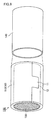
- Fig. 5 is a perspective view schematically showing an example of the exhaust gas treating body included in the exhaust gas purifying apparatus according to the first embodiment of the present invention.
- the exhaust gas treating body (honeycomb filter) 130 is mainly made of a porous ceramic material and has a substantially cylindrical shape.
- the honeycomb filter 130 is peripherally provided with a peripheral coat layer 134 so that the peripheral portion of the honeycomb filter 130 is reinforced, that the shape of the peripheral portion is arranged, and that the heat insulation of the honeycomb filter 130 is increased.
- the internal configuration of the honeycomb filter 130 is as same as that described in the description of the exhaust gas purifying apparatus according to the first embodiment of the present invention (see Fig. 4 ).
- the casing is mainly made of a metal such as stainless steel, and the shape thereof may be a substantially cylindrical shape with smaller inner diameters at both ends than the inner diameter at the center potion as shown in Fig. 4 , or a substantially cylindrical shape with a constant inner diameter.
- the inner diameter of the casing is preferably slightly smaller than the total length of the diameter of the end face of the exhaust gas treating body and the thickness of the holding sealing material (mat material) in the state of being wound around the exhaust gas treating body.
- Fig. 6 is a perspective view schematically showing an example of the method of producing the exhaust gas purifying apparatus according to the first embodiment of the present invention.
- Fig. 6 shows an example where the used casing has a substantially cylindrical shape with a constant inner diameter.
- the winding step is performed, in which the mat material 10 shown in Fig. 1 is wound around the exhaust gas treating body (honeycomb filter) 130 to provide a wound body (the exhaust gas treating body with the holding sealing material wound therearound) 150.
- the mat material 10 is wound around the substantially cylindrical exhaust gas treating body 130 produced by a conventionally known method, in such a manner that the projected portion 11 fits the recessed portion 12.
- the wound body 150 that is the exhaust gas treating body 130 with the holding sealing material 110 wound therearound is produced.
- the housing step is performed, in which the produced wound body 150 is housed in the casing 140 that has a substantially cylindrical shape of a predetermined size and is mainly made of a metal and the like.
- the casing 140 For exerting a predetermined repulsive power (i.e., power to hold the exhaust gas treating body) by compression of the holding sealing material after housing, the casing 140 has an inner diameter slightly smaller than the maximum outer diameter of the exhaust gas treating body 130 with the holding sealing material 110 wound therearound (including the thickness of the holding sealing material 110).
- the exhaust gas purifying apparatus according to the first embodiment of the present invention can be produced.
- the wound body is housed in the casing by a method such as the stuffing method, sizing (swaging) method, or clam shell method.
- a stuffing jig is used for stuffing the wound body to a predetermined position inside the casing.
- the wound body is inserted into the casing, and then the casing was compressed from the outer peripheral side in such a manner that the inner diameter of the casing is reduced.
- the casing is configured to be dividable into two parts (first casing, second casing), and the wound body is set on the first casing and sealed with the second casing placed thereon.
- the stuffing method or the sizing (swaging) method preferred is the stuffing method or the sizing (swaging) method.
- the number of production steps can be reduced because the casing is not configured by two parts.
- a urea SCR system is described as another example of the exhaust gas purifying apparatus according to the first embodiment of the present invention.
- Fig. 7 is a schematic cross-sectional view of another example of the exhaust gas purifying apparatus according to the first embodiment of the present invention.
- a urea SCR system 200 shown in Fig. 7 has a similar configuration as that of the exhaust gas purifying apparatus 100 shown in Fig. 4 , except that the urea SCR system 200 has a urea spray port 210.
- the urea spray port 210 is provided at the front section (the upstream side of the exhaust gases G) where the exhaust gases G flow into the exhaust gas treating body 130, and sprays urea water 220.
- a method of purifying exhaust gases using the urea SCR system 200 is described below with reference to Fig. 7 .
- the urea water 220 is sprayed over the exhaust gas treating body (honeycomb filter) 130. Then, urea contained in the urea water 220 is decomposed by heat of the exhaust gases to generate ammonia (not shown).
- the ammonia passes through the exhaust gas treating body 130 together with the exhaust gases G introduced in the urea SCR system 200.
- the ammonia and NO x in the exhaust gases pass through the cell walls 132 supporting a catalyst such as zeolite to be reduced into N 2 through the action of the catalyst such as zeolite. As a result, NO x is purified.
- the urea SCR system can be produced by a method similar to the method of producing the exhaust gas purifying apparatus, except that a urea spray port is provided at the front section (the upstream side of the exhaust gases G) where the exhaust gases flow into the honeycomb filter.
- glass fibers (Advantex glass manufactured by Owens Corning Japan LLC., average fiber length: 6 mm, average fiber diameter: 12 ⁇ m) were prepared.
- the glass fibers were used after heating at 740°C for 10 minutes.
- the glass fibers 134.7 g were added to water (60 L) and stirred at 60 Hz for 30 minutes.
- a latex LX852 manufactured by ZEON CORPORATION, 15.0 g was added, and the resulting mixture was stirred at 60 Hz for 1 minute.
- an alumina sol AL520 manufactured by Nissan Chemical Industries, Ltd., 5.4 g was added thereto and stirred at 60 Hz for 1 minute.
- a 0.5% by weight aqueous solution of nonionic polyacrylamide (Percol 47 manufactured by Allied Colloids) (269.3 g) was added as a polymer flocculant, and stirred at 60 Hz for 1 minute.
- a 335 mm ⁇ 335 mm TAPPI papermaking machine was used for papermaking of the slurry, thereby preparing a raw mat having a weight per unit area of 1200 g/m 2 .
- a press dryer was used for drying the raw mat in a state compressed to a thickness of 4.8 mm, at 150°C for 15 minutes, thereby producing a mat material of Example 1.
- a mat material of Comparative Example 1 was produced in the same manner as in Example 1.
- Comparative Example 1 the used glass fibers were E-glass (Owens Corning Japan LLC., average fiber length: 6 mm, average fiber diameter: 12 ⁇ m).
- the glass fibers used in Comparative Example 1 have a nominal composition of 52 to 62% by weight of SiO 2 , 12 to 16% by weight of Al 2 O 3 , 16 to 25% by weight of CaO, 0 to 5% by weight of MgO, 5 to 10% by weight of B 2 O 3 , 0 to 1.5% by weight of TiO 2 , and 0 to 2% by weight of Na 2 O and K 2 O in total.
- Example 1 the mat material of Example 1 was punched using a Thomson blade having a diameter of 50 mm to give a sample (hereafter, referred to as a sample of Example 1).
- Comparative Example 1 the mat material of Comparative Example 1 was punched to give a sample (hereafter referred to as a sample of Comparative Example 1).
- Example 1 The samples of Example 1 and Comparative Example 1 were each impregnated with 30 mL of water for 18 hours.
- Example 1 and Comparative Example 1 were each impregnated with 30 mL of a urea aqueous solution (AdBlue (registered trademark)) for 18 hours.
- AdBlue urea aqueous solution
- each sample was dried in a dryer adjusted to 105°C for 2 hours. Then, each sample was fired in an electric furnace adjusted to 400°C for 2 hours.
- the surface pressure of each sample was measured by the following method.
- the surface pressure was measured using a hot surface pressure measuring apparatus manufactured by M.T.S. Co., Ltd.
- each sample at an ambient temperature was compressed to a gap bulk density (GBD) of 0.4 g/cm 3 and maintained in that state for 5 minutes.
- GBD gap bulk density
- Gap bulk density Weight of sample/(Area of sample ⁇ Thickness of sample).
- the sample in a compressed state was heated to 500°C at a rate of 50°C/min and was released to the gap bulk density of 0.364 g/cm 3 .
- the sample was maintained at a temperature of 500°C and a gap bulk density of 0.364 g/cm 3 for 5 minutes.
- the sample was compressed to a gap bulk density of 0.4 g/cm 3 at a rate of 1 inch (25.4 mm)/min, and the load to the sample in that state was measured.
- the load was divided by the area of the sample to determine the surface pressure (kPa).
- Example 1 the sample impregnated with water had a surface pressure of 271.3 kPa and the sample impregnated with a urea aqueous solution had a surface pressure of 254.6 kPa.
- Comparative Example 1 the sample impregnated with water had a surface pressure of 306.0 kPa and the sample impregnated with a urea aqueous solution had a surface pressure of 283.1 kPa.
- Example 1 the ratio of the surface pressure of the sample impregnated with a urea aqueous solution to the sample impregnated with water was calculated to determine the reduction rate (%) of the surface pressure.
- Table 1 shows the surface pressure and the reduction rate of the surface pressure of each sample in Example 1 and Comparative Example 1.
- Fig. 8 shows a graph showing the surface pressure and the reduction rate of the surface pressure in Example 1 and Comparative Example 1.
- Table 1 Glass fiber Surface pressure [kPa] Reduction rate of surface pressure [%] Water Urea aqueous solution
- the mat material of Comparative Example 1 is used as a holding sealing material in an exhaust gas purifying apparatus, especially in a urea SCR system, the holding force of the holding sealing material is presumably significantly lowered over operating time of the apparatus.
- Example 1 In contrast, if the mat material of Example 1 is used as a holding sealing material in an exhaust gas purifying apparatus, especially in a urea SCR system, the holding force of the holding sealing material is not so much lowered over operating time of the apparatus.
- the mat material according to an embodiment of the present invention may further contain, in addition to the glass fibers described in the first embodiment of the present invention, inorganic fibers such as alumina fibers and silica fibers.
- the mat material according to an embodiment of the present invention preferably contains the glass fibers described in the first embodiment of the present invention in an amount of at least 50% by weight of the sum of all the fibers contained in the mat material. Moreover, the mat material according to an embodiment of the present invention preferably contains only the glass fibers described in the first embodiment of the present invention.
- the average fiber length of the glass fibers contained in the mat material according to an embodiment of the present invention is not particularly limited, and is preferably 30 ⁇ m to 120 mm, and more preferably 0.1 mm to 100 mm.
- the average fiber length of the glass fibers is less than 30 ⁇ m, the fiber length of the glass fibers is too short and such glass fibers are insufficiently entangled with each other. In such a case, the shear strength of the resulting mat material used as a holding sealing material is poor. If the average fiber length of the glass fibers is more than 120 mm, the fiber length of the glass fibers is too long. In such a case, the workability of the glass fibers in production of a holding sealing material is poor. Consequently, the resulting holding sealing material is difficult to be wound around the exhaust gas treating body, leading to easy cracking thereof.
- the “average fiber length of fibers” refers to the average of the lengths of 100 fibers selected randomly.
- the shapes of the recessed portion and projected portion formed at ends of the mat material according to an embodiment of the present invention are not particularly limited, as long as they fit each other.
- a set of a recessed portion and a projected portion is formed, preferably formed are a projected portion projecting in the size of 10 mm (width) ⁇ 10 mm (length) to 300 mm (width) ⁇ 100 mm (length) at a part of one end portion and a recessed portion having a shape corresponding to the projected portion at a part of the other end portion.
- the holding sealing material can surely hold an exhaust gas treating body, which means excellent handleability of the exhaust gas purifying apparatus.
- the size of the projected portion is smaller than 10 mm (width) ⁇ 10 mm (length) or larger than 300 mm (width) ⁇ 100 mm (length)
- such a mat material wound around the exhaust gas treating body has a smaller contact area between the end portions of the mat material, so that the end portions of the mat material are less likely to be attached to each other.
- the holding sealing material is less likely to hold the exhaust gas treating body.
- plural recessed portions and projected portions to be fitted to each other may be formed at the end portions of the mat material.
- no recessed portion or projected portion is formed at the end portions of the mat material.
- the "substantially rectangular shape in a plan view” mentioned in the description on the mat material according to the first embodiment of the present invention covers a concept that includes a projected portion and a recessed portion as shown in Fig. 1 .
- the "substantially rectangular shape in a plan view” includes a shape of a mat material having an edge portion with an angle of other than 90°.
- an edge portion of the mat material may have an acute or obtuse angle or a curvature.
- the weight per unit area of the mat material according to an embodiment of the present invention is not particularly limited, and is preferably 200 to 5000 g/m 2 , and more preferably 1000 to 3000 g/m 2 . If the weight per unit area of the mat material is less than 200 g/m 2 , the holding force as the holding sealing material is not enough. If the weight per unit area of the mat material is more than 5000 g/m 2 , the bulk of the mat material is less likely to be reduced. If such a mat material is used as a holding sealing material in production of an exhaust gas purifying apparatus, an exhaust gas treating body may be easily dropped from the casing.
- the gap bulk density of the mat material is not particularly limited, and is preferably 0.10 to 0.30 g/cm 3 . If the gap bulk density of the mat material is less than 0.10 g/cm 3 , the fibers are less entangled with each other. In such a case, the fibers are easily removed, so that the mat material is less likely to maintain the predetermined shape. If the gap bulk density of the mat material is more than 0.30 g/cm 3 , the mat material becomes hard. Such a mat material tends to be cracked because it is difficult to be wound around the exhaust gas treating body.
- the thickness of the mat material according to an embodiment of the present invention is not particularly limited, and is preferably 2 to 50 mm and is more preferably 6 to 20 mm.
- the thickness of the mat material is less than 2 mm, the holding force as the holding sealing material is not enough. If such a mat material is used as a holding sealing material in production of an exhaust gas purifying apparatus, an exhaust gas treating body may be easily dropped from a casing. If the thickness of the mat material is more than 50 mm, the mat material is too thick. Such a mat material is difficult to be wound around the exhaust gas treating body, leading to east cracking thereof.
- the number of holding sealing materials included in the exhaust gas purifying apparatus is not particularly limited.
- a single holding sealing material may be used, or plural holding sealing materials combined with each other may be used.
- a method of combining plural holding sealing materials is not particularly limited.
- plural holding sealing material may be sewed on a sewing machine, or bonded to each other with an adhesive tape or an adhesive agent.
- the organic binder used in production of the mat material is not limited to an acrylic resin, and may be a rubber such as acrylic rubber, a water-soluble organic polymer such as carboxymethyl cellulose or polyvinyl alcohol, a thermoplastic resin such as styrene resin, or a thermosetting resin such as epoxy resin.
- acrylic rubber acrylonitrile-polybutadiene rubber, and styrene-polybutadiene rubber.
- the emulsion (binder solution) used in production of the mat material may contain plural kinds of organic binders mentioned above.
- binder solution examples include, in addition to an above-mentioned latex containing an organic binder dispersed in water, a solution containing an above-mentioned organic binder dissolved in water or an organic solvent.
- the emulsion (binder solution) used in production of the mat material may further contain an inorganic binder.
- the binder solution contains an inorganic binder
- examples of the inorganic binder include an alumina sol and a silica sol.
- the material of the casing included in the exhaust gas purifying apparatus according to an embodiment of the present invention is not particularly limited as long as it is a heat-resistant metal. Specific examples thereof include metals such as stainless steel, aluminum, and iron.
- Preferable examples of the shape of the casing included in the exhaust gas purifying apparatus according to an embodiment of the present invention include, in addition to the substantially cylindrical shape, shapes of clamshell-type and downsizing-type.
- the shape of the exhaust gas treating body included in the exhaust gas purifying apparatus according to an embodiment of the present invention is not particularly limited, as long as it is a pillar shape.
- the exhaust gas treating body may have any shape in any size, other than the substantially cylindrical shape, such as a substantially elliptic cylinder shape and a substantially rectangular column shape.
- the exhaust gas treating body included in the exhaust gas purifying apparatus may be an integral honeycomb structured body that is integrally formed of cordierite or the like as shown in Fig. 5 or an aggregated honeycomb structured body including plural cylindrical honeycomb fired bodies made of silicon carbide or the like, wherein the plural cylindrical honeycomb fired bodies are bonded to each other via an adhesive layer mainly containing a ceramic material and each include a large number of through holes disposed in parallel in the longitudinal direction with partition walls therebetween.
- the exhaust gas treating body included in the exhaust gas purifying apparatus may support a catalyst.
- Examples of the catalyst supported on the exhaust gas treating body include: noble metals such as platinum, palladium, and rhodium; alkaline metals such as potassium and sodium; alkaline earth metals such as barium; and metal oxides such as cerium oxide. Each of these catalysts may be used alone, or two or more of these may be used in combination.
- the exhaust gas treating body is a honeycomb structured body, cells therein may have the end portions not sealed with plugs.
- the exhaust gas treating body functions as a catalyst supporting carrier that supports a catalyst such as platinum and purifies harmful gas components such as CO, HC, and NO x contained in exhaust gases.
- the mat material of the present invention it is essential that the mat material contains glass fibers, the glass fibers containing 52 to 66% by weight of SiO 2 , 9 to 26% by weight of Al 2 O 3 , 15 to 27% by weight of CaO, 0 to 9% by weight of MgO, 0 to 4% by weight of TiO 2 , 0 to 5% by weight of ZnO, and 0 to 2% by weight of Na 2 O and K 2 O in total and being substantially free of B 2 O 3 .
- the mat material of the present invention is used as a holding sealing material.
- Desired effects can be obtained by appropriately combining such essential features with various features (e.g., composition of glass fibers, shape of mat material, method of producing mat material) described in the first embodiment and other embodiments of the present invention.
Applications Claiming Priority (2)
| Application Number | Priority Date | Filing Date | Title |
|---|---|---|---|
| JP2011231971A JP5872841B2 (ja) | 2011-10-21 | 2011-10-21 | マット材及び排ガス浄化装置 |
| PCT/JP2012/075607 WO2013058108A1 (fr) | 2011-10-21 | 2012-10-03 | Matériau pour nappes et dispositif de purification de gaz d'échappement |
Publications (3)
| Publication Number | Publication Date |
|---|---|
| EP2770179A1 true EP2770179A1 (fr) | 2014-08-27 |
| EP2770179A4 EP2770179A4 (fr) | 2015-07-15 |
| EP2770179B1 EP2770179B1 (fr) | 2017-06-21 |
Family
ID=48140760
Family Applications (1)
| Application Number | Title | Priority Date | Filing Date |
|---|---|---|---|
| EP12842344.9A Active EP2770179B1 (fr) | 2011-10-21 | 2012-10-03 | Matériau pour nappes et dispositif de purification de gaz d'échappement |
Country Status (6)
| Country | Link |
|---|---|
| US (1) | US20140227143A1 (fr) |
| EP (1) | EP2770179B1 (fr) |
| JP (1) | JP5872841B2 (fr) |
| CN (1) | CN103890339A (fr) |
| IN (1) | IN2014CN03153A (fr) |
| WO (1) | WO2013058108A1 (fr) |
Families Citing this family (4)
| Publication number | Priority date | Publication date | Assignee | Title |
|---|---|---|---|---|
| JP2015090114A (ja) * | 2013-11-06 | 2015-05-11 | イビデン株式会社 | 保持シール材、巻付体及び排ガス浄化装置 |
| JP6486328B2 (ja) * | 2016-12-26 | 2019-03-20 | ニチアス株式会社 | 排気ガス処理装置用保持材および排気ガス処理装置 |
| JP7258457B2 (ja) | 2017-08-25 | 2023-04-17 | デンカ株式会社 | アルミナ繊維、アルミナ繊維集合体及び排ガス浄化装置用把持材 |
| US10220376B1 (en) * | 2017-12-05 | 2019-03-05 | James G. Davidson | Catalytic composition and system for exhaust purification |
Family Cites Families (10)
| Publication number | Priority date | Publication date | Assignee | Title |
|---|---|---|---|---|
| JP3584966B2 (ja) * | 2000-01-21 | 2004-11-04 | 日東紡績株式会社 | 耐熱性ガラス繊維及びその製造方法 |
| EP1337486A4 (fr) * | 2000-09-06 | 2008-11-05 | Ppg Ind Ohio Inc | Compositions de formation de fibres de verre |
| ATE419456T1 (de) * | 2002-07-31 | 2009-01-15 | 3M Innovative Properties Co | Matte für die lagerung einer monolithen reinigungsvorrichtung in einer abgasreinigungsvorrichtung für die behandlung von abgasen einer dieselbrennkraftmaschine |
| US7550118B2 (en) * | 2004-04-14 | 2009-06-23 | 3M Innovative Properties Company | Multilayer mats for use in pollution control devices |
| JP4656533B2 (ja) * | 2007-02-20 | 2011-03-23 | 株式会社三五 | ハニカム構造体内蔵流体処理装置の製造方法 |
| CN101678347B (zh) * | 2008-05-20 | 2012-10-03 | 揖斐电株式会社 | 蜂窝结构体以及废气净化装置 |
| JP2011026755A (ja) * | 2009-07-01 | 2011-02-10 | Ibiden Co Ltd | マット材および排気ガス処理装置 |
| JP2011125847A (ja) * | 2009-11-19 | 2011-06-30 | Ibiden Co Ltd | ハニカム構造体およびハニカム構造体の製造方法 |
| KR101796329B1 (ko) * | 2009-12-17 | 2017-11-09 | 유니프랙스 아이 엘엘씨 | 배기 가스 처리 기기용 장착 매트 |
| EP2753590B1 (fr) * | 2011-09-09 | 2024-02-14 | Electric Glass Fiber America, LLC | Compositions de verre et fibres obtenues à partir de celles-ci |
-
2011
- 2011-10-21 JP JP2011231971A patent/JP5872841B2/ja active Active
-
2012
- 2012-10-03 CN CN201280051377.9A patent/CN103890339A/zh active Pending
- 2012-10-03 WO PCT/JP2012/075607 patent/WO2013058108A1/fr active Application Filing
- 2012-10-03 EP EP12842344.9A patent/EP2770179B1/fr active Active
-
2014
- 2014-04-16 US US14/254,790 patent/US20140227143A1/en not_active Abandoned
- 2014-04-25 IN IN3153CHN2014 patent/IN2014CN03153A/en unknown
Also Published As
| Publication number | Publication date |
|---|---|
| WO2013058108A1 (fr) | 2013-04-25 |
| JP5872841B2 (ja) | 2016-03-01 |
| CN103890339A (zh) | 2014-06-25 |
| IN2014CN03153A (fr) | 2015-07-03 |
| JP2013087756A (ja) | 2013-05-13 |
| EP2770179A4 (fr) | 2015-07-15 |
| US20140227143A1 (en) | 2014-08-14 |
| EP2770179B1 (fr) | 2017-06-21 |
Similar Documents
| Publication | Publication Date | Title |
|---|---|---|
| EP2594758B1 (fr) | Matériau de fixation et d'étanchement, procédé de fabrication de ce matériau et appareil de purification de gaz d'échappement | |
| JP4959206B2 (ja) | 耐熱シートおよび排気ガス浄化装置 | |
| KR101047623B1 (ko) | 생체가용성 무기 섬유 및 운모질 결합제를 함유하는 조성물 | |
| EP2119886B1 (fr) | Matériau de scellage de fixation, procédé de fabrication du matériau de scellage de fixation et appareil de purification de gaz d'échappement | |
| US9816420B2 (en) | Mounting mat for exhaust gas treatment device | |
| US8765069B2 (en) | Exhaust gas treatment device | |
| JP2018048647A (ja) | 汚染物質制御デバイス用の多層装着マット | |
| KR101749217B1 (ko) | 유지 시일재, 유지 시일재의 제조 방법 및 배기 가스 정화 장치 | |
| US8444753B2 (en) | Exhaust gas purifying system, method for manufacturing the exhaust gas purifying system and exhaust gas purifying method using the exhaust gas purifying system | |
| EP2770179B1 (fr) | Matériau pour nappes et dispositif de purification de gaz d'échappement | |
| KR20090109471A (ko) | 유지 시일재 및 배기 가스 정화 장치 | |
| EP2386739B1 (fr) | Mat, son procédé de fabrication et un appareil de purification de gaz d'échappement le contenant | |
| EP3051187B1 (fr) | Matériau de joint d'étanchéité de support, procédé de production pour matériau de joint d'étanchéité de support, procédé de production pour dispositif de purification de gaz d'échappement et dispositif de purification de gaz d'échappement | |
| JP2013170338A (ja) | マット材、マット材の製造方法、及び、排ガス浄化装置 | |
| JP2022064727A (ja) | 無機シート材付き無機繊維集合体、無機シート材付き無機繊維集合体の製造方法及び排ガス浄化装置 | |
| JP2023048673A (ja) | 保持シール材、保持シール材の製造方法及び排ガス浄化装置 |
Legal Events
| Date | Code | Title | Description |
|---|---|---|---|
| PUAI | Public reference made under article 153(3) epc to a published international application that has entered the european phase |
Free format text: ORIGINAL CODE: 0009012 |
|
| 17P | Request for examination filed |
Effective date: 20140414 |
|
| AK | Designated contracting states |
Kind code of ref document: A1 Designated state(s): AL AT BE BG CH CY CZ DE DK EE ES FI FR GB GR HR HU IE IS IT LI LT LU LV MC MK MT NL NO PL PT RO RS SE SI SK SM TR |
|
| DAX | Request for extension of the european patent (deleted) | ||
| RIC1 | Information provided on ipc code assigned before grant |
Ipc: D04H 1/4218 20120101ALI20150529BHEP Ipc: B01D 53/94 20060101ALI20150529BHEP Ipc: F01N 3/022 20060101ALI20150529BHEP Ipc: F01N 3/28 20060101AFI20150529BHEP |
|
| RA4 | Supplementary search report drawn up and despatched (corrected) |
Effective date: 20150616 |
|
| RIC1 | Information provided on ipc code assigned before grant |
Ipc: F01N 3/28 20060101AFI20150610BHEP Ipc: F01N 3/022 20060101ALI20150610BHEP Ipc: D04H 1/4218 20120101ALI20150610BHEP Ipc: B01D 53/94 20060101ALI20150610BHEP |
|
| 17Q | First examination report despatched |
Effective date: 20160302 |
|
| GRAP | Despatch of communication of intention to grant a patent |
Free format text: ORIGINAL CODE: EPIDOSNIGR1 |
|
| INTG | Intention to grant announced |
Effective date: 20170216 |
|
| GRAS | Grant fee paid |
Free format text: ORIGINAL CODE: EPIDOSNIGR3 |
|
| GRAA | (expected) grant |
Free format text: ORIGINAL CODE: 0009210 |
|
| AK | Designated contracting states |
Kind code of ref document: B1 Designated state(s): AL AT BE BG CH CY CZ DE DK EE ES FI FR GB GR HR HU IE IS IT LI LT LU LV MC MK MT NL NO PL PT RO RS SE SI SK SM TR |
|
| REG | Reference to a national code |
Ref country code: GB Ref legal event code: FG4D |
|
| RIN1 | Information on inventor provided before grant (corrected) |
Inventor name: NISHI AKIHITO |
|
| REG | Reference to a national code |
Ref country code: CH Ref legal event code: EP |
|
| REG | Reference to a national code |
Ref country code: IE Ref legal event code: FG4D |
|
| REG | Reference to a national code |
Ref country code: AT Ref legal event code: REF Ref document number: 903152 Country of ref document: AT Kind code of ref document: T Effective date: 20170715 |
|
| REG | Reference to a national code |
Ref country code: DE Ref legal event code: R096 Ref document number: 602012033808 Country of ref document: DE |
|
| RAP2 | Party data changed (patent owner data changed or rights of a patent transferred) |
Owner name: IBIDEN CO., LTD. |
|
| REG | Reference to a national code |
Ref country code: NL Ref legal event code: MP Effective date: 20170621 |
|
| PG25 | Lapsed in a contracting state [announced via postgrant information from national office to epo] |
Ref country code: HR Free format text: LAPSE BECAUSE OF FAILURE TO SUBMIT A TRANSLATION OF THE DESCRIPTION OR TO PAY THE FEE WITHIN THE PRESCRIBED TIME-LIMIT Effective date: 20170621 Ref country code: GR Free format text: LAPSE BECAUSE OF FAILURE TO SUBMIT A TRANSLATION OF THE DESCRIPTION OR TO PAY THE FEE WITHIN THE PRESCRIBED TIME-LIMIT Effective date: 20170922 Ref country code: LT Free format text: LAPSE BECAUSE OF FAILURE TO SUBMIT A TRANSLATION OF THE DESCRIPTION OR TO PAY THE FEE WITHIN THE PRESCRIBED TIME-LIMIT Effective date: 20170621 Ref country code: FI Free format text: LAPSE BECAUSE OF FAILURE TO SUBMIT A TRANSLATION OF THE DESCRIPTION OR TO PAY THE FEE WITHIN THE PRESCRIBED TIME-LIMIT Effective date: 20170621 Ref country code: NO Free format text: LAPSE BECAUSE OF FAILURE TO SUBMIT A TRANSLATION OF THE DESCRIPTION OR TO PAY THE FEE WITHIN THE PRESCRIBED TIME-LIMIT Effective date: 20170921 |
|
| REG | Reference to a national code |
Ref country code: LT Ref legal event code: MG4D |
|
| REG | Reference to a national code |
Ref country code: AT Ref legal event code: MK05 Ref document number: 903152 Country of ref document: AT Kind code of ref document: T Effective date: 20170621 |
|
| PG25 | Lapsed in a contracting state [announced via postgrant information from national office to epo] |
Ref country code: NL Free format text: LAPSE BECAUSE OF FAILURE TO SUBMIT A TRANSLATION OF THE DESCRIPTION OR TO PAY THE FEE WITHIN THE PRESCRIBED TIME-LIMIT Effective date: 20170621 Ref country code: SE Free format text: LAPSE BECAUSE OF FAILURE TO SUBMIT A TRANSLATION OF THE DESCRIPTION OR TO PAY THE FEE WITHIN THE PRESCRIBED TIME-LIMIT Effective date: 20170621 Ref country code: BG Free format text: LAPSE BECAUSE OF FAILURE TO SUBMIT A TRANSLATION OF THE DESCRIPTION OR TO PAY THE FEE WITHIN THE PRESCRIBED TIME-LIMIT Effective date: 20170921 Ref country code: RS Free format text: LAPSE BECAUSE OF FAILURE TO SUBMIT A TRANSLATION OF THE DESCRIPTION OR TO PAY THE FEE WITHIN THE PRESCRIBED TIME-LIMIT Effective date: 20170621 Ref country code: LV Free format text: LAPSE BECAUSE OF FAILURE TO SUBMIT A TRANSLATION OF THE DESCRIPTION OR TO PAY THE FEE WITHIN THE PRESCRIBED TIME-LIMIT Effective date: 20170621 |
|
| PG25 | Lapsed in a contracting state [announced via postgrant information from national office to epo] |
Ref country code: SK Free format text: LAPSE BECAUSE OF FAILURE TO SUBMIT A TRANSLATION OF THE DESCRIPTION OR TO PAY THE FEE WITHIN THE PRESCRIBED TIME-LIMIT Effective date: 20170621 Ref country code: EE Free format text: LAPSE BECAUSE OF FAILURE TO SUBMIT A TRANSLATION OF THE DESCRIPTION OR TO PAY THE FEE WITHIN THE PRESCRIBED TIME-LIMIT Effective date: 20170621 Ref country code: CZ Free format text: LAPSE BECAUSE OF FAILURE TO SUBMIT A TRANSLATION OF THE DESCRIPTION OR TO PAY THE FEE WITHIN THE PRESCRIBED TIME-LIMIT Effective date: 20170621 Ref country code: RO Free format text: LAPSE BECAUSE OF FAILURE TO SUBMIT A TRANSLATION OF THE DESCRIPTION OR TO PAY THE FEE WITHIN THE PRESCRIBED TIME-LIMIT Effective date: 20170621 Ref country code: AT Free format text: LAPSE BECAUSE OF FAILURE TO SUBMIT A TRANSLATION OF THE DESCRIPTION OR TO PAY THE FEE WITHIN THE PRESCRIBED TIME-LIMIT Effective date: 20170621 |
|
| PG25 | Lapsed in a contracting state [announced via postgrant information from national office to epo] |
Ref country code: PL Free format text: LAPSE BECAUSE OF FAILURE TO SUBMIT A TRANSLATION OF THE DESCRIPTION OR TO PAY THE FEE WITHIN THE PRESCRIBED TIME-LIMIT Effective date: 20170621 Ref country code: ES Free format text: LAPSE BECAUSE OF FAILURE TO SUBMIT A TRANSLATION OF THE DESCRIPTION OR TO PAY THE FEE WITHIN THE PRESCRIBED TIME-LIMIT Effective date: 20170621 Ref country code: IS Free format text: LAPSE BECAUSE OF FAILURE TO SUBMIT A TRANSLATION OF THE DESCRIPTION OR TO PAY THE FEE WITHIN THE PRESCRIBED TIME-LIMIT Effective date: 20171021 Ref country code: IT Free format text: LAPSE BECAUSE OF FAILURE TO SUBMIT A TRANSLATION OF THE DESCRIPTION OR TO PAY THE FEE WITHIN THE PRESCRIBED TIME-LIMIT Effective date: 20170621 Ref country code: SM Free format text: LAPSE BECAUSE OF FAILURE TO SUBMIT A TRANSLATION OF THE DESCRIPTION OR TO PAY THE FEE WITHIN THE PRESCRIBED TIME-LIMIT Effective date: 20170621 |
|
| REG | Reference to a national code |
Ref country code: DE Ref legal event code: R097 Ref document number: 602012033808 Country of ref document: DE |
|
| PLBE | No opposition filed within time limit |
Free format text: ORIGINAL CODE: 0009261 |
|
| STAA | Information on the status of an ep patent application or granted ep patent |
Free format text: STATUS: NO OPPOSITION FILED WITHIN TIME LIMIT |
|
| PG25 | Lapsed in a contracting state [announced via postgrant information from national office to epo] |
Ref country code: DK Free format text: LAPSE BECAUSE OF FAILURE TO SUBMIT A TRANSLATION OF THE DESCRIPTION OR TO PAY THE FEE WITHIN THE PRESCRIBED TIME-LIMIT Effective date: 20170621 |
|
| 26N | No opposition filed |
Effective date: 20180322 |
|
| PG25 | Lapsed in a contracting state [announced via postgrant information from national office to epo] |
Ref country code: MC Free format text: LAPSE BECAUSE OF FAILURE TO SUBMIT A TRANSLATION OF THE DESCRIPTION OR TO PAY THE FEE WITHIN THE PRESCRIBED TIME-LIMIT Effective date: 20170621 |
|
| REG | Reference to a national code |
Ref country code: CH Ref legal event code: PL |
|
| GBPC | Gb: european patent ceased through non-payment of renewal fee |
Effective date: 20171003 |
|
| REG | Reference to a national code |
Ref country code: IE Ref legal event code: MM4A |
|
| REG | Reference to a national code |
Ref country code: FR Ref legal event code: ST Effective date: 20180629 |
|
| PG25 | Lapsed in a contracting state [announced via postgrant information from national office to epo] |
Ref country code: LU Free format text: LAPSE BECAUSE OF NON-PAYMENT OF DUE FEES Effective date: 20171003 Ref country code: GB Free format text: LAPSE BECAUSE OF NON-PAYMENT OF DUE FEES Effective date: 20171003 Ref country code: CH Free format text: LAPSE BECAUSE OF NON-PAYMENT OF DUE FEES Effective date: 20171031 Ref country code: LI Free format text: LAPSE BECAUSE OF NON-PAYMENT OF DUE FEES Effective date: 20171031 |
|
| REG | Reference to a national code |
Ref country code: BE Ref legal event code: MM Effective date: 20171031 |
|
| PG25 | Lapsed in a contracting state [announced via postgrant information from national office to epo] |
Ref country code: FR Free format text: LAPSE BECAUSE OF NON-PAYMENT OF DUE FEES Effective date: 20171031 Ref country code: BE Free format text: LAPSE BECAUSE OF NON-PAYMENT OF DUE FEES Effective date: 20171031 Ref country code: SI Free format text: LAPSE BECAUSE OF FAILURE TO SUBMIT A TRANSLATION OF THE DESCRIPTION OR TO PAY THE FEE WITHIN THE PRESCRIBED TIME-LIMIT Effective date: 20170621 |
|
| PG25 | Lapsed in a contracting state [announced via postgrant information from national office to epo] |
Ref country code: MT Free format text: LAPSE BECAUSE OF NON-PAYMENT OF DUE FEES Effective date: 20171003 |
|
| PG25 | Lapsed in a contracting state [announced via postgrant information from national office to epo] |
Ref country code: IE Free format text: LAPSE BECAUSE OF NON-PAYMENT OF DUE FEES Effective date: 20171003 |
|
| PG25 | Lapsed in a contracting state [announced via postgrant information from national office to epo] |
Ref country code: HU Free format text: LAPSE BECAUSE OF FAILURE TO SUBMIT A TRANSLATION OF THE DESCRIPTION OR TO PAY THE FEE WITHIN THE PRESCRIBED TIME-LIMIT; INVALID AB INITIO Effective date: 20121003 |
|
| PG25 | Lapsed in a contracting state [announced via postgrant information from national office to epo] |
Ref country code: CY Free format text: LAPSE BECAUSE OF NON-PAYMENT OF DUE FEES Effective date: 20170621 |
|
| PG25 | Lapsed in a contracting state [announced via postgrant information from national office to epo] |
Ref country code: MK Free format text: LAPSE BECAUSE OF FAILURE TO SUBMIT A TRANSLATION OF THE DESCRIPTION OR TO PAY THE FEE WITHIN THE PRESCRIBED TIME-LIMIT Effective date: 20170621 |
|
| PG25 | Lapsed in a contracting state [announced via postgrant information from national office to epo] |
Ref country code: TR Free format text: LAPSE BECAUSE OF FAILURE TO SUBMIT A TRANSLATION OF THE DESCRIPTION OR TO PAY THE FEE WITHIN THE PRESCRIBED TIME-LIMIT Effective date: 20170621 |
|
| PG25 | Lapsed in a contracting state [announced via postgrant information from national office to epo] |
Ref country code: PT Free format text: LAPSE BECAUSE OF FAILURE TO SUBMIT A TRANSLATION OF THE DESCRIPTION OR TO PAY THE FEE WITHIN THE PRESCRIBED TIME-LIMIT Effective date: 20170621 |
|
| PG25 | Lapsed in a contracting state [announced via postgrant information from national office to epo] |
Ref country code: AL Free format text: LAPSE BECAUSE OF FAILURE TO SUBMIT A TRANSLATION OF THE DESCRIPTION OR TO PAY THE FEE WITHIN THE PRESCRIBED TIME-LIMIT Effective date: 20170621 |
|
| PGFP | Annual fee paid to national office [announced via postgrant information from national office to epo] |
Ref country code: DE Payment date: 20230830 Year of fee payment: 12 |