EP2769903A1 - Battery layout structure of saddle-ride type vehicle - Google Patents
Battery layout structure of saddle-ride type vehicle Download PDFInfo
- Publication number
- EP2769903A1 EP2769903A1 EP14155324.8A EP14155324A EP2769903A1 EP 2769903 A1 EP2769903 A1 EP 2769903A1 EP 14155324 A EP14155324 A EP 14155324A EP 2769903 A1 EP2769903 A1 EP 2769903A1
- Authority
- EP
- European Patent Office
- Prior art keywords
- battery
- stay
- saddle
- head pipe
- layout structure
- Prior art date
- Legal status (The legal status is an assumption and is not a legal conclusion. Google has not performed a legal analysis and makes no representation as to the accuracy of the status listed.)
- Granted
Links
Images





Classifications
-
- B—PERFORMING OPERATIONS; TRANSPORTING
- B62—LAND VEHICLES FOR TRAVELLING OTHERWISE THAN ON RAILS
- B62K—CYCLES; CYCLE FRAMES; CYCLE STEERING DEVICES; RIDER-OPERATED TERMINAL CONTROLS SPECIALLY ADAPTED FOR CYCLES; CYCLE AXLE SUSPENSIONS; CYCLE SIDECARS, FORECARS, OR THE LIKE
- B62K19/00—Cycle frames
- B62K19/30—Frame parts shaped to receive other cycle parts or accessories
-
- B—PERFORMING OPERATIONS; TRANSPORTING
- B60—VEHICLES IN GENERAL
- B60L—PROPULSION OF ELECTRICALLY-PROPELLED VEHICLES; SUPPLYING ELECTRIC POWER FOR AUXILIARY EQUIPMENT OF ELECTRICALLY-PROPELLED VEHICLES; ELECTRODYNAMIC BRAKE SYSTEMS FOR VEHICLES IN GENERAL; MAGNETIC SUSPENSION OR LEVITATION FOR VEHICLES; MONITORING OPERATING VARIABLES OF ELECTRICALLY-PROPELLED VEHICLES; ELECTRIC SAFETY DEVICES FOR ELECTRICALLY-PROPELLED VEHICLES
- B60L50/00—Electric propulsion with power supplied within the vehicle
- B60L50/50—Electric propulsion with power supplied within the vehicle using propulsion power supplied by batteries or fuel cells
- B60L50/60—Electric propulsion with power supplied within the vehicle using propulsion power supplied by batteries or fuel cells using power supplied by batteries
- B60L50/66—Arrangements of batteries
-
- B—PERFORMING OPERATIONS; TRANSPORTING
- B60—VEHICLES IN GENERAL
- B60R—VEHICLES, VEHICLE FITTINGS, OR VEHICLE PARTS, NOT OTHERWISE PROVIDED FOR
- B60R16/00—Electric or fluid circuits specially adapted for vehicles and not otherwise provided for; Arrangement of elements of electric or fluid circuits specially adapted for vehicles and not otherwise provided for
- B60R16/02—Electric or fluid circuits specially adapted for vehicles and not otherwise provided for; Arrangement of elements of electric or fluid circuits specially adapted for vehicles and not otherwise provided for electric constitutive elements
- B60R16/04—Arrangement of batteries
-
- B—PERFORMING OPERATIONS; TRANSPORTING
- B62—LAND VEHICLES FOR TRAVELLING OTHERWISE THAN ON RAILS
- B62K—CYCLES; CYCLE FRAMES; CYCLE STEERING DEVICES; RIDER-OPERATED TERMINAL CONTROLS SPECIALLY ADAPTED FOR CYCLES; CYCLE AXLE SUSPENSIONS; CYCLE SIDECARS, FORECARS, OR THE LIKE
- B62K19/00—Cycle frames
- B62K19/30—Frame parts shaped to receive other cycle parts or accessories
- B62K19/40—Frame parts shaped to receive other cycle parts or accessories for attaching accessories, e.g. article carriers, lamps
-
- Y—GENERAL TAGGING OF NEW TECHNOLOGICAL DEVELOPMENTS; GENERAL TAGGING OF CROSS-SECTIONAL TECHNOLOGIES SPANNING OVER SEVERAL SECTIONS OF THE IPC; TECHNICAL SUBJECTS COVERED BY FORMER USPC CROSS-REFERENCE ART COLLECTIONS [XRACs] AND DIGESTS
- Y02—TECHNOLOGIES OR APPLICATIONS FOR MITIGATION OR ADAPTATION AGAINST CLIMATE CHANGE
- Y02T—CLIMATE CHANGE MITIGATION TECHNOLOGIES RELATED TO TRANSPORTATION
- Y02T10/00—Road transport of goods or passengers
- Y02T10/60—Other road transportation technologies with climate change mitigation effect
- Y02T10/70—Energy storage systems for electromobility, e.g. batteries
Definitions
- the present invention relates to battery layout structure of a saddle-ride type vehicle.
- a saddle-ride type vehicle where a battery is provided in front of a head pipe inside a front cover that covers the head pipe and a terminal of the battery is arranged on a top face of the battery is known (for example, refer to a patent literature 1).
- the present invention is made in view of the above-mentioned situation and an object of the present invention is to enable effectively utilizing space on the upside of a battery in battery layout structure of a saddle-ride type vehicle.
- the present invention is based upon battery layout structure of a saddle-ride type vehicle provided with a head pipe (12) that forms the front of a body frame (11) and steerably journals a front wheel (33), a fore cover (60) that covers a circumference of the head pipe (12) and a battery (88) provided in front of the head pipe (12) and inside the fore cover (60), and has a characteristic that the battery (88) is arranged so that battery terminals (91a, 91b) face forward.
- the battery is arranged so that the battery terminals provided in front of the head pipe and inside the fore cover face forward and the battery terminals are attached/detached from the front side, configuration space on the upside of the battery is not restricted by the detachability of the battery terminals. Therefore, the space on the upside of the battery can be effectively utilized.
- the present invention has a characteristic that the battery (88) is formed in a rectangular parallelopiped so that a bottom face (88a) has the largest area and a battery stay (85) which is provided to the head pipe (12) and which supports the bottom face (88a) and the bottom face (88a) of the battery (88) are formed in substantial parallel.
- the bottom face having the largest area of the battery can be supported by the battery stay and rigidity for supporting the battery can be increased.
- the present invention has a characteristic that the battery terminals (91a, 91b) are formed in an upper part of the battery (88).
- the workability for detaching of the battery terminal is satisfactory.
- the present invention has a characteristic that the battery (88) is supported by a battery surrounding stay (86) that covers a circumference of the battery (88) and a lamp (74) is fixed to the battery surrounding stay (86).
- a degree of freedom in a shape of the battery surrounding stay can be enhanced utilizing the configuration space secured on the upside of the battery and the lamp can be fixed to the battery surrounding stay. Therefore, a stay and others dedicated to the lamp are not required and the number of parts can be reduced.
- the fuse box can be also easily maintained in accordance with the maintenance of the battery.
- the present invention has a characteristic that a brake hose (127c) and a seat locking cable (128b) for opening/closing a seat (46) for an occupant are arranged on the upside of the battery (88).
- the brake hose and the seat locking cable can be reduced.
- the space on the upside of the battery can be effectively utilized.
- the protruded wall obstructs when the insertion in the reverse direction of the battery is tried, the wrong assembly of the battery can be prevented with the simple configuration.
- a direction such as a longitudinal direction, a lateral direction and a vertical direction shall be the same as a direction in a vehicle body unless otherwise provided.
- a reference sign FR in each drawing denotes the front side of the vehicle body
- UP denotes the upside of the vehicle body
- LE denotes the left side of the vehicle body.
- Fig. 1 is a left side view showing a motorcycle 10 provided with battery layout structure equivalent to the embodiment of the present invention.
- the motorcycle 10 is a scooter-type saddle-ride type vehicle provided with a low deck floor step 57 for an occupant seated on a seat 46 to put his/her feet, a front wheel 33 is provided in front of a body frame 11, and a rear wheel 43 which is a driving wheel is journaled to a unit swing type power unit 21 coupled to the rear of the body frame 11.
- the body frame 11 is provided with the head pipe 12, a down frame 14 extended downward and diagonally backward from the head pipe 12, a pair of right and left lower frames 16
- Each rear frame 17 is provided with the front part 17a of the rear frame extended backward on the downside of the seat 46 with the rear higher and the rear part 17b of the rear frame extended backward and upward at a gentler inclination than the front part 17a of the rear frame.
- the housing box 22 is covered with the center cover 61 from the front side and the sides of the housing box are covered with the fronts of the right and left body side covers 62.
- the sides of the fuel tank 27 are covered with the rears of the right and left body side covers 62.
- the seat 46 is integrally provided with a front seat 46a for a rider to be seated and a rear seat 46b for a pillion passenger formed to be higher than the front seat 46a by one step.
- a folding type step 28 for an occupant for the pillion passenger seated on the rear seat 46b to put his/her foot is provided at a lower end of the body lower cover 64.
- the front of the rear wheel 43 is covered with a rear fender on the front side 29 from the upside.
- a headlight 71 is provided to the front
- a windshield 72 is provided to an upper part
- a pair of right and left rearview mirrors 73 (only the rearview mirror 73 on this side is shown) is provided to right and left ends.
- a folding type side kickstand 75 is provided to the left lower frame 16 and a main kickstand 76 is provided on the downside of the crankcase 37.
- a blinker 74 (a lamp) is integrated with the front cover 51.
- a grab rail 77 for the pillion passenger to grab is provided at the back of the seat 46 and a luggage box 78 is attached to the rear of the grab rail 77.
- the rear wheel 43 is covered with a rear fender 79 from the upside and a license plate is provided to the rear fender 79.
- a tail lamp 69 is provided at the back of the rear side cover 66.
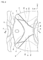
- Fig. 2 is a front view showing the front of the vehicle viewed from the front side.
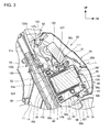
- Fig. 3 is a sectional view taken along line III-III in Fig. 2 .
- the front cover 51 is a curved cover the center in a direction of vehicle width of which is protruded forward.
- the front cover 51 is provided with a front cover part 80 that covers the head pipe 12 from the front side, a front upper cover part 81 which connects with an upper edge of the front cover part 80 and which covers the handlebar stem 31a from the front side, a pair of right and left side cover parts 82 which are extended backward and downward from right and left edges of the front cover part 80 and which cover the front side of the down frame 14 from each side and the pair of right and left blinkers 74 coupled to right and left edges of the front cover part 80 and the front upper cover part 81.
- the fore cover 60 that covers the head pipe 12 from a circumference is provided with the front cover 51, the leg shield 56 coupled to a peripheral edge of the front cover 51 and located on the rear side of the head pipe 12 and the front inner cover 54.
- the front cover part 80 is provided with the center 80a that covers a lower part of the head pipe 12 from the front side and extended parts 80b extended diagonally upward from the center 80a to the sides of right and left shoulders of the front cover 51 in a front view, and an upper edge 80c of the front cover part 80 is formed in a curve the center of which is protruded downward.
- the front upper cover part 81 is a substantially triangular cover in a front view having a lower edge along the upper edge 80c and protruded downward and is located on the downside of the headlight 71.
- Each side cover part 82 is provided with an upper edge part 82a extended to the sides of the right and left shoulders of the front cover 51 diagonally upward along a lower edge of the extended part 80b, is extended downward from the upper edge part 82a, and is coupled to a front end of the front lower cover 52 through the side of the head pipe 12.
- Right and left ends of the extended parts 80b are located inside right and left ends of the front upper cover part 81 and right and left ends of the upper edges 82a of the side cover parts 82 and space is formed in the right and left shoulders of the front cover 51.
- the blinkers 74 are embedded in the space and are integrated with the front cover 51.
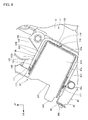
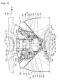
- Fig. 4 is a front view showing structure inside the fore cover 60. In Fig. 4 , a state in which the front cover 51 is removed is shown.
- a battery stay 85 extended forward from the head pipe 12 is provided to a front face of the head pipe 12 inside the fore cover 60 and a cage type battery surrounding stay 86 is supported by a top face of the battery stay 85.
- a resin battery box 87 is arranged in the battery surrounding stay 86 and a battery 88 that supplies power to an electric system of the vehicle is supported by the battery stay 85 in a state in which the battery is housed in the battery box 87.
- the battery stay 85 and the battery surrounding stay 86 are integrated and configure a battery support 100 that supports the battery 88.
- the battery 88 is formed to be longer in the width, and the bottom face 88a and the top face 88b out of the six outside faces have the large area.
- the part 96 extended in the direction of vehicle width is provided with a horizontal part 96a which pierces the side of an intermediate part in a longitudinal direction of the stay main body 95 and a bent part 96b bent from a right end of the horizontal part 96a and extended to the side of the head pipe 12 with the rear lower, and a platelike electric equipment stay 96c is provided to a rear end of the bent part 96b. Both ends of the horizontal part 96a are located on the downsides of right and left ends of the battery surrounding stay 86.
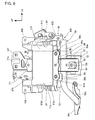
- the battery surrounding stay 86 is provided with a frame part 101 acquired by forming a band plate to be a rectangular frame in a front view (see Fig. 6 ), a vertically coupling plate 102 acquired by forming a band plate in a U shape open forward in a side view (see Fig. 5 ) and a laterally coupling plate 103 acquired by forming a band plate in a U shape open forward in a top view (see Fig. 7 ).
- a reinforcing plate 99 coupled to the horizontal part 96a of the part 96 extended in the direction of vehicle width is provided to the bottom face of the frame part 101 on the side close to the bent part 96b.
- the frame part 101 can be reinforced with the reinforcing plate 99, rigidity for supporting the battery 88 is increased.
- a platelike upper electric equipment stay 107 protruded upward is provided to an intermediate part in its longitudinal direction of the top face part 102b of the vertically coupling plate 102.
- a fixture stay 111 to which an upper end of the battery fixture 94 is fixed is provided to a front end of the top face part 102b of the vertically coupling plate 102.
- a pair of blinker stays 108 protruded upward from the top face of the frame part 101 is provided to upper parts of right and left side plate parts 101a of the frame part 101 of the battery surrounding stay 86.
- a platelike braking unit stay 109 protruded sideway is provided to the left side plate part 101a of the frame part 101.
- Fig. 9 is a sectional view viewed along a line IX-IX in Fig. 8 .
- a harness guide part 84 that guides the electric wire 90b is formed on the upside of a front edge of an outside face of the left wall part 87c of the battery box 87.
- a platelike wrong assembly preventing protrusion 115 (a protruded wall) protruded forward is formed on the downside of a front edge of the right wall part 87d of the battery box 87.
- a pair of claw parts 116 engaged with the battery box locking hole 110 of the battery surrounding stay 86 is formed on a rear face of the rear wall part 87e of the battery box 87.
- plural claw parts 117 protruded backward are formed at a front edge of a top face of the upper wall part 87b and in the front of a bottom face of the lower wall part 87a.
- the battery box 87 is pushed into the battery surrounding stay 86 from the opening at the front of the battery surrounding stay 86.
- the claw part 116 is engaged with the battery box locking hole 110
- each claw part 117 is engaged with each front edge of an upper part and a lower part of the frame part 101
- the battery box is fixed to the battery surrounding stay 86.
- the battery box 87 is fixed in a state in which the lower wall part 87a and the upper wall part 87b are substantially parallel to the top face of the battery stay 85.
- the battery 88 is detached from the battery box 87 by pulling out it forward. That is, the attachment/detachment of the battery 88 is made along the battery stay 85 in its longitudinal direction.
- Fig. 10 is a perspective view showing the structure inside the fore cover 60. In Fig. 10 , a state in which the front cover 51 is removed is shown.
- the battery 88 is housed in the battery box 87 so that the front face 88f is exposed from the battery insertion opening 87f of the battery box 87 forward and the recess parts 89a, 89b for connection are close to the upper wall part 87b of the battery box 87.
- the length in its longitudinal direction of the battery 88 is formed to be longer than the depth of the battery box 87, and the front face 88f and the bottom faces of the recess parts 89a, 89b for connection are located in front of a front edge of the battery insertion opening 87f.
- the wrong assembly preventing protrusion 115 is protruded in front of the front face 88f and the bottom faces of the recess parts 89a, 89b for connection.
- the wrong assembly preventing protrusion 115 is protruded in front of the front face 88f and the bottom faces of the recess parts 89a, 89b for connection.
- the recess parts 89a, 89b for connection are hollows formed in right and left corners of an upper part of the front face 88f of the battery 88 and are open forward, sideways and upward.
- the plus terminal 91a and the minus terminal 91b (see Fig. 4 ) respectively extended forward substantially perpendicularly to the front face 88f are provided to the bottom faces of the recess parts 89a, 89b for connection.
- the plus terminal 91a and the minus terminal 91b are provided with a terminal main body (not shown) extended inside the battery 88 and bolts 120a, 120b respectively as a fixture connected to the terminal main body.
- Each electric wire 90a, 90b is provided with each platelike connecting terminal part 119a, 119b, the electric wires are fixed to the plus terminal 91a and the minus terminal 91b by the bolts 120a, 120b inserted into the connecting terminals, and they are extracted on the lateral sides of the battery 88.
- Each connecting terminal part 119a, 119b is provided with a cover that covers each connecting terminal part 119a, 119b; however, in this embodiment, as to the connecting terminal 119b, a state in which the cover is removed is shown.
- the electric wires 90a, 90b are attached/detached in directions of axes L (see Fig. 3 ) of the plus terminal 91a and the minus terminal 91b, that is, in a longitudinal direction inclined in substantially parallel with the top face of the battery stay 85.
- the electric wires 90a, 90b are connected to the battery 88 in a state in which the battery is housed in the battery box 87; however, when the battery 88 is housed in a wrong direction in which the upside and the downside are reverse, that is, in a direction in which the recess parts 89a, 89b for connection are close to the lower wall part 87a of the battery box 87, the wrong assembly preventing protrusion 115 obstructs and the electric wire 90a cannot be connected to the plus terminal 91a. Therefore, the wrong assembly of the battery 88 can be prevented with simple configuration and the battery can be connected in correct polarity. Besides, to prevent a short circuit, work for attachment is performed from the side of the plus terminal 91a; however, as the wrong assembly preventing protrusion 115 is provided on the side of the plus terminal 91a, wrong assembly can be found at an early stage.
- the battery 88 is fixed because the vertically extended battery fixture 94 is fastened to the fixing hole 98a and the fixture stay 111.
- the electric wire 90b connected to the minus terminal 91b is guided along the harness guide part 84 (see Fig. 8 ) of the battery box 87, is extended downward, is bent on the downside of the left wall part 87c, and is wired on the downside of the battery stay 85 and then, outside the right wall part 87d.
- the electric wire 90b is supported by each support part 121 provided to outside faces of the left wall part 87c and the right wall part 87d and a bottom face of the battery stay 85.
- the electric wire 90a connected to the plus terminal 91a is integrated with the electric wire 90b on the lateral side of the rear of the right wall part 87d of the battery box 87 to be one main harness 90 and the main harness 90 is extended to the rear of the vehicle along the body frame 11.
- Fig. 11 is a perspective view showing the structure inside the fore cover 60. In Fig. 11 , a state in which the front cover 51 is removed is shown.
- the resin battery box 87 which houses the battery 88 is provided inside the battery surrounding stay 86, the plus terminal 91a is arranged in the corner on the upside of the front face 88f of the battery 88 and the wrong assembly preventing protrusion 115 protruded forward is formed in the part of the battery box 87 adjacent to the corner on the downside of the battery 88, the wrong assembly preventing protrusion 115 obstructs when the insertion in a reverse direction of the battery 88 is tried. Therefore, the wrong assembly of the battery 88 can be prevented with simple configuration.
Landscapes
- Engineering & Computer Science (AREA)
- Mechanical Engineering (AREA)
- Life Sciences & Earth Sciences (AREA)
- Sustainable Development (AREA)
- Sustainable Energy (AREA)
- Power Engineering (AREA)
- Transportation (AREA)
- Automatic Cycles, And Cycles In General (AREA)
- Motorcycle And Bicycle Frame (AREA)
Abstract
Description
- The present invention relates to battery layout structure of a saddle-ride type vehicle.
- Heretofore, a saddle-ride type vehicle where a battery is provided in front of a head pipe inside a front cover that covers the head pipe and a terminal of the battery is arranged on a top face of the battery is known (for example, refer to a patent literature 1).
-
- [Patent Literature 1]
JP-A No. 2011-184001 - However, in the conventional type battery layout structure, as the terminal of the battery is arranged on the top face of the battery, space is required to be provided among the top face of the battery, an accessory and a component in consideration of the detachment/attachment of the terminal and the inhibition of interference and it is difficult to effectively utilize the space on the upside of the battery.
- The present invention is made in view of the above-mentioned situation and an object of the present invention is to enable effectively utilizing space on the upside of a battery in battery layout structure of a saddle-ride type vehicle.
- To settle the above-mentioned problem, the present invention is based upon battery layout structure of a saddle-ride type vehicle provided with a head pipe (12) that forms the front of a body frame (11) and steerably journals a front wheel (33), a fore cover (60) that covers a circumference of the head pipe (12) and a battery (88) provided in front of the head pipe (12) and inside the fore cover (60), and has a characteristic that the battery (88) is arranged so that battery terminals (91a, 91b) face forward.
- According to the present invention, as the battery is arranged so that the battery terminals provided in front of the head pipe and inside the fore cover face forward and the battery terminals are attached/detached from the front side, configuration space on the upside of the battery is not restricted by the detachability of the battery terminals. Therefore, the space on the upside of the battery can be effectively utilized.
- Besides, the present invention has a characteristic that the battery (88) is formed in a rectangular parallelopiped so that a bottom face (88a) has the largest area and a battery stay (85) which is provided to the head pipe (12) and which supports the bottom face (88a) and the bottom face (88a) of the battery (88) are formed in substantial parallel.
- According to the present invention, the bottom face having the largest area of the battery can be supported by the battery stay and rigidity for supporting the battery can be increased.
- In addition, the present invention has a characteristic that the battery terminals (91a, 91b) are formed in an upper part of the battery (88).
- According to the present invention, as the battery terminals are formed in the upper part of the battery, the workability for detaching of the battery terminal is satisfactory.
- Further, the present invention has a characteristic that the battery (88) is supported by a battery surrounding stay (86) that covers a circumference of the battery (88) and a lamp (74) is fixed to the battery surrounding stay (86).
- According to the present invention, a degree of freedom in a shape of the battery surrounding stay can be enhanced utilizing the configuration space secured on the upside of the battery and the lamp can be fixed to the battery surrounding stay. Therefore, a stay and others dedicated to the lamp are not required and the number of parts can be reduced.
- Furthermore, the present invention has a characteristic that a fuse box (125) is arranged immediately above a top face (88b) of the battery (88).
- According to the present invention, the fuse box can be also easily maintained in accordance with the maintenance of the battery.
- Furthermore, the present invention has a characteristic that a brake hose (127c) and a seat locking cable (128b) for opening/closing a seat (46) for an occupant are arranged on the upside of the battery (88).
- According to the present invention, the brake hose and the seat locking cable can be reduced.
- Further, the present invention has a characteristic that a resin battery box (87) which houses the battery (88) is provided inside the battery surrounding stay (86), the plus terminal (91a) of the battery terminals (91a, 91b) is arranged in a corner of a front face of the battery (88) on one side in a vertical direction and a protruded wall (115) protruded forward is formed in a part of the battery box adjacent to a corner of the battery (88) on the other side in the vertical direction.
- According to the present invention, as the resin battery box that houses the battery is provided inside the battery surrounding stay, the plus terminal of the battery terminals is arranged in the corner of the front face of the battery on one side in the vertical direction and the protruded wall protruded forward is formed in the part of the battery box adjacent to the corner of the battery on the other side in the vertical direction, the protruded wall obstructs when the insertion in the reverse direction of the battery is tried. Therefore, the wrong assembly of the battery can be prevented with simple configuration.
- Furthermore, the present invention has a characteristic that the battery stay (85) is provided with a part (96) extended in a direction of vehicle width, the part (96) extended in the direction of vehicle width supports at least a part in a direction of vehicle width of a bottom face (88a) of the battery (88) and an accessory (126) is fixed to the side of its free end.
- According to the present invention, as the battery stay is provided with the part extended in the direction of vehicle width, the part extended in the direction of vehicle width supports at least a part in the direction of vehicle width of the bottom face of the battery and the accessory is fixed to the side of its free end, rigidity for supporting the battery can be increased utilizing the part extended in the direction of vehicle width that supports the accessory and the number of parts can be reduced.
- Furthermore, the present invention has a characteristic that stays (12a, 12b) which are provided to the head pipe (12) and which support the battery (88) are arranged with the stays apart in a vertical direction of the battery (88) and in a side view, the battery (88) is arranged in a state in which the battery crosses an imaginary line (I) that connects front ends of the upper and lower stays (12a, 12b).
- According to the present invention, the battery can be arranged close to the head pipe, the fore cover can be compactified, the center of gravity of the vehicle can be brought close to the central side, and maneuverability can be enhanced.
- In the battery layout structure of the saddle-ride type vehicle according to the present invention, as the configuration space on the upside of the battery is not restricted by the detachability of the battery terminal, the space on the upside of the battery can be effectively utilized.
- Besides, the bottom face having the largest area of the battery can be supported by the battery stay and the rigidity for supporting the battery can be increased.
- In addition, as the battery terminal is formed in the upper part of the battery, workability for detaching the battery terminal is satisfactory.
- Further, the lamp can be fixed to the battery surrounding stay and the number of parts can be reduced.
- Furthermore, the fuse box can be also easily maintained together with the maintenance of the battery.
- Furthermore, the brake hose and the seat locking cable can be reduced.
- Further, as the protruded wall obstructs when the insertion in the reverse direction of the battery is tried, the wrong assembly of the battery can be prevented with the simple configuration.
- Furthermore, the rigidity for supporting the battery can be increased utilizing the part extended in the direction of vehicle width that supports the accessory and the number of parts can be reduced.
- Furthermore, the fore cover can be compactified, the center of gravity of the vehicle can be brought close to the central side, and maneuverability can be enhanced.
-
- [
Fig. 1] Fig. 1 is a left side view showing a motorcycle provided with battery layout structure equivalent to en embodiment of the present invention; - [
Fig. 2] Fig. 2 is a front view showing the front of the vehicle viewed from the front side; - [
Fig. 3] Fig. 3 is a sectional view taken along line III-III inFig. 2 ; - [
Fig. 4] Fig. 4 is a front view showing structure inside a fore cover; - [
Fig. 5] Fig. 5 is a right side view showing a state in which a battery support is attached to a head pipe; - [
Fig. 6] Fig. 6 is a front view showing only the battery support; - [
Fig. 7] Fig. 7 is a plan showing the battery support viewed from the upside; - [
Fig. 8] Fig. 8 is a front view showing a state in which the battery support is attached to the head pipe; - [
Fig. 9] Fig. 9 is a sectional view taken along line IX-IX inFig. 8 ; - [
Fig. 10] Fig. 10 is a perspective view showing the structure inside the fore cover; - [
Fig. 11] Fig. 11 is a perspective view showing the structure inside the fore cover; and - [
Fig. 12] Fig. 12 is a front view showing the structure inside the fore cover. - Referring to the drawings, one embodiment of the present invention will be described below. In its description, a direction such as a longitudinal direction, a lateral direction and a vertical direction shall be the same as a direction in a vehicle body unless otherwise provided. Besides, a reference sign FR in each drawing denotes the front side of the vehicle body, UP denotes the upside of the vehicle body, and LE denotes the left side of the vehicle body.
Fig. 1 is a left side view showing amotorcycle 10 provided with battery layout structure equivalent to the embodiment of the present invention. - The
motorcycle 10 is a scooter-type saddle-ride type vehicle provided with a lowdeck floor step 57 for an occupant seated on aseat 46 to put his/her feet, afront wheel 33 is provided in front of abody frame 11, and arear wheel 43 which is a driving wheel is journaled to a unit swingtype power unit 21 coupled to the rear of thebody frame 11. - In the
motorcycle 10, afront fork 13 is steerably attached to ahead pipe 12 that forms a front end of thebody frame 11, thepower unit 21 is vertically swingably attached to a rear end in a lower part of alower frame 16 that forms a lower part of thebody frame 11 via alink 18, and ahousing box 22 is attached to arear frame 17 that forms the rear of thebody frame 11. - The
body frame 11 is provided with thehead pipe 12, a downframe 14 extended downward and diagonally backward from thehead pipe 12, a pair of right and leftlower frames 16 - (only the
lower frame 16 on this side is shown) extended backward after they are laterally extended from a lower end of thedown frame 14 and a pair of right and left rear frames 17 (only therear frame 17 on this side is shown) integrally extended backward and diagonally upward from rear ends of theselower frames 16, and most of thebody frame 11 is covered with abody cover 23. Eachrear frame 17 is provided with thefront part 17a of the rear frame extended backward on the downside of theseat 46 with the rear higher and therear part 17b of the rear frame extended backward and upward at a gentler inclination than thefront part 17a of the rear frame. - The
front fork 13 is configured by a steering stem 24 (seeFig. 3 ) turnably supported by thehead pipe 12, abottom bridge 25 attached to a lower end of thesteering stem 24 and shock absorber parts 26 (only the shock absorberpart 26 on this side is shown) attached to both right and left ends of thebottom bridge 25. Ahandlebar 31 is attached to an upper end of thesteering stem 24 and thefront wheel 33 is supported via anaxle 32 by lower ends of the right and leftshock absorber parts 26. As for thehandlebar 31, ahandlebar stem 31a extended downward is coupled to an upper end of thesteering stem 24. Thehead pipe 12 is inclined backward in accordance with a caster angle. - The
front wheel 33 is covered with afront fender 34 attached to thefront fork 13 from the upside and a pair of right and left fork guards 30 (only thefork guard 30 on this side is shown) that protect thefront fork 13 are attached to thefront fender 34. - The
power unit 21 is configured by anengine 35 that forms the front and a continuouslyvariable transmission 36 integrated with the rear of theengine 35. In theengine 35, a cylinder body provided with a cylinder head, a cylinder block and others is extended substantially forward from acrankcase 37 and an intake device including anair cleaner 38 is connected to the cylinder head. The continuouslyvariable transmission 36 is provided with atransmission case 39 integrated with a rear end of thecrankcase 37 and therear wheel 43 is attached to a rear end of thetransmission case 39 via anoutput shaft 42. Arear cushion unit 45 is laid between onerear frame 17 and thetransmission case 39. - The
seat 46 is openably/closably attached to an upper part of thehousing box 22. Afuel tank 27 is provided at the back of thehousing box 22. - The body cover 23 is provided with a
front cover 51 that covers the front side of an upper part of thefront fork 13, a pair of right and left front lower covers 52 (only the frontlower cover 52 on this side is shown) connected to lower ends of thefront cover 51, ahandlebar cover 53 that covers the center of thehandlebar 31, a frontinner cover 54 that covers the rear side of thehead pipe 12, aleg shield 56 which covers the rear side of the upper part of thefront fork 13, which is connected to right and left ends of thefront cover 51 and which covers the front sides of the rider's (occupant) legs, thefloor step 57 which is extended downward and backward from a lower end of theleg shield 56 and which functions as a footrest for a rider, a pair of right and left floor side skirts 58 (only thefloor side skirt 58 on this side is shown) extended downward from right and left edges of thefloor step 57 and a pair of right and left rear side skirts 59 (only therear side skirt 59 on this side is shown) connected to rear ends of the these floor side skirts 58. - Further, the
body cover 23 is provided with acenter cover 61 extended to the downside of a front end of theseat 46 from a rear end of thefloor step 57, a pair of right and left body side covers 62 (only the body side cover 62 on this side is shown) extended to the rear side of the vehicle body on the downside of a side edge of theseat 46 from thefloor step 57 and thecenter cover 61, arear center cover 63 that covers rear ends of the right and left side covers 62 at the back of theseat 46, a pair of right and left body lower covers 64 (only the bodylower cover 64 on this side is shown) extended backward from the rear end of thefloor step 57 along lower edges of the right and left body side covers 62 and a pair of right and left rear side covers 66 (only the rear side cover 66 on this side is shown) connected to lower edges of rear ends of the body side covers 62. - The
housing box 22 is covered with thecenter cover 61 from the front side and the sides of the housing box are covered with the fronts of the right and left body side covers 62. The sides of thefuel tank 27 are covered with the rears of the right and left body side covers 62. - The
seat 46 is integrally provided with afront seat 46a for a rider to be seated and arear seat 46b for a pillion passenger formed to be higher than thefront seat 46a by one step. Afolding type step 28 for an occupant for the pillion passenger seated on therear seat 46b to put his/her foot is provided at a lower end of the bodylower cover 64. Besides, the front of therear wheel 43 is covered with a rear fender on thefront side 29 from the upside. - As for the
handlebar cover 53, aheadlight 71 is provided to the front, awindshield 72 is provided to an upper part, and a pair of right and left rearview mirrors 73 (only therearview mirror 73 on this side is shown) is provided to right and left ends. A foldingtype side kickstand 75 is provided to the leftlower frame 16 and amain kickstand 76 is provided on the downside of thecrankcase 37. - A blinker 74 (a lamp) is integrated with the
front cover 51. Agrab rail 77 for the pillion passenger to grab is provided at the back of theseat 46 and aluggage box 78 is attached to the rear of thegrab rail 77. Therear wheel 43 is covered with arear fender 79 from the upside and a license plate is provided to therear fender 79. Atail lamp 69 is provided at the back of therear side cover 66. -
Fig. 2 is a front view showing the front of the vehicle viewed from the front side.Fig. 3 is a sectional view taken along line III-III inFig. 2 . - As shown in
Figs. 2 and3 , thefront cover 51 is a curved cover the center in a direction of vehicle width of which is protruded forward. Thefront cover 51 is provided with afront cover part 80 that covers thehead pipe 12 from the front side, a frontupper cover part 81 which connects with an upper edge of thefront cover part 80 and which covers thehandlebar stem 31a from the front side, a pair of right and leftside cover parts 82 which are extended backward and downward from right and left edges of thefront cover part 80 and which cover the front side of thedown frame 14 from each side and the pair of right and leftblinkers 74 coupled to right and left edges of thefront cover part 80 and the frontupper cover part 81. - The
fore cover 60 that covers thehead pipe 12 from a circumference is provided with thefront cover 51, theleg shield 56 coupled to a peripheral edge of thefront cover 51 and located on the rear side of thehead pipe 12 and the frontinner cover 54. - The
front cover part 80 is provided with thecenter 80a that covers a lower part of thehead pipe 12 from the front side andextended parts 80b extended diagonally upward from thecenter 80a to the sides of right and left shoulders of thefront cover 51 in a front view, and anupper edge 80c of thefront cover part 80 is formed in a curve the center of which is protruded downward. - The front
upper cover part 81 is a substantially triangular cover in a front view having a lower edge along theupper edge 80c and protruded downward and is located on the downside of theheadlight 71. - Each side cover
part 82 is provided with anupper edge part 82a extended to the sides of the right and left shoulders of thefront cover 51 diagonally upward along a lower edge of theextended part 80b, is extended downward from theupper edge part 82a, and is coupled to a front end of the frontlower cover 52 through the side of thehead pipe 12. - Right and left ends of the
extended parts 80b are located inside right and left ends of the frontupper cover part 81 and right and left ends of theupper edges 82a of theside cover parts 82 and space is formed in the right and left shoulders of thefront cover 51. Theblinkers 74 are embedded in the space and are integrated with thefront cover 51. -
Fig. 4 is a front view showing structure inside thefore cover 60. InFig. 4 , a state in which thefront cover 51 is removed is shown. - As shown in
Figs. 3 and4 , abattery stay 85 extended forward from thehead pipe 12 is provided to a front face of thehead pipe 12 inside thefore cover 60 and a cage typebattery surrounding stay 86 is supported by a top face of thebattery stay 85. Aresin battery box 87 is arranged in thebattery surrounding stay 86 and abattery 88 that supplies power to an electric system of the vehicle is supported by thebattery stay 85 in a state in which the battery is housed in thebattery box 87. - The
battery stay 85 and thebattery surrounding stay 86 are integrated and configure abattery support 100 that supports thebattery 88. - Stays on the
head pipe side head pipe 12. Thebattery support 100 is fixed to thehead pipe 12 via the stays on thehead pipe side - The
battery 88 is formed in a substantial rectangular parallelopiped and is provided with abottom face 88a opposite to thebattery stay 85, atop face 88b substantially parallel to thebottom face 88a, aleft face 88c, aright face 88d, aback face 88e and afront face 88f exposed in thefore cover 60. - The
battery 88 is formed to be longer in the width, and thebottom face 88a and thetop face 88b out of the six outside faces have the large area. - The
battery 88 is provided withrecess parts front face 88f, and aplus terminal 91a (a battery terminal) and aminus terminal 91b (a battery terminal) to whichelectric wires recess parts - The
battery 88 is fixed thebattery box 87 by atabular battery fixture 94 that presses thefront face 88f. -
Fig. 5 is a right side view showing a state in which thebattery support 100 is attached to thehead pipe 12.Fig. 6 is a front view showing only thebattery support 100.Fig. 7 is a plan view showing thebattery support 100 viewed from the upside.Fig. 8 is a front view showing a state in which thebattery support 100 is attached to thehead pipe 12. InFigs. 5 and8 , states in which thebattery box 87 is set are shown. - As shown in
Figs. 5 to 8 , thebattery stay 85 is provided with a staymain body 95 inclined at an angle substantially perpendicular to an axis C of thehead pipe 12 with the front higher and extended forward and apart 96 extended in the direction of vehicle width which is provided at an angle substantially perpendicular to the staymain body 95 and which is extended with the part piercing the staymain body 95 in the direction of vehicle width. - The stay
main body 95 is a channel the section of which is U-shaped and is arranged in such a direction that an open part is directed upward. The staymain body 95 is fastened to the stay on thehead pipe side 12b by a fixingbolt 97 inserted at its rear end. Astay plate 98 extended on both sides in the direction of vehicle width is provided to a front end of the staymain body 95. Thestay plate 98 is provided with a fixinghole 98a to which a lower end of thebattery fixture 94 is fixed in the center and is provided with a pair ofcover fixing holes 98b to which each side cover part 82 (seeFig. 2 ) is fixed at right and left ends. - The
part 96 extended in the direction of vehicle width is provided with ahorizontal part 96a which pierces the side of an intermediate part in a longitudinal direction of the staymain body 95 and abent part 96b bent from a right end of thehorizontal part 96a and extended to the side of thehead pipe 12 with the rear lower, and a platelikeelectric equipment stay 96c is provided to a rear end of thebent part 96b. Both ends of thehorizontal part 96a are located on the downsides of right and left ends of thebattery surrounding stay 86. - The
battery surrounding stay 86 is provided with aframe part 101 acquired by forming a band plate to be a rectangular frame in a front view (seeFig. 6 ), a vertically couplingplate 102 acquired by forming a band plate in a U shape open forward in a side view (seeFig. 5 ) and alaterally coupling plate 103 acquired by forming a band plate in a U shape open forward in a top view (seeFig. 7 ). - The
battery surrounding stay 86 is formed in the shape of a cage by connecting intermediate parts in its lateral direction of theframe part 101 to a pair of front ends of the vertically couplingplate 102 and connecting a pair of front ends of thelaterally coupling plate 103 to intermediate parts in its vertical direction of theframe part 101. Thelaterally coupling plate 103 and the vertically couplingplate 102 are connected at anintersection part 104 on the rear face. The vertically couplingplate 102 is located in the center in the direction of vehicle width in front of thehead pipe 12. - A reinforcing
plate 99 coupled to thehorizontal part 96a of thepart 96 extended in the direction of vehicle width is provided to the bottom face of theframe part 101 on the side close to thebent part 96b. As theframe part 101 can be reinforced with the reinforcingplate 99, rigidity for supporting thebattery 88 is increased. - The
battery surrounding stay 86 is integrated with thebattery stay 85 by connecting thebottom face part 102a of the vertically couplingplate 102 to a top face of the staymain body 95. - A fixing part on the surrounding
stay side 105 protruded upward is provided to the rear of atop face part 102b of the vertically couplingplate 102 and the fixing part on the surroundingstay side 105 is fastened to the stay on thehead pipe side 12a by a fixingbolt 106 inserted into the fixing part on the surroundingstay side 105. - A platelike upper
electric equipment stay 107 protruded upward is provided to an intermediate part in its longitudinal direction of thetop face part 102b of the vertically couplingplate 102. - A
fixture stay 111 to which an upper end of thebattery fixture 94 is fixed is provided to a front end of thetop face part 102b of the vertically couplingplate 102. - A pair of blinker stays 108 protruded upward from the top face of the
frame part 101 is provided to upper parts of right and leftside plate parts 101a of theframe part 101 of thebattery surrounding stay 86. - Besides, a platelike
braking unit stay 109 protruded sideway is provided to the leftside plate part 101a of theframe part 101. - A pair of battery box locking holes 110 (see
Fig. 6 ) that pierce thelaterally coupling plate 103 is formed on the right and left sides of theintersection part 104 on the rear face of thelaterally coupling plate 103. -
Fig. 9 is a sectional view viewed along a line IX-IX inFig. 8 . - As shown in
Figs. 5 ,8 and9 , thebattery box 87 is formed in a box type in which one side of a front face is open and is provided with alower wall part 87a that faces the top face of thebattery stay 85, anupper wall part 87b substantially parallel to thelower wall part 87a, aleft wall part 87c, aright wall part 87d, arear wall part 87e and abattery insertion opening 87f open forward. - A
harness guide part 84 that guides theelectric wire 90b (seeFig. 4 ) is formed on the upside of a front edge of an outside face of theleft wall part 87c of thebattery box 87. - A platelike wrong assembly preventing protrusion 115 (a protruded wall) protruded forward is formed on the downside of a front edge of the
right wall part 87d of thebattery box 87. - As shown in
Fig. 9 , a pair ofclaw parts 116 engaged with the batterybox locking hole 110 of thebattery surrounding stay 86 is formed on a rear face of therear wall part 87e of thebattery box 87. Besides,plural claw parts 117 protruded backward are formed at a front edge of a top face of theupper wall part 87b and in the front of a bottom face of thelower wall part 87a. - The
battery box 87 is pushed into thebattery surrounding stay 86 from the opening at the front of thebattery surrounding stay 86. When thebattery box 87 is pushed into the depth of thebattery surrounding stay 86, theclaw part 116 is engaged with the batterybox locking hole 110, eachclaw part 117 is engaged with each front edge of an upper part and a lower part of theframe part 101, and the battery box is fixed to thebattery surrounding stay 86. Thebattery box 87 is fixed in a state in which thelower wall part 87a and theupper wall part 87b are substantially parallel to the top face of thebattery stay 85. Besides, thebattery 88 is detached from thebattery box 87 by pulling out it forward. That is, the attachment/detachment of thebattery 88 is made along thebattery stay 85 in its longitudinal direction. -
Fig. 10 is a perspective view showing the structure inside thefore cover 60. InFig. 10 , a state in which thefront cover 51 is removed is shown. - Referring to
Figs. 3 ,4 and10 , thebattery 88 is housed in thebattery box 87 so that thefront face 88f is exposed from the battery insertion opening 87f of thebattery box 87 forward and therecess parts upper wall part 87b of thebattery box 87. The length in its longitudinal direction of thebattery 88 is formed to be longer than the depth of thebattery box 87, and thefront face 88f and the bottom faces of therecess parts battery insertion opening 87f. The wrongassembly preventing protrusion 115 is protruded in front of thefront face 88f and the bottom faces of therecess parts assembly preventing protrusion 115 is protruded in front of thefront face 88f and the bottom faces of therecess parts - The
recess parts front face 88f of thebattery 88 and are open forward, sideways and upward. The plus terminal 91a and theminus terminal 91b (seeFig. 4 ) respectively extended forward substantially perpendicularly to thefront face 88f are provided to the bottom faces of therecess parts plus terminal 91a and theminus terminal 91b are provided with a terminal main body (not shown) extended inside thebattery 88 andbolts - Each
electric wire terminal part plus terminal 91a and theminus terminal 91b by thebolts battery 88. Each connectingterminal part terminal part - The
electric wires Fig. 3 ) of theplus terminal 91a and theminus terminal 91b, that is, in a longitudinal direction inclined in substantially parallel with the top face of thebattery stay 85. - The
electric wires battery 88 in a state in which the battery is housed in thebattery box 87; however, when thebattery 88 is housed in a wrong direction in which the upside and the downside are reverse, that is, in a direction in which therecess parts lower wall part 87a of thebattery box 87, the wrongassembly preventing protrusion 115 obstructs and theelectric wire 90a cannot be connected to theplus terminal 91a. Therefore, the wrong assembly of thebattery 88 can be prevented with simple configuration and the battery can be connected in correct polarity. Besides, to prevent a short circuit, work for attachment is performed from the side of theplus terminal 91a; however, as the wrongassembly preventing protrusion 115 is provided on the side of theplus terminal 91a, wrong assembly can be found at an early stage. - The
battery 88 is fixed because the vertically extendedbattery fixture 94 is fastened to the fixinghole 98a and thefixture stay 111. - The
electric wire 90b connected to theminus terminal 91b is guided along the harness guide part 84 (seeFig. 8 ) of thebattery box 87, is extended downward, is bent on the downside of theleft wall part 87c, and is wired on the downside of thebattery stay 85 and then, outside theright wall part 87d. Theelectric wire 90b is supported by eachsupport part 121 provided to outside faces of theleft wall part 87c and theright wall part 87d and a bottom face of thebattery stay 85. - The
electric wire 90a connected to theplus terminal 91a is integrated with theelectric wire 90b on the lateral side of the rear of theright wall part 87d of thebattery box 87 to be onemain harness 90 and themain harness 90 is extended to the rear of the vehicle along thebody frame 11. -
Fig. 11 is a perspective view showing the structure inside thefore cover 60. InFig. 11 , a state in which thefront cover 51 is removed is shown. - As shown in
Figs. 10 and11 , afuse box 125 for an electric component is provided over thebattery 88 inside thefore cover 60, ECU 126 (an accessory) that controls each part of the vehicle is provided on the right side (on one side) of thebattery 88, and abraking unit 127 that brakes themotorcycle 10 is provided on the left side (on the other side) of thebattery 88. Besides, aseat locking device 128 for operating the locking of a locking mechanism (not shown) in opening/closing theseat 46 is provided to the frontinner cover 54 and a box typemain body 128a of theseat locking device 128 is provided to an inner face of the frontinner cover 54 on the right side of thehead pipe 12 inside thefore cover 60. - As shown in
Figs. 3 and10 , thefuse box 125 is supported by a front face of the upper electric equipment stay 107 of thebattery surrounding stay 86 and is located immediately above thebattery 88 in posture in which the fuse box is inclined backward along the inclination of thehead pipe 12. Thewiring 125a of thefuse box 125 is extracted rightward and downward from a lower part of the right side of thefuse box 125 to the side of themain harness 90 and is integrated with themain harness 90. - The
ECU 126 is fixed to a top face of theelectric equipment stay 96c of thepart 96 extended in the direction of vehicle width extended on the right side from thebattery stay 85 in posture in which the ECU is inclined backward on the lateral side of thehead pipe 12. Thewiring 126a of theECU 126 is bent backward and upward from a front face of thewiring 126a of theECU 126 and is integrated with themain harness 90. As described above, as theECU 126 is provided to theelectric equipment stay 96c provided to thebent part 96b to which thepart 96 extended in the direction of vehicle width for supporting thebattery 88 is extended, theECU 126 can be supported with simple structure. Besides, rigidity for supporting theECU 126 can be also increased by the reinforcingplate 99 provided to thehorizontal part 96a in addition to the rigidity for supporting thebattery 88. - As shown in
Figs. 10 and11 , thebraking unit 127 is a unit that brakes thefront wheel 33 and therear wheel 43 in synchronization by operating a brake operating lever (not shown) provided to the handlebar 31 (seeFig. 1 ), and is provided with a braking unitmain body 127a for synchronization, areservoir tank 127b which is arranged in a higher position than the braking unitmain body 127a and which stores brake oil for the braking unitmain body 127a, abrake hose 127c that connects thereservoir tank 127b and the braking unitmain body 127a, acable 127d that connects the brake operating level to the braking unitmain body 127a and acable 127e for a rear wheel extended on the side of therear wheel 43. - The braking unit
main body 127a is fixed to a front face of the braking unit stay 109 of thebattery surrounding stay 86. - The
reservoir tank 127b is arranged in the right front of thehandlebar stem 31a and at the right back of thefuse box 125 and is fixed to a stay (not shown) provided to thehead pipe 12. Thebrake hose 127c is passed among thereservoir tank 127b, the upperelectric equipment stay 107 and the head pipe 12 (seeFig. 3 ), is extended leftward and downward, and is connected to the braking unitmain body 127a. Therefore, thebrake hose 127c can be protected by the upperelectric equipment stay 107. - An operating cable (a seat locking cable) 128b wired to the rear of the vehicle toward the side of the
seat 46 is connected to themain body 128a of theseat locking device 128. The operatingcable 128b is extracted from the front face of themain body 128a, is gently bent, reaches the left side of the vehicle body on the reverse side between the upperelectric equipment stay 107 and the head pipe 12 (seeFig. 3 ), and is wired to the rear of the vehicle along the left side of thebody frame 11. As described above, as the operatingcable 128b is wired at gentle curvature, a load in operating theoperating cable 128b can be reduced. - In this embodiment, as the
electric wires battery 88 are attached/detached in the longitudinal direction, space for attaching/detaching theelectric wires battery 88 is not required to be secured on the upside of thebattery 88. Therefore, thefuse box 125, thebrake hose 127c, thereservoir tank 127b and theoperating cable 128b can be arranged on the upside of thebattery 88. Hereby, thefuse box 125 can be arranged close to thebattery 88 and the maintainability of the electric equipment is satisfactory. Besides, as thebrake hose 127c and theoperating cable 128b are not required to make a detour, thebrake hose 127c and theoperating cable 128b can be reduced. In addition, as the braking unitmain body 127a can be also arranged in a high position by arranging thereservoir tank 127b on the upside of thebattery 88 and the braking unitmain body 127a and the brake lever are brought close, thecable 127d can be reduced. -
Fig. 12 is a front view showing the structure inside thefore cover 60. InFig. 12 , a state in which thefront cover part 80 and the frontupper cover part 81 are removed is shown. - As shown in
Figs. 4 and12 , eachblinker 74 is provided with a blinkermain body 130 arranged inside thefore cover 60, abulb 131 as a light emitting part arranged in the blinkermain body 130 and alens part 132 that covers thebulb 131 and forms a part of an outside surface of thefore cover 60. Eachblinker 74 is arranged outside the right and left sides of thebattery 88. - A
stay part 130a protruded toward the center in the direction of vehicle width is formed on an inner face of the front of the blinkermain body 130. The front of theblinker 74 is fixed to thebattery surrounding stay 86 by fastening thestay part 130a to the blinker stay 108 of thebattery surrounding stay 86 by abolt 133 inserted from the front side. As described above, as theblinker 74 is fixed to thebattery surrounding stay 86, theblinker 74 can be fixed with simple structure. - Besides, a locking
part 130b to which the front upper cover part 81 (seeFig. 2 ) is locked is formed on a front face of the rear of the blinkermain body 130. - A
cover stay part 82b protruded toward the center in the direction of vehicle width is formed in the front of theupper edge part 82a of each side coverpart 82. The front of theside cover part 82 is fastened to thecover fixing hole 98b of thebattery stay 85 by abolt 134 inserted into thecover stay part 82b from the front side. The front cover part 80 (seeFig. 2 ) is fixed to theside cover part 82 by a lockingpart 135 provided on thecover stay part 82b and provided on the downside of thebolt 134 and a lockingpart 136 provided on theupper edge part 82a and provided on the upside of thecover stay part 82b. - The front
upper cover part 81 is fixed by the lockingpart 130b of the blinkermain body 130 and a lockingpart 54a provided at a front edge of an upper part of the frontinner cover 54. - In the maintenance of the
battery 88, when thefront cover part 80 and the frontupper cover part 81 are removed, thefront face 88f of thebattery 88, the connectingterminal parts electric wires fuse box 125 and others are exposed forward. As theside cover parts 82 are located outside thefront face 88f of thebattery 88, theside cover parts 82 are not required to be removed. - When the connecting
terminal parts bolts Fig. 3 ) and the connectingterminal parts terminal parts battery 88 and the other parts do not obstruct, workability is satisfactory. - Further, in the removal of the
battery 88, as thebattery 88 has only to be pulled out forward on the diagonal upside along the top face of thebattery stay 85 and the parts located on the upside of thebattery 88 do not obstruct, work for detaching/attaching thebattery 88 is easy. Furthermore, as space on the upside of thebattery 88 is not restricted by the detachment/attachment of thebattery 88, parts such as thefuse box 125 can be arranged effectively utilizing the space on the upside of thebattery 88. - Furthermore, as the
battery 88 is supported by thebattery stay 85 which is directed forward on the diagonal upside, thebattery 88 never naturally falls in the maintenance and workability is satisfactory. - Furthermore, as the
bottom face 88a having the largest area of thebattery 88 is supported by thebattery stay 85 via thebattery box 87 and thebattery surrounding stay 86, the rigidity for supporting thebattery 88 can be increased. - Further, as shown in a side view in
Fig. 3 , a rear face of thebattery surrounding stay 86 and therear wall part 87e of thebattery box 87 are arranged closer to the side of the front face of thehead pipe 12 than an imaginary line I that connects front ends of the stays on thehead pipe side head pipe side 12a and the lower stay on thehead pipe side 12b. Thebattery 88 housed in thebattery box 87 is arranged with the rear crossing the imaginary line I and itsrear face 88e is located closer to the side of thehead pipe 12 than the imaginary line I. As described above, a forward overhang of thefront cover 51 can be reduced by arranging thebattery 88 as close to the side of the front face of thehead pipe 12 as possible and thefront cover 51 can be compactified. Furthermore, as thebattery 88 can be arranged closer to the center in the longitudinal direction of the vehicle, the center of gravity of the vehicle can be brought close to the center in the longitudinal direction and maneuverability can be enhanced. - As described above, according to the embodiment to which the present invention is applied, as the
battery 88 is arranged in a state in which theplus terminal 91a and theminus terminal 91b respectively provided in front of thehead pipe 12 and inside thefore cover 60 are directed on the front side and theplus terminal 91a and minus terminal 91b are also detached or attached from the front side, the configuration space on the upside of thebattery 88 is not restricted by the detachability of theplus terminal 91a and theminus terminal 91b. Therefore, the space on the upside of thebattery 88 can be effectively utilized. - Besides, as the
battery 88 is formed in a rectangular parallelopiped, thebottom face 88a has the largest area and thebattery stay 85 which is provided to thehead pipe 12 and which supports thebottom face 88a and thebottom face 88a of thebattery 88 are formed substantially in parallel, thebottom face 88a having the largest area of thebattery 88 can be supported by thebattery stay 85 and the rigidity for supporting thebattery 88 can be increased. - In addition, as the
plus terminal 91a and theminus terminal 91b are formed in the upper part of thebattery 88, workability in the detachment/attachment of theplus terminal 91a andminus terminal 91b is satisfactory. - Further, a degree of freedom in a shape of the
battery surrounding stay 86 can be enhanced utilizing the configuration space secured on the upside of thebattery 88 and theblinker 74 can be fixed to thebattery surrounding stay 86. Therefore, a stay and others dedicated to theblinker 74 are not required and the number of parts can be reduced. - Furthermore, as the
fuse box 125 is arranged immediately above thetop face 88b of thebattery 88, thefuse box 125 can be also easily maintained together with the maintenance of thebattery 88. - Furthermore, as the
brake hose 127c and theoperating cable 128b for opening/closing theseat 46 for the occupant are arranged on the upside of thebattery 88, thebrake hose 127c and theoperating cable 128b can be reduced. - Further, as the
resin battery box 87 which houses thebattery 88 is provided inside thebattery surrounding stay 86, theplus terminal 91a is arranged in the corner on the upside of thefront face 88f of thebattery 88 and the wrongassembly preventing protrusion 115 protruded forward is formed in the part of thebattery box 87 adjacent to the corner on the downside of thebattery 88, the wrongassembly preventing protrusion 115 obstructs when the insertion in a reverse direction of thebattery 88 is tried. Therefore, the wrong assembly of thebattery 88 can be prevented with simple configuration. - Furthermore, as the
battery stay 85 is provided with thepart 96 extended in the direction of vehicle width, thepart 96 extended in the direction of vehicle width supports at least a part in the direction of vehicle width of thebottom face 88a of thebattery 88 and theECU 126 is fixed to theelectric equipment stay 96c on the side of its free end, the rigidity for supporting thebattery 88 can be increased utilizing thepart 96 extended in the direction of vehicle width that supports theECU 126 and the number of parts can be reduced. - Furthermore, as the stays on the
head pipe side head pipe 12 and which support thebattery 88 are arranged with the stays apart in a vertical direction of thebattery 88 and in the side view, thebattery 88 is arranged so that the battery crosses the imaginary line I that connects the front ends of the upper and lower stays on thehead pipe side battery 88 can be arranged close to thehead pipe 12. Therefore, thefront cover 51 can be compactified, the center of gravity of themotorcycle 10 can be brought close to the central side in the longitudinal direction, and the maneuverability of the vehicle can be enhanced. - The above-mentioned embodiment is one embodiment to which the present invention is applied and the present invention is not limited to the embodiment.
- In the embodiment, it is described that the
plus terminal 91a and theminus terminal 91b are provided to the corners on the upside of thefront face 88f of thebattery 88; however, the present invention is not limited to this, and for example, aplus terminal 91a and aminus terminal 91b are provided to corners on the downside of afront face 88f of abattery 88 and a wrong assembly preventing protrusion may be also provided to a corner on the upside of abattery box 87. -
- 10
- Motorcycle (Saddle-ride type vehicle)
- 11
- Body frame
- 12
- Head pipe
- 12a, 12b
- Stay on head pipe side (Stay)
- 33
- Front wheel
- 46
- Seat
- 60
- Fore cover
- 74
- Blinker (Lamp)
- 85
- Battery stay
- 86
- Battery surrounding stay
- 87
- Battery box
- 88
- Battery
- 88a
- Bottom face
- 88b
- Top face
- 91a
- Plus terminal (Battery terminal)
- 91b
- Minus terminal (Battery terminal)
- 96
- Part extended in direction of vehicle width
- 115
- Wrong assembly preventing protrusion (Protruded wall)
- 125
- Fuse box
- 126
- ECU (Accessory)
- 127c
- Brake hose
- 128b
- Operating cable (Seat locking cable)
Claims (9)
- Battery layout structure of a saddle-ride type vehicle comprising:a head pipe (12) that forms the front of a body frame (11) and steerably journals a front wheel (33);a fore cover (60) that covers a circumference of the head pipe (12); anda battery (88) provided in front of the head pipe (12) and inside the fore cover (60),wherein the battery (88) is arranged in a state in which battery terminals (91a, 91b) face forward.
- The battery layout structure of the saddle-ride type vehicle according to Claim 1,
wherein: the battery (88) is formed in a rectangular parallelopiped a bottom face (88a) of which has the largest area; and
a battery stay (85) which is provided to the head pipe (12) and which supports the bottom face (88a) and the bottom face (88a) of the battery (88) are formed in substantial parallel. - The battery layout structure of the saddle-ride type vehicle according to Claim 1 or 2, wherein the battery terminals (91a, 91b) are formed in an upper part of the battery (88).
- The battery layout structure of the saddle-ride type vehicle according to any of Claims 1 to 3,
wherein: the battery (88) is supported by a battery surrounding stay (86) that covers a circumference of the battery (88); and
a lamp (74) is fixed to the battery surrounding stay (86). - The battery layout structure of the saddle-ride type vehicle according to any of Claims 1 to 4, wherein a fuse box (125) is arranged immediately above a top face (88b) of the battery (88).
- The battery layout structure of the saddle-ride type vehicle according to any of Claims 1 to 5, wherein a brake hose (127c) and a seat locking cable (128b) for opening/closing a seat (46) for an occupant are arranged on the upside of the battery (88).
- The battery layout structure of the saddle-ride type vehicle according to Claim 4,
wherein: a resin battery box (87) which houses the battery (88) is provided inside the battery surrounding stay (86);
the plus terminal (91a) of the battery terminals (91a, 91b) is arranged in a corner of a front face of the battery (88) on one side in a vertical direction; and
a protruded wall (115) protruded forward is formed in a part of the battery box adjacent to a corner of the battery (88) on the other side in the vertical direction. - The battery layout structure of the saddle-ride type vehicle according to Claim 2,
wherein: the battery stay (85) is provided with a part (96) extended in a direction of vehicle width;
the part (96) extended in the direction of vehicle width supports at least a part in a direction of vehicle width of the bottom face (88a) of the battery (88); and
an accessory (126) is fixed to the side of its free end. - The battery layout structure of the saddle-ride type vehicle according to any of Claims 2 to 8,
wherein: stays (12a, 12b) which are provided to the head pipe (12) and which support the battery (88) are arranged with the stays apart in a vertical direction of the battery (88); and
in a side view, the battery (88) is arranged with the battery crossing an imaginary line (I) that connects front ends of the upper and lower stays (12a, 12b).
Applications Claiming Priority (2)
| Application Number | Priority Date | Filing Date | Title |
|---|---|---|---|
| JP2013034397 | 2013-02-25 | ||
| JP2013081942A JP6133111B2 (en) | 2013-02-25 | 2013-04-10 | Battery arrangement structure for saddle-ride type vehicles |
Publications (2)
| Publication Number | Publication Date |
|---|---|
| EP2769903A1 true EP2769903A1 (en) | 2014-08-27 |
| EP2769903B1 EP2769903B1 (en) | 2017-03-29 |
Family
ID=50101803
Family Applications (1)
| Application Number | Title | Priority Date | Filing Date |
|---|---|---|---|
| EP14155324.8A Not-in-force EP2769903B1 (en) | 2013-02-25 | 2014-02-17 | Battery layout structure of saddle-ride type vehicle |
Country Status (3)
| Country | Link |
|---|---|
| EP (1) | EP2769903B1 (en) |
| JP (1) | JP6133111B2 (en) |
| ES (1) | ES2630360T3 (en) |
Cited By (2)
| Publication number | Priority date | Publication date | Assignee | Title |
|---|---|---|---|---|
| EP3536531A1 (en) * | 2018-03-07 | 2019-09-11 | Yamaha Hatsudoki Kabushiki Kaisha | Straddled vehicle engine control unit |
| WO2022107154A1 (en) * | 2020-11-18 | 2022-05-27 | Tvs Motor Company Limited | A vehicle |
Families Citing this family (2)
| Publication number | Priority date | Publication date | Assignee | Title |
|---|---|---|---|---|
| JP7530819B2 (en) * | 2020-12-22 | 2024-08-08 | ヤンマーホールディングス株式会社 | Construction Machinery |
| JP7303253B2 (en) * | 2021-07-27 | 2023-07-04 | 本田技研工業株式会社 | saddle-riding vehicle |
Citations (6)
| Publication number | Priority date | Publication date | Assignee | Title |
|---|---|---|---|---|
| JPH01160788A (en) * | 1988-11-22 | 1989-06-23 | Honda Motor Co Ltd | Battery arrangement structure in motorcycle |
| US20060139939A1 (en) * | 2004-12-28 | 2006-06-29 | Masaru Ohira | Vehicle component assembly for a straddle type vehicle |
| CN201478369U (en) * | 2009-07-30 | 2010-05-19 | 温州丰迪接插件有限公司 | Storage battery terminal |
| CN201800825U (en) * | 2010-04-28 | 2011-04-20 | 光阳工业股份有限公司 | Motorcycle battery box construction |
| JP2011184001A (en) | 2010-03-10 | 2011-09-22 | Honda Motor Co Ltd | Saddle riding type vehicle |
| US20120263997A1 (en) * | 2009-12-24 | 2012-10-18 | Gs Yuasa International Ltd. | Terminal section for storage battery, nut for terminal of the same terminal section for storage battery, lid for storage battery with the same terminal section for storage battery, and storage battery |
Family Cites Families (3)
| Publication number | Priority date | Publication date | Assignee | Title |
|---|---|---|---|---|
| JP2005145203A (en) * | 2003-11-13 | 2005-06-09 | Honda Motor Co Ltd | Front structure of scooter type vehicle |
| JP4574486B2 (en) * | 2005-08-01 | 2010-11-04 | 本田技研工業株式会社 | Electrical component arrangement structure for motorcycles |
| JP5222693B2 (en) * | 2008-10-31 | 2013-06-26 | 本田技研工業株式会社 | Motorcycle |
-
2013
- 2013-04-10 JP JP2013081942A patent/JP6133111B2/en not_active Expired - Fee Related
-
2014
- 2014-02-17 EP EP14155324.8A patent/EP2769903B1/en not_active Not-in-force
- 2014-02-17 ES ES14155324.8T patent/ES2630360T3/en active Active
Patent Citations (6)
| Publication number | Priority date | Publication date | Assignee | Title |
|---|---|---|---|---|
| JPH01160788A (en) * | 1988-11-22 | 1989-06-23 | Honda Motor Co Ltd | Battery arrangement structure in motorcycle |
| US20060139939A1 (en) * | 2004-12-28 | 2006-06-29 | Masaru Ohira | Vehicle component assembly for a straddle type vehicle |
| CN201478369U (en) * | 2009-07-30 | 2010-05-19 | 温州丰迪接插件有限公司 | Storage battery terminal |
| US20120263997A1 (en) * | 2009-12-24 | 2012-10-18 | Gs Yuasa International Ltd. | Terminal section for storage battery, nut for terminal of the same terminal section for storage battery, lid for storage battery with the same terminal section for storage battery, and storage battery |
| JP2011184001A (en) | 2010-03-10 | 2011-09-22 | Honda Motor Co Ltd | Saddle riding type vehicle |
| CN201800825U (en) * | 2010-04-28 | 2011-04-20 | 光阳工业股份有限公司 | Motorcycle battery box construction |
Cited By (4)
| Publication number | Priority date | Publication date | Assignee | Title |
|---|---|---|---|---|
| EP3536531A1 (en) * | 2018-03-07 | 2019-09-11 | Yamaha Hatsudoki Kabushiki Kaisha | Straddled vehicle engine control unit |
| TWI731308B (en) * | 2018-03-07 | 2021-06-21 | 日商山葉發動機股份有限公司 | Straddled vehicle |
| WO2022107154A1 (en) * | 2020-11-18 | 2022-05-27 | Tvs Motor Company Limited | A vehicle |
| CN116472219A (en) * | 2020-11-18 | 2023-07-21 | Tvs电机股份有限公司 | vehicle |
Also Published As
| Publication number | Publication date |
|---|---|
| JP2014184946A (en) | 2014-10-02 |
| ES2630360T3 (en) | 2017-08-21 |
| EP2769903B1 (en) | 2017-03-29 |
| JP6133111B2 (en) | 2017-05-24 |
Similar Documents
| Publication | Publication Date | Title |
|---|---|---|
| US8899668B2 (en) | Air guide structure for saddle type vehicle | |
| EP2769904B1 (en) | Reservoir tank feed water structure of saddle-ride type vehicle | |
| EP3061679B1 (en) | Rear structure for saddle-ride type vehicle | |
| EP2769903B1 (en) | Battery layout structure of saddle-ride type vehicle | |
| US20190152556A1 (en) | Saddle riding vehicle | |
| EP2703272B1 (en) | Storage part structure for saddle type vehicle | |
| EP2703265B1 (en) | Saddle type vehicle | |
| JP7216049B2 (en) | saddle-riding vehicle | |
| EP3205565A1 (en) | Electric component layout structure for saddle type vehicle | |
| US20190152552A1 (en) | Saddle riding vehicle | |
| TWI710485B (en) | Usb terminal unit arrangement structure of saddle-ride type vehicle | |
| TWI710486B (en) | Usb terminal unit structure of saddle-ride type vehicle | |
| EP2933174B1 (en) | Saddled vehicle | |
| CN104661906A (en) | Support structure for automotive electrical components | |
| US10850790B2 (en) | Straddle-type vehicle | |
| US11485442B2 (en) | Straddle-type vehicle | |
| KR101114080B1 (en) | Wire holding structure of motorcycle | |
| EP2769902B1 (en) | Accessory socket layout structure of saddle-ride type vehicle | |
| US11613324B2 (en) | Saddle riding vehicle | |
| EP2431263B1 (en) | Saddle ride-type vehicle | |
| EP2894087A1 (en) | Saddled vehicle | |
| TWI554424B (en) | Straddle-type vehicle | |
| JP2024045833A (en) | Saddle-riding type vehicle | |
| CN110356496B (en) | Instrument peripheral structure of saddle-riding vehicle | |
| EP3778360A1 (en) | Usb terminal unit arrangement structure for saddle riding-type vehicle |
Legal Events
| Date | Code | Title | Description |
|---|---|---|---|
| PUAI | Public reference made under article 153(3) epc to a published international application that has entered the european phase |
Free format text: ORIGINAL CODE: 0009012 |
|
| 17P | Request for examination filed |
Effective date: 20140217 |
|
| AK | Designated contracting states |
Kind code of ref document: A1 Designated state(s): AL AT BE BG CH CY CZ DE DK EE ES FI FR GB GR HR HU IE IS IT LI LT LU LV MC MK MT NL NO PL PT RO RS SE SI SK SM TR |
|
| AX | Request for extension of the european patent |
Extension state: BA ME |
|
| RBV | Designated contracting states (corrected) |
Designated state(s): AL AT BE BG CH CY CZ DE DK EE ES FI FR GB GR HR HU IE IS IT LI LT LU LV MC MK MT NL NO PL PT RO RS SE SI SK SM TR |
|
| GRAP | Despatch of communication of intention to grant a patent |
Free format text: ORIGINAL CODE: EPIDOSNIGR1 |
|
| RIC1 | Information provided on ipc code assigned before grant |
Ipc: B60L 11/18 20060101ALI20160920BHEP Ipc: B62K 19/30 20060101ALI20160920BHEP Ipc: B62K 19/40 20060101AFI20160920BHEP Ipc: B60R 16/04 20060101ALI20160920BHEP Ipc: B62J 9/00 20060101ALI20160920BHEP |
|
| INTG | Intention to grant announced |
Effective date: 20161014 |
|
| GRAS | Grant fee paid |
Free format text: ORIGINAL CODE: EPIDOSNIGR3 |
|
| STAA | Information on the status of an ep patent application or granted ep patent |
Free format text: STATUS: GRANT OF PATENT IS INTENDED |
|
| GRAA | (expected) grant |
Free format text: ORIGINAL CODE: 0009210 |
|
| STAA | Information on the status of an ep patent application or granted ep patent |
Free format text: STATUS: THE PATENT HAS BEEN GRANTED |
|
| AK | Designated contracting states |
Kind code of ref document: B1 Designated state(s): AL AT BE BG CH CY CZ DE DK EE ES FI FR GB GR HR HU IE IS IT LI LT LU LV MC MK MT NL NO PL PT RO RS SE SI SK SM TR |
|
| REG | Reference to a national code |
Ref country code: GB Ref legal event code: FG4D |
|
| REG | Reference to a national code |
Ref country code: CH Ref legal event code: EP |
|
| REG | Reference to a national code |
Ref country code: AT Ref legal event code: REF Ref document number: 879463 Country of ref document: AT Kind code of ref document: T Effective date: 20170415 |
|
| REG | Reference to a national code |
Ref country code: IE Ref legal event code: FG4D |
|
| REG | Reference to a national code |
Ref country code: DE Ref legal event code: R096 Ref document number: 602014007984 Country of ref document: DE |
|
| PG25 | Lapsed in a contracting state [announced via postgrant information from national office to epo] |
Ref country code: HR Free format text: LAPSE BECAUSE OF FAILURE TO SUBMIT A TRANSLATION OF THE DESCRIPTION OR TO PAY THE FEE WITHIN THE PRESCRIBED TIME-LIMIT Effective date: 20170329 Ref country code: LT Free format text: LAPSE BECAUSE OF FAILURE TO SUBMIT A TRANSLATION OF THE DESCRIPTION OR TO PAY THE FEE WITHIN THE PRESCRIBED TIME-LIMIT Effective date: 20170329 Ref country code: GR Free format text: LAPSE BECAUSE OF FAILURE TO SUBMIT A TRANSLATION OF THE DESCRIPTION OR TO PAY THE FEE WITHIN THE PRESCRIBED TIME-LIMIT Effective date: 20170630 Ref country code: FI Free format text: LAPSE BECAUSE OF FAILURE TO SUBMIT A TRANSLATION OF THE DESCRIPTION OR TO PAY THE FEE WITHIN THE PRESCRIBED TIME-LIMIT Effective date: 20170329 Ref country code: NO Free format text: LAPSE BECAUSE OF FAILURE TO SUBMIT A TRANSLATION OF THE DESCRIPTION OR TO PAY THE FEE WITHIN THE PRESCRIBED TIME-LIMIT Effective date: 20170629 |
|
| REG | Reference to a national code |
Ref country code: NL Ref legal event code: MP Effective date: 20170329 |
|
| REG | Reference to a national code |
Ref country code: AT Ref legal event code: MK05 Ref document number: 879463 Country of ref document: AT Kind code of ref document: T Effective date: 20170329 |
|
| REG | Reference to a national code |
Ref country code: ES Ref legal event code: FG2A Ref document number: 2630360 Country of ref document: ES Kind code of ref document: T3 Effective date: 20170821 |
|
| PG25 | Lapsed in a contracting state [announced via postgrant information from national office to epo] |
Ref country code: RS Free format text: LAPSE BECAUSE OF FAILURE TO SUBMIT A TRANSLATION OF THE DESCRIPTION OR TO PAY THE FEE WITHIN THE PRESCRIBED TIME-LIMIT Effective date: 20170329 Ref country code: LV Free format text: LAPSE BECAUSE OF FAILURE TO SUBMIT A TRANSLATION OF THE DESCRIPTION OR TO PAY THE FEE WITHIN THE PRESCRIBED TIME-LIMIT Effective date: 20170329 Ref country code: BG Free format text: LAPSE BECAUSE OF FAILURE TO SUBMIT A TRANSLATION OF THE DESCRIPTION OR TO PAY THE FEE WITHIN THE PRESCRIBED TIME-LIMIT Effective date: 20170629 Ref country code: SE Free format text: LAPSE BECAUSE OF FAILURE TO SUBMIT A TRANSLATION OF THE DESCRIPTION OR TO PAY THE FEE WITHIN THE PRESCRIBED TIME-LIMIT Effective date: 20170329 |
|
| PG25 | Lapsed in a contracting state [announced via postgrant information from national office to epo] |
Ref country code: NL Free format text: LAPSE BECAUSE OF FAILURE TO SUBMIT A TRANSLATION OF THE DESCRIPTION OR TO PAY THE FEE WITHIN THE PRESCRIBED TIME-LIMIT Effective date: 20170329 |
|
| PG25 | Lapsed in a contracting state [announced via postgrant information from national office to epo] |
Ref country code: RO Free format text: LAPSE BECAUSE OF FAILURE TO SUBMIT A TRANSLATION OF THE DESCRIPTION OR TO PAY THE FEE WITHIN THE PRESCRIBED TIME-LIMIT Effective date: 20170329 Ref country code: AT Free format text: LAPSE BECAUSE OF FAILURE TO SUBMIT A TRANSLATION OF THE DESCRIPTION OR TO PAY THE FEE WITHIN THE PRESCRIBED TIME-LIMIT Effective date: 20170329 Ref country code: SK Free format text: LAPSE BECAUSE OF FAILURE TO SUBMIT A TRANSLATION OF THE DESCRIPTION OR TO PAY THE FEE WITHIN THE PRESCRIBED TIME-LIMIT Effective date: 20170329 Ref country code: EE Free format text: LAPSE BECAUSE OF FAILURE TO SUBMIT A TRANSLATION OF THE DESCRIPTION OR TO PAY THE FEE WITHIN THE PRESCRIBED TIME-LIMIT Effective date: 20170329 Ref country code: CZ Free format text: LAPSE BECAUSE OF FAILURE TO SUBMIT A TRANSLATION OF THE DESCRIPTION OR TO PAY THE FEE WITHIN THE PRESCRIBED TIME-LIMIT Effective date: 20170329 |
|
| PG25 | Lapsed in a contracting state [announced via postgrant information from national office to epo] |
Ref country code: SM Free format text: LAPSE BECAUSE OF FAILURE TO SUBMIT A TRANSLATION OF THE DESCRIPTION OR TO PAY THE FEE WITHIN THE PRESCRIBED TIME-LIMIT Effective date: 20170329 Ref country code: PL Free format text: LAPSE BECAUSE OF FAILURE TO SUBMIT A TRANSLATION OF THE DESCRIPTION OR TO PAY THE FEE WITHIN THE PRESCRIBED TIME-LIMIT Effective date: 20170329 Ref country code: IS Free format text: LAPSE BECAUSE OF FAILURE TO SUBMIT A TRANSLATION OF THE DESCRIPTION OR TO PAY THE FEE WITHIN THE PRESCRIBED TIME-LIMIT Effective date: 20170729 Ref country code: PT Free format text: LAPSE BECAUSE OF FAILURE TO SUBMIT A TRANSLATION OF THE DESCRIPTION OR TO PAY THE FEE WITHIN THE PRESCRIBED TIME-LIMIT Effective date: 20170731 |
|
| REG | Reference to a national code |
Ref country code: DE Ref legal event code: R097 Ref document number: 602014007984 Country of ref document: DE |
|
| REG | Reference to a national code |
Ref country code: FR Ref legal event code: PLFP Year of fee payment: 5 |
|
| PG25 | Lapsed in a contracting state [announced via postgrant information from national office to epo] |
Ref country code: DK Free format text: LAPSE BECAUSE OF FAILURE TO SUBMIT A TRANSLATION OF THE DESCRIPTION OR TO PAY THE FEE WITHIN THE PRESCRIBED TIME-LIMIT Effective date: 20170329 |
|
| PLBE | No opposition filed within time limit |
Free format text: ORIGINAL CODE: 0009261 |
|
| STAA | Information on the status of an ep patent application or granted ep patent |
Free format text: STATUS: NO OPPOSITION FILED WITHIN TIME LIMIT |
|
| 26N | No opposition filed |
Effective date: 20180103 |
|
| PGFP | Annual fee paid to national office [announced via postgrant information from national office to epo] |
Ref country code: ES Payment date: 20180301 Year of fee payment: 5 |
|
| PG25 | Lapsed in a contracting state [announced via postgrant information from national office to epo] |
Ref country code: SI Free format text: LAPSE BECAUSE OF FAILURE TO SUBMIT A TRANSLATION OF THE DESCRIPTION OR TO PAY THE FEE WITHIN THE PRESCRIBED TIME-LIMIT Effective date: 20170329 |
|
| PGFP | Annual fee paid to national office [announced via postgrant information from national office to epo] |
Ref country code: FR Payment date: 20180111 Year of fee payment: 5 |
|
| REG | Reference to a national code |
Ref country code: DE Ref legal event code: R119 Ref document number: 602014007984 Country of ref document: DE |
|
| REG | Reference to a national code |
Ref country code: CH Ref legal event code: PL |
|
| PG25 | Lapsed in a contracting state [announced via postgrant information from national office to epo] |
Ref country code: MC Free format text: LAPSE BECAUSE OF FAILURE TO SUBMIT A TRANSLATION OF THE DESCRIPTION OR TO PAY THE FEE WITHIN THE PRESCRIBED TIME-LIMIT Effective date: 20170329 |
|
| GBPC | Gb: european patent ceased through non-payment of renewal fee |
Effective date: 20180217 |
|
| REG | Reference to a national code |
Ref country code: IE Ref legal event code: MM4A |
|
| REG | Reference to a national code |
Ref country code: BE Ref legal event code: MM Effective date: 20180228 |
|
| PG25 | Lapsed in a contracting state [announced via postgrant information from national office to epo] |
Ref country code: LI Free format text: LAPSE BECAUSE OF NON-PAYMENT OF DUE FEES Effective date: 20180228 Ref country code: CH Free format text: LAPSE BECAUSE OF NON-PAYMENT OF DUE FEES Effective date: 20180228 Ref country code: LU Free format text: LAPSE BECAUSE OF NON-PAYMENT OF DUE FEES Effective date: 20180217 |
|
| PG25 | Lapsed in a contracting state [announced via postgrant information from national office to epo] |
Ref country code: IE Free format text: LAPSE BECAUSE OF NON-PAYMENT OF DUE FEES Effective date: 20180217 Ref country code: DE Free format text: LAPSE BECAUSE OF NON-PAYMENT OF DUE FEES Effective date: 20180901 |
|
| PG25 | Lapsed in a contracting state [announced via postgrant information from national office to epo] |
Ref country code: BE Free format text: LAPSE BECAUSE OF NON-PAYMENT OF DUE FEES Effective date: 20180228 Ref country code: GB Free format text: LAPSE BECAUSE OF NON-PAYMENT OF DUE FEES Effective date: 20180217 |
|
| PG25 | Lapsed in a contracting state [announced via postgrant information from national office to epo] |
Ref country code: MT Free format text: LAPSE BECAUSE OF NON-PAYMENT OF DUE FEES Effective date: 20180217 |
|
| PG25 | Lapsed in a contracting state [announced via postgrant information from national office to epo] |
Ref country code: FR Free format text: LAPSE BECAUSE OF NON-PAYMENT OF DUE FEES Effective date: 20190228 |
|
| REG | Reference to a national code |
Ref country code: ES Ref legal event code: FD2A Effective date: 20200327 |
|
| PG25 | Lapsed in a contracting state [announced via postgrant information from national office to epo] |
Ref country code: TR Free format text: LAPSE BECAUSE OF FAILURE TO SUBMIT A TRANSLATION OF THE DESCRIPTION OR TO PAY THE FEE WITHIN THE PRESCRIBED TIME-LIMIT Effective date: 20170329 |
|
| PG25 | Lapsed in a contracting state [announced via postgrant information from national office to epo] |
Ref country code: ES Free format text: LAPSE BECAUSE OF NON-PAYMENT OF DUE FEES Effective date: 20190218 |
|
| PG25 | Lapsed in a contracting state [announced via postgrant information from national office to epo] |
Ref country code: HU Free format text: LAPSE BECAUSE OF FAILURE TO SUBMIT A TRANSLATION OF THE DESCRIPTION OR TO PAY THE FEE WITHIN THE PRESCRIBED TIME-LIMIT; INVALID AB INITIO Effective date: 20140217 |
|
| PG25 | Lapsed in a contracting state [announced via postgrant information from national office to epo] |
Ref country code: MK Free format text: LAPSE BECAUSE OF NON-PAYMENT OF DUE FEES Effective date: 20170329 Ref country code: CY Free format text: LAPSE BECAUSE OF FAILURE TO SUBMIT A TRANSLATION OF THE DESCRIPTION OR TO PAY THE FEE WITHIN THE PRESCRIBED TIME-LIMIT Effective date: 20170329 |
|
| PG25 | Lapsed in a contracting state [announced via postgrant information from national office to epo] |
Ref country code: AL Free format text: LAPSE BECAUSE OF FAILURE TO SUBMIT A TRANSLATION OF THE DESCRIPTION OR TO PAY THE FEE WITHIN THE PRESCRIBED TIME-LIMIT Effective date: 20170329 |
|
| PGFP | Annual fee paid to national office [announced via postgrant information from national office to epo] |
Ref country code: IT Payment date: 20240123 Year of fee payment: 11 |
|
| PG25 | Lapsed in a contracting state [announced via postgrant information from national office to epo] |
Ref country code: IT Free format text: LAPSE BECAUSE OF NON-PAYMENT OF DUE FEES Effective date: 20250217 |