EP2769857A1 - Pneumatic tire - Google Patents
Pneumatic tire Download PDFInfo
- Publication number
- EP2769857A1 EP2769857A1 EP12842471.0A EP12842471A EP2769857A1 EP 2769857 A1 EP2769857 A1 EP 2769857A1 EP 12842471 A EP12842471 A EP 12842471A EP 2769857 A1 EP2769857 A1 EP 2769857A1
- Authority
- EP
- European Patent Office
- Prior art keywords
- radial direction
- tire
- tire radial
- value
- gradation
- Prior art date
- Legal status (The legal status is an assumption and is not a legal conclusion. Google has not performed a legal analysis and makes no representation as to the accuracy of the status listed.)
- Granted
Links
Images


Classifications
-
- B—PERFORMING OPERATIONS; TRANSPORTING
- B60—VEHICLES IN GENERAL
- B60C—VEHICLE TYRES; TYRE INFLATION; TYRE CHANGING; CONNECTING VALVES TO INFLATABLE ELASTIC BODIES IN GENERAL; DEVICES OR ARRANGEMENTS RELATED TO TYRES
- B60C13/00—Tyre sidewalls; Protecting, decorating, marking, or the like, thereof
- B60C13/001—Decorating, marking or the like
-
- B—PERFORMING OPERATIONS; TRANSPORTING
- B60—VEHICLES IN GENERAL
- B60C—VEHICLE TYRES; TYRE INFLATION; TYRE CHANGING; CONNECTING VALVES TO INFLATABLE ELASTIC BODIES IN GENERAL; DEVICES OR ARRANGEMENTS RELATED TO TYRES
- B60C13/00—Tyre sidewalls; Protecting, decorating, marking, or the like, thereof
- B60C13/04—Tyre sidewalls; Protecting, decorating, marking, or the like, thereof having annular inlays or covers, e.g. white sidewalls
Definitions
- the present invention relates to a pneumatic tire (referred to below as a "tire") provided with an annular decoration printing portion on an outer surface of a side portion that includes a sidewall and a bead portion.
- a technique is proposed for adding greater value by increasing the tire's decorativeness and for achieving an external appearance sufficiently differentiated from other tires.
- the marks are composed of characters, graphics, symbols including barcodes, or the like that indicate a company or brand name, tire size, time of manufacture, or other information.
- all of the marks have typically been formed by a raised/recessed surface including at least one of a protrusion, a depression, or a ridge.
- marks are thus formed by a raised/recessed surface of the outer surface of the tire side portion, air resistance increases when the tire is rotated with load applied thereon, causing the undeniable problem of a decrease in fuel economy when the vehicle is driven at high speed. Furthermore, the marks are the same color as the ground color of the tire, causing the problem of poor visibility of the marks.
- this printing device a plurality of fixed position upper press rolls, disposed in the circumferential direction of the tire side portion at equivalent angular intervals, press an area between the outside diameter and the printing surface of the tire side portion, and with the tire printing surface being flattened indirectly due to the upper press roles, ink is sprayed from inkjet printer heads while rotating the tire.
- This printing device can thus print marks of a desired color on the outer surface of the tire side portion. Note that when using this device, it is possible to form not only marks but also decoration by printing on the tire side portion.
- the value (brightness) of the printed marks or decoration differs greatly from the value of the tire ground color. Therefore, a problem arises in that a viewer strongly perceives the boundary between the area where the marks or decoration are printed and the area without printing and finds the printed area to be incongruous, not blending with the tire side portion (referred to below as a "sense of incongruity").
- a tire according to the present invention includes a side portion including a sidewall and a bead portion, the sidewall being continuous along a tire radial direction inner edge of a tread side portion and extending inward in the tire radial direction, and the bead portion being continuous along a tire radial direction inner edge of the sidewall; and an annular decoration printing portion, at least a portion thereof being provided on an outer surface of the side portion further toward a tire radial direction outer side than a tire maximum width position, the decoration printing portion including an annular design portion and an annular gradation portion provided at least on the tire radial direction outer side of the design portion, and the gradation portion incrementally decreasing in value outward in the tire radial direction.
- value is defined by the HSV model, with a value of 100% being the brightest color for each hue (pure color), and a value of 0% being pure black.
- Value is measured by first using a spectral colorimeter (for example, produced by Konica Minolta) to measure the value of measurement targets, such as marks, the design portion, the gradation portion, and the like, with a different system (for example, a Lab color space) and then using necessary software (for example, photoshop (registered trademark)) to convert the value to the HSV system.
- a spectral colorimeter for example, produced by Konica Minolta
- necessary software for example, photoshop (registered trademark)
- the "value of an edge of the gradation portion in the tire radial direction” refers to the value in an annular area having a width of 1 mm in the tire radial direction from the tire radial direction boundary of the gradation portion toward the inside of the gradation portion.
- measurement of dimensions such as the width of the gradation portion in the tire radial direction is made with the tire being mounted on an applicable rim, and with predetermined internal pressure applied and no load applied.
- rim line position refers to the position of a protrusion, continuous in the circumferential direction, provided at a location nearly flush with the rim flange height, with the tire being mounted on an applicable rim, and with predetermined internal pressure applied and no load applied.
- an "applicable rim” refers to a rim prescribed by valid industrial standards for the region in which the tire is produced or used, such as the "JATMA (Japan Automobile Tyre Manufacturers Association) Year Book” in Japan, the “ETRTO (European Tyre and Rim Technical Organization) Standard Manual” in Europe, and the “TRA (Tire and Rim Association, Inc.) Year Book” in the United States of America.
- predetermined internal pressure refers to an applied air pressure (maximum air pressure) corresponding to the maximum load capability of the tire as specified in accordance with tire size under the standards of JATMA or the like
- maximum load capability refers to the maximum mass permitted as a load on the tire under the above standards.
- air referred to above may be replaced by nitrogen gas or another inert gas.
- the annular gradation portion is provided on the outer surface of the tire side portion at least on the tire radial direction outer side of the design portion in the annular decoration printing portion, and in the gradation portion, the value of the printing design is incrementally changed in the tire radial direction. Therefore, decoration can be formed by flat printing, without raising or recessing the outer surface of the side portion, thereby reducing the air resistance when the tire is rotated. Forming the gradation portion also relieves the sense of incongruity felt by the viewer, thus greatly increasing the decorativeness, and reduces the noticeability of misprinting.
- a pneumatic tire 10 illustrated in FIG. 1 is provided with a tread portion 1 and a side portion 4, the side portion 4 including sidewalls 2 continuous along the tire radial direction inner edge of the side of the tread portion 1 and extending inward in the tire radial direction, and bead portions 3 continuous along the tire radial direction inner edge of the sidewall 2.
- the tire 10 is provided with a carcass ply 6 extending between the pair of bead portions 3.
- the carcass ply 6 extends toroidally from the tread portion 1 across the pair of sidewalls 2 to the pair of bead portions 3 and is fastened by turning up around a bead core 5 embedded in each bead portion 3.
- marks 11 indicating a company name or the like and an annular decoration printing portion 12 are formed by printing on the outer surface of the side portion 4, and an engraving 13 formed by a conventional raised/recessed surface, for example indicating tire size or the like, is applied between the decoration printing portion 12 and the rim line position.
- At least a portion of the decoration printing portion 12 is provided on the outer surface of the side portion 4 further toward the tire radial direction outer side than a tire maximum width position 4a. As in the embodiment illustrated in FIGS. 2 and 3 , however, from the perspective of applying a sufficient decoration, the decoration printing portion 12 is preferably provided on the outer surface of the side portion 4 starting near a tread edge 1a, extending over the tire maximum width position 4a, and ending at or near the bead portion 3.
- the annular decoration printing portion 12 is preferably perfectly annular, i.e. forming a continuous loop in the tire circumferential direction, yet the annular decoration printing portion 12 may also be formed intermittently or at only a portion of the circumference.
- the annular design portion 12a annular gradation portions 12b and 12c, annular black portion 14, and the like.
- Forming the marks 11 and decoration printing portion 12 by printing to be a desired value (brightness) improves visibility, and since the printed portion is a flat surface, air resistance during driving is lowered, thus improving fuel economy. Furthermore, cracks in the rubber surface of the side portion occur less easily, thereby improving durability.
- the area in which the engraving 13 is applied has a small rotation radius and a small circumferential speed, and therefore the effect of the engraving on air resistance is relatively small.
- the decoration printing portion 12 is provided with a design portion 12a and a gradation portion 12b disposed on the tire radial direction outer side of the design portion 12a.
- an annular design in which the center of a satellite photograph of the earth is cut out, having a fixed width in the radial direction is formed in the design portion 12a, as illustrated in FIG. 4 .
- Portions showing clouds are printed white, and portions showing the sea are printed blue.
- printing applied to the gradation portion 12b incrementally decreases in value from the design portion 12a towards the outer circumference in the tire radial direction, changing in color from white or blue to black.
- portions with thick hatching have a high value
- portions with thin hatching have a low value.
- the value may be changed in any way.
- the value may be decreased linearly towards the outside in the tire radial direction.
- the value of the decoration printing portion 12 approaches the value of the tread portion 1, which for example has a value of 10%, with increasing proximity to the tread edge 1a. Therefore, no large difference in value occurs between the decoration printing portion 12 and the tread edge 1a, thereby reducing the user's sense of incongruity.
- the value in the largest area within the side portion 4, i.e. the vicinity of the tread edge 1a approach the value of the tread portion itself results in a value even closer to the tire ground value. As a result, the amount of ink needed for printing can be reduced, and manufacturing costs can be greatly lowered. A thinner application of ink can also eliminate the risk of cracks in the printing layer.
- the gradation portion 12b looks like the stratosphere, thus reducing the sense of incongruity when a user views the tire side portion.
- a width D G of the gradation portion 12b in the tire radial direction is at least 3 mm, and preferably at least 5 mm, and the value of the gradation portion 12b decreases linearly outward in the tire radial direction, then the decoration printing portion 12 appears more natural since the value changes gradually due to the gradation portion 12b.
- the width of the design portion 12a in the tire radial direction can be guaranteed, thereby further reducing the sense of incongruity felt by the viewer and further increasing the decorativeness. By guaranteeing a certain width for the gradation portion 12b, the noticeability of unevenness or runny ink occurring during printing can be reduced even more at the outer edge of the decoration printing portion 12.
- the width D G of the gradation portion 12b in the tire radial direction is too large, the width of the design portion 12a in the tire radial direction narrows, thus decreasing the decorativeness. Therefore, a limit of 10 mm is preferably placed on the width D G of the gradation portion 12b in the tire radial direction.
- a raised/recessed special shape is often provided on the side portion 4 in the vicinity of the tread edge 1a. Also, when printing on the side portion 4 in the vicinity of the tread edge 1a, decorativeness may be reduced due to abrasion or defacement from rubbing against a curb or the like.
- an annular black portion 14 having a width D B in the tire radial direction of at least 3 mm and at most 5 mm, is preferably provided in the decoration printing portion 12 between the tread edge 1a and the gradation portion 12b, adjacent to the tire radial direction inner side of the tread edge 1a.
- the value of the black portion 14 is preferably 20% or less, for example 10%.
- substantially no decoration is provided on the side portion 4 in the vicinity of the tread edge 1a, with substantial decoration being provided further towards a tire radial direction inner side than the vicinity of the side ring.
- the vicinity of the side ring may be provided with curvature in order to prevent the occurrence of an air reservoir between the tread ring and the side ring in the mold during the vulcanization process.
- the width of the black portion 14 in the tire radial direction is preferably 5 mm or less.
- the width D B of the black portion 14 in the tire radial direction is less than 3 mm, then when forming a raised/recessed special shape on the side portion 4 in the vicinity of the tread edge 1a, misprinting cannot be sufficiently hidden, and the tire is more easily affected by abrasion or defacement due to a curb or the like.
- the width D B of the black portion 14 in the tire radial direction is greater than 5 mm, the width of the decoration printing portion 12 in the tire radial direction decreases, thus preventing the achievement of sufficient decorativeness.
- the black portion 14 When no printing is applied to the black portion 14, the black portion 14 may be left the same color as the tire ground color. In this case, the amount of ink required for printing can be reduced, thereby further lowering manufacturing costs. A thinner application of ink can also more effectively prevent the occurrence of cracks in the printing layer.
- the black portion 14 may be formed by applying printing to the black portion 14 so that the value of the black portion 14 is equivalent to the value of the tread edge 1a or the value at the edge of the design portion 12b on the tire radial direction outer side.
- the value of the decoration printing portion 12 in the vicinity of the tread edge 1a can be brought even closer to the tire ground value, and the amount of ink required for printing can be reduced, thereby further lowering manufacturing costs.
- a thinner application of ink can also more effectively prevent the occurrence of cracks in the printing layer.
- the difference in value between edges of the gradation portion 12b in the tire radial direction is in a range of at least 30% and less than 50%, the color of the design portion is highlighted while relieving the sense of incongruity that the viewer feels and enhancing the decorativeness with the decoration printing portion.
- the difference in value of the gradation portion 12b is 50% or more
- the design portion 12a can be made to appear even brighter.
- the decoration appears more natural by incrementally decreasing the value from an area at the tire radial direction outer side of the design portion 12a with a high value towards the low value black portion 14 or the tread edge 1a, located further on the tire radial direction outer side, thus further enhancing the decorativeness. Misaligned or blurry printing on the side portion 4 in the vicinity of the tread edge 1a also becomes less noticeable, so that decorativeness is even further enhanced.
- the value of at least the outer edge of the gradation portion 12b in the tire radial direction is 20% or less, the value of the printed decoration further approaches the value of the tread edge 1a itself with increasing proximity to the tread edge 1a. Therefore, the sense of incongruity felt by the user or the like can be further reduced and the decorativeness further enhanced. Furthermore, since the value of at least the outer edge in the tire radial direction is brought even closer to the tire ground value, the amount of ink required for printing can be even further reduced, further lowering manufacturing costs. The application of ink can also be made thinner, thereby preventing the occurrence of cracks in the printing layer. The noticeability of unevenness or runny ink occurring during printing can also be reduced even more at the outer edge of the gradation portion, and misprinting can be made even less noticeable.
- an additional gradation portion 12c may be provided on the tire radial direction inner side of the design portion 12a.
- the width D I of the gradation portion 12c in the tire radial direction is at least 3 mm, preferably at least 5 mm, and while not clear from FIG. 5 , the value incrementally decreases towards the inner circumference in the tire radial direction.
- the gradation portion 12c appears to be set back from the design portion 12a, making it appear as though a wide tire were mounted.
- the width D I of the gradation portion 12c in the tire radial direction is preferably 10 mm or less.
- the difference in value between edges of the gradation portion 12c in the tire radial direction may be 30% or more, and the value of at least the inner edge in the tire radial direction may be 20% or less. In these cases, decorativeness can be further enhanced.
- the interval Ds is more than 50% of the width Dp, the roughly black tire ground color at the tire radial direction inner side of the side portion 4 becomes noticeable, and the width of the design portion 11 a in the tire radial direction is reduced, so that decorativeness cannot be sufficiently enhanced.
- the structure of the present invention is adopted on both tire sides, yet the structure of the present invention may be adopted on only one half side of the tire, in particular the outer side when vehicle mounted.
- Example Tires 1 to 26 As described below, the sense of incongruity felt by a viewer was investigated for Example Tires 1 to 26 according to the present invention and a Comparative Tire that were produced to have design portions formed thereon. Specifically, 50 viewers observed the produced tires and answered a questionnaire regarding whether they felt a sense of incongruity. For each tire, the number of viewers not feeling a sense of incongruity was totaled. Table 1 shows the results. Using the investigation results for the Comparative Tire as a control, the investigation results for each tire are indicated as an index. A greater value (decorativeness) for the sense of incongruity indicates less of a sense of incongruity for the tire and better decorativeness.
- the size was 195/65R15, and on the tire side portion, which had a width of 75 mm in the tire radial direction, an interval of 15 mm in the tire radial direction was provided from the rim line position, and an inner gradation portion, design portion, gradation portion, and black portion, respectively having widths of D I , D D , D G , and D B in the tire radial direction, were provided adjacently in this order towards the tire radial direction outer side.
- the width D in the tire radial direction between the tread edge and the tire maximum width position was 35 mm.
- a decoration in which the center of a satellite photograph of the earth is cut out was formed in the decoration printing portion, as illustrated in FIG. 4 .
- the value of the tire ground color at the side portion and the tread portion and the value of the black portion were 10%, and the value of the gradation portion and the inner gradation portion (when present) was changed linearly in the tire radial direction so that the difference in value between edges the tire radial direction was ⁇ V (%).
- the Comparative Tire the gradation portion, inner gradation portion, and black portion were not provided in the side portion. Instead, a design portion, bearing a decoration in which the center of a satellite photograph of the earth is cut out, was formed over the entire surface except for an area with a width of 15 mm in the tire radial direction from the rim line position. Otherwise, the Comparative Tire was similar to the Example Tires 1 to 26.
- Example Tires 1 and 20 according to the present invention and the Comparative Tire were produced, and the number of tires for which misprinting was discovered due to unevenness or runny ink was investigated.
- Table 2 shows the results.
- the Example Tires 1 and 20 and Comparative Tire produced here were the same as the Example Tires 1 and 20 and Comparative Tire of Example 1. In other words, in Example Tire 1, the gradation portion was formed only on the outer side of the decoration portion in the tire radial direction, and in Example Tire 20, the gradation portion was formed on the outer and inner sides in the tire radial direction. In the Comparative Tire, no gradation portion was formed.
- Example Tires 1 and 20 provided with the gradation portion on the tire radial direction outer side, the number of tires with misprinting was reduced with respect to the Comparative Tire. Also, providing the gradation portion on the tire radial direction inner side as well clearly further reduced the number of tires with misprinting.
Landscapes
- Engineering & Computer Science (AREA)
- Mechanical Engineering (AREA)
- Tires In General (AREA)
Abstract
Description
- The present invention relates to a pneumatic tire (referred to below as a "tire") provided with an annular decoration printing portion on an outer surface of a side portion that includes a sidewall and a bead portion. In particular, a technique is proposed for adding greater value by increasing the tire's decorativeness and for achieving an external appearance sufficiently differentiated from other tires.
- Techniques are known for displaying marks on the outer surface of a side portion that includes a sidewall and a bead portion. The marks are composed of characters, graphics, symbols including barcodes, or the like that indicate a company or brand name, tire size, time of manufacture, or other information. With these techniques, all of the marks have typically been formed by a raised/recessed surface including at least one of a protrusion, a depression, or a ridge.
- When marks are thus formed by a raised/recessed surface of the outer surface of the tire side portion, air resistance increases when the tire is rotated with load applied thereon, causing the undeniable problem of a decrease in fuel economy when the vehicle is driven at high speed. Furthermore, the marks are the same color as the ground color of the tire, causing the problem of poor visibility of the marks.
- Therefore, a technique has been proposed to print marks on the outer surface of the tire side portion using a printing device such as that disclosed in Patent Literature 1.
- In this printing device, a plurality of fixed position upper press rolls, disposed in the circumferential direction of the tire side portion at equivalent angular intervals, press an area between the outside diameter and the printing surface of the tire side portion, and with the tire printing surface being flattened indirectly due to the upper press roles, ink is sprayed from inkjet printer heads while rotating the tire. This printing device can thus print marks of a desired color on the outer surface of the tire side portion. Note that when using this device, it is possible to form not only marks but also decoration by printing on the tire side portion.
- PTL 1:
JP2010-125440A - When thus printing on the outer surface of the tire side portion using a printing device such as the one described above, the value (brightness) of the printed marks or decoration differs greatly from the value of the tire ground color. Therefore, a problem arises in that a viewer strongly perceives the boundary between the area where the marks or decoration are printed and the area without printing and finds the printed area to be incongruous, not blending with the tire side portion (referred to below as a "sense of incongruity").
- Furthermore, in the case of unevenness or runny ink during printing, the difference in color becomes prominent at the boundary between the black of the tire ground color and the printing portion, in particular at the outer edge of the printing portion. This leads to the problem that misprinting at the outer edge easily becomes conspicuous.
- It is an object of the present invention effectively to solve such conventional problems occurring when printing with a printing device by providing a tire with reduced air resistance when rotated with load applied thereon, greatly increased decorativeness at the outer surface of the tire side portion by printing, and increased yield of printed product tires by reducing the noticeability of misprinting due to unevenness or runny ink.
- A tire according to the present invention includes a side portion including a sidewall and a bead portion, the sidewall being continuous along a tire radial direction inner edge of a tread side portion and extending inward in the tire radial direction, and the bead portion being continuous along a tire radial direction inner edge of the sidewall; and an annular decoration printing portion, at least a portion thereof being provided on an outer surface of the side portion further toward a tire radial direction outer side than a tire maximum width position, the decoration printing portion including an annular design portion and an annular gradation portion provided at least on the tire radial direction outer side of the design portion, and the gradation portion incrementally decreasing in value outward in the tire radial direction.
- In the context of the present invention, "value" (brightness) is defined by the HSV model, with a value of 100% being the brightest color for each hue (pure color), and a value of 0% being pure black.
- Value is measured by first using a spectral colorimeter (for example, produced by Konica Minolta) to measure the value of measurement targets, such as marks, the design portion, the gradation portion, and the like, with a different system (for example, a Lab color space) and then using necessary software (for example, photoshop (registered trademark)) to convert the value to the HSV system.
- In the context of the present invention, the "value of an edge of the gradation portion in the tire radial direction" refers to the value in an annular area having a width of 1 mm in the tire radial direction from the tire radial direction boundary of the gradation portion toward the inside of the gradation portion.
- Furthermore, in the context of the present invention, measurement of dimensions such as the width of the gradation portion in the tire radial direction is made with the tire being mounted on an applicable rim, and with predetermined internal pressure applied and no load applied.
- The "rim line position" refers to the position of a protrusion, continuous in the circumferential direction, provided at a location nearly flush with the rim flange height, with the tire being mounted on an applicable rim, and with predetermined internal pressure applied and no load applied.
- In this disclosure, an "applicable rim" refers to a rim prescribed by valid industrial standards for the region in which the tire is produced or used, such as the "JATMA (Japan Automobile Tyre Manufacturers Association) Year Book" in Japan, the "ETRTO (European Tyre and Rim Technical Organisation) Standard Manual" in Europe, and the "TRA (Tire and Rim Association, Inc.) Year Book" in the United States of America.
- Furthermore, "predetermined internal pressure" refers to an applied air pressure (maximum air pressure) corresponding to the maximum load capability of the tire as specified in accordance with tire size under the standards of JATMA or the like, and the "maximum load capability" refers to the maximum mass permitted as a load on the tire under the above standards.
- Note that the air referred to above may be replaced by nitrogen gas or another inert gas.
- In the tire according to the present invention, the annular gradation portion is provided on the outer surface of the tire side portion at least on the tire radial direction outer side of the design portion in the annular decoration printing portion, and in the gradation portion, the value of the printing design is incrementally changed in the tire radial direction. Therefore, decoration can be formed by flat printing, without raising or recessing the outer surface of the side portion, thereby reducing the air resistance when the tire is rotated. Forming the gradation portion also relieves the sense of incongruity felt by the viewer, thus greatly increasing the decorativeness, and reduces the noticeability of misprinting.
- The present invention will be further described below with reference to the accompanying drawings, wherein:
-
FIG. 1 is a cross-sectional diagram in the width direction showing half of a tire in an embodiment of the present invention, the other half of the tire having the same structure; -
FIG. 2 is a partial side view of the tire inFIG. 1 after mounting on an applicable rim, with predetermined internal pressure and no load applied; -
FIG. 3 is a partial enlarged side view of a decoration printing portion of the tire inFIG. 2 ; -
FIG. 4 illustrates decoration formed on the side of the tire inFIG. 2 ; and -
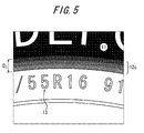
FIG. 5 is a partial enlarged side view of the tire inFIG. 2 from the decoration portion to the rim. - With reference to the drawings, the following describes an embodiment of the present invention.
- The following merely provides an example, and the structure and effects of each member are not limited to those described below.
- A
pneumatic tire 10 illustrated inFIG. 1 is provided with a tread portion 1 and aside portion 4, theside portion 4 includingsidewalls 2 continuous along the tire radial direction inner edge of the side of the tread portion 1 and extending inward in the tire radial direction, and beadportions 3 continuous along the tire radial direction inner edge of thesidewall 2. - The
tire 10 is provided with acarcass ply 6 extending between the pair ofbead portions 3. Thecarcass ply 6 extends toroidally from the tread portion 1 across the pair ofsidewalls 2 to the pair ofbead portions 3 and is fastened by turning up around abead core 5 embedded in eachbead portion 3. - As illustrated in
FIG. 2 ,marks 11 indicating a company name or the like and an annulardecoration printing portion 12 are formed by printing on the outer surface of theside portion 4, and an engraving 13 formed by a conventional raised/recessed surface, for example indicating tire size or the like, is applied between thedecoration printing portion 12 and the rim line position. - At least a portion of the
decoration printing portion 12 is provided on the outer surface of theside portion 4 further toward the tire radial direction outer side than a tiremaximum width position 4a. As in the embodiment illustrated inFIGS. 2 and3 , however, from the perspective of applying a sufficient decoration, thedecoration printing portion 12 is preferably provided on the outer surface of theside portion 4 starting near atread edge 1a, extending over the tiremaximum width position 4a, and ending at or near thebead portion 3. - From the perspective of decorativeness, the annular
decoration printing portion 12 is preferably perfectly annular, i.e. forming a continuous loop in the tire circumferential direction, yet the annulardecoration printing portion 12 may also be formed intermittently or at only a portion of the circumference. The same is true for the below-describedannular design portion 12a,annular gradation portions black portion 14, and the like. - Forming the
marks 11 anddecoration printing portion 12 by printing to be a desired value (brightness) improves visibility, and since the printed portion is a flat surface, air resistance during driving is lowered, thus improving fuel economy. Furthermore, cracks in the rubber surface of the side portion occur less easily, thereby improving durability. - On the other hand, by applying the engraving 13 formed by a raised/recessed surface to the inner circumferential area of the
decoration printing portion 12, unintended wear due to abrasion or the like can be effectively prevented. - Note that the area in which the
engraving 13 is applied has a small rotation radius and a small circumferential speed, and therefore the effect of the engraving on air resistance is relatively small. - As is clear from
FIG. 3 , thedecoration printing portion 12 is provided with adesign portion 12a and agradation portion 12b disposed on the tire radial direction outer side of thedesign portion 12a. - In the present embodiment, an annular design, in which the center of a satellite photograph of the earth is cut out, having a fixed width in the radial direction is formed in the
design portion 12a, as illustrated inFIG. 4 . Portions showing clouds are printed white, and portions showing the sea are printed blue. While not clearly shown in the figures, printing applied to thegradation portion 12b incrementally decreases in value from thedesign portion 12a towards the outer circumference in the tire radial direction, changing in color from white or blue to black. In thegradation portion 12b and the below-describedinner gradation portion 12c inFIGS. 1 to 3 and5 , portions with thick hatching have a high value, and portions with thin hatching have a low value. - In the
gradation portion 12b, the value may be changed in any way. For example, the value may be decreased linearly towards the outside in the tire radial direction. - Thus providing the
gradation portion 12b on theside portion 4 in the vicinity of thetread edge 1a relieves the sense of incongruity felt by a viewer when printing is applied near thetread edge 1a with a conventional technique, thereby increasing the decorativeness of the tire and reducing the noticeability of misprinting. - Furthermore, by decreasing the value in the
gradation portion 12b towards the outer circumference in the tire radial direction, the value of thedecoration printing portion 12 approaches the value of the tread portion 1, which for example has a value of 10%, with increasing proximity to thetread edge 1a. Therefore, no large difference in value occurs between thedecoration printing portion 12 and thetread edge 1a, thereby reducing the user's sense of incongruity. Moreover, by having the value in the largest area within theside portion 4, i.e. the vicinity of thetread edge 1a, approach the value of the tread portion itself results in a value even closer to the tire ground value. As a result, the amount of ink needed for printing can be reduced, and manufacturing costs can be greatly lowered. A thinner application of ink can also eliminate the risk of cracks in the printing layer. - When a satellite photograph of the earth is formed in the
design portion 12a, thegradation portion 12b looks like the stratosphere, thus reducing the sense of incongruity when a user views the tire side portion. - Also when a satellite photograph of the earth is not formed on the
design portion 12a, similar effects can of course be achieved by selecting subject matter for thedesign portion 12a that yields no sense of incongruity despite thedesign portion 12a turning black toward the edge, and other designs may also be printed in thedesign portion 12a. - Furthermore, as illustrated in
FIG. 3 , when a width DG of thegradation portion 12b in the tire radial direction is at least 3 mm, and preferably at least 5 mm, and the value of thegradation portion 12b decreases linearly outward in the tire radial direction, then thedecoration printing portion 12 appears more natural since the value changes gradually due to thegradation portion 12b. Furthermore, the width of thedesign portion 12a in the tire radial direction can be guaranteed, thereby further reducing the sense of incongruity felt by the viewer and further increasing the decorativeness. By guaranteeing a certain width for thegradation portion 12b, the noticeability of unevenness or runny ink occurring during printing can be reduced even more at the outer edge of thedecoration printing portion 12. When the width DG of thegradation portion 12b in the tire radial direction is too large, the width of thedesign portion 12a in the tire radial direction narrows, thus decreasing the decorativeness. Therefore, a limit of 10 mm is preferably placed on the width DG of thegradation portion 12b in the tire radial direction. - A raised/recessed special shape is often provided on the
side portion 4 in the vicinity of thetread edge 1a. Also, when printing on theside portion 4 in the vicinity of thetread edge 1a, decorativeness may be reduced due to abrasion or defacement from rubbing against a curb or the like. - Therefore, an annular
black portion 14, having a width DB in the tire radial direction of at least 3 mm and at most 5 mm, is preferably provided in thedecoration printing portion 12 between thetread edge 1a and thegradation portion 12b, adjacent to the tire radial direction inner side of thetread edge 1a. The value of theblack portion 14 is preferably 20% or less, for example 10%. In this case, substantially no decoration is provided on theside portion 4 in the vicinity of thetread edge 1a, with substantial decoration being provided further towards a tire radial direction inner side than the vicinity of the side ring. Therefore, even if a raised/recessed special shape is formed on theside portion 4 in the vicinity of the tread, misprinting or the like can be sufficiently hidden by theblack portion 14, the effect of abrasion or defacement from a curb or the like can be reduced, and decorativeness can be guaranteed by guaranteeing sufficient width of thedecoration printing portion 12 in the tire radial direction. - As an example of forming the
side portion 4 in the vicinity of the tread to be a special shape, the vicinity of the side ring may be provided with curvature in order to prevent the occurrence of an air reservoir between the tread ring and the side ring in the mold during the vulcanization process. - When the width of the
black portion 14 in the tire radial direction is too great, the width of thedecoration printing portion 12 in the tire radial direction narrows, thus reducing the decorativeness. Therefore, the width of theblack portion 14 in the tire radial direction is preferably 5 mm or less. - In other words, if the width DB of the
black portion 14 in the tire radial direction is less than 3 mm, then when forming a raised/recessed special shape on theside portion 4 in the vicinity of thetread edge 1a, misprinting cannot be sufficiently hidden, and the tire is more easily affected by abrasion or defacement due to a curb or the like. - Furthermore, if the width DB of the
black portion 14 in the tire radial direction is greater than 5 mm, the width of thedecoration printing portion 12 in the tire radial direction decreases, thus preventing the achievement of sufficient decorativeness. - When no printing is applied to the
black portion 14, theblack portion 14 may be left the same color as the tire ground color. In this case, the amount of ink required for printing can be reduced, thereby further lowering manufacturing costs. A thinner application of ink can also more effectively prevent the occurrence of cracks in the printing layer. - On the other hand, the
black portion 14 may be formed by applying printing to theblack portion 14 so that the value of theblack portion 14 is equivalent to the value of thetread edge 1a or the value at the edge of thedesign portion 12b on the tire radial direction outer side. - By thus providing the
black portion 14, the value of thedecoration printing portion 12 in the vicinity of thetread edge 1a can be brought even closer to the tire ground value, and the amount of ink required for printing can be reduced, thereby further lowering manufacturing costs. A thinner application of ink can also more effectively prevent the occurrence of cracks in the printing layer. - When the expression Dp ≥ D holds, where Dp is the width of the
decoration printing portion 12 in the tire radial direction, and D is the width in the tire radial direction between thetread edge 1a and the tiremaximum width position 4a, as illustrated inFIG. 3 , then the decoration printing portion is formed over a circular uneven portion. This uneven portion occurs in the tire side portion, due to the existence of the turn-up end of a carcass ply, within a range from the tread edge to the tire maximum width position. Therefore, this uneven portion is made less noticeable, enhancing the decorativeness and reducing the sense of incongruity that a viewer feels due to the uneven section when viewing the side portion. The tire user's uneasiness is thus dispelled and the tire is made more attractive, with an improved quality of appearance. - When the difference in value between edges of the
gradation portion 12b in the tire radial direction is in a range of at least 30% and less than 50%, the color of the design portion is highlighted while relieving the sense of incongruity that the viewer feels and enhancing the decorativeness with the decoration printing portion. - On the other hand, when the difference in value of the
gradation portion 12b is 50% or more, then by forming a design with a high value in thedesign portion 12a and increasing the difference in value between the tread portion 1 and thedesign portion 12a, thedesign portion 12a can be made to appear even brighter. Furthermore, the decoration appears more natural by incrementally decreasing the value from an area at the tire radial direction outer side of thedesign portion 12a with a high value towards the low valueblack portion 14 or thetread edge 1a, located further on the tire radial direction outer side, thus further enhancing the decorativeness. Misaligned or blurry printing on theside portion 4 in the vicinity of thetread edge 1a also becomes less noticeable, so that decorativeness is even further enhanced. - When the value of at least the outer edge of the
gradation portion 12b in the tire radial direction is 20% or less, the value of the printed decoration further approaches the value of thetread edge 1a itself with increasing proximity to thetread edge 1a. Therefore, the sense of incongruity felt by the user or the like can be further reduced and the decorativeness further enhanced. Furthermore, since the value of at least the outer edge in the tire radial direction is brought even closer to the tire ground value, the amount of ink required for printing can be even further reduced, further lowering manufacturing costs. The application of ink can also be made thinner, thereby preventing the occurrence of cracks in the printing layer. The noticeability of unevenness or runny ink occurring during printing can also be reduced even more at the outer edge of the gradation portion, and misprinting can be made even less noticeable. - In the illustrated embodiment, an
additional gradation portion 12c may be provided on the tire radial direction inner side of thedesign portion 12a. As illustrated inFIG. 5 , in thisgradation portion 12c, the width DI of thegradation portion 12c in the tire radial direction is at least 3 mm, preferably at least 5 mm, and while not clear fromFIG. 5 , the value incrementally decreases towards the inner circumference in the tire radial direction. In this case, thegradation portion 12c appears to be set back from thedesign portion 12a, making it appear as though a wide tire were mounted. Therefore, a user desiring a wide tire is satisfied, and when forming decoration by printing, the sense of incongruity felt by a viewer with regard to the vicinity of the rim 21 is relieved. Decorativeness can thus be enhanced, and the occurrence of misprinting can be even further reduced. - If the width DI of the
gradation portion 12c in the tire radial direction is too large, the width of thedesign portion 12a or thegradation portion 12c in the tire radial direction narrows, decreasing the decorativeness. Hence, the width DI of thegradation portion 12c in the tire radial direction is preferably 10 mm or less. - Note that the difference in value between edges of the
gradation portion 12c in the tire radial direction may be 30% or more, and the value of at least the inner edge in the tire radial direction may be 20% or less. In these cases, decorativeness can be further enhanced. - Furthermore, when an interval Ds measuring, in the tire radial direction, at least 15 mm and at most 50% of the width Dp of the
decoration printing portion 12 in the tire radial direction is provided between thedecoration printing portion 12 and the rim line position, as illustrated inFIG. 2 , then the width of the design portion in the tire radial direction can be guaranteed, so as to guarantee decorativeness, while removing decoration from the vicinity of the rim line, where theengraving 13 of a serial number or the like required by law is provided. The visibility of the serial number or the like can thus be increased. - In other words, if the interval Ds is more than 50% of the width Dp, the roughly black tire ground color at the tire radial direction inner side of the
side portion 4 becomes noticeable, and the width of the design portion 11 a in the tire radial direction is reduced, so that decorativeness cannot be sufficiently enhanced. - Note that in the above-described embodiment, the structure of the present invention is adopted on both tire sides, yet the structure of the present invention may be adopted on only one half side of the tire, in particular the outer side when vehicle mounted.
- As described below, the sense of incongruity felt by a viewer was investigated for Example Tires 1 to 26 according to the present invention and a Comparative Tire that were produced to have design portions formed thereon. Specifically, 50 viewers observed the produced tires and answered a questionnaire regarding whether they felt a sense of incongruity. For each tire, the number of viewers not feeling a sense of incongruity was totaled. Table 1 shows the results. Using the investigation results for the Comparative Tire as a control, the investigation results for each tire are indicated as an index. A greater value (decorativeness) for the sense of incongruity indicates less of a sense of incongruity for the tire and better decorativeness.
- For the Example Tires 1 to 26, the size was 195/65R15, and on the tire side portion, which had a width of 75 mm in the tire radial direction, an interval of 15 mm in the tire radial direction was provided from the rim line position, and an inner gradation portion, design portion, gradation portion, and black portion, respectively having widths of DI, DD, DG, and DB in the tire radial direction, were provided adjacently in this order towards the tire radial direction outer side. The width D in the tire radial direction between the tread edge and the tire maximum width position was 35 mm.
- A decoration in which the center of a satellite photograph of the earth is cut out was formed in the decoration printing portion, as illustrated in
FIG. 4 . The value of the tire ground color at the side portion and the tread portion and the value of the black portion were 10%, and the value of the gradation portion and the inner gradation portion (when present) was changed linearly in the tire radial direction so that the difference in value between edges the tire radial direction was ΔV (%). - On the other hand, in the Comparative Tire, the gradation portion, inner gradation portion, and black portion were not provided in the side portion. Instead, a design portion, bearing a decoration in which the center of a satellite photograph of the earth is cut out, was formed over the entire surface except for an area with a width of 15 mm in the tire radial direction from the rim line position. Otherwise, the Comparative Tire was similar to the Example Tires 1 to 26.


- The results indicate that the user felt a lesser sense of incongruity with respect to the Example Tires, in which the gradation portion was provided in the side portion, than the Comparative Tire. Hence, the Example Tires had enhanced decorativeness. In particular, when DG was 5 mm or more, the sense of incongruity was clearly reduced greatly. Providing the black portion and the inner gradation portion also clearly reduced the sense of incongruity even further.
- Furthermore, setting the difference in value of the gradation portion in the radial direction to be 50% or more clearly achieved a greater reduction in the sense of incongruity.
- As described below, 50 each of Example Tires 1 and 20 according to the present invention and the Comparative Tire were produced, and the number of tires for which misprinting was discovered due to unevenness or runny ink was investigated. Table 2 shows the results. The Example Tires 1 and 20 and Comparative Tire produced here were the same as the Example Tires 1 and 20 and Comparative Tire of Example 1. In other words, in Example Tire 1, the gradation portion was formed only on the outer side of the decoration portion in the tire radial direction, and in Example Tire 20, the gradation portion was formed on the outer and inner sides in the tire radial direction. In the Comparative Tire, no gradation portion was formed.
[Table 2] Example Tire 1 Example Tire 20 Comparative Tire Outer side gradation YES YES NO Inner side gradation NO YES NO Number of misprints 1 0 3 - The results indicate that for Example Tires 1 and 20 provided with the gradation portion on the tire radial direction outer side, the number of tires with misprinting was reduced with respect to the Comparative Tire. Also, providing the gradation portion on the tire radial direction inner side as well clearly further reduced the number of tires with misprinting.
-
- 1: Tread portion
- 1a: Tread edge (tire radial direction inner edge of a tread side portion)
- 2: Sidewall
- 3: Bead portion
- 4: Side portion
- 4a: Tire maximum width position
- 5: Bead core
- 6: Carcass ply
- 10: Tire
- 11: Mark
- 12: Decoration printing portion
- 12a: Design portion
- 12b: Gradation portion
- 12c: Inner gradation portion
- 13: Engraving
- 14: Black portion
- D: Width in tire radial direction between tread edge and tire maximum width position
- DB: Width of black portion gradation portion in tire radial direction
- DD: Width of design portion in tire radial direction
- DG: Width of gradation portion in tire radial direction
- DI: Width of inner gradation portion in tire radial direction
- DP: Width of decoration printing portion in tire radial direction
- DS: Engraving portion in vicinity of rim line
Claims (9)
- A pneumatic tire comprising:a side portion including a sidewall and a bead portion, the sidewall being continuous along a tire radial direction inner edge of a tread side portion and extending inward in the tire radial direction, and the bead portion being continuous along a tire radial direction inner edge of the sidewall; andan annular decoration printing portion, at least a portion thereof being provided on an outer surface of the side portion further toward a tire radial direction outer side than a tire maximum width position,the decoration printing portion including an annular design portion and an annular gradation portion provided at least on the tire radial direction outer side of the design portion, andthe gradation portion incrementally decreasing in value outward in the tire radial direction, with a value of 100% being a pure color and a value of 0% being pure black in an HSV color space.
- The pneumatic tire according to claim 1, a width of the gradation portion in the tire radial direction being at least 3 mm and at most 10 mm, and the gradation portion incrementally decreasing in value outward in the tire radial direction.
- The pneumatic tire according to claim 1 or 2, further comprising:an annular black portion, having a width in the tire radial direction of at least 3 mm and at most 5 mm, on the outer surface of the side portion, positioned between the tread side portion and the gradation portion, adjacent to a tire radial direction inner side of the tire radial direction inner edge of the tread side portion,a value of the black portion being 20% or less.
- The pneumatic tire according to any one of claims 1 through 3, satisfying the expression Dp ≥ D, where Dp is a width of the decoration printing portion in the tire radial direction, and D is a width in the tire radial direction between the tire radial direction inner edge of the tread side portion and the tire maximum width position.
- The pneumatic tire according to any one of claims 1 through 4, a difference in value between edges of the gradation portion in the tire radial direction being at least 30% and less than 50%.
- The pneumatic tire according to any one of claims 1 through 4, a difference in value between edges of the gradation portion in the tire radial direction being 50% or more.
- The pneumatic tire according to any one of claims 1 through 6, a value of at least an outer edge of the gradation portion in the tire radial direction being 20% or less.
- The pneumatic tire according to any one of claims 1 through 7,
the decoration printing portion including an additional gradation portion on a tire radial direction inner side of the design portion, and
a width of the additional gradation portion in the tire radial direction being at least 3 mm and at most 10 mm, and the additional gradation portion incrementally decreasing in value inward in the tire radial direction. - The pneumatic tire according to any one of claims 1 through 8, an interval measuring, in the tire radial direction, at least 15 mm and at most 50% of the width Dp being provided between the decoration printing portion and a rim line position.
Applications Claiming Priority (2)
| Application Number | Priority Date | Filing Date | Title |
|---|---|---|---|
| JP2011232088A JP5769583B2 (en) | 2011-10-21 | 2011-10-21 | Pneumatic tire |
| PCT/JP2012/077813 WO2013058412A1 (en) | 2011-10-21 | 2012-10-22 | Pneumatic tire |
Publications (3)
| Publication Number | Publication Date |
|---|---|
| EP2769857A1 true EP2769857A1 (en) | 2014-08-27 |
| EP2769857A4 EP2769857A4 (en) | 2015-07-29 |
| EP2769857B1 EP2769857B1 (en) | 2019-05-15 |
Family
ID=48141051
Family Applications (1)
| Application Number | Title | Priority Date | Filing Date |
|---|---|---|---|
| EP12842471.0A Not-in-force EP2769857B1 (en) | 2011-10-21 | 2012-10-22 | Pneumatic tire |
Country Status (5)
| Country | Link |
|---|---|
| US (1) | US9555670B2 (en) |
| EP (1) | EP2769857B1 (en) |
| JP (1) | JP5769583B2 (en) |
| CN (1) | CN103857541B (en) |
| WO (1) | WO2013058412A1 (en) |
Cited By (1)
| Publication number | Priority date | Publication date | Assignee | Title |
|---|---|---|---|---|
| EP2781375A4 (en) * | 2011-11-08 | 2015-07-29 | Bridgestone Corp | Tire |
Families Citing this family (5)
| Publication number | Priority date | Publication date | Assignee | Title |
|---|---|---|---|---|
| WO2013069802A1 (en) * | 2011-11-08 | 2013-05-16 | 株式会社ブリヂストン | Pneumatic tire |
| WO2013125592A1 (en) * | 2012-02-21 | 2013-08-29 | 横浜ゴム株式会社 | Pneumatic tire and production method for pneumatic tire |
| JP2014223935A (en) * | 2013-05-17 | 2014-12-04 | アサヒビール株式会社 | Metal can |
| US10443339B2 (en) | 2016-06-23 | 2019-10-15 | Schlumberger Technology Corporation | Elastomeric materials |
| KR101840289B1 (en) * | 2017-08-28 | 2018-03-20 | 오행준 | Identifiable bicycle wheels |
Family Cites Families (15)
| Publication number | Priority date | Publication date | Assignee | Title |
|---|---|---|---|---|
| JPS5643881B2 (en) | 1973-07-27 | 1981-10-15 | ||
| JPS5438006A (en) * | 1977-08-30 | 1979-03-22 | Mitsuboshi Belting Ltd | Color tire and its preparation |
| JP2000255223A (en) * | 1999-03-05 | 2000-09-19 | Bridgestone Corp | Tire |
| JP2002120519A (en) * | 2000-10-13 | 2002-04-23 | Masayuki Kuzuu | Color tire |
| JP2002192624A (en) * | 2000-12-27 | 2002-07-10 | Bridgestone Corp | Tire manufacturing method |
| CN2546230Y (en) | 2002-05-27 | 2003-04-23 | 华丰橡胶工业股份有限公司 | tire bead decoration |
| FR2852889A1 (en) * | 2003-03-28 | 2004-10-01 | Michelin Soc Tech | TIRE COMPRISING A COLORED PATTERN AND PROCESS FOR OBTAINING IT |
| KR20050037821A (en) | 2003-10-20 | 2005-04-25 | 한국타이어 주식회사 | Tire stuck copy film |
| US20050224153A1 (en) | 2004-04-12 | 2005-10-13 | Al Speyer | Use of colored indicia on tires as a designator |
| JP2006224704A (en) * | 2005-02-15 | 2006-08-31 | Bridgestone Corp | Pneumatic tire |
| RU2462369C1 (en) * | 2008-06-17 | 2012-09-27 | Дзе Йокогама Раббер Ко., Лтд. | Pneumatic tire |
| JP5346565B2 (en) | 2008-12-01 | 2013-11-20 | 株式会社ブリヂストン | Inkjet printing device for donut type (ring type) articles |
| JP5322610B2 (en) * | 2008-12-08 | 2013-10-23 | 東洋ゴム工業株式会社 | Pneumatic tire and method for manufacturing pneumatic tire |
| JP2010195236A (en) * | 2009-02-25 | 2010-09-09 | Bridgestone Corp | Tire |
| DE102010016069B4 (en) | 2010-03-22 | 2024-10-10 | Continental Reifen Deutschland Gmbh | Method for producing a reflective or fluorescent layer on a sidewall of a pneumatic vehicle tire |
-
2011
- 2011-10-21 JP JP2011232088A patent/JP5769583B2/en not_active Expired - Fee Related
-
2012
- 2012-10-22 CN CN201280049818.1A patent/CN103857541B/en not_active Expired - Fee Related
- 2012-10-22 WO PCT/JP2012/077813 patent/WO2013058412A1/en not_active Ceased
- 2012-10-22 US US14/351,658 patent/US9555670B2/en not_active Expired - Fee Related
- 2012-10-22 EP EP12842471.0A patent/EP2769857B1/en not_active Not-in-force
Cited By (1)
| Publication number | Priority date | Publication date | Assignee | Title |
|---|---|---|---|---|
| EP2781375A4 (en) * | 2011-11-08 | 2015-07-29 | Bridgestone Corp | Tire |
Also Published As
| Publication number | Publication date |
|---|---|
| WO2013058412A1 (en) | 2013-04-25 |
| US9555670B2 (en) | 2017-01-31 |
| CN103857541A (en) | 2014-06-11 |
| US20140332135A1 (en) | 2014-11-13 |
| CN103857541B (en) | 2016-08-17 |
| JP2013086769A (en) | 2013-05-13 |
| EP2769857B1 (en) | 2019-05-15 |
| EP2769857A4 (en) | 2015-07-29 |
| JP5769583B2 (en) | 2015-08-26 |
Similar Documents
| Publication | Publication Date | Title |
|---|---|---|
| EP2614968B1 (en) | Tire | |
| EP2769857B1 (en) | Pneumatic tire | |
| EP2792506B1 (en) | Tire | |
| CN103917385B (en) | tire | |
| EP2623341B1 (en) | Tyre | |
| EP2818335A1 (en) | Pneumatic tire | |
| JP5902380B2 (en) | tire | |
| CN105189147B (en) | The printing process of tire and surface of tyre | |
| EP2805836B1 (en) | Decorated rubber and tire | |
| EP2777954B1 (en) | Pneumatic tire | |
| JP2014133450A (en) | Pneumatic tire | |
| JP5566362B2 (en) | tire | |
| CN119682444A (en) | Pneumatic tires |
Legal Events
| Date | Code | Title | Description |
|---|---|---|---|
| PUAI | Public reference made under article 153(3) epc to a published international application that has entered the european phase |
Free format text: ORIGINAL CODE: 0009012 |
|
| 17P | Request for examination filed |
Effective date: 20140414 |
|
| AK | Designated contracting states |
Kind code of ref document: A1 Designated state(s): AL AT BE BG CH CY CZ DE DK EE ES FI FR GB GR HR HU IE IS IT LI LT LU LV MC MK MT NL NO PL PT RO RS SE SI SK SM TR |
|
| DAX | Request for extension of the european patent (deleted) | ||
| RA4 | Supplementary search report drawn up and despatched (corrected) |
Effective date: 20150630 |
|
| RIC1 | Information provided on ipc code assigned before grant |
Ipc: B60C 13/00 20060101AFI20150624BHEP |
|
| GRAP | Despatch of communication of intention to grant a patent |
Free format text: ORIGINAL CODE: EPIDOSNIGR1 |
|
| STAA | Information on the status of an ep patent application or granted ep patent |
Free format text: STATUS: GRANT OF PATENT IS INTENDED |
|
| INTG | Intention to grant announced |
Effective date: 20181126 |
|
| GRAS | Grant fee paid |
Free format text: ORIGINAL CODE: EPIDOSNIGR3 |
|
| GRAA | (expected) grant |
Free format text: ORIGINAL CODE: 0009210 |
|
| STAA | Information on the status of an ep patent application or granted ep patent |
Free format text: STATUS: THE PATENT HAS BEEN GRANTED |
|
| AK | Designated contracting states |
Kind code of ref document: B1 Designated state(s): AL AT BE BG CH CY CZ DE DK EE ES FI FR GB GR HR HU IE IS IT LI LT LU LV MC MK MT NL NO PL PT RO RS SE SI SK SM TR |
|
| REG | Reference to a national code |
Ref country code: CH Ref legal event code: EP Ref country code: GB Ref legal event code: FG4D |
|
| REG | Reference to a national code |
Ref country code: DE Ref legal event code: R096 Ref document number: 602012060217 Country of ref document: DE |
|
| REG | Reference to a national code |
Ref country code: IE Ref legal event code: FG4D |
|
| REG | Reference to a national code |
Ref country code: NL Ref legal event code: MP Effective date: 20190515 |
|
| REG | Reference to a national code |
Ref country code: LT Ref legal event code: MG4D |
|
| PG25 | Lapsed in a contracting state [announced via postgrant information from national office to epo] |
Ref country code: NO Free format text: LAPSE BECAUSE OF FAILURE TO SUBMIT A TRANSLATION OF THE DESCRIPTION OR TO PAY THE FEE WITHIN THE PRESCRIBED TIME-LIMIT Effective date: 20190815 Ref country code: AL Free format text: LAPSE BECAUSE OF FAILURE TO SUBMIT A TRANSLATION OF THE DESCRIPTION OR TO PAY THE FEE WITHIN THE PRESCRIBED TIME-LIMIT Effective date: 20190515 Ref country code: FI Free format text: LAPSE BECAUSE OF FAILURE TO SUBMIT A TRANSLATION OF THE DESCRIPTION OR TO PAY THE FEE WITHIN THE PRESCRIBED TIME-LIMIT Effective date: 20190515 Ref country code: SE Free format text: LAPSE BECAUSE OF FAILURE TO SUBMIT A TRANSLATION OF THE DESCRIPTION OR TO PAY THE FEE WITHIN THE PRESCRIBED TIME-LIMIT Effective date: 20190515 Ref country code: HR Free format text: LAPSE BECAUSE OF FAILURE TO SUBMIT A TRANSLATION OF THE DESCRIPTION OR TO PAY THE FEE WITHIN THE PRESCRIBED TIME-LIMIT Effective date: 20190515 Ref country code: NL Free format text: LAPSE BECAUSE OF FAILURE TO SUBMIT A TRANSLATION OF THE DESCRIPTION OR TO PAY THE FEE WITHIN THE PRESCRIBED TIME-LIMIT Effective date: 20190515 Ref country code: PT Free format text: LAPSE BECAUSE OF FAILURE TO SUBMIT A TRANSLATION OF THE DESCRIPTION OR TO PAY THE FEE WITHIN THE PRESCRIBED TIME-LIMIT Effective date: 20190915 Ref country code: LT Free format text: LAPSE BECAUSE OF FAILURE TO SUBMIT A TRANSLATION OF THE DESCRIPTION OR TO PAY THE FEE WITHIN THE PRESCRIBED TIME-LIMIT Effective date: 20190515 Ref country code: ES Free format text: LAPSE BECAUSE OF FAILURE TO SUBMIT A TRANSLATION OF THE DESCRIPTION OR TO PAY THE FEE WITHIN THE PRESCRIBED TIME-LIMIT Effective date: 20190515 |
|
| PG25 | Lapsed in a contracting state [announced via postgrant information from national office to epo] |
Ref country code: GR Free format text: LAPSE BECAUSE OF FAILURE TO SUBMIT A TRANSLATION OF THE DESCRIPTION OR TO PAY THE FEE WITHIN THE PRESCRIBED TIME-LIMIT Effective date: 20190816 Ref country code: BG Free format text: LAPSE BECAUSE OF FAILURE TO SUBMIT A TRANSLATION OF THE DESCRIPTION OR TO PAY THE FEE WITHIN THE PRESCRIBED TIME-LIMIT Effective date: 20190815 Ref country code: RS Free format text: LAPSE BECAUSE OF FAILURE TO SUBMIT A TRANSLATION OF THE DESCRIPTION OR TO PAY THE FEE WITHIN THE PRESCRIBED TIME-LIMIT Effective date: 20190515 Ref country code: LV Free format text: LAPSE BECAUSE OF FAILURE TO SUBMIT A TRANSLATION OF THE DESCRIPTION OR TO PAY THE FEE WITHIN THE PRESCRIBED TIME-LIMIT Effective date: 20190515 |
|
| REG | Reference to a national code |
Ref country code: AT Ref legal event code: MK05 Ref document number: 1132980 Country of ref document: AT Kind code of ref document: T Effective date: 20190515 |
|
| PG25 | Lapsed in a contracting state [announced via postgrant information from national office to epo] |
Ref country code: CZ Free format text: LAPSE BECAUSE OF FAILURE TO SUBMIT A TRANSLATION OF THE DESCRIPTION OR TO PAY THE FEE WITHIN THE PRESCRIBED TIME-LIMIT Effective date: 20190515 Ref country code: RO Free format text: LAPSE BECAUSE OF FAILURE TO SUBMIT A TRANSLATION OF THE DESCRIPTION OR TO PAY THE FEE WITHIN THE PRESCRIBED TIME-LIMIT Effective date: 20190515 Ref country code: EE Free format text: LAPSE BECAUSE OF FAILURE TO SUBMIT A TRANSLATION OF THE DESCRIPTION OR TO PAY THE FEE WITHIN THE PRESCRIBED TIME-LIMIT Effective date: 20190515 Ref country code: AT Free format text: LAPSE BECAUSE OF FAILURE TO SUBMIT A TRANSLATION OF THE DESCRIPTION OR TO PAY THE FEE WITHIN THE PRESCRIBED TIME-LIMIT Effective date: 20190515 Ref country code: DK Free format text: LAPSE BECAUSE OF FAILURE TO SUBMIT A TRANSLATION OF THE DESCRIPTION OR TO PAY THE FEE WITHIN THE PRESCRIBED TIME-LIMIT Effective date: 20190515 Ref country code: SK Free format text: LAPSE BECAUSE OF FAILURE TO SUBMIT A TRANSLATION OF THE DESCRIPTION OR TO PAY THE FEE WITHIN THE PRESCRIBED TIME-LIMIT Effective date: 20190515 |
|
| REG | Reference to a national code |
Ref country code: DE Ref legal event code: R097 Ref document number: 602012060217 Country of ref document: DE |
|
| PG25 | Lapsed in a contracting state [announced via postgrant information from national office to epo] |
Ref country code: IT Free format text: LAPSE BECAUSE OF FAILURE TO SUBMIT A TRANSLATION OF THE DESCRIPTION OR TO PAY THE FEE WITHIN THE PRESCRIBED TIME-LIMIT Effective date: 20190515 Ref country code: SM Free format text: LAPSE BECAUSE OF FAILURE TO SUBMIT A TRANSLATION OF THE DESCRIPTION OR TO PAY THE FEE WITHIN THE PRESCRIBED TIME-LIMIT Effective date: 20190515 |
|
| PLBE | No opposition filed within time limit |
Free format text: ORIGINAL CODE: 0009261 |
|
| STAA | Information on the status of an ep patent application or granted ep patent |
Free format text: STATUS: NO OPPOSITION FILED WITHIN TIME LIMIT |
|
| PG25 | Lapsed in a contracting state [announced via postgrant information from national office to epo] |
Ref country code: TR Free format text: LAPSE BECAUSE OF FAILURE TO SUBMIT A TRANSLATION OF THE DESCRIPTION OR TO PAY THE FEE WITHIN THE PRESCRIBED TIME-LIMIT Effective date: 20190515 |
|
| 26N | No opposition filed |
Effective date: 20200218 |
|
| PG25 | Lapsed in a contracting state [announced via postgrant information from national office to epo] |
Ref country code: PL Free format text: LAPSE BECAUSE OF FAILURE TO SUBMIT A TRANSLATION OF THE DESCRIPTION OR TO PAY THE FEE WITHIN THE PRESCRIBED TIME-LIMIT Effective date: 20190515 |
|
| PG25 | Lapsed in a contracting state [announced via postgrant information from national office to epo] |
Ref country code: SI Free format text: LAPSE BECAUSE OF FAILURE TO SUBMIT A TRANSLATION OF THE DESCRIPTION OR TO PAY THE FEE WITHIN THE PRESCRIBED TIME-LIMIT Effective date: 20190515 Ref country code: MC Free format text: LAPSE BECAUSE OF FAILURE TO SUBMIT A TRANSLATION OF THE DESCRIPTION OR TO PAY THE FEE WITHIN THE PRESCRIBED TIME-LIMIT Effective date: 20190515 |
|
| REG | Reference to a national code |
Ref country code: CH Ref legal event code: PL |
|
| PG25 | Lapsed in a contracting state [announced via postgrant information from national office to epo] |
Ref country code: LI Free format text: LAPSE BECAUSE OF NON-PAYMENT OF DUE FEES Effective date: 20191031 Ref country code: CH Free format text: LAPSE BECAUSE OF NON-PAYMENT OF DUE FEES Effective date: 20191031 Ref country code: LU Free format text: LAPSE BECAUSE OF NON-PAYMENT OF DUE FEES Effective date: 20191022 |
|
| REG | Reference to a national code |
Ref country code: BE Ref legal event code: MM Effective date: 20191031 |
|
| PG25 | Lapsed in a contracting state [announced via postgrant information from national office to epo] |
Ref country code: BE Free format text: LAPSE BECAUSE OF NON-PAYMENT OF DUE FEES Effective date: 20191031 |
|
| GBPC | Gb: european patent ceased through non-payment of renewal fee |
Effective date: 20191022 |
|
| PG25 | Lapsed in a contracting state [announced via postgrant information from national office to epo] |
Ref country code: GB Free format text: LAPSE BECAUSE OF NON-PAYMENT OF DUE FEES Effective date: 20191022 Ref country code: IE Free format text: LAPSE BECAUSE OF NON-PAYMENT OF DUE FEES Effective date: 20191022 |
|
| PG25 | Lapsed in a contracting state [announced via postgrant information from national office to epo] |
Ref country code: CY Free format text: LAPSE BECAUSE OF FAILURE TO SUBMIT A TRANSLATION OF THE DESCRIPTION OR TO PAY THE FEE WITHIN THE PRESCRIBED TIME-LIMIT Effective date: 20190515 |
|
| PG25 | Lapsed in a contracting state [announced via postgrant information from national office to epo] |
Ref country code: IS Free format text: LAPSE BECAUSE OF FAILURE TO SUBMIT A TRANSLATION OF THE DESCRIPTION OR TO PAY THE FEE WITHIN THE PRESCRIBED TIME-LIMIT Effective date: 20190915 |
|
| PG25 | Lapsed in a contracting state [announced via postgrant information from national office to epo] |
Ref country code: HU Free format text: LAPSE BECAUSE OF FAILURE TO SUBMIT A TRANSLATION OF THE DESCRIPTION OR TO PAY THE FEE WITHIN THE PRESCRIBED TIME-LIMIT; INVALID AB INITIO Effective date: 20121022 Ref country code: MT Free format text: LAPSE BECAUSE OF FAILURE TO SUBMIT A TRANSLATION OF THE DESCRIPTION OR TO PAY THE FEE WITHIN THE PRESCRIBED TIME-LIMIT Effective date: 20190515 |
|
| PG25 | Lapsed in a contracting state [announced via postgrant information from national office to epo] |
Ref country code: MK Free format text: LAPSE BECAUSE OF FAILURE TO SUBMIT A TRANSLATION OF THE DESCRIPTION OR TO PAY THE FEE WITHIN THE PRESCRIBED TIME-LIMIT Effective date: 20190515 |
|
| PGFP | Annual fee paid to national office [announced via postgrant information from national office to epo] |
Ref country code: FR Payment date: 20221031 Year of fee payment: 11 |
|
| PGFP | Annual fee paid to national office [announced via postgrant information from national office to epo] |
Ref country code: DE Payment date: 20221019 Year of fee payment: 11 |
|
| P01 | Opt-out of the competence of the unified patent court (upc) registered |
Effective date: 20230531 |
|
| REG | Reference to a national code |
Ref country code: DE Ref legal event code: R119 Ref document number: 602012060217 Country of ref document: DE |
|
| PG25 | Lapsed in a contracting state [announced via postgrant information from national office to epo] |
Ref country code: FR Free format text: LAPSE BECAUSE OF NON-PAYMENT OF DUE FEES Effective date: 20231031 Ref country code: DE Free format text: LAPSE BECAUSE OF NON-PAYMENT OF DUE FEES Effective date: 20240501 |